


Languages
Pages
Legal

MICRO POWER SYSTEM 10
MODULAR -48 VDC, 17 AMP
Front Access Switchmode Rectifier System Product Manual Part Number: 4380467PD Issue 1, December 2008
43
804
67
PD

PECO II, Inc. MPS 10 Manual
Issue 1, December 2008 Page 3
- This page intentionally left blank -
Table of Contents
SECTION 1: GENERAL .........................................................................................................................................10
1.1 GENERAL.....................................................................................................................................................10 1.2 FEATURES...................................................................................................................................................10
SECTION 2: PRODUCT DESCRIPTION.............................................................................................................12
2.1 MICRO POWER SYSTEM OVERVIEW .......................................................................................................12 2.2 BASIC SYSTEM SHELF WITH CONTROLLER...........................................................................................12 2.3 DISTRIBUTION MODULE ..........................................................................................................................14
2.3.1 L20 DISTRIBUTION MODULE ..........................................................................................................14 2.4.1 MSC1100 CONTROLLER FEATURES...............................................................................................15
2.5 SYSTEM SPECIFICATIONS ........................................................................................................................16 2.5.1 SHELF LIFE..........................................................................................................................................16 2.5.2 DATE CODE INTERPRETATION......................................................................................................17 2.6 MSM06A50 RECTIFIER MODULE .......................................................................................................17 2.6.1 MSM06A50 RECTIFIER MODULE INPUT SPECIFICATIONS.......................................................18 2.6.2 MSM06A50 RECTIFIER MODULE OUTPUT SPECIFICATIONS...................................................18
SECTION 3: INSTALLATION ..............................................................................................................................20
3.1 GENERAL.....................................................................................................................................................20 3.2 INSTALLATION TOOLS ..............................................................................................................................20 3.3 PARTS LIST..................................................................................................................................................20 3.4 MPS10 PRE-INSTALLATION CHECK ........................................................................................................21 3.5 INSTALLER MECHANICAL AND POWER ELECTRICAL NOTES............................................................21 3.6 MECHANICAL INSTALLATION OF THE MPS10 ......................................................................................21 3.7 MECHANICAL INSTALLATION OF THE ACU CONTROLLER ................................................................23 3.8 OFFICE ALARM CONNECTIONS ..............................................................................................................24 3.9 COMMERCIAL AC INPUT CONNECTIONS TO THE SHELF...................................................................26 3.10 C.O. GROUND INSTALLATION................................................................................................................27
3.10.1 CHASSIS GROUND............................................................................................................................27 3.11 RECTIFIER MODULE INSTALLATION ...................................................................................................28 3.12 RECTIFIER MODULE REMOVAL............................................................................................................28 3.13 L20 DISTRIBUTION MODULE BATTERY CONNECTIONS....................................................................29
3.13.1 -48VDC BATTERY RETURN ...........................................................................................................29 3.13.2 -48VDC BATTERY SUPPLY ............................................................................................................30
3.14 GMT LOAD CONNECTIONS ....................................................................................................................30 3.14.1 GMT LOAD RETURN CONNECTIONS ..........................................................................................30 3.14.2 GMT LOAD CONNECTIONS ...........................................................................................................30
3.15 GMT FUSE INSTALLATION......................................................................................................................32 3.16 OPTIONAL (L60) BATTERY TEMPERATURE PROBE INSTALLATION ................................................32
SECTION 4: INITIAL START-UP ........................................................................................................................33
4.1 TEST AND TURN UP...................................................................................................................................33
SECTION 5: MPS10 ACU CONTROLLER..........................................................................................................35
5.1 ACU DESCRIPTION....................................................................................................................................35 5.2 FRONT PANEL ............................................................................................................................................35
SECTION 6: REMOTE MONITORING SOFTWARE (ARMS) NAVIGATION..............................................37
6.1 GENERAL.....................................................................................................................................................37 6.2 BATTERY......................................................................................................................................................39
6.2.1 SUMMARY...........................................................................................................................................39 6.2.2 PARAMETERS.....................................................................................................................................40
6.2.2.1 PARAMETERS FACTORY DEFAULT SETTINGS....................................................................40 6.2.3 BATTERY TEST ..................................................................................................................................41
6.2.3.1 MANUAL MODE ..........................................................................................................................41 6.2.3.2 PERIODIC MODE .........................................................................................................................41
PECO II, Inc. MPS 10 Manual
Issue 1, December 2008 Page 5
6.2.3.3 BATTERY TEST CRITERIA ........................................................................................................41 6.2.3.4 BATTERY TEST FAILED CONDITION .....................................................................................41 6.2.3.4 BATTERY TEST PASSED CONDITION.....................................................................................42
6.2.4 BATTERY TEMPERATURE COMPENSATION...............................................................................43 6.2.5 BOOST CHARGE.................................................................................................................................44
6.2.5.1 VOLTAGE MODE.........................................................................................................................45 6.2.5.2 CAPACITY MODE........................................................................................................................45 6.2.5.3 RECHARGE MODE ......................................................................................................................46 6.2.5.4 PERIODIC MODE .........................................................................................................................46 6.2.5.5 BOOST / MANUAL CHARGE – STOP CRITERIA ....................................................................46
6.3 ALARM PARAMETER SETTINGS ...............................................................................................................47 6.3.1 DC ALARMS ........................................................................................................................................47 6.3.2 BATTERY TEMPERATURE ALARM................................................................................................48 6.3.3 MAJOR ALARMS ................................................................................................................................49 6.3.4 MINOR ALARMS ................................................................................................................................51 6.3.5 RELAY DEFINITIONS ........................................................................................................................53
6.4 CONFIGURATION.......................................................................................................................................56 6.4.1 LVDS FUNCTION................................................................................................................................56
6.4.1.1 VOLTAGE MODE.........................................................................................................................57 6.4.1.1.1 LVD1 CONTROL .........................................................................................................................57 6.4.1.1.2 LVD2 CONTROL .........................................................................................................................57 6.4.1.1.3 LVD3 CONTROL .........................................................................................................................57 6.4.1.2 TEMPERATURE MODE...............................................................................................................57 6.4.1.2.1 LVD CONTROL ...........................................................................................................................57
SECTION 7: SNMP SETUP.....................................................................................................................................59
7.1 GENERAL.....................................................................................................................................................59 7.2 FACTORY DEFAULT NETWORK SETTINGS ............................................................................................59
7.2.1 GENERAL NETWORK SETTINGS ..............................................................................................59 7.3 SNMP TRAP DETAILS.................................................................................................................................60 7.4 USER INTERFACE - CUSTOMIZE SETTINGS VIA TELNET SESSION ....................................................60 7.5 LED FUNCTIONALITY................................................................................................................................63
SECTION 8: RECTIFIER SPECIFICATIONS ....................................................................................................65
8.1 MSM06A50, -48V / 6 AMP RECTIFIER INPUT SPECIFICATIONS ..........................................................65 8.2 OUTPUT SPECIFICATIONS .......................................................................................................................65 8.4 PHYSICAL SPECIFICATIONS ....................................................................................................................65 8.5 ENVIRONMENTAL CHARACTERISTICS ...................................................................................................66 8.6 ELECTROMAGNETIC COMPATIBILITY EMISSION ................................................................................66 8.7 IMMUNITY...................................................................................................................................................66 8.8 RELIABILITY................................................................................................................................................66 8.9 PROTECTION ..............................................................................................................................................67 8.10 DISPLAY.....................................................................................................................................................67 8.11 ALARM .......................................................................................................................................................67 8.12 MISCELLANEOUS.....................................................................................................................................68
SECTION 9: REVISION HISTORY......................................................................................................................69
SECTION 10: J-DRAWING ...........................................................................................................................438173
SECTION 11: T-DRAWING...................................................................................................................... 4391725T
SECTION 12: SCHEMATIC DRAWING ..............................................................................................4391725SD

FFOORREEWWOORRDD This manual is intended to help the user of the MPS 10 install, test, troubleshoot, and understand the system. If you should have any questions or problems, please contact one of the following sources:
CONTACT INFORMATION:
REPAIRS AND EMERGENCY SERVICE: Field Service / After Market Services –
419/468-7700 or 1-888-317-1216
PARTS ORDERING - Replacement parts for power equipment may be obtained by forwarding a Purchase Order
to:
PECO II, Inc P. O. Box 910 Galion, Ohio 44833 or Fax to: (419) 462-8180 Include the following information:
A. PECO II part number and engineering level of equipment B. If part is electrical, give circuit reference numbers and PECO II part numbers. C. If part is mechanical in nature, give description as to where it is used.
RETURN & REPAIR – For PECOII Factory repaired and refurbished equipment
A. Call: 419/468-7700 Field Service Or 419-888-317-1216
B. Request a Returned Material Authorization (RMA) number for the defective equipment. C. Return material prepaid to:
PECO II, Inc 1376 State Route 598 Galion, Ohio 44833 Attn: Field Service Dept

PECO II, Inc. MPS 10 Manual
Issue 1, December 2008 Page 7
WWAARRNNIINNGGSS CCAAUUTTIIOONNSS
1. Follow proper grounding instructions. Suivre fonder correctes les instructions.
1. Electrical shock hazard. Do not attempt to remove, maintain, or install this equipment with power applied. Personnel that attempt to work on this equipment with the power applied may subject themselves or others to electrical shock that may cause serious injury or death. Le danger électrique de choc. Pas la tentative pour enlever, maintenir, ou installer cet équipement avec le pouvoir appliqué. Le personnel qui tente traiter cet équipement avec le pouvoir appliqué peut s'exposer ou les autres au choc électrique qui peut causer la blessure ou la mort sérieuse
2. If connecting batteries, remove the battery-box-fuse or trip the circuit breaker. Check batteries and connections for proper polarity and power before connecting the batteries to the system. Si connectant des piles, enlever la pile-boîte-le fusible ou trébuche le disjoncteur. Vérifier des piles et des connexions pour la polarité et le pouvoir correcte avant de connecter les piles au système.
2. The use of this equipment by unauthorized or
untrained personnel should not be attempted. Personnel that work on this equipment without the proper training may subject themselves or others to electrical shock that may cause serious injury or death. L'usage de cet équipement par le personnel inautorisé ou sans formation ne devrait pas être tenté. Le personnel qui traite cet équipement sans l'entraînement correct peut s'exposer ou les autres au choc électrique qui peut causer la blessure ou la mort sérieuse
3. To remove the circuit breakers or fuses, the DC and/or AC input to the system will need to be disconnected, thereby disabling the system output to the load(s). Take the necessary precautions and inform the plant engineer that the system output power to the loads will be disabled. Pour enlever les disjoncteurs ou les fusibles, les données de courant alternatif de et/ou de DC au système auront besoin d'être débranché, de cette façon rendant infirme la production de système au chargement (les chargements). Prendre les précautions nécessaires et informer l'ingénieur de plante que le pouvoir de production de système aux chargements seront rendus infirme. .
4. Before performing any maintenance, ensure AC
or DC power is not applied to the system. Avant d'exécuter n'importe quel entretien, assurer que le pouvoir de courant alternatif ou DC n'est pas appliqué au système.
3. Do not attempt to work on this equipment if it is, or has been, exposed to a high moisture condition. It is recommended the equipment be returned to PECO II to be properly tested. Working on this equipment during a high moisture condition subjects the user to electrical shock that may cause serious injury or death. Pas la tentative pour traiter cet équipement si c'est, ou a été, exposé à une haute condition d'humidité. Il est recommandé l'équipement s'est retourné à PECO deux être convenablement essayé. Traiter cet équipement pendant une haute condition d'humidité expose l'utilisateur au choc électrique qui peut causer la blessure ou la mort sérieuse.
5. Fuse holders, fuses, and circuit breakers are not to be loaded to more than 80 percent of their ampere rating. Fondez les supports, fusibles, et des disjoncteurs ne doivent pas être chargés à plus de 80 pour cent de leur estimation d'ampère.

4. Use of an attachment other than one approved by PECO II will void any and all warranties, implied or other, and will increase risk of fire, or may possibly cause electrical shock, injury, or death to personnel. L'usage d'un attachement autrement qu'un approuvé par PECO II annulera n'importe quel et toutes garanties, implicites ou autres, et augmentera le risque de feu, ou probablement peut causer le choc électrique, la blessure, ou la mort au personnel.
5. Do not operate this equipment if it has been
dropped or otherwise damaged. Trying to operate this equipment if it has been damaged subjects yourself or others to electrical shock that may cause serious injury or death. L'usage d'un attachement autrement qu'un approuvé par PECO II annulera n'importe quel et toutes garanties, implicites ou autres, et augmentera le risque de feu, ou probablement peut causer le choc électrique, la blessure, ou la mort au personnel.
6. Before you proceed, ensure the input source is not
live and the input circuit breaker(s)/fuse(s) has been tripped or removed. If these procedures have not been followed and the input/output power is live, serious personnel injury or death may occur. Avant que vous procédez, assurez que la source d'entrée n'est pas en vie et le circuit d'entrée breaker(s)/fuse(s) a été trébuché ou a été enlevé. Si ces procédures n'ont pas été suivies et le pouvoir input-output est la blessure de personnel ou la mort en vie et sérieux peut arriver
7. A rack/shelf may contain several operating systems.
If there is another system in the general area you want to install this system, be cautious of any exposed connectors or wires and, with permission, remove power to the other systems. Failure to take the necessary safety precautions subjects the installer or maintenance personnel to severe electrical shock that may cause serious injury or death. Une étagère/étagère peut contenir plusieurs systèmes d'exploitation. S'il y a un autre système dans le secteur général que vous voulez installer ce système, êtes prudent de connecteurs ou de fils exposés et, avec la permission, enlevez le pouvoir aux autres systèmes. L'échec pour prendre les précautions de sûreté nécessaires exposent le personnel d'installateur ou entretien au choc électrique sévère qui peut causer la blessure ou la mort sérieuse

PECO II, Inc. MPS 10 Manual
Issue 1, December 2008 Page 9
8. This equipment may connect to lead-acid batteries.
Battery posts, terminals, and related accessories contain lead and lead compounds, chemicals known to the state of California to cause cancer and birth defects or other reproductive harm. Wash hands
after touching batteries. Cet équipement peut connecter des piles mener-acides. Les postes de pile, les terminaux, et les accessoires apparentés contient l'avance et les premiers composés, les produits chimiques connus à l'état de Californie pour causer les défauts de cancer et naissance ou l'autre mal reproducteur. Laver des mains après avoir touché des piles.

SSEECCTTIIOONN 11:: GGEENNEERRAALL
1.1 GENERAL
The MPS10 is a micro power system optimized for use at the network edge. It works in both controlled and uncontrolled environments, enabling deployment in outside plant enclosures or at the customer premises. The low profile, compact, integrated design provides all of the power, distribution and management required for applications where space is at a premium. Designed for remote surveillance via standard alarm contacts or optional SNMP traps, the MPS10 can provide the necessary alarms and status conditions allowing the user to make informed decisions before conditions become critical.
FIGURE 1-1: BASIC SYSTEM LAYOUT
1.2 FEATURES
The standard features of the MPS 10 include:
• 1RU System Height, with 19” or 23” mountings
• Temperature hardened with output to + 75C
• 6 Amps per rectifier
• Input voltage choices from 90-310 VAC
• Front to rear cooling with variable speed fans for quiet operation
• Remote surveillance via six (6) hardwired alarm outputs or optional Ethernet SNMP trap interface
• Flush or mid-mount with rear access distribution terminations
• Single AC circuit powers the entire shelf
• Manual battery disconnect facilitates for maintenance, service or testing
• Optional low voltage disconnect (LVD)

PECO II, Inc. MPS 10 Manual
Issue 1, December 2008 Page 11
-This page intentionally left blank-
SSEECCTTIIOONN 22:: PPRROODDUUCCTT DDEESSCCRRIIPPTTIIOONN
2.1 MICRO POWER SYSTEM OVERVIEW
The Micro Power System (MPS) consists of a 1RU rectifier shelf, Alarm and Control Unit (ACU), a maximum of three rectifier modules, and a GMT type-A distribution. Alarm reporting is available through the standard 6 hardwired alarms outputs or optional SNMP trap. The MPS can also be equipped with an optional low voltage disconnect.
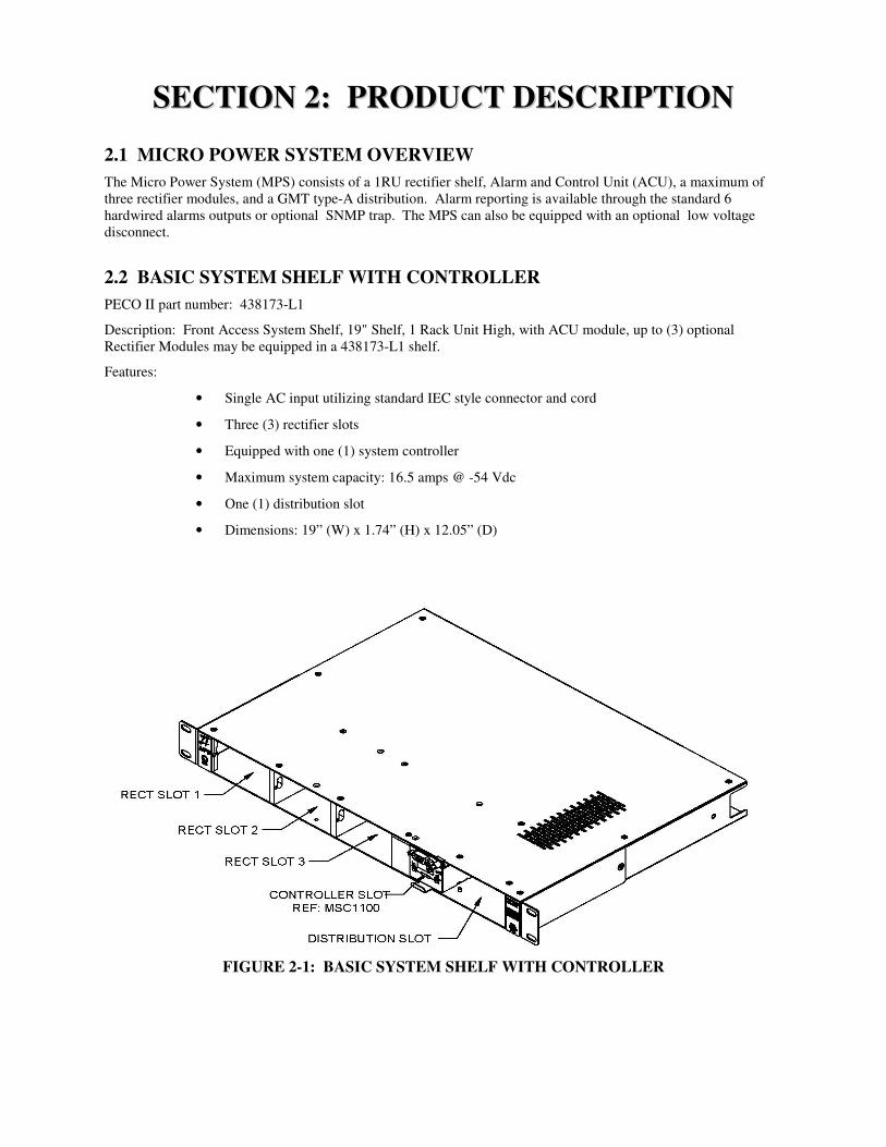
2.2 BASIC SYSTEM SHELF WITH CONTROLLER
PECO II part number: 438173-L1
Description: Front Access System Shelf, 19" Shelf, 1 Rack Unit High, with ACU module, up to (3) optional Rectifier Modules may be equipped in a 438173-L1 shelf.
Features:
• Single AC input utilizing standard IEC style connector and cord
• Three (3) rectifier slots
• Equipped with one (1) system controller
• Maximum system capacity: 16.5 amps @ -54 Vdc
• One (1) distribution slot
• Dimensions: 19” (W) x 1.74” (H) x 12.05” (D)
FIGURE 2-1: BASIC SYSTEM SHELF WITH CONTROLLER
PECO II, Inc. MPS 10 Manual
Issue 1, December 2008 Page 13
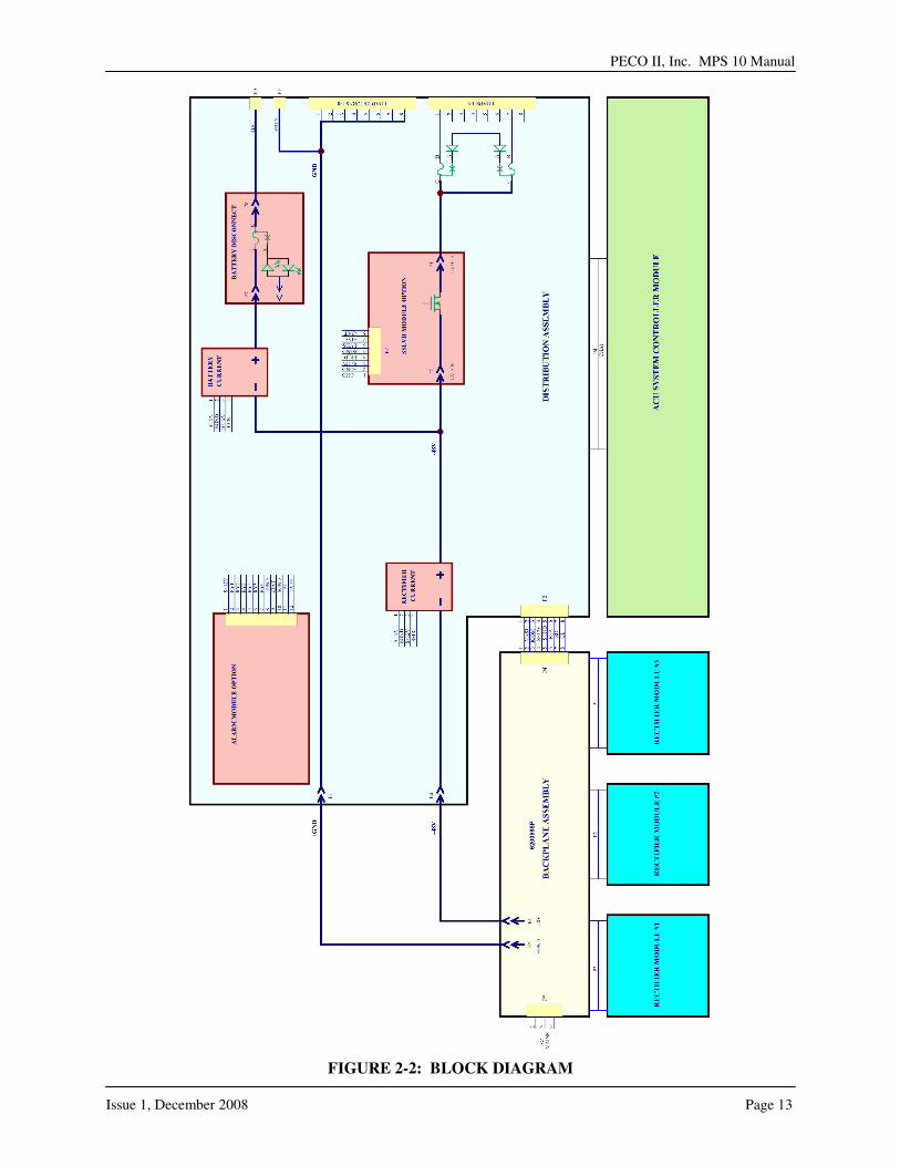
FIGURE 2-2: BLOCK DIAGRAM
2.3 DISTRIBUTION MODULE
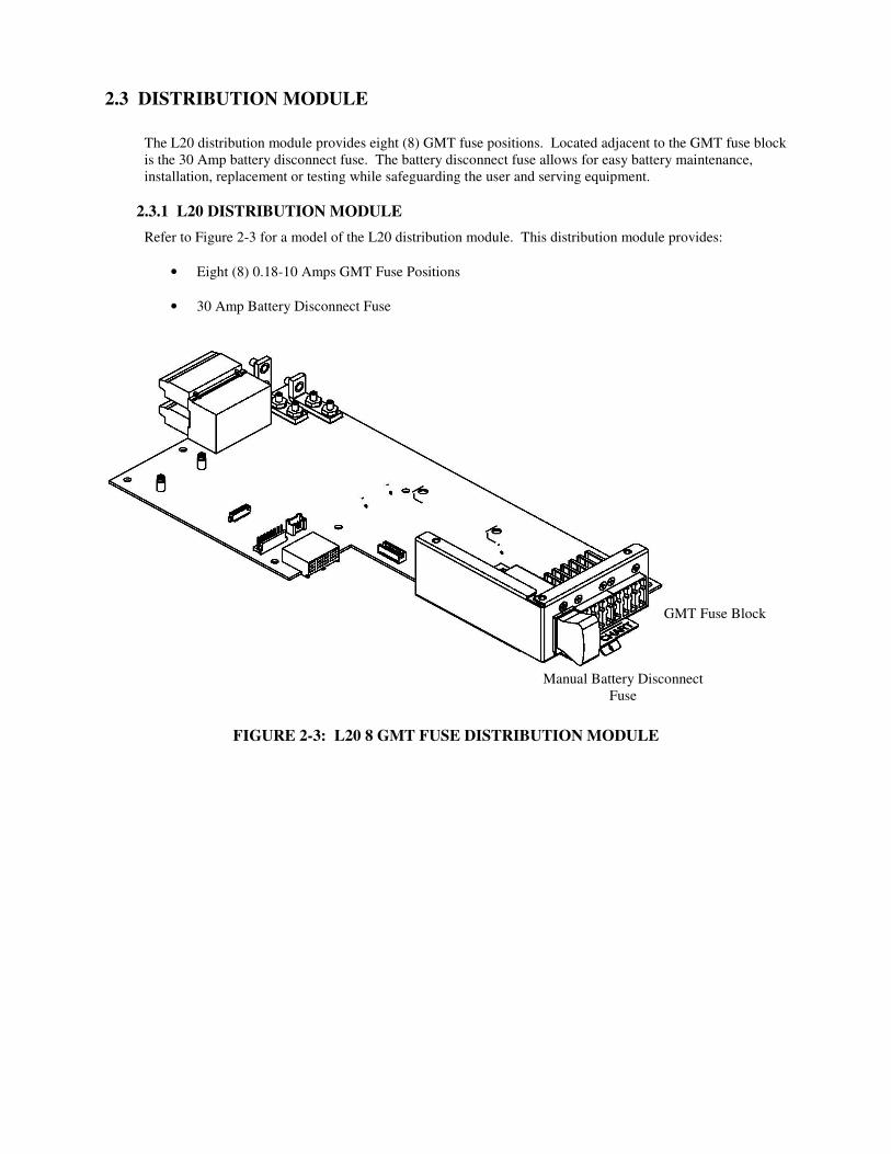
The L20 distribution module provides eight (8) GMT fuse positions. Located adjacent to the GMT fuse block is the 30 Amp battery disconnect fuse. The battery disconnect fuse allows for easy battery maintenance, installation, replacement or testing while safeguarding the user and serving equipment.
2.3.1 L20 DISTRIBUTION MODULE
Refer to Figure 2-3 for a model of the L20 distribution module. This distribution module provides:
• Eight (8) 0.18-10 Amps GMT Fuse Positions
• 30 Amp Battery Disconnect Fuse
FIGURE 2-3: L20 8 GMT FUSE DISTRIBUTION MODULE
GMT Fuse Block
Manual Battery Disconnect
Fuse
PECO II, Inc. MPS 10 Manual
Issue 1, December 2008 Page 15
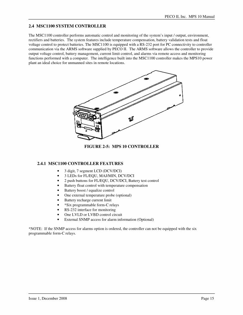
2.4 MSC1100 SYSTEM CONTROLLER The MSC1100 controller performs automatic control and monitoring of the system’s input / output, environment, rectifiers and batteries. The system features include temperature compensation, battery validation tests and float voltage control to protect batteries. The MSC1100 is equipped with a RS-232 port for PC connectivity to controller communication via the ARMS software supplied by PECO II. The ARMS software allows the controller to provide output voltage control, battery management, current limit control, and alarms via remote access and monitoring functions performed with a computer. The intelligence built into the MSC1100 controller makes the MPS10 power plant an ideal choice for unmanned sites in remote locations.
FIGURE 2-5: MPS 10 CONTROLLER
2.4.1 MSC1100 CONTROLLER FEATURES
• 3 digit, 7 segment LCD (DCV/DCI)
• 3 LEDs for FL/EQU, MAJ/MIN, DCV/DCI
• 2 push buttons for FL/EQU, DCV/DCI, Battery test control
• Battery float control with temperature compensation
• Battery boost / equalize control
• One external temperature probe (optional)
• Battery recharge current limit
• *Six programmable form-C relays
• RS-232 interface for monitoring
• One LVLD or LVBD control circuit
• External SNMP access for alarm information (Optional) *NOTE: If the SNMP access for alarms option is ordered, the controller can not be equipped with the six programmable form-C relays.
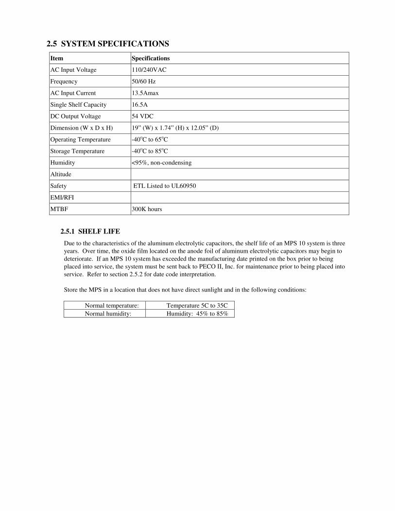
2.5 SYSTEM SPECIFICATIONS
Item Specifications
AC Input Voltage 110/240VAC
Frequency 50/60 Hz
AC Input Current 13.5Amax
Single Shelf Capacity 16.5A
DC Output Voltage 54 VDC
Dimension (W x D x H) 19” (W) x 1.74” (H) x 12.05” (D)
Operating Temperature -40oC to 65oC
Storage Temperature -40oC to 85oC
Humidity <95%, non-condensing
Altitude
Safety ETL Listed to UL60950
EMI/RFI
MTBF 300K hours
2.5.1 SHELF LIFE
Due to the characteristics of the aluminum electrolytic capacitors, the shelf life of an MPS 10 system is three
years. Over time, the oxide film located on the anode foil of aluminum electrolytic capacitors may begin to
deteriorate. If an MPS 10 system has exceeded the manufacturing date printed on the box prior to being
placed into service, the system must be sent back to PECO II, Inc. for maintenance prior to being placed into
service. Refer to section 2.5.2 for date code interpretation.
Store the MPS in a location that does not have direct sunlight and in the following conditions:
Normal temperature: Temperature 5C to 35C
Normal humidity: Humidity: 45% to 85%
PECO II, Inc. MPS 10 Manual
Issue 1, December 2008 Page 17
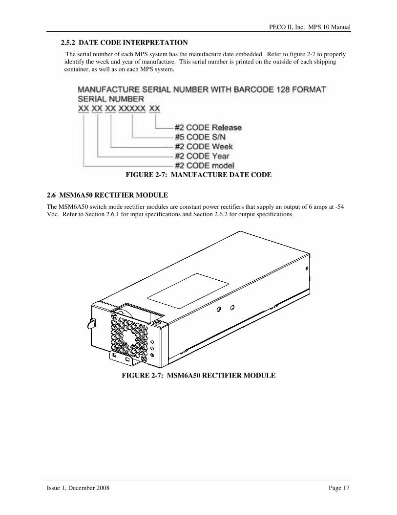
2.5.2 DATE CODE INTERPRETATION
The serial number of each MPS system has the manufacture date embedded. Refer to figure 2-7 to properly identify the week and year of manufacture. This serial number is printed on the outside of each shipping container, as well as on each MPS system.
FIGURE 2-7: MANUFACTURE DATE CODE
2.6 MSM6A50 RECTIFIER MODULE
The MSM6A50 switch mode rectifier modules are constant power rectifiers that supply an output of 6 amps at -54 Vdc. Refer to Section 2.6.1 for input specifications and Section 2.6.2 for output specifications.
FIGURE 2-7: MSM6A50 RECTIFIER MODULE

2.6.1 MSM6A50 RECTIFIER MODULE INPUT SPECIFICATIONS
Item Specification
Voltage range 90 to 310 Vac
Nominal 120/240 Vac
Input current, max <4.5 amps @ 90 Vac, 300W output
Inrush current, max <10.5 amps peak
2.6.2 MSM6A50 RECTIFIER MODULE OUTPUT SPECIFICATIONS
Item
Nominal output current 5.56 amps
Max. output current 5.56 amps @ 54 Vdc, 6.25 amps @ 48 Vdc
Current limit setpoint 7.1 ± 0.5 amps max., adjustable
Output power 300 W min. @ 90 to 276 Vac, 48 to 58 Vdc
Battery recharge capacity 300 W, full rated power @ 48 to 58 Vdc,
6.25 amps, 113% rated current @ 42 to 48 Vdc
Efficiency >87.5% @ full load,
>85% @ half load
Heat dissipation Maximum power dissipation < 35 W (120 BTU/hr)

PECO II, Inc. MPS 10 Manual
Issue 1, December 2008 Page 19
-This page intentionally left blank-

SSEECCTTIIOONN 33:: IINNSSTTAALLLLAATTIIOONN 3.1 GENERAL
Section 3 will guide the user through the installation of the MPS 10 system. Follow all directions closely and adhere to all cautions and warnings. Additional requirements may be required for specific installations.
CAUTION: The installation of the MPS10 exposes the user/installer to electrostatic
sensitive devices (ESD). For installation and repair, a personal ESD strap is required.
This equipment is designed to be installed into limited access locations only.
3.2 INSTALLATION TOOLS
Even though most initial installations are performed while the system is turned off, the use of properly insulated tools is recommended.
• Wire cutters and strippers
• SAE and Metric Socket Sets
• Digital meter, +/- 0.02%
• Screw Drivers (flat-blade and Phillips)
• Torque wrench (0-240 in-lb / 28 Nm)
• ESD wrist strap
3.3 PARTS LIST
The MPS10 system may be shipped to the customer in different stages of configurations based on order details, however, during the commissioning of the system the MPS10 must include parts and components as indicated below.
PECO II P/N Qty Description
MPS10 Shelf 438173-L1 1 19” basic shelf with ACU controller and (3) available rectifier slots and distribution slot.
Distribution Module
438173-L20 1 (8) 0-15A GMT fuses
Rectifier Module MSM6A50 Up to 3 Rectifier, -48Vdc 300W (6.25A) 220Vac input, 176-310VAC Front To Rear Air Flow
OR
Rectifier Slot Cover
4281003P As
required (up to 3)
All unoccupied rectifier positions must be covered with the Formex rectifier slot cover.
ACU (Controller) MSC1100 1 MPS10 ACU Controller, required with each system installation
PECO II, Inc. MPS 10 Manual
Issue 1, December 2008 Page 21
3.4 MPS10 PRE-INSTALLATION CHECK
A. Remove the system from the shipping carton and ensure all items are intact. If the contents are damaged, notify the delivery personnel and PECO II immediately.
B. Several options are available for the MPS10 and should have been determined when the order was
placed. Ensure the system configuration matches the order. C. Ensure required single-phase 120/240 VAC, 45-63 Hz is available at the selected plant location.
3.5 INSTALLER MECHANICAL AND POWER ELECTRICAL NOTES
Installer’s information notes: Torque requirements will comply with data outlined on unit labels except when otherwise specified by drawing or customer requirements. Floor anchors, AC wireways, and batteries should be chosen and torqued to meet customer / manufacturer recommendations.
Note 1: Equipment grounding conductor size (Frame or Chassis) is based on the recommendations of the National
Electric Code Table 250-95 for copper wire. #6 AWG is minimum size recommended. Note 2: Fuse or circuit breaker protection external to the system for commercial AC is to be provided by the
customer or contractor and should meet National Electrical Code standards. Note 3: DC wire sizes are based on the voltage drop considerations and the National Electric Code Table 310-16
for copper wire. Note 4: Installation of the system should be in an area that is accessible to qualified personnel only.
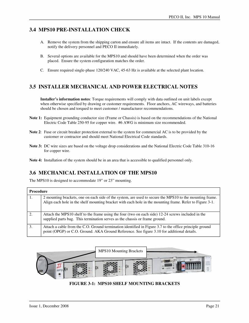
3.6 MECHANICAL INSTALLATION OF THE MPS10
The MPS10 is designed to accommodate 19” or 23” mounting.
Procedure
1. 2 mounting brackets, one on each side of the system, are used to secure the MPS10 to the mounting frame. Align each hole in the shelf mounting bracket with each hole in the mounting frame. Refer to Figure 3-1.
2. Attach the MPS10 shelf to the frame using the four (two on each side) 12-24 screws included in the supplied parts bag. This termination serves as the chassis or frame ground.
3. Attach a cable from the C.O. Ground termination identified in Figure 3.7 to the office principle ground point (OPGP) or C.O. Ground. AKA Ground Reference. See figure 3.10 for additional details.
FIGURE 3-1: MPS10 SHELF MOUNTING BRACKETS
MPS10 Mounting Brackets

PECO II, Inc. MPS 10 Manual
Issue 1, December 2008 Page 23
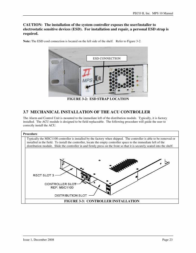
CAUTION: The installation of the system controller exposes the user/installer to
electrostatic sensitive devices (ESD). For installation and repair, a personal ESD strap is
required. Note: The ESD cord connection is located on the left side of the shelf. Refer to Figure 3-2.
FIGURE 3-2: ESD STRAP LOCATION
3.7 MECHANICAL INSTALLATION OF THE ACU CONTROLLER
The Alarm and Control Unit is mounted to the immediate left of the distribution module. Typically, it is factory installed. The ACU module is designed to be field replaceable. The following procedure will guide the user to correctly install the ACU.
Procedure
Typically the MSC1100 controller is installed by the factory when shipped. The controller is able to be removed or installed in the field. To install the controller, locate the empty controller space to the immediate left of the distribution module. Slide the controller in and firmly press on the front so that it is securely seated into the shelf.
FIGURE 3-3: CONTROLLER INSTALLATION
ESD CONNECTION

3.8 OFFICE ALARM CONNECTIONS
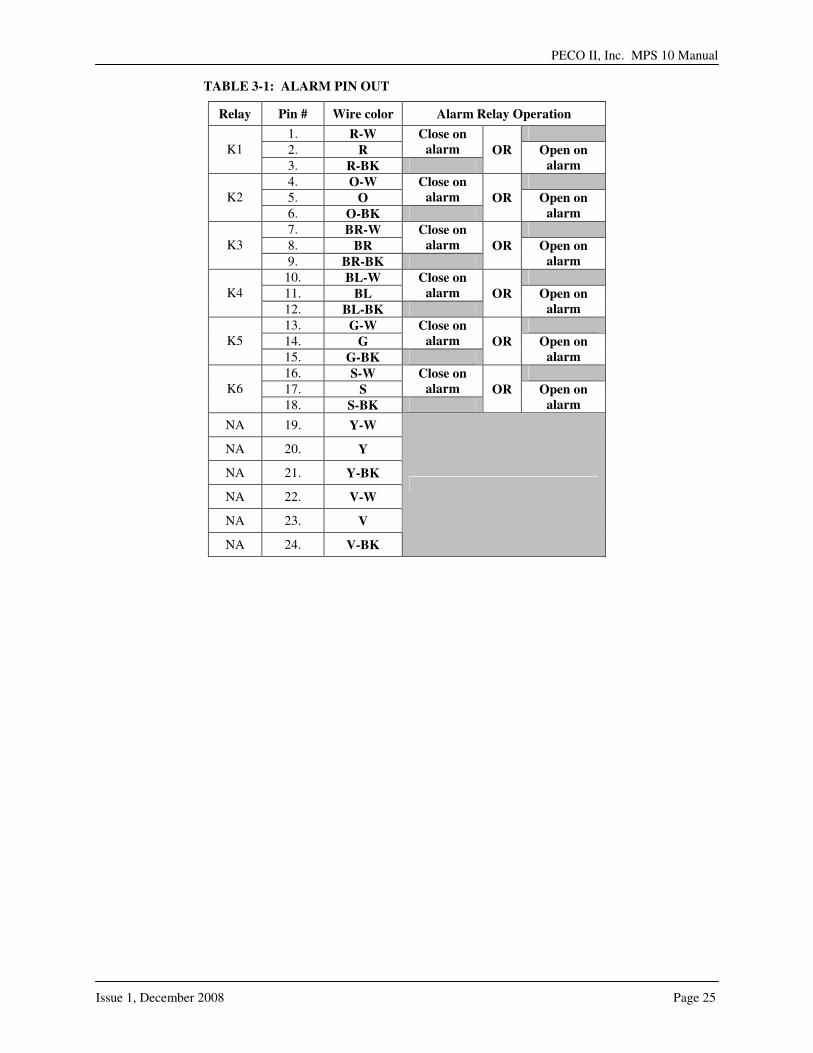
Located on the rear of the MPS10 to the immediate right of the load and load return connections is the location of the alarm connections. Two alarm output options are available. The L90 option provides an Ethernet port for SNMP alarm traps and a temperature probe connection (refer to figure 3-4) via an RJ45 type termination. The L91 provides six form-C relays (either CLOSE ON ALARM (NO) or OPEN ON ALARM (NC) and a temperature probe connection (refer to figure 3-5). The List 95 or 96 alarm cable is required with the List 91 relay alarm option. Refer to Table 3-1 for the alarm cable color code.
FIGURE 3-4: L90
FIGURE 3-5: L91
PECO II, Inc. MPS 10 Manual
Issue 1, December 2008 Page 25
TABLE 3-1: ALARM PIN OUT
Relay Pin # Wire color Alarm Relay Operation
1. R-W
2. R
Close on
alarm OR K1
3. R-BK
Open on
alarm
4. O-W
5. O
Close on
alarm OR K2
6. O-BK
Open on
alarm
7. BR-W
8. BR
Close on
alarm OR K3
9. BR-BK
Open on
alarm
10. BL-W
11. BL
Close on
alarm OR K4
12. BL-BK
Open on
alarm
13. G-W
14. G
Close on
alarm OR K5
15. G-BK
Open on
alarm
16. S-W
17. S
Close on
alarm OR K6
18. S-BK Open on
alarm
NA 19. Y-W
NA 20. Y
NA 21. Y-BK
NA 22. V-W
NA 23. V
NA 24. V-BK

3.9 COMMERCIAL AC INPUT CONNECTIONS TO THE SHELF
The MPS10 utilizes a standard IEC connector at the rear of the shelf to power the system (refer to figure 3-6A). Three choices of input power cord is available (refer to figure 3-6B).
FIGURE 3-6A: AC INPUT CONNECTIONS
L110 Power cord is 14 AWG. 9’10” long with an IEC connector to 5-15
L111 Power cord is 14 AWG. 9’10” long with an IEC connector to flying leads
L112 Power cord is 14 AWG. 9’10” long with an IEC connector to NEMA L620P
FIGURE 3-6B: AC INPUT POWER CORD OPTIONS
AC plug input location
PECO II, Inc. MPS 10 Manual
Issue 1, December 2008 Page 27
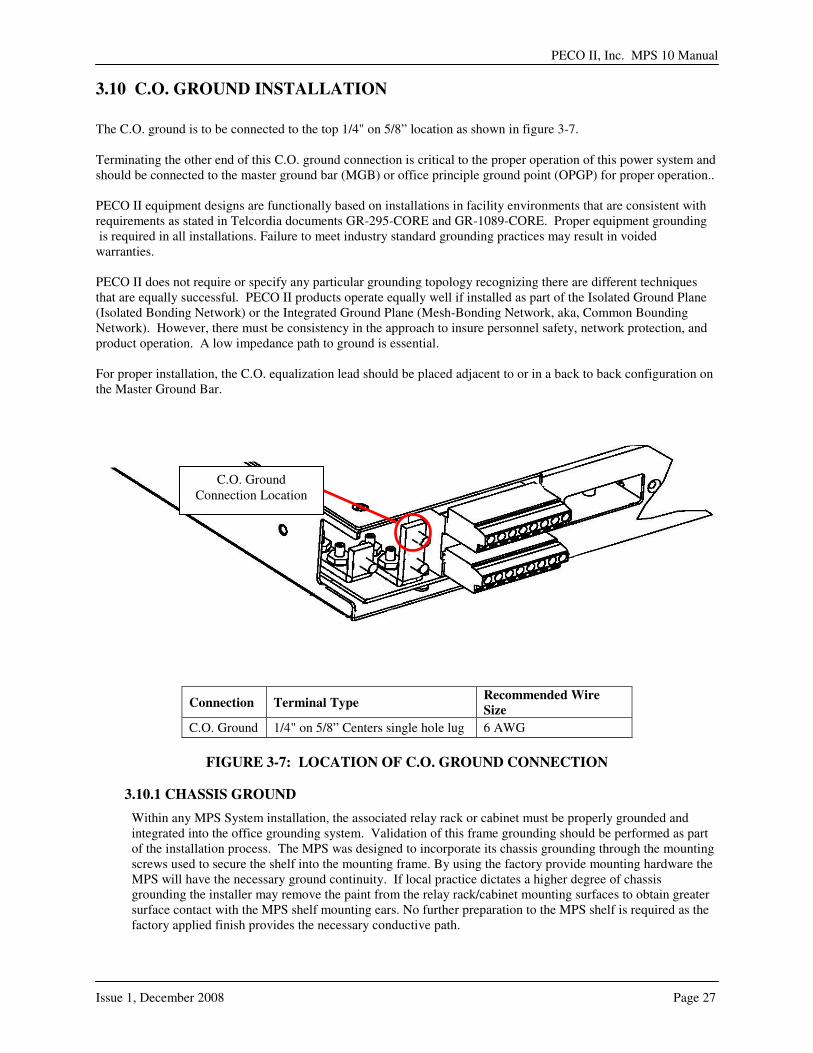
3.10 C.O. GROUND INSTALLATION
The C.O. ground is to be connected to the top 1/4" on 5/8” location as shown in figure 3-7. Terminating the other end of this C.O. ground connection is critical to the proper operation of this power system and should be connected to the master ground bar (MGB) or office principle ground point (OPGP) for proper operation.. PECO II equipment designs are functionally based on installations in facility environments that are consistent with requirements as stated in Telcordia documents GR-295-CORE and GR-1089-CORE. Proper equipment grounding is required in all installations. Failure to meet industry standard grounding practices may result in voided warranties.
PECO II does not require or specify any particular grounding topology recognizing there are different techniques that are equally successful. PECO II products operate equally well if installed as part of the Isolated Ground Plane (Isolated Bonding Network) or the Integrated Ground Plane (Mesh-Bonding Network, aka, Common Bounding Network). However, there must be consistency in the approach to insure personnel safety, network protection, and product operation. A low impedance path to ground is essential. For proper installation, the C.O. equalization lead should be placed adjacent to or in a back to back configuration on the Master Ground Bar.
Connection Terminal Type Recommended Wire
Size
C.O. Ground 1/4" on 5/8” Centers single hole lug 6 AWG
FIGURE 3-7: LOCATION OF C.O. GROUND CONNECTION
3.10.1 CHASSIS GROUND
Within any MPS System installation, the associated relay rack or cabinet must be properly grounded and integrated into the office grounding system. Validation of this frame grounding should be performed as part of the installation process. The MPS was designed to incorporate its chassis grounding through the mounting screws used to secure the shelf into the mounting frame. By using the factory provide mounting hardware the MPS will have the necessary ground continuity. If local practice dictates a higher degree of chassis grounding the installer may remove the paint from the relay rack/cabinet mounting surfaces to obtain greater surface contact with the MPS shelf mounting ears. No further preparation to the MPS shelf is required as the factory applied finish provides the necessary conductive path.
C.O. Ground Connection Location
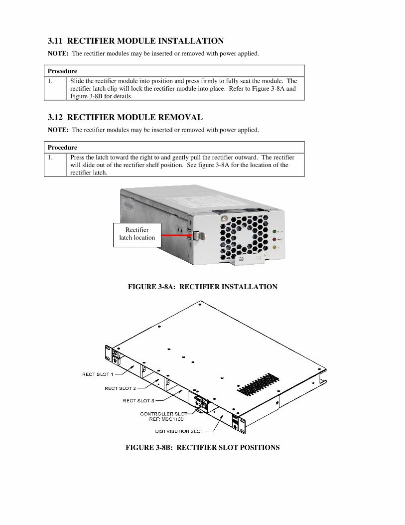
3.11 RECTIFIER MODULE INSTALLATION
NOTE: The rectifier modules may be inserted or removed with power applied.
Procedure
1. Slide the rectifier module into position and press firmly to fully seat the module. The rectifier latch clip will lock the rectifier module into place. Refer to Figure 3-8A and Figure 3-8B for details.
3.12 RECTIFIER MODULE REMOVAL
NOTE: The rectifier modules may be inserted or removed with power applied.
Procedure
1. Press the latch toward the right to and gently pull the rectifier outward. The rectifier will slide out of the rectifier shelf position. See figure 3-8A for the location of the rectifier latch.
FIGURE 3-8A: RECTIFIER INSTALLATION
FIGURE 3-8B: RECTIFIER SLOT POSITIONS
Rectifier latch location
PECO II, Inc. MPS 10 Manual
Issue 1, December 2008 Page 29
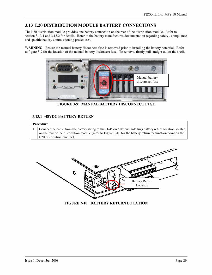
3.13 L20 DISTRIBUTION MODULE BATTERY CONNECTIONS
The L20 distribution module provides one battery connection on the rear of the distribution module. Refer to section 3.13.1 and 3.13.2 for details. Refer to the battery manufactures documentation regarding safety , compliance and specific battery commissioning procedures. WARNING: Ensure the manual battery disconnect fuse is removed prior to installing the battery potential. Refer to figure 3-9 for the location of the manual battery disconcert fuse. To remove, firmly pull straight out of the shelf.
FIGURE 3-9: MANUAL BATTERY DISCONNECT FUSE
3.13.1 -48VDC BATTERY RETURN
Procedure
1. Connect the cable from the battery string to the (1/4" on 5/8” one hole lug) battery return location located on the rear of the distribution module (refer to Figure 3-10 for the battery return termination point on the L20 distribution module).
FIGURE 3-10: BATTERY RETURN LOCATION
Battery Return Location
Manual battery disconnect fuse
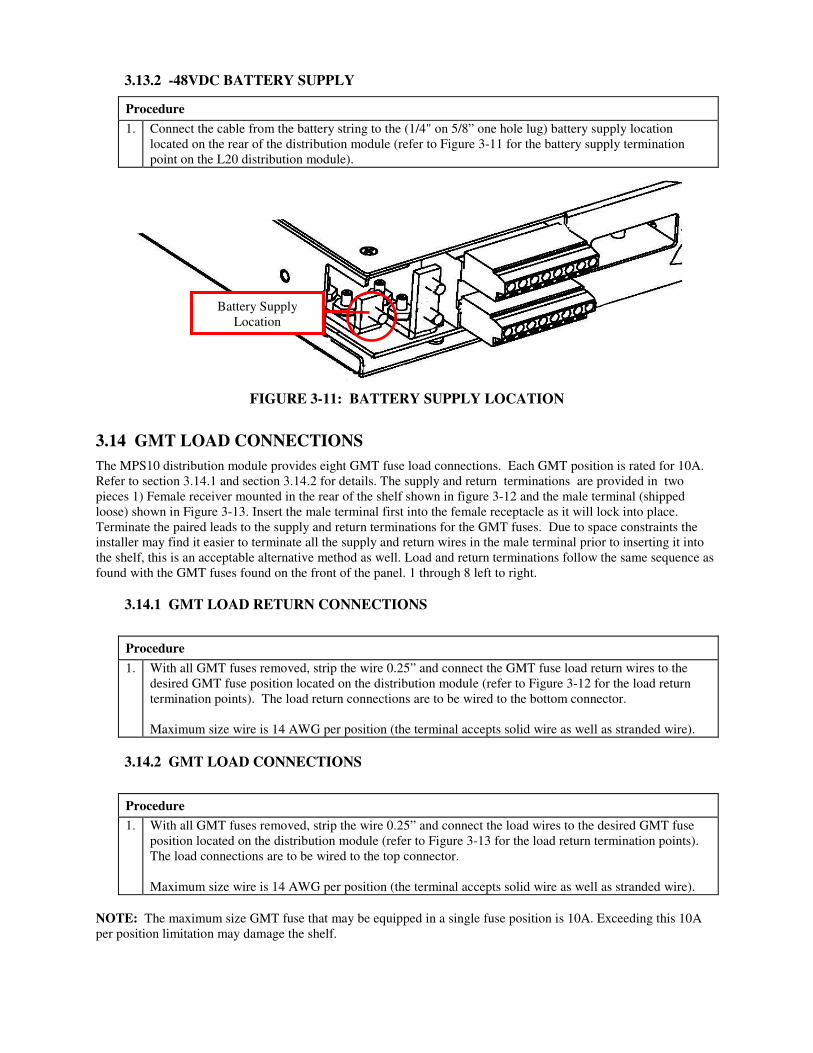
3.13.2 -48VDC BATTERY SUPPLY
Procedure
1. Connect the cable from the battery string to the (1/4" on 5/8” one hole lug) battery supply location located on the rear of the distribution module (refer to Figure 3-11 for the battery supply termination point on the L20 distribution module).
FIGURE 3-11: BATTERY SUPPLY LOCATION
3.14 GMT LOAD CONNECTIONS
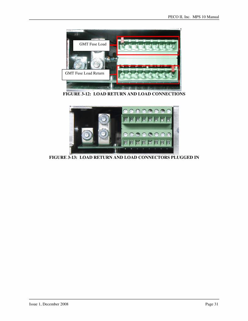
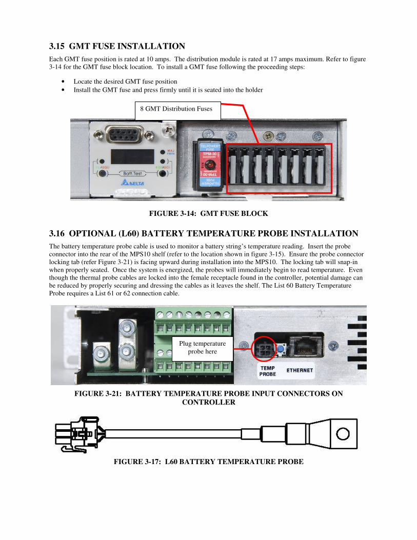
The MPS10 distribution module provides eight GMT fuse load connections. Each GMT position is rated for 10A. Refer to section 3.14.1 and section 3.14.2 for details. The supply and return terminations are provided in two pieces 1) Female receiver mounted in the rear of the shelf shown in figure 3-12 and the male terminal (shipped loose) shown in Figure 3-13. Insert the male terminal first into the female receptacle as it will lock into place. Terminate the paired leads to the supply and return terminations for the GMT fuses. Due to space constraints the installer may find it easier to terminate all the supply and return wires in the male terminal prior to inserting it into the shelf, this is an acceptable alternative method as well. Load and return terminations follow the same sequence as found with the GMT fuses found on the front of the panel. 1 through 8 left to right.
3.14.1 GMT LOAD RETURN CONNECTIONS
Procedure
1. With all GMT fuses removed, strip the wire 0.25” and connect the GMT fuse load return wires to the desired GMT fuse position located on the distribution module (refer to Figure 3-12 for the load return termination points). The load return connections are to be wired to the bottom connector. Maximum size wire is 14 AWG per position (the terminal accepts solid wire as well as stranded wire).
3.14.2 GMT LOAD CONNECTIONS
Procedure
1. With all GMT fuses removed, strip the wire 0.25” and connect the load wires to the desired GMT fuse position located on the distribution module (refer to Figure 3-13 for the load return termination points). The load connections are to be wired to the top connector. Maximum size wire is 14 AWG per position (the terminal accepts solid wire as well as stranded wire).
NOTE: The maximum size GMT fuse that may be equipped in a single fuse position is 10A. Exceeding this 10A per position limitation may damage the shelf.
Battery Supply Location
PECO II, Inc. MPS 10 Manual
Issue 1, December 2008 Page 31
FIGURE 3-12: LOAD RETURN AND LOAD CONNECTIONS
FIGURE 3-13: LOAD RETURN AND LOAD CONNECTORS PLUGGED IN
GMT Fuse Load Return
GMT Fuse Load
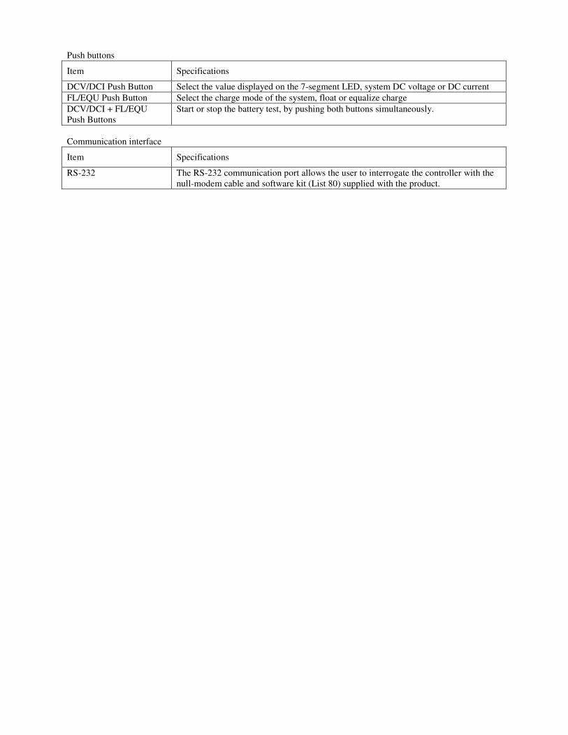
3.15 GMT FUSE INSTALLATION
Each GMT fuse position is rated at 10 amps. The distribution module is rated at 17 amps maximum. Refer to figure 3-14 for the GMT fuse block location. To install a GMT fuse following the proceeding steps:
• Locate the desired GMT fuse position
• Install the GMT fuse and press firmly until it is seated into the holder
FIGURE 3-14: GMT FUSE BLOCK
3.16 OPTIONAL (L60) BATTERY TEMPERATURE PROBE INSTALLATION
The battery temperature probe cable is used to monitor a battery string’s temperature reading. Insert the probe connector into the rear of the MPS10 shelf (refer to the location shown in figure 3-15). Ensure the probe connector locking tab (refer Figure 3-21) is facing upward during installation into the MPS10. The locking tab will snap-in when properly seated. Once the system is energized, the probes will immediately begin to read temperature. Even though the thermal probe cables are locked into the female receptacle found in the controller, potential damage can be reduced by properly securing and dressing the cables as it leaves the shelf. The List 60 Battery Temperature Probe requires a List 61 or 62 connection cable.
FIGURE 3-21: BATTERY TEMPERATURE PROBE INPUT CONNECTORS ON
CONTROLLER
FIGURE 3-17: L60 BATTERY TEMPERATURE PROBE
Plug temperature probe here
8 GMT Distribution Fuses

PECO II, Inc. MPS 10 Manual
Issue 1, December 2008 Page 33
SSEECCTTIIOONN 44:: IINNIITTIIAALL SSTTAARRTT--UUPP
4.1 TEST AND TURN UP
The system is ready to be powered up. Verify all connections are as described in Section 3 prior to applying AC power.
1.
Connect Alarm Cable. A eighteen pin alarm cable may be used to provide alarm outputs to a remote alarm system. An alarm connector is located on the rear of the MPS shelf. The cable will lock in to the connector when appropriately inserted. Complete this item only in applications utilizing the output alarm cable and the List 91 option.
2.
Connect Battery Thermal Probe. The MPS10 may be equipped with 1 probe cable assembly . The cable probe connector locking tab must be facing up for proper connection. Ensure the thermal probe has been connected to the far end of the cable assembly.
3. Attach the batteries. Connect the battery load terminations as identified in figure 3.10 and 3.11. Complete this prior to installing the battery circuit protectors. Verify battery polarity.
4. Energize the battery connection. Insert the battery disconnect fuse (3150098P-30) into the receptacle found on the face of the MPS10 prior to applying AC power.
5. Validate the AC terminations and turn on the AC service circuit breakers to apply power to the QPS power system. Plug the female end of the IEC connector into the male receptacle on the rear of the MPS10 shelf.
6. Verify all LEDs. During the initial power up sequence, all LEDs on the controller and rectifiers will briefly light up. These LEDs can also be verified after the fact by using the “Test LED” function in the QPS Controller.
7. Verify the voltage reading. The controller should display the default float voltage of -54VDC. Note that if the connected batteries are not fully charged, the voltage may be lower.
8. Insert Rectifiers. Install rectifiers, as equipped, with the supplied rectifiers. System capacity is three 6 Ampere rectifiers.
9. Alarm Conditions. If alarm conditions are present after turn-up validate the condition and correct as necessary. Depending on the condition, if an unequipped feature is enabled in the controller, disabling the feature may be required to clear the condition. Refer to table 6-1 for active alarm details.

-This page intentionally left blank-

PECO II, Inc. MPS 10 Manual
Issue 1, December 2008 Page 35
SSEECCTTIIOONN 55:: MMPPSS1100 AACCUU CCOONNTTRROOLLLLEERR
5.1 ACU DESCRIPTION
The MPS10 ACU Controller provides the user a choice between Ethernet access via SNMP or 6 user defined contact closures, in addition to battery management features. Requiring only 1 RU of space in the shelf, the MPS Controller also provides local interface features through the RS232 allowing for setup and in-depth interrogation The 3 digit display screen and multiple LEDs serve to keep the technician informed of voltage, current and other necessary status conditions.
5.2 FRONT PANEL
FIGURE 5-1: MSC1100 LOCAL USER INTERFACE
Local display
Item Specifications
7-segment LEDs Three digits 7-segment LED display with display function for: 1. System DC voltage 2. System load current: (sum of the rectifiers current) – (battery current) Select by DCV/DCI push button
DCV/DCI LED Multi-color LED, indicate the value displayed on the 7-segment LED Green: Display the DC voltage Yellow: Display the DC current
FL/EQU LED Multi-color LED, indicate the charge mode of the system Green: Float charge Yellow: Equalize charge Green/Yellow alternate flashing: Battery test Off: System AC fail
MAJ/MIN LED Multi-color LED, indicate the alarm status of the system Red: Major alarm Blue: Minor alarm
Major / Minor Alarm LED
Float / Equalize LED
DC Voltage / DC Current LED
Float / Equalize Charge Selection
Push Button
DC Voltage / DC Current Display Selection Push Button
RS-232 Communication Port
Push both buttons simultaneously to start or stop the battery test
7-Segment LED Display
Push buttons
Item Specifications
DCV/DCI Push Button Select the value displayed on the 7-segment LED, system DC voltage or DC current
FL/EQU Push Button Select the charge mode of the system, float or equalize charge
DCV/DCI + FL/EQU Push Buttons
Start or stop the battery test, by pushing both buttons simultaneously.
Communication interface
Item Specifications
RS-232 The RS-232 communication port allows the user to interrogate the controller with the null-modem cable and software kit (List 80) supplied with the product.
PECO II, Inc. MPS 10 Manual
Issue 1, December 2008 Page 37
SSEECCTTIIOONN 66:: RREEMMOOTTEE MMOONNIITTOORRIINNGG
SSOOFFTTWWAARREE ((AARRMMSS)) NNAAVVIIGGAATTIIOONN
6.1 GENERAL
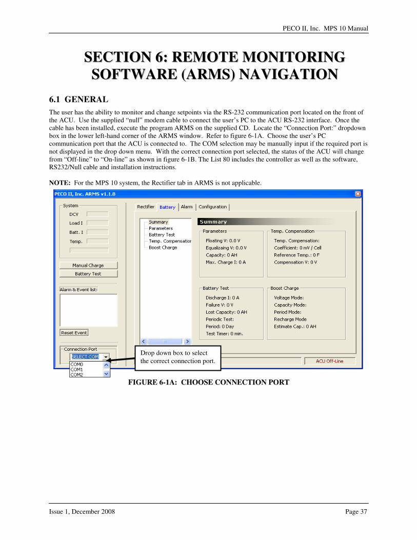
The user has the ability to monitor and change setpoints via the RS-232 communication port located on the front of the ACU. Use the supplied “null” modem cable to connect the user’s PC to the ACU RS-232 interface. Once the cable has been installed, execute the program ARMS on the supplied CD. Locate the “Connection Port:” dropdown box in the lower left-hand corner of the ARMS window. Refer to figure 6-1A. Choose the user’s PC communication port that the ACU is connected to. The COM selection may be manually input if the required port is not displayed in the drop down menu. With the correct connection port selected, the status of the ACU will change from “Off-line” to “On-line” as shown in figure 6-1B. The List 80 includes the controller as well as the software, RS232/Null cable and installation instructions. NOTE: For the MPS 10 system, the Rectifier tab in ARMS is not applicable.
FIGURE 6-1A: CHOOSE CONNECTION PORT
Drop down box to select the correct connection port.

FIGURE 6-1B: ACU ON-LINE
ACU On-Line indicates that the controller is communicating with the ARMS software
PECO II, Inc. MPS 10 Manual
Issue 1, December 2008 Page 39
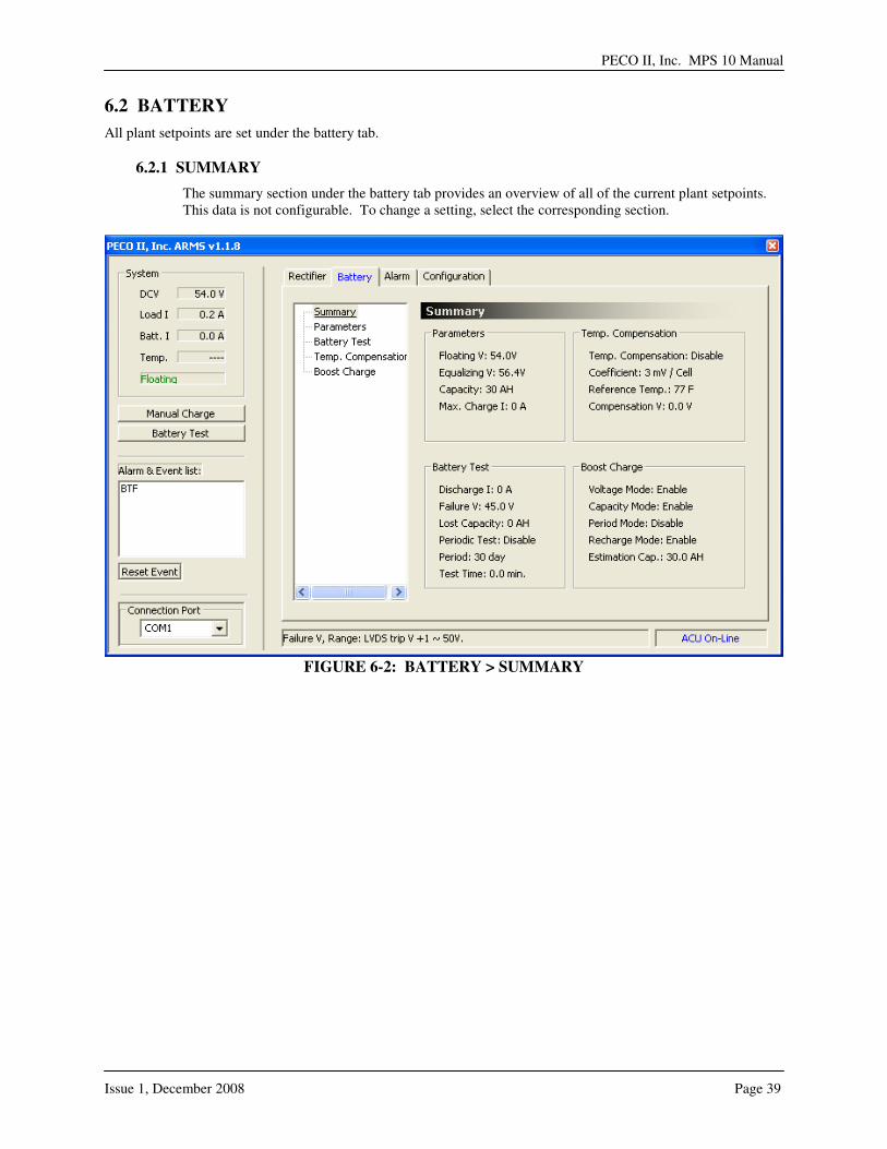
6.2 BATTERY
All plant setpoints are set under the battery tab.
6.2.1 SUMMARY
The summary section under the battery tab provides an overview of all of the current plant setpoints. This data is not configurable. To change a setting, select the corresponding section.
FIGURE 6-2: BATTERY > SUMMARY
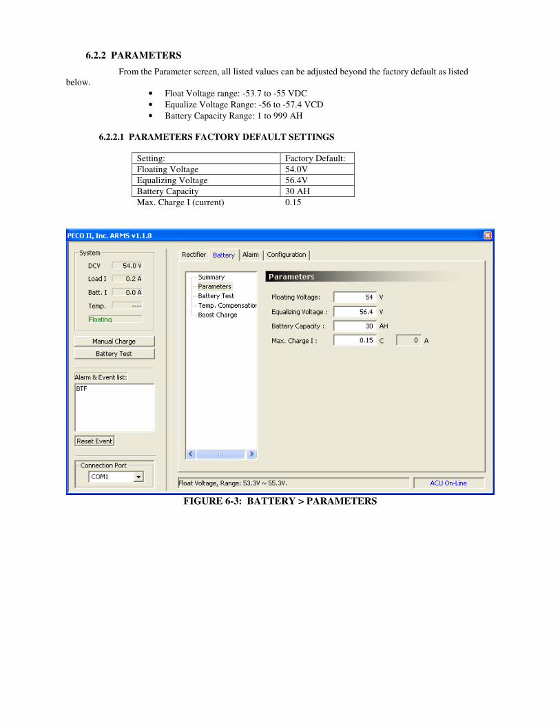
6.2.2 PARAMETERS
From the Parameter screen, all listed values can be adjusted beyond the factory default as listed below.
• Float Voltage range: -53.7 to -55 VDC
• Equalize Voltage Range: -56 to -57.4 VCD
• Battery Capacity Range: 1 to 999 AH
6.2.2.1 PARAMETERS FACTORY DEFAULT SETTINGS
Setting: Factory Default:
Floating Voltage 54.0V
Equalizing Voltage 56.4V
Battery Capacity 30 AH
Max. Charge I (current) 0.15
FIGURE 6-3: BATTERY > PARAMETERS
PECO II, Inc. MPS 10 Manual
Issue 1, December 2008 Page 41
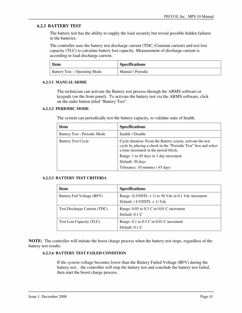
6.2.3 BATTERY TEST
The battery test has the ability to supply the load securely but reveal possible hidden failures in the batteries.
The controller uses the battery test discharge current (TDC, Constant current) and test lost capacity (TLC) to calculate battery lost capacity. Measurement of discharge current is according to load discharge current.
Item Specifications
Battery Test – Operating Mode Manual / Periodic
6.2.3.1 MANUAL MODE
The technician can activate the Battery test process through the ARMS software or keypads (on the front panel). To activate the battery test via the ARMS software, click on the radio button titled “Battery Test”.
6.2.3.2 PERIODIC MODE
The system can periodically test the battery capacity, to validate state of health.
Item Specifications
Battery Test - Periodic Mode Enable / Disable
Battery Test Cycle Cycle duration: From the Battery screen, activate the test cycle by placing a check in the “Periodic Test” box and select a time increment in the period block.
Range: 1 to 45 days in 1 day increment
Default: 30 days
Tolerance: 10 minutes / 45 days
6.2.3.3 BATTERY TEST CRITERIA
Item Specifications
Battery Fail Voltage (BFV) Range: (LVDSTL + 1) to 50 Vdc in 0.1 Vdc increment
Default: ( LVDSTL + 1) Vdc
Test Discharge Current (TDC) Range: 0.05 to 0.3 C in 0.01 C increment
Default: 0.1 C
Test Lost Capacity (TLC) Range: 0.1 to 0.5 C in 0.01 C increment
Default: 0.1 C
NOTE: The controller will initiate the boost charge process when the battery test stops, regardless of the battery test results.
6.2.3.4 BATTERY TEST FAILED CONDITION
If the system voltage becomes lower than the Battery Failed Voltage (BFV) during the battery test , the controller will stop the battery test and conclude the battery test failed, then start the boost charge process.

6.2.3.4 BATTERY TEST PASSED CONDITION
If the battery test duration time equals 10.5 hours or greater, the controller will stop the battery test and conclude the battery test was ok, then start the boost charge process.
FIGURE 6-4: BATTERY > BATTERY TEST
PECO II, Inc. MPS 10 Manual
Issue 1, December 2008 Page 43
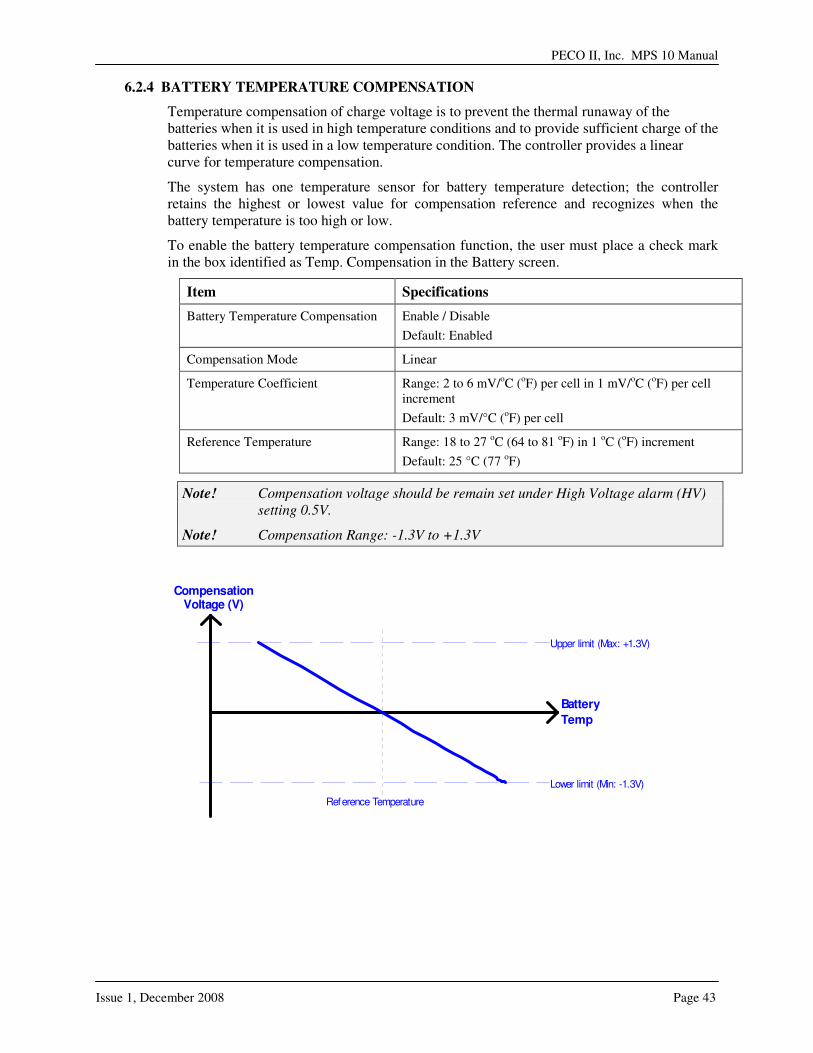
6.2.4 BATTERY TEMPERATURE COMPENSATION
Temperature compensation of charge voltage is to prevent the thermal runaway of the batteries when it is used in high temperature conditions and to provide sufficient charge of the batteries when it is used in a low temperature condition. The controller provides a linear curve for temperature compensation.
The system has one temperature sensor for battery temperature detection; the controller retains the highest or lowest value for compensation reference and recognizes when the battery temperature is too high or low.
To enable the battery temperature compensation function, the user must place a check mark in the box identified as Temp. Compensation in the Battery screen.
Item Specifications
Battery Temperature Compensation Enable / Disable
Default: Enabled
Compensation Mode Linear
Temperature Coefficient Range: 2 to 6 mV/oC (oF) per cell in 1 mV/oC (oF) per cell increment
Default: 3 mV/°C (oF) per cell
Reference Temperature Range: 18 to 27 oC (64 to 81 oF) in 1 oC (oF) increment
Default: 25 °C (77 oF)
Note! Compensation voltage should be remain set under High Voltage alarm (HV)
setting 0.5V.
Note! Compensation Range: -1.3V to +1.3V
Upper limit (Max: +1.3V)
Battery
Temp
CompensationVoltage (V)
Lower limit (Min: -1.3V)
Reference Temperature

FIGURE 6-5: BATTERY > TEMPERATURE COMPENSATION
6.2.5 BOOST CHARGE
Whenever the batteries are deeply discharged (AC fail or battery test), the system will start a boost charge sequence if the system is able to recharge the batteries. The user may select any of the listed criteria by populating the check box. If no selection is made, the boost charge process is inactive.
Item Specifications
Boost Charge – Start Mode When the battery state switches from discharge to recharge mode, the system will initiate the boost charge function if any of the following conditions have been selected.
1. Voltage Mode:
2. Capacity Mode
3. Recharge Mode
4. Periodic mode

PECO II, Inc. MPS 10 Manual
Issue 1, December 2008 Page 45
FIGURE 6-6: BATTERY > BOOST CHARGE
6.2.5.1 VOLTAGE MODE
Item Specifications
Voltage Mode Enable / Disable
Deep Discharge Voltage (DDV)
System voltage is lower than DDV, start boost charge process.
Target voltage = Equalize voltage (EQUV)
Range: 44.0 to 48.0 Vdc in 0.1 Vdc increment
Default: 46.0 Vdc
Tolerance: 2 %
6.2.5.2 CAPACITY MODE
Item Specifications
Capacity Mode Enable / Disable
Remaining Battery Capacity (RBC)
Whenever a system failure has occurred and battery capacity is lower than RBC, the boost sequence will begin.
RBC = (C - �tdc * Discharge I + �tc * Charge I)/C; RBC�1
C= Battery capacity, �tdc=Discharge time, �tc=Charge time
Target voltage = Equalize voltage (EQUV)
Range: 0.50 to 0.95 C in 0.01 C increment
Default: 0.95 C
Tolerance: 2 %
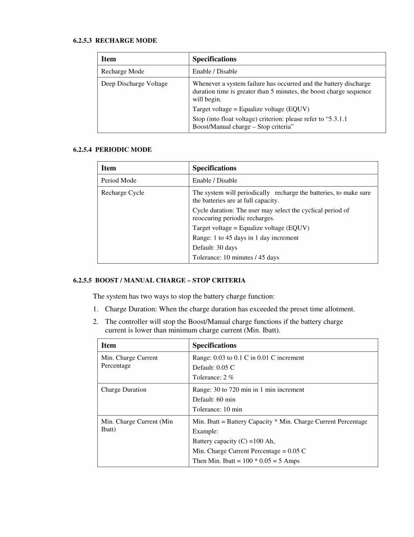
6.2.5.3 RECHARGE MODE
Item Specifications
Recharge Mode Enable / Disable
Deep Discharge Voltage Whenever a system failure has occurred and the battery discharge duration time is greater than 5 minutes, the boost charge sequence will begin.
Target voltage = Equalize voltage (EQUV)
Stop (into float voltage) criterion: please refer to “5.3.1.1 Boost/Manual charge – Stop criteria”
6.2.5.4 PERIODIC MODE
Item Specifications
Period Mode Enable / Disable
Recharge Cycle The system will periodically recharge the batteries, to make sure the batteries are at full capacity.
Cycle duration: The user may select the cyclical period of reoccuring periodic recharges.
Target voltage = Equalize voltage (EQUV)
Range: 1 to 45 days in 1 day increment
Default: 30 days
Tolerance: 10 minutes / 45 days
6.2.5.5 BOOST / MANUAL CHARGE – STOP CRITERIA
The system has two ways to stop the battery charge function:
1. Charge Duration: When the charge duration has exceeded the preset time allotment.
2. The controller will stop the Boost/Manual charge functions if the battery charge current is lower than minimum charge current (Min. Ibatt).
Item Specifications
Min. Charge Current Percentage
Range: 0.03 to 0.1 C in 0.01 C increment
Default: 0.05 C
Tolerance: 2 %
Charge Duration Range: 30 to 720 min in 1 min increment
Default: 60 min
Tolerance: 10 min
Min. Charge Current (Min Ibatt)
Min. Ibatt = Battery Capacity * Min. Charge Current Percentage
Example:
Battery capacity (C) =100 Ah,
Min. Charge Current Percentage = 0.05 C
Then Min. Ibatt = 100 * 0.05 = 5 Amps

PECO II, Inc. MPS 10 Manual
Issue 1, December 2008 Page 47
6.3 ALARM PARAMETER SETTINGS
This section defines all of the system alarms and conditions of alarm relays.
The user can change the alarm settings through the ARMS software.
NOTE: If the L90 SNMP alarm card is equipped, do not change any of the factory alarm settings.
Refer to table 6-1 for the alarm conditions and acronyms.
6.3.1 DC ALARMS
DC voltage alarms are a condition of either low DC voltage or high DC voltage. The setpoint window is based on the system default and available ranges defined in the following chart. To change a setpoint, click on the setting and enter the new setpoint.
Item Specifications
DC Low Voltage Alarm (DCL) Range: (LVDSTL + 2) to 50 Vdc in 0.1 Vdc increment
Default: (LVDS1TL + 2Vdc) Factory Set at 46.0Vdc
Tolerance: 0.1 Vdc
DC High Voltage Alarm (DCH) Range: (EQUV + 0.2) to (HVSD - 0.3V) Vdc in 0.1 Vdc increment
Default: 58.0 Vdc
Tolerance: 0.1 Vdc
FIGURE 6-6: ALARM > DC ALARM
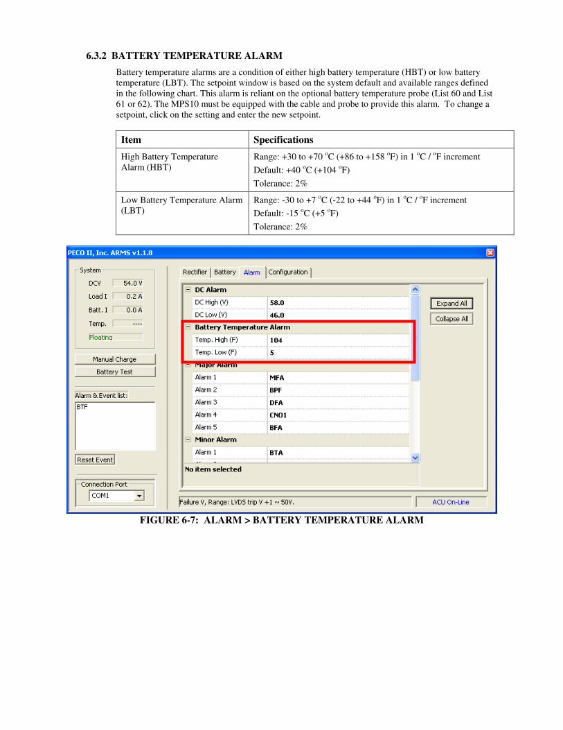
6.3.2 BATTERY TEMPERATURE ALARM
Battery temperature alarms are a condition of either high battery temperature (HBT) or low battery temperature (LBT). The setpoint window is based on the system default and available ranges defined in the following chart. This alarm is reliant on the optional battery temperature probe (List 60 and List 61 or 62). The MPS10 must be equipped with the cable and probe to provide this alarm. To change a setpoint, click on the setting and enter the new setpoint.
Item Specifications
High Battery Temperature Alarm (HBT)
Range: +30 to +70 oC (+86 to +158 oF) in 1 oC / oF increment
Default: +40 oC (+104 oF)
Tolerance: 2%
Low Battery Temperature Alarm (LBT)
Range: -30 to +7 oC (-22 to +44 oF) in 1 oC / oF increment
Default: -15 oC (+5 oF)
Tolerance: 2%
FIGURE 6-7: ALARM > BATTERY TEMPERATURE ALARM
PECO II, Inc. MPS 10 Manual
Issue 1, December 2008 Page 49
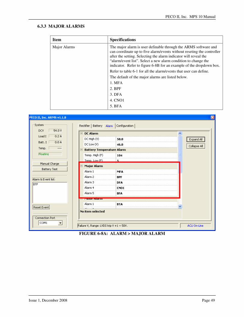
6.3.3 MAJOR ALARMS
Item Specifications
Major Alarms The major alarm is user definable through the ARMS software and can coordinate up to five alarm/events without reseting the controller after the setting. Selecting the alarm indicator will reveal the “alarm/event list”. Select a new alarm condition to change the indicator. Refer to figure 6-8B for an example of the dropdown box.
Refer to table 6-1 for all the alarm/events that user can define.
The default of the major alarms are listed below.
1. MFA
2. BPF
3. DFA
4. CNO1
5. BFA
FIGURE 6-8A: ALARM > MAJOR ALARM

FIGURE 6-8B: ALARM > MAJOR ALARM

PECO II, Inc. MPS 10 Manual
Issue 1, December 2008 Page 51
6.3.4 MINOR ALARMS
Item Specifications
Minor Alarms The minor alarm is user definable through the ARMS software and can coordinate up to five alarm/events without reseting the controller after the setting. Selecting the alarm indicator will reveal the “alarm/event list”. Select a new alarm condition to change the indicator. Refer to figure 6-9B for an example of the dropdown box.
Refer to table 6-1 for all the alarm/events that user can define.
The default of the minor alarms are listed below.
1. BTA
2. ACF
3. RFA
4. HFV
5. BDD
FIGURE 6-9A: ALARM > MINOR ALARM

FIGURE 6-9B: ALARM > MINOR ALARM
PECO II, Inc. MPS 10 Manual
Issue 1, December 2008 Page 53
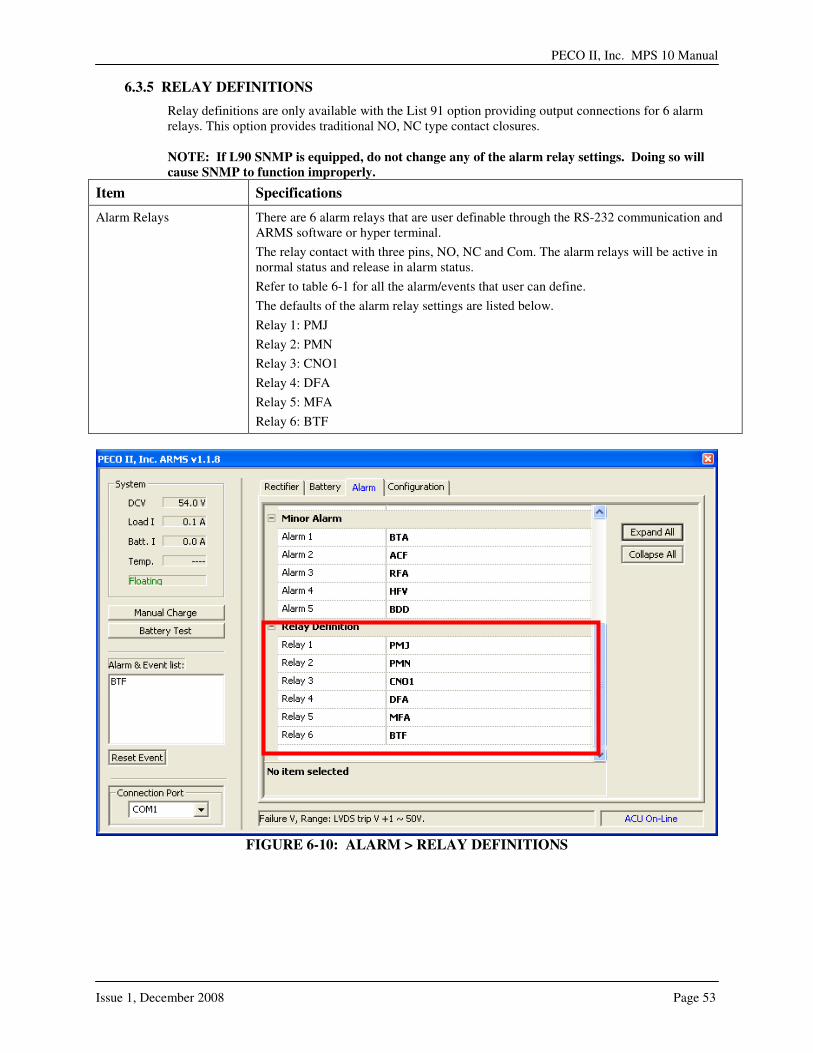
6.3.5 RELAY DEFINITIONS
Relay definitions are only available with the List 91 option providing output connections for 6 alarm relays. This option provides traditional NO, NC type contact closures. NOTE: If L90 SNMP is equipped, do not change any of the alarm relay settings. Doing so will
cause SNMP to function improperly.
Item Specifications
Alarm Relays There are 6 alarm relays that are user definable through the RS-232 communication and ARMS software or hyper terminal.
The relay contact with three pins, NO, NC and Com. The alarm relays will be active in normal status and release in alarm status.
Refer to table 6-1 for all the alarm/events that user can define.
The defaults of the alarm relay settings are listed below.
Relay 1: PMJ
Relay 2: PMN
Relay 3: CNO1
Relay 4: DFA
Relay 5: MFA
Relay 6: BTF
FIGURE 6-10: ALARM > RELAY DEFINITIONS

TABLE 6-1: ALARM CONDITIONS AND ACRONYMS
ACRONYM ALARM CONDITION
ACA AC Abnormal The AC mains voltage is out of normal operating range
ACF AC Fail The ACU is assuming an AC failure because all rectifiers are off and the system is operating on batteries. Additionally, the AC mains voltage may be out of normal operating range.
BDA Battery Discharge Alarm Indicates that the batteries are in a discharge state.
BDD Battery Deeply Discharge
The plant voltage is below the threshold set for BD in the present plant mode, FLOAT or BOOST/BTP. This alarm will not retire immediately upon rectifier restoration after an extended discharge. The plant voltage will not fully recover until the batteries depleted energy has been replaced. Do NOT adjust the rectifier voltage adjustments if they are at or near rated output currents.
BFA Battery Test Failed During a battery test, if the system voltage exceeds the battery failed voltage threshold, the controller will stop the battery test and conclude that the battery test has failed. The boost charge process will initialize.
BIN Battery Test Interruption During a battery test, if the user manually interrupts a battery test, this alarm will be active.
BOK Battery Test Passed Indicates that the battery test has passed.
BPF Battery Power Fuse Indicates that the battery disconnect fuse is open (an indicator will also illuminate on the front of the manual battery fuse disconnect on the front of the system). The batteries are disconnected from the plant as a result.
BTA Battery High Temperature The battery temperature (probe) is higher than the battery high temperature alarm threshold setpoint.
BTF Battery Temperature Fail
A condition that indicates that the battery temperature value is abnormal (>195 degree F or < -40 degrees F). The BTF may also indicate that no battery temperature sensor is installed or that the battery temperature sensor wire is broken.
BTS Battery Test Active Indicates that a battery test is in process.
CLM Rectifier Current Limit The rectifiers connected to the controller’s serial bus have reached their current limit setting. Plant voltage may, therefore, be lower than that requested in Rectifier Manager.
CNO1 Low Voltage Disconnect 1
Either the batteries have been disconnected from the charge bus or the load has been disconnected from the discharge bus due to the plant voltage being less than the LVD alarm threshold.
CNO2 Low Voltage Disconnect 2
Either the batteries have been disconnected from the charge bus or the load has been disconnected from the discharge bus due to the plant voltage being less than the LVD alarm threshold.
CNO3 Low Voltage Disconnect 3
Either the batteries have been disconnected from the charge bus or the load has been disconnected from the discharge bus due to the plant voltage being less than the LVD alarm threshold.
CNOX Low Voltage Disconnect 1 – 3 (Any one disconnection)
Either the batteries have been disconnected from the charge bus or the load has been disconnected from the discharge bus due to the plant voltage being less than the LVD alarm threshold.
DFA Distribution Fuse Fail A fuse or CB alarm is active in the plant distribution circuit.
EQU Equalize The plant is currently charging the batteries at the equalize voltage setpoint.

PECO II, Inc. MPS 10 Manual
Issue 1, December 2008 Page 55
HFV High Float Voltage Plant voltage has exceeded the controller threshold for this alarm. The HFV threshold should be set lower than the HVA threshold which causes an HVSD signal to be issued to plant rectifiers.
HVA Very High Voltage The plant voltage has exceeded the controller threshold for this alarm. The HVA alarm causes a HVSD signal to be issued to plant rectifiers.
MFA Multiple Rectifier Fail Multiple rectifiers are not capable of delivering full rated current to the load.
PMJ Power Major Customer configured grouping meant to contain abnormal operating conditions that will affect power to the load, or a failure with the potential for masking a service-affecting problem.
PMN Power Minor Customer configured grouping meant to contain abnormal operating conditions in the power system that requires attention, but does not affect power to the load.
RFA Rectifier Fail A single rectifier is not capable of delivering full rated current to the load.
Undefined Undefined This is a placeholder only. It is to indicate that the point is not defined

6.4 CONFIGURATION
FIGURE 6-11: CONFIGURATION > LVDS FUNCTION
FIGURE 6-12: CONFIGURATION > LVDS SETTINGS
6.4.1 LVDS FUNCTION
The controller can activate one LVD, for either battery or load based on voltage, temperature, or both. To change a factory setting, click on “Setting…” (refer to figure 6-11). This will open another window (refer to figure 6-12) where the setpoints may be changed.
LVD (Low Voltage Disconnects Switch) is used to disconnect either the load from the system (low voltage disconnect) or the battery (battery low voltage disconnect) when the battery has been completely discharged in a long duration power outage or battery temperature is too
Click on “Setting…” to open the LVDS Setting window. Refer to figure 6-12.
PECO II, Inc. MPS 10 Manual
Issue 1, December 2008 Page 57
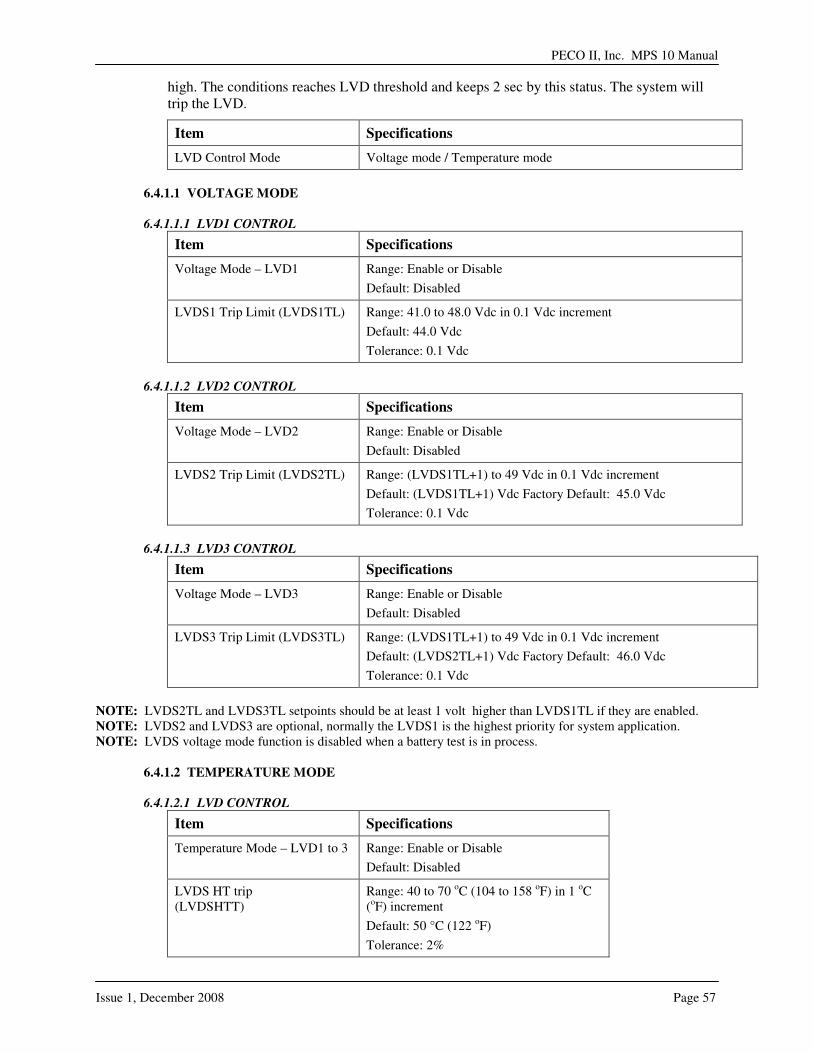
high. The conditions reaches LVD threshold and keeps 2 sec by this status. The system will trip the LVD.
Item Specifications
LVD Control Mode Voltage mode / Temperature mode
6.4.1.1 VOLTAGE MODE
6.4.1.1.1 LVD1 CONTROL
Item Specifications
Voltage Mode – LVD1 Range: Enable or Disable
Default: Disabled
LVDS1 Trip Limit (LVDS1TL) Range: 41.0 to 48.0 Vdc in 0.1 Vdc increment
Default: 44.0 Vdc
Tolerance: 0.1 Vdc
6.4.1.1.2 LVD2 CONTROL
Item Specifications
Voltage Mode – LVD2 Range: Enable or Disable
Default: Disabled
LVDS2 Trip Limit (LVDS2TL) Range: (LVDS1TL+1) to 49 Vdc in 0.1 Vdc increment
Default: (LVDS1TL+1) Vdc Factory Default: 45.0 Vdc
Tolerance: 0.1 Vdc
6.4.1.1.3 LVD3 CONTROL
Item Specifications
Voltage Mode – LVD3 Range: Enable or Disable
Default: Disabled
LVDS3 Trip Limit (LVDS3TL) Range: (LVDS1TL+1) to 49 Vdc in 0.1 Vdc increment
Default: (LVDS2TL+1) Vdc Factory Default: 46.0 Vdc
Tolerance: 0.1 Vdc
NOTE: LVDS2TL and LVDS3TL setpoints should be at least 1 volt higher than LVDS1TL if they are enabled. NOTE: LVDS2 and LVDS3 are optional, normally the LVDS1 is the highest priority for system application. NOTE: LVDS voltage mode function is disabled when a battery test is in process.
6.4.1.2 TEMPERATURE MODE
6.4.1.2.1 LVD CONTROL
Item Specifications
Temperature Mode – LVD1 to 3 Range: Enable or Disable
Default: Disabled
LVDS HT trip (LVDSHTT)
Range: 40 to 70 oC (104 to 158 oF) in 1 oC (oF) increment
Default: 50 °C (122 oF)
Tolerance: 2%

-This page intentionally left blank-
PECO II, Inc. MPS 10 Manual
Issue 1, December 2008 Page 59
SSEECCTTIIOONN 77:: SSNNMMPP SSEETTUUPP
7.1 GENERAL
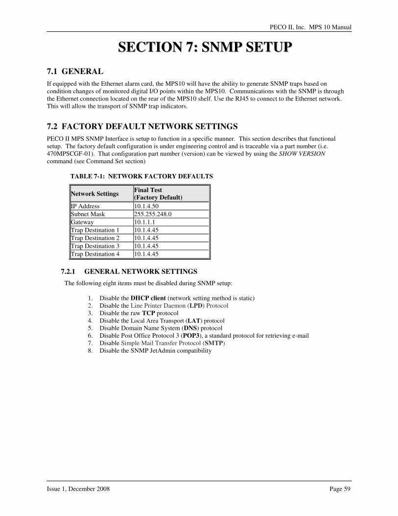
If equipped with the Ethernet alarm card, the MPS10 will have the ability to generate SNMP traps based on condition changes of monitored digital I/O points within the MPS10. Communications with the SNMP is through the Ethernet connection located on the rear of the MPS10 shelf. Use the RJ45 to connect to the Ethernet network. This will allow the transport of SNMP trap indicators.
7.2 FACTORY DEFAULT NETWORK SETTINGS
PECO II MPS SNMP Interface is setup to function in a specific manner. This section describes that functional setup. The factory default configuration is under engineering control and is traceable via a part number (i.e. 470MPSCGF-01). That configuration part number (version) can be viewed by using the SHOW VERSION command (see Command Set section)
TABLE 7-1: NETWORK FACTORY DEFAULTS
Network Settings Final Test
(Factory Default)
IP Address 10.1.4.50
Subnet Mask 255.255.248.0
Gateway 10.1.1.1
Trap Destination 1 10.1.4.45
Trap Destination 2 10.1.4.45
Trap Destination 3 10.1.4.45
Trap Destination 4 10.1.4.45
7.2.1 GENERAL NETWORK SETTINGS
The following eight items must be disabled during SNMP setup:
1. Disable the DHCP client (network setting method is static) 2. Disable the Line Printer Daemon (LPD) Protocol 3. Disable the raw TCP protocol 4. Disable the Local Area Transport (LAT) protocol 5. Disable Domain Name System (DNS) protocol 6. Disable Post Office Protocol 3 (POP3), a standard protocol for retrieving e-mail 7. Disable Simple Mail Transfer Protocol (SMTP) 8. Disable the SNMP JetAdmin compatibility

7.3 SNMP TRAP DETAILS
GPIO
Input
State
Change
SNMP
Trap
Number
SNMP
Trap
Version
Enterprise
(OID) Name
Alarm
Definitions
SNMP
Destinations (1 thru 4)
0 to 1 17 1.3.6.1.4.1.1240.2.3.5.6 trapMajAlarmRetire 10.1.4.45 1
1 to 0 25 1.3.6.1.4.1.1240.2.3.5.6 trapMajAlarmActive Major Alarm
10.1.4.45
0 to 1 18 1.3.6.1.4.1.1240.2.3.5.6 trapMinAlarmRetire 10.1.4.45 2
1 to 0 26 1.3.6.1.4.1.1240.2.3.5.6 trapMinAlarmActive Minor Alarm
10.1.4.45
0 to 1 19 1.3.6.1.4.1.1240.2.3.5.6 trapLvdsAlarmRetire 10.1.4.45 3
1 to 0 27 1.3.6.1.4.1.1240.2.3.5.6 trapLvdsAlarmActive LVDS Alarm
10.1.4.45
0 to 1 20 1.3.6.1.4.1.1240.2.3.5.6 trapFuseAlarmRetire 10.1.4.45 4
1 to 0 28 1.3.6.1.4.1.1240.2.3.5.6 trapFuseAlarmActive Fuse Alarm
10.1.4.45
0 to 1 21 1.3.6.1.4.1.1240.2.3.5.6 trapRfaRetire 10.1.4.45 5
1 to 0 29 1.3.6.1.4.1.1240.2.3.5.6 trapRfaActive RFA Alarm
10.1.4.45
0 to 1 22 1.3.6.1.4.1.1240.2.3.5.6 trapTempAlarmRetire 10.1.4.45 6
1 to 0 30
1
1.3.6.1.4.1.1240.2.3.5.6 trapTempAlarmActive
Temperature Alarm 10.1.4.45
7.4 USER INTERFACE - CUSTOMIZE SETTINGS VIA TELNET SESSION
The PECO II MPS10 SNMP interface can be accessed using a telnet session via an Ethernet connection. Note: It is critical that the end user maintain a record of the unit’s IP address if it is set to something other than the factory default. The internal command console provides a sophisticated command line interface for advanced users to configure the PECO II MPS10 SNMP interface.
7.4.1 From the Windows Command Prompt (MS-DOS Prompt), Mac OS X Terminal Utility, or UNIX/Linux command line, enter the command telnet aa.bb.cc.dd and Press <ENTER>: (aa.bb.cc.dd is the IP address of the PECO II MPS10 SNMP interface.)
FIGURE 7-1: START A TELNET SESSION
PECO II, Inc. MPS 10 Manual
Issue 1, December 2008 Page 61
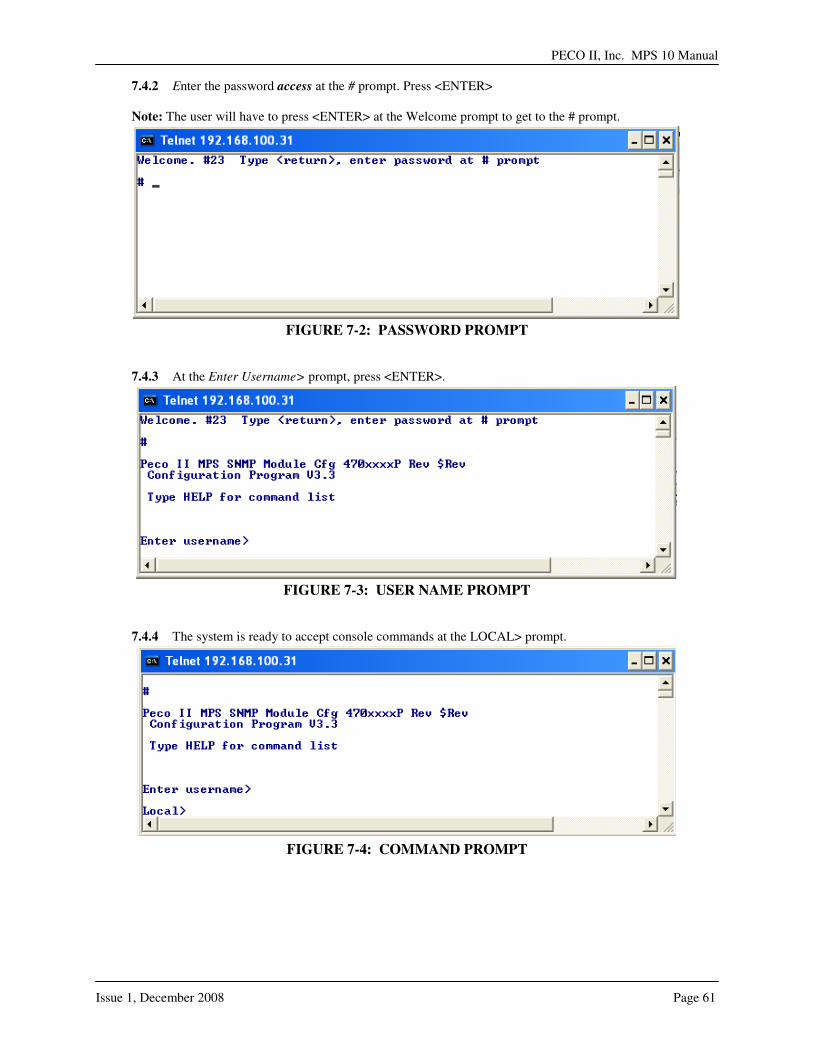
7.4.2 Enter the password access at the # prompt. Press <ENTER>
Note: The user will have to press <ENTER> at the Welcome prompt to get to the # prompt.
FIGURE 7-2: PASSWORD PROMPT
7.4.3 At the Enter Username> prompt, press <ENTER>.
FIGURE 7-3: USER NAME PROMPT
7.4.4 The system is ready to accept console commands at the LOCAL> prompt.
FIGURE 7-4: COMMAND PROMPT
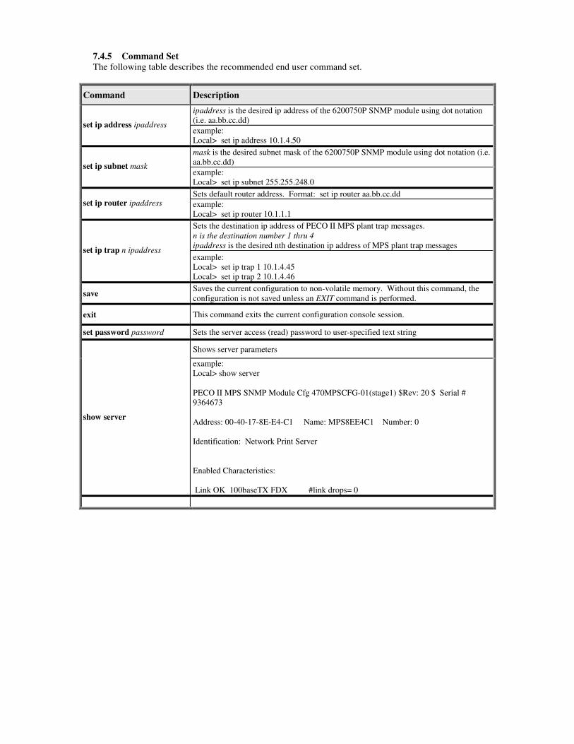
7.4.5 Command Set
The following table describes the recommended end user command set.
Command Description
ipaddress is the desired ip address of the 6200750P SNMP module using dot notation (i.e. aa.bb.cc.dd)
set ip address ipaddress example: Local> set ip address 10.1.4.50
mask is the desired subnet mask of the 6200750P SNMP module using dot notation (i.e. aa.bb.cc.dd)
set ip subnet mask example: Local> set ip subnet 255.255.248.0
Sets default router address. Format: set ip router aa.bb.cc.dd set ip router ipaddress example:
Local> set ip router 10.1.1.1
Sets the destination ip address of PECO II MPS plant trap messages. n is the destination number 1 thru 4
ipaddress is the desired nth destination ip address of MPS plant trap messages set ip trap n ipaddress
example: Local> set ip trap 1 10.1.4.45 Local> set ip trap 2 10.1.4.46
save Saves the current configuration to non-volatile memory. Without this command, the configuration is not saved unless an EXIT command is performed.
exit This command exits the current configuration console session.
set password password Sets the server access (read) password to user-specified text string
Shows server parameters
show server
example: Local> show server PECO II MPS SNMP Module Cfg 470MPSCFG-01(stage1) $Rev: 20 $ Serial # 9364673 Address: 00-40-17-8E-E4-C1 Name: MPS8EE4C1 Number: 0 Identification: Network Print Server Enabled Characteristics: Link OK 100baseTX FDX #link drops= 0

PECO II, Inc. MPS 10 Manual
Issue 1, December 2008 Page 63
Command Description
Shows TCP/IP related parameters
show ip
Local> show ip IP is enabled IP address 192.168.100.31 Boot tries 3 Subnet mask 255.255.248.0 Boot method STATIC IP Gateway 0.0.0.0 Max window 10240 (set manually) LPD banner disabled Timeout 1 min LPD retries are disabled Keepalive 0 min Service Port TCP port MPS8EE4C1_S1_A S1 9100 MPS8EE4C1_S1_B S1 3001
Shows firmware version of print server
show version
Local> show version PECO II MPS SNMP Module Cfg 470MPSCFG-01(final) $Rev: 20 $ Firmware Ver. BBES-1.26 (2008.05.02) Boot Ver. 2.0 32Mbit Flash
init Instructs the server to execute a soft reset when the next exit command is executed.
7.5 LED FUNCTIONALITY
FUNCTION STATE STATUS
On The module is receiving power Off The module is not receiving power Power
(Orange LED) Blinking
The module power supply is malfunctioning
Yellow Off Green Off
No network activity
Yellow On Green Off
10base-T network active
Yellow Blinking Green Off
10 base-T network data received
Yellow Off Green On
100base-TX network active
Yellow Off Green Blinking
100base-TX network data received
Yellow On Green On
Wireless network active, if WLAN model
Network Status (Yellow LED or Green LED)
Yellow Blinking Green Blinking
Wireless network data received, if WLAN model

-This page intentionally left blank-
PECO II, Inc. MPS 10 Manual
Issue 1, December 2008 Page 65
SSEECCTTIIOONN 88:: RREECCTTIIFFIIEERR SSPPEECCIIFFIICCAATTIIOONNSS
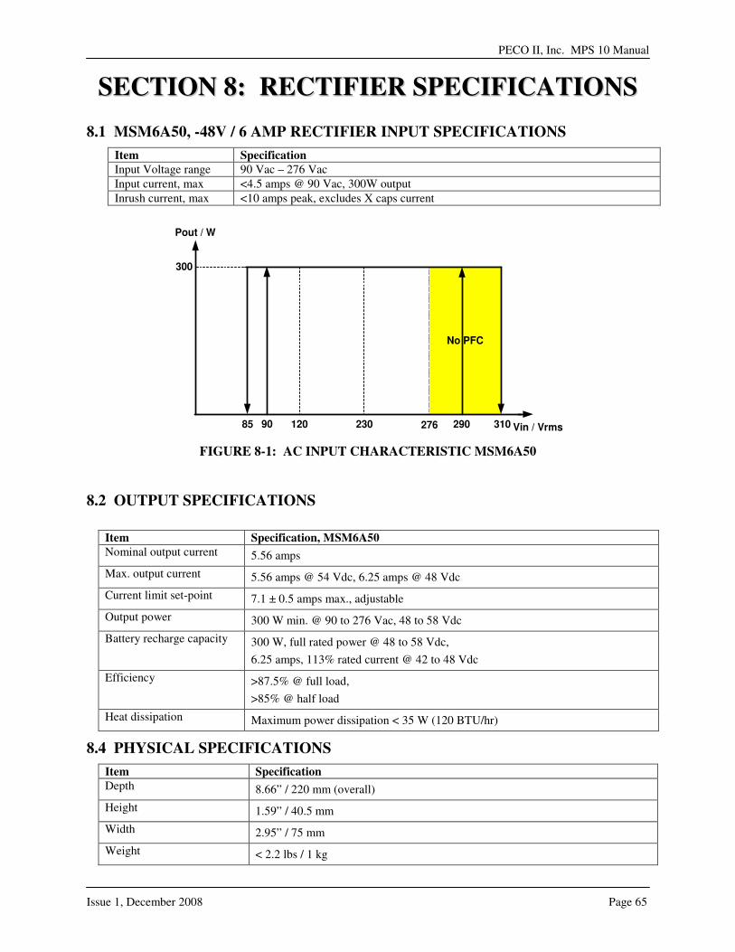
8.1 MSM6A50, -48V / 6 AMP RECTIFIER INPUT SPECIFICATIONS
Item Specification
Input Voltage range 90 Vac – 276 Vac
Input current, max <4.5 amps @ 90 Vac, 300W output
Inrush current, max <10 amps peak, excludes X caps current
No PFC
31085 290
300
Pout / W
230 Vin / Vrms27690 120
FIGURE 8-1: AC INPUT CHARACTERISTIC MSM6A50
8.2 OUTPUT SPECIFICATIONS
Item Specification, MSM6A50
Nominal output current 5.56 amps
Max. output current 5.56 amps @ 54 Vdc, 6.25 amps @ 48 Vdc
Current limit set-point 7.1 ± 0.5 amps max., adjustable
Output power 300 W min. @ 90 to 276 Vac, 48 to 58 Vdc
Battery recharge capacity 300 W, full rated power @ 48 to 58 Vdc,
6.25 amps, 113% rated current @ 42 to 48 Vdc
Efficiency >87.5% @ full load,
>85% @ half load
Heat dissipation Maximum power dissipation < 35 W (120 BTU/hr)
8.4 PHYSICAL SPECIFICATIONS
Item Specification
Depth 8.66” / 220 mm (overall)
Height 1.59” / 40.5 mm
Width 2.95” / 75 mm
Weight < 2.2 lbs / 1 kg
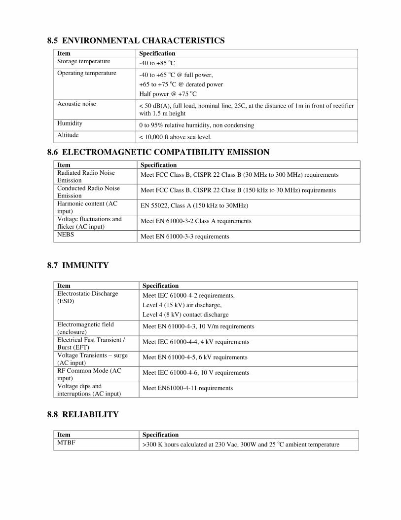
8.5 ENVIRONMENTAL CHARACTERISTICS
Item Specification
Storage temperature -40 to +85 oC
Operating temperature -40 to +65 oC @ full power,
+65 to +75 oC @ derated power
Half power @ +75 oC
Acoustic noise < 50 dB(A), full load, nominal line, 25C, at the distance of 1m in front of rectifier with 1.5 m height
Humidity 0 to 95% relative humidity, non condensing
Altitude < 10,000 ft above sea level.
8.6 ELECTROMAGNETIC COMPATIBILITY EMISSION
Item Specification
Radiated Radio Noise Emission
Meet FCC Class B, CISPR 22 Class B (30 MHz to 300 MHz) requirements
Conducted Radio Noise Emission
Meet FCC Class B, CISPR 22 Class B (150 kHz to 30 MHz) requirements
Harmonic content (AC input)
EN 55022, Class A (150 kHz to 30MHz)
Voltage fluctuations and flicker (AC input)
Meet EN 61000-3-2 Class A requirements
NEBS Meet EN 61000-3-3 requirements
8.7 IMMUNITY
Item Specification
Electrostatic Discharge (ESD)
Meet IEC 61000-4-2 requirements,
Level 4 (15 kV) air discharge,
Level 4 (8 kV) contact discharge
Electromagnetic field (enclosure)
Meet EN 61000-4-3, 10 V/m requirements
Electrical Fast Transient / Burst (EFT)
Meet IEC 61000-4-4, 4 kV requirements
Voltage Transients – surge (AC input)
Meet EN 61000-4-5, 6 kV requirements
RF Common Mode (AC input)
Meet IEC 61000-4-6, 10 V requirements
Voltage dips and interruptions (AC input)
Meet EN61000-4-11 requirements
8.8 RELIABILITY
Item Specification
MTBF >300 K hours calculated at 230 Vac, 300W and 25 oC ambient temperature
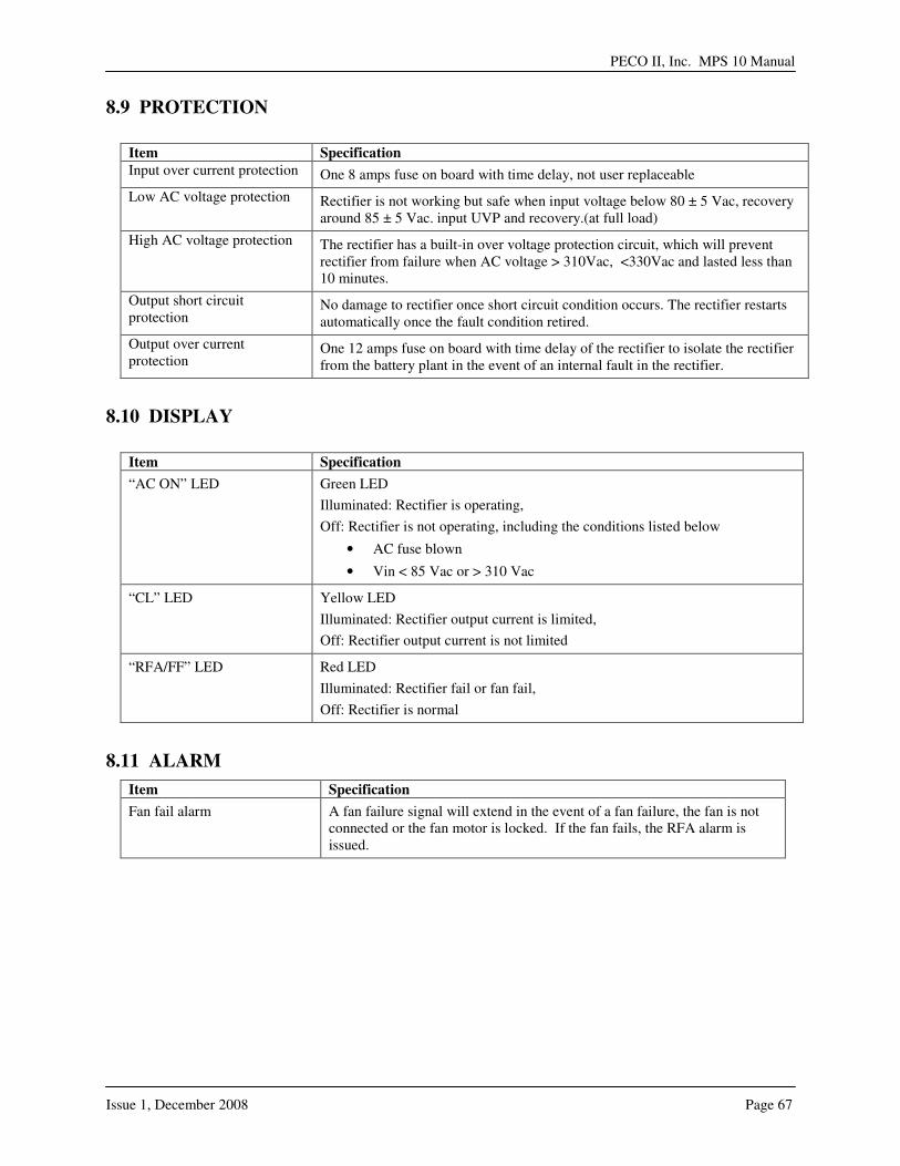
PECO II, Inc. MPS 10 Manual
Issue 1, December 2008 Page 67
8.9 PROTECTION
Item Specification
Input over current protection One 8 amps fuse on board with time delay, not user replaceable
Low AC voltage protection Rectifier is not working but safe when input voltage below 80 ± 5 Vac, recovery around 85 ± 5 Vac. input UVP and recovery.(at full load)
High AC voltage protection The rectifier has a built-in over voltage protection circuit, which will prevent rectifier from failure when AC voltage > 310Vac, <330Vac and lasted less than 10 minutes.
Output short circuit protection
No damage to rectifier once short circuit condition occurs. The rectifier restarts automatically once the fault condition retired.
Output over current protection
One 12 amps fuse on board with time delay of the rectifier to isolate the rectifier from the battery plant in the event of an internal fault in the rectifier.
8.10 DISPLAY
Item Specification
“AC ON” LED Green LED
Illuminated: Rectifier is operating,
Off: Rectifier is not operating, including the conditions listed below
• AC fuse blown
• Vin < 85 Vac or > 310 Vac
“CL” LED Yellow LED
Illuminated: Rectifier output current is limited,
Off: Rectifier output current is not limited
“RFA/FF” LED Red LED
Illuminated: Rectifier fail or fan fail,
Off: Rectifier is normal
8.11 ALARM
Item Specification
Fan fail alarm A fan failure signal will extend in the event of a fan failure, the fan is not connected or the fan motor is locked. If the fan fails, the RFA alarm is issued.
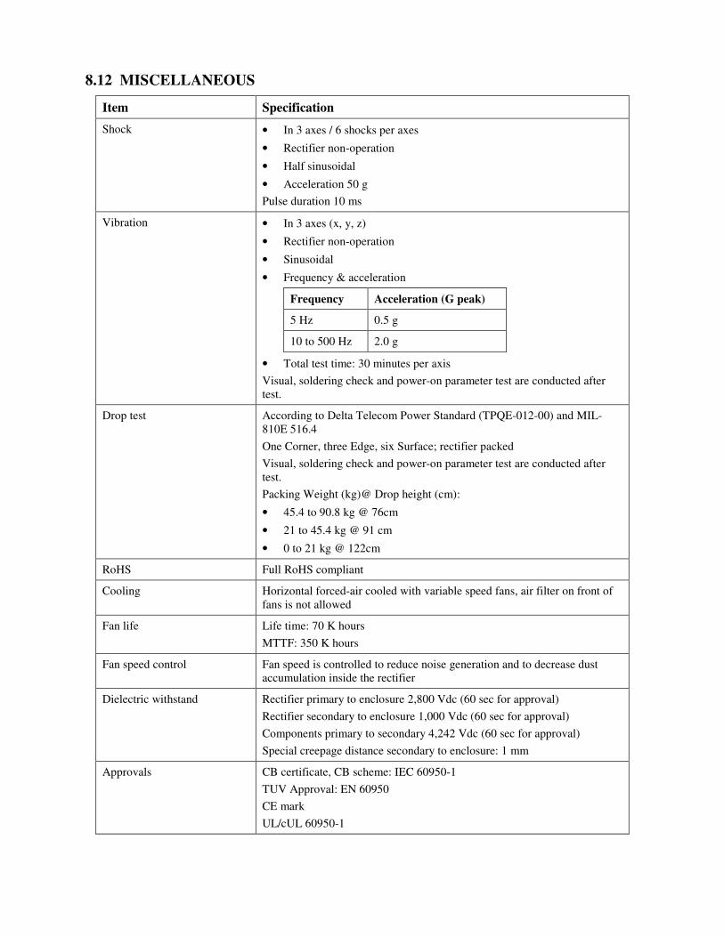
8.12 MISCELLANEOUS
Item Specification
Shock • In 3 axes / 6 shocks per axes
• Rectifier non-operation
• Half sinusoidal
• Acceleration 50 g
Pulse duration 10 ms
Vibration • In 3 axes (x, y, z)
• Rectifier non-operation
• Sinusoidal
• Frequency & acceleration
Frequency Acceleration (G peak)
5 Hz 0.5 g
10 to 500 Hz 2.0 g
• Total test time: 30 minutes per axis
Visual, soldering check and power-on parameter test are conducted after test.
Drop test According to Delta Telecom Power Standard (TPQE-012-00) and MIL-810E 516.4
One Corner, three Edge, six Surface; rectifier packed
Visual, soldering check and power-on parameter test are conducted after test.
Packing Weight (kg)@ Drop height (cm):
• 45.4 to 90.8 kg @ 76cm
• 21 to 45.4 kg @ 91 cm
• 0 to 21 kg @ 122cm
RoHS Full RoHS compliant
Cooling Horizontal forced-air cooled with variable speed fans, air filter on front of fans is not allowed
Fan life Life time: 70 K hours
MTTF: 350 K hours
Fan speed control Fan speed is controlled to reduce noise generation and to decrease dust accumulation inside the rectifier
Dielectric withstand Rectifier primary to enclosure 2,800 Vdc (60 sec for approval)
Rectifier secondary to enclosure 1,000 Vdc (60 sec for approval)
Components primary to secondary 4,242 Vdc (60 sec for approval)
Special creepage distance secondary to enclosure: 1 mm
Approvals CB certificate, CB scheme: IEC 60950-1
TUV Approval: EN 60950
CE mark
UL/cUL 60950-1

PECO II, Inc. MPS 10 Manual
Issue 1, December 2008 Page 69
SSEECCTTIIOONN 99:: RREEVVIISSIIOONN HHIISSTTOORRYY
Issue 1 Initial Release

-This page intentionally left blank-

PECO II, Inc. MPS 10 Manual
Issue 1, December 2008 Page 71
AATTTTAACCHHMMEENNTTSS

-This page intentionally left blank-
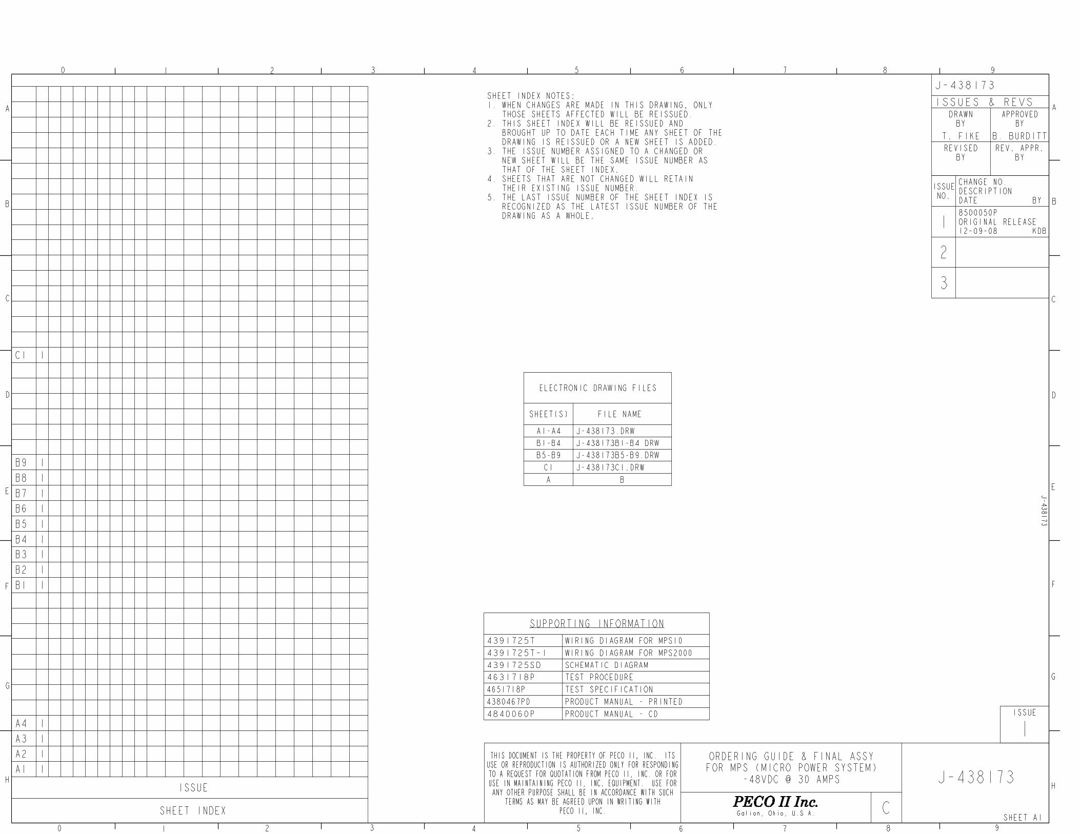
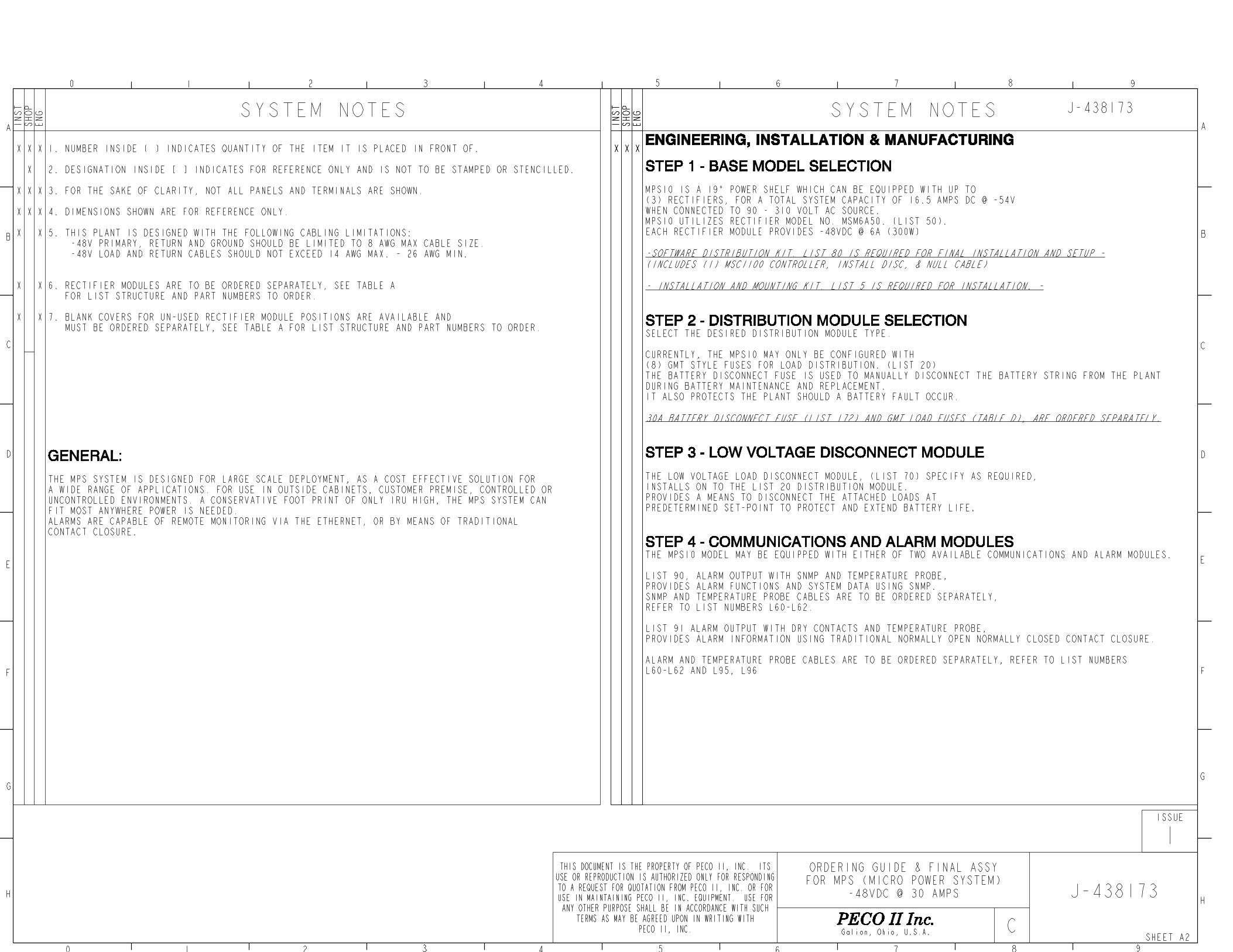
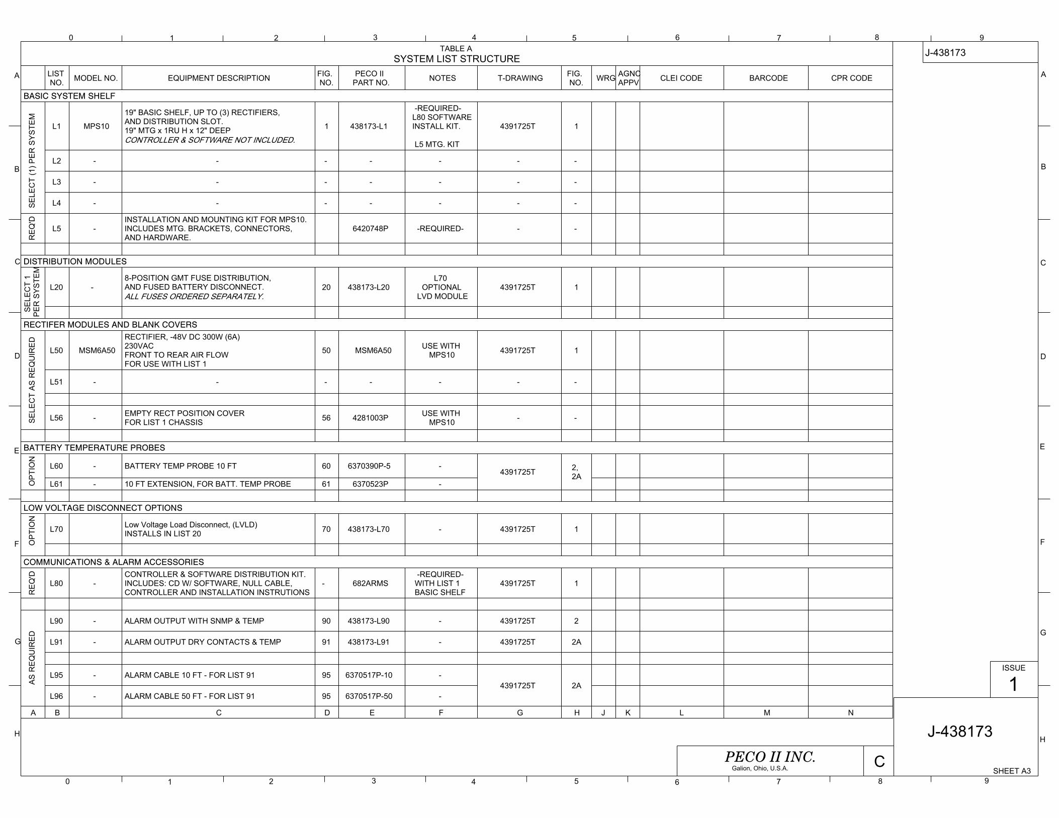
0 1 2 3 4 5 6 7 8 9
9876543210
A
B
C
D
E
F
G
H
A
B
C
D
E
F
G
H
SHEET A3
J-438173
ISSUE
1
CPECO II INC.Galion, Ohio, U.S.A.
TABLE ASYSTEM LIST STRUCTURE
LISTNO. MODEL NO. EQUIPMENT DESCRIPTION FIG.
NO.PECO II
PART NO. NOTES T-DRAWING FIG.NO. WRG AGNC
APPV CLEI CODE BARCODE CPR CODE
BASIC SYSTEM SHELF
SE
LEC
T (1
) PE
R S
YS
TEM
L1 MPS10
19" BASIC SHELF, UP TO (3) RECTIFIERS, AND DISTRIBUTION SLOT.19" MTG x 1RU H x 12" DEEPCONTROLLER & SOFTWARE NOT INCLUDED.
1 438173-L1
-REQUIRED- L80 SOFTWAREINSTALL KIT.
L5 MTG. KIT
4391725T 1
L2 - - - - - - -
L3 - - - - - - -
L4 - - - - - - -
RE
Q'D
L5 -INSTALLATION AND MOUNTING KIT FOR MPS10.INCLUDES MTG. BRACKETS, CONNECTORS,AND HARDWARE.
6420748P -REQUIRED- - -
DISTRIBUTION MODULES
SE
LEC
T 1
PE
R S
YS
TEM
L20 - 8-POSITION GMT FUSE DISTRIBUTION,AND FUSED BATTERY DISCONNECT.ALL FUSES ORDERED SEPARATELY.
20 438173-L20L70
OPTIONALLVD MODULE
4391725T 1
RECTIFER MODULES AND BLANK COVERS
SE
LEC
T A
S R
EQ
UIR
ED
L50 MSM6A50
RECTIFIER, -48V DC 300W (6A)230VACFRONT TO REAR AIR FLOWFOR USE WITH LIST 1
50 MSM6A50 USE WITHMPS10 4391725T 1
L51 - - - - - - -
L56 - EMPTY RECT POSITION COVER FOR LIST 1 CHASSIS 56 4281003P USE WITH
MPS10 - -
BATTERY TEMPERATURE PROBES
OP
TIO
N
L60 - BATTERY TEMP PROBE 10 FT 60 6370390P-5 -4391725T 2,
2AL61 - 10 FT EXTENSION, FOR BATT. TEMP PROBE 61 6370523P -
LOW VOLTAGE DISCONNECT OPTIONS
OP
TIO
N
L70 Low Voltage Load Disconnect, (LVLD)INSTALLS IN LIST 20 70 438173-L70 - 4391725T 1
COMMUNICATIONS & ALARM ACCESSORIES
RE
Q'D
L80 -CONTROLLER & SOFTWARE DISTRIBUTION KIT.INCLUDES: CD W/ SOFTWARE, NULL CABLE,CONTROLLER AND INSTALLATION INSTRUTIONS
- 682ARMS -REQUIRED-
WITH LIST 1BASIC SHELF
4391725T 1
AS
RE
QU
IRE
D
L90 - ALARM OUTPUT WITH SNMP & TEMP 90 438173-L90 - 4391725T 2
L91 - ALARM OUTPUT DRY CONTACTS & TEMP 91 438173-L91 - 4391725T 2A
L95 - ALARM CABLE 10 FT - FOR LIST 91 95 6370517P-10 -4391725T 2A
L96 - ALARM CABLE 50 FT - FOR LIST 91 95 6370517P-50 -
A B C D E F G H J K L M N
J-438173
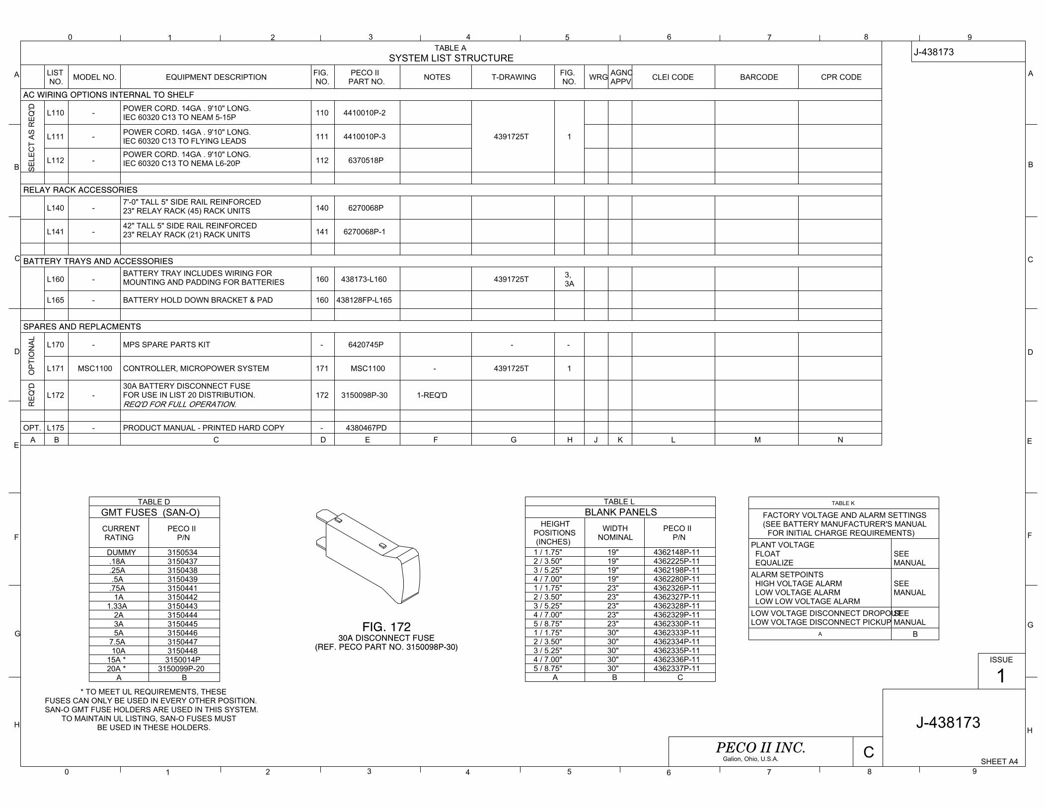
0 1 2 3 4 5 6 7 8 9
9876543210
A
B
C
D
E
F
G
H
A
B
C
D
E
F
G
H
SHEET A4
J-438173
ISSUE
1
CPECO II INC.Galion, Ohio, U.S.A.
TABLE ASYSTEM LIST STRUCTURE
LISTNO. MODEL NO. EQUIPMENT DESCRIPTION FIG.
NO.PECO II
PART NO. NOTES T-DRAWING FIG.NO. WRG AGNC
APPV CLEI CODE BARCODE CPR CODE
AC WIRING OPTIONS INTERNAL TO SHELF
SE
LEC
T A
S R
EQ
'D L110 - POWER CORD. 14GA . 9'10" LONG.IEC 60320 C13 TO NEAM 5-15P 110 4410010P-2
4391725T 1L111 - POWER CORD. 14GA . 9'10" LONG.IEC 60320 C13 TO FLYING LEADS 111 4410010P-3
L112 -POWER CORD. 14GA . 9'10" LONG.IEC 60320 C13 TO NEMA L6-20P 112 6370518P
RELAY RACK ACCESSORIES
L140 -7'-0" TALL 5" SIDE RAIL REINFORCED23" RELAY RACK (45) RACK UNITS 140 6270068P
L141 -42" TALL 5" SIDE RAIL REINFORCED23" RELAY RACK (21) RACK UNITS 141 6270068P-1
BATTERY TRAYS AND ACCESSORIES
L160 -BATTERY TRAY INCLUDES WIRING FOR MOUNTING AND PADDING FOR BATTERIES 160 438173-L160 4391725T 3,
3A
L165 - BATTERY HOLD DOWN BRACKET & PAD 160 438128FP-L165
SPARES AND REPLACMENTS
OP
TIO
NA
L
L170 - MPS SPARE PARTS KIT - 6420745P - -
L171 MSC1100 CONTROLLER, MICROPOWER SYSTEM 171 MSC1100 - 4391725T 1
RE
Q'D
L172 -30A BATTERY DISCONNECT FUSEFOR USE IN LIST 20 DISTRIBUTION.REQ'D FOR FULL OPERATION.
172 3150098P-30 1-REQ'D
OPT. L175 - PRODUCT MANUAL - PRINTED HARD COPY - 4380467PDA B C D E F G H J K L M N
J-438173
TABLE DGMT FUSES (SAN-O)CURRENTRATING
PECO IIP/N
DUMMY 3150534.18A 3150437.25A 3150438.5A 3150439
.75A 31504411A 3150442
1.33A 31504432A 31504443A 31504455A 3150446
7.5A 315044710A 3150448
15A * 3150014P20A * 3150099P-20
A B
TABLE LBLANK PANELS
HEIGHTPOSITIONS(INCHES)
WIDTHNOMINAL
PECO IIP/N
1 / 1.75" 19" 4362148P-112 / 3.50" 19" 4362225P-113 / 5.25" 19" 4362198P-114 / 7.00" 19" 4362280P-111 / 1.75" 23" 4362326P-112 / 3.50" 23" 4362327P-113 / 5.25" 23" 4362328P-114 / 7.00" 23" 4362329P-115 / 8.75" 23" 4362330P-111 / 1.75" 30" 4362333P-112 / 3.50" 30" 4362334P-113 / 5.25" 30" 4362335P-114 / 7.00" 30" 4362336P-115 / 8.75" 30" 4362337P-11
A B C
TABLE K
FACTORY VOLTAGE AND ALARM SETTINGS(SEE BATTERY MANUFACTURER'S MANUAL
FOR INITIAL CHARGE REQUIREMENTS)PLANT VOLTAGE FLOAT EQUALIZE
SEEMANUAL
ALARM SETPOINTS HIGH VOLTAGE ALARM LOW VOLTAGE ALARM LOW LOW VOLTAGE ALARM
SEEMANUAL
LOW VOLTAGE DISCONNECT DROPOUTLOW VOLTAGE DISCONNECT PICKUP
SEEMANUAL
A B
* TO MEET UL REQUIREMENTS, THESEFUSES CAN ONLY BE USED IN EVERY OTHER POSITION.SAN-O GMT FUSE HOLDERS ARE USED IN THIS SYSTEM.
TO MAINTAIN UL LISTING, SAN-O FUSES MUSTBE USED IN THESE HOLDERS.
FIG. 17230A DISCONNECT FUSE
(REF. PECO PART NO. 3150098P-30)
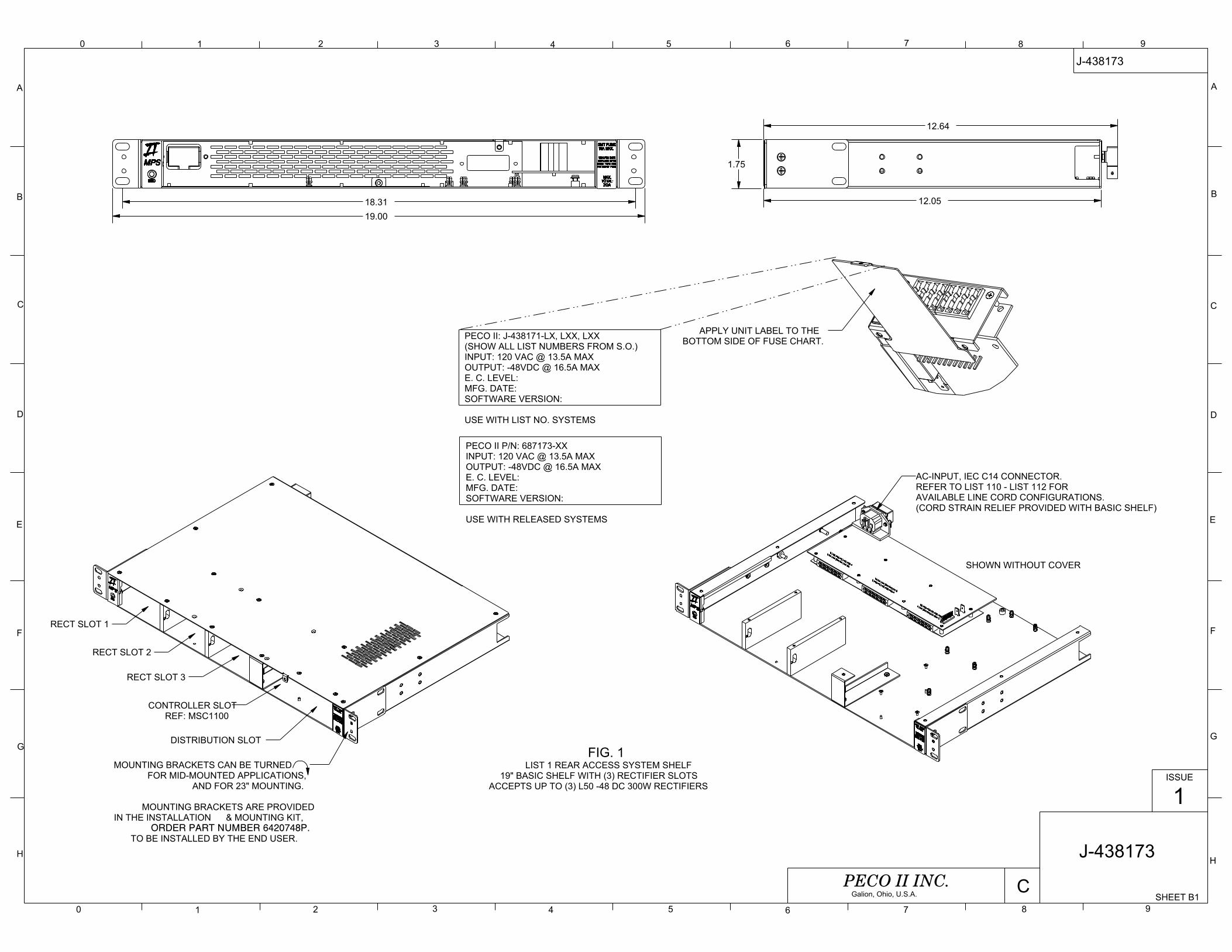
0 1 2 3 4 5 6 7 8 9
9876543210
A
B
C
D
E
F
G
H
A
B
C
D
E
F
G
H
12.05
19.0018.31
12.64
1.75
SHEET B1
J-438173
ISSUE
1
CPECO II INC.Galion, Ohio, U.S.A.
J-438173
FIG. 1LIST 1 REAR ACCESS SYSTEM SHELF
19" BASIC SHELF WITH (3) RECTIFIER SLOTSACCEPTS UP TO (3) L50 -48 DC 300W RECTIFIERS
PECO II: J-438171-LX, LXX, LXX(SHOW ALL LIST NUMBERS FROM S.O.)INPUT: 120 VAC @ 13.5A MAXOUTPUT: -48VDC @ 16.5A MAXE. C. LEVEL:MFG. DATE:SOFTWARE VERSION: USE WITH LIST NO. SYSTEMS
PECO II P/N: 687173-XXINPUT: 120 VAC @ 13.5A MAXOUTPUT: -48VDC @ 16.5A MAXE. C. LEVEL:MFG. DATE:SOFTWARE VERSION: USE WITH RELEASED SYSTEMS
RECT SLOT 1
RECT SLOT 2
RECT SLOT 3
CONTROLLER SLOTREF: MSC1100
DISTRIBUTION SLOT
MOUNTING BRACKETS CAN BE TURNED FOR MID-MOUNTED APPLICATIONS,
AND FOR 23" MOUNTING.
MOUNTING BRACKETS ARE PROVIDEDIN THE INSTALLATION & MOUNTING KIT,
ORDER PART NUMBER 6420748P.TO BE INSTALLED BY THE END USER.
SHOWN WITHOUT COVER
AC-INPUT, IEC C14 CONNECTOR.REFER TO LIST 110 - LIST 112 FORAVAILABLE LINE CORD CONFIGURATIONS.(CORD STRAIN RELIEF PROVIDED WITH BASIC SHELF)
APPLY UNIT LABEL TO THEBOTTOM SIDE OF FUSE CHART.

0 1 2 3 4 5 6 7 8 9
9876543210
A
B
C
D
E
F
G
H
A
B
C
D
E
F
G
H
SHEET B2
J-438173
ISSUE
1
CPECO II INC.Galion, Ohio, U.S.A.
J-438173
FIG. 2LIST 2 REAR ACCESS SYSTEM SHELF
19" BASIC SHELF WITH (2) RECTIFIER SLOTSACCEPTS UP TO (2) L51 -48 DC 2000W RECTIFIERS
SHOWN WITHOUT COVER
PECO II: J-438171-LX, LXX, LXX(SHOW ALL LIST NUMBERS FROM S.O.)INPUT: 120 VACOUTPUT: -48VDC @ 30A MAXE. C. LEVEL:MFG. DATE: USE WITH LIST NO. SYSTEMS
PECO II P/N: 687173-XXINPUT: 120 VACOUTPUT: -48VDC @ 30A MAXE. C. LEVEL:MFG. DATE: USE WITH RELEASED SYSTEMS
THIS PAGE LEFT BLANK
RECT SLOT 1
RECT SLOT 2
CONTROLLER SLOTREF: MSC1100
DISTRIBUTION SLOT

0 1 2 3 4 5 6 7 8 9
9876543210
A
B
C
D
E
F
G
H
A
B
C
D
E
F
G
H
SHEET B3
J-438173
ISSUE
1
CPECO II INC.Galion, Ohio, U.S.A.
J-438173
FIG. 20LIST 20 8 - POSITION GMT FUSE
DISTRIBUTION WITH 30A BATTERY DISCONNECT FUSE.16.5 AMPS TOTAL DISTRIBUTION.10 AMP MAX. FUSE PER POSITION
SHEET NOTE:PLUG-IN CONNECTORS ARE KEYED FOR EACH FUSED POSITION.(8) CONNECTORS ARE AVAILABLE SHIPPED LOOSE FOR INSTALLATIONBY THE END USER, REF. LIST 5, KIT- 6420748P.ADDITIONAL CONNECTORS ORDEREDSEPARATELY. REF. P/N: 3090125P-2K REFER TO SHEET C1 IF YOUR SYSTEMIS EQUIPPED WITH 8-POSITION CONNECTORS.
LIST 20 SHOWNINSTALLED IN LIST 1 BASIC SHELF
30A MAX. FUSETO BE INSTALLED BY THE END USER.FUSE ORDERED SEPARATELY, REF. L172P/N: 3150098P-30
LVLD BY-PASS JUMPERREMOVE AND REPLACE WITHLIST 70 LVLD MODULE, WHEN ORDERED.
-48V SUPPLY#8 SINGLE HOLE LUG
BOTTOM STUD: -48V RETURN OFFICE GROUND#8 SINGLE HOLE LUG
F1 LOAD & RETURN SHOWN.2-POS SCREW SPRING-CLAMP26-14 AWG WIRE SIZE(REF. P/N: 3090125P-2K)
TOP STUD: PRIMARY RETURNNOTE: MAKE THIS TERMINATION FIRST
WHEN INSTALLING. WHEN DISCONNECTING REMOVE THIS LEAD LAST.
FUSED LEAD RETURN LEAD
F2 LOAD & RETURN SHOWN.2-POS SCREW SPRING-CLAMP
26-14 AWG WIRE SIZE(REF. P/N: 3090125P-2K)
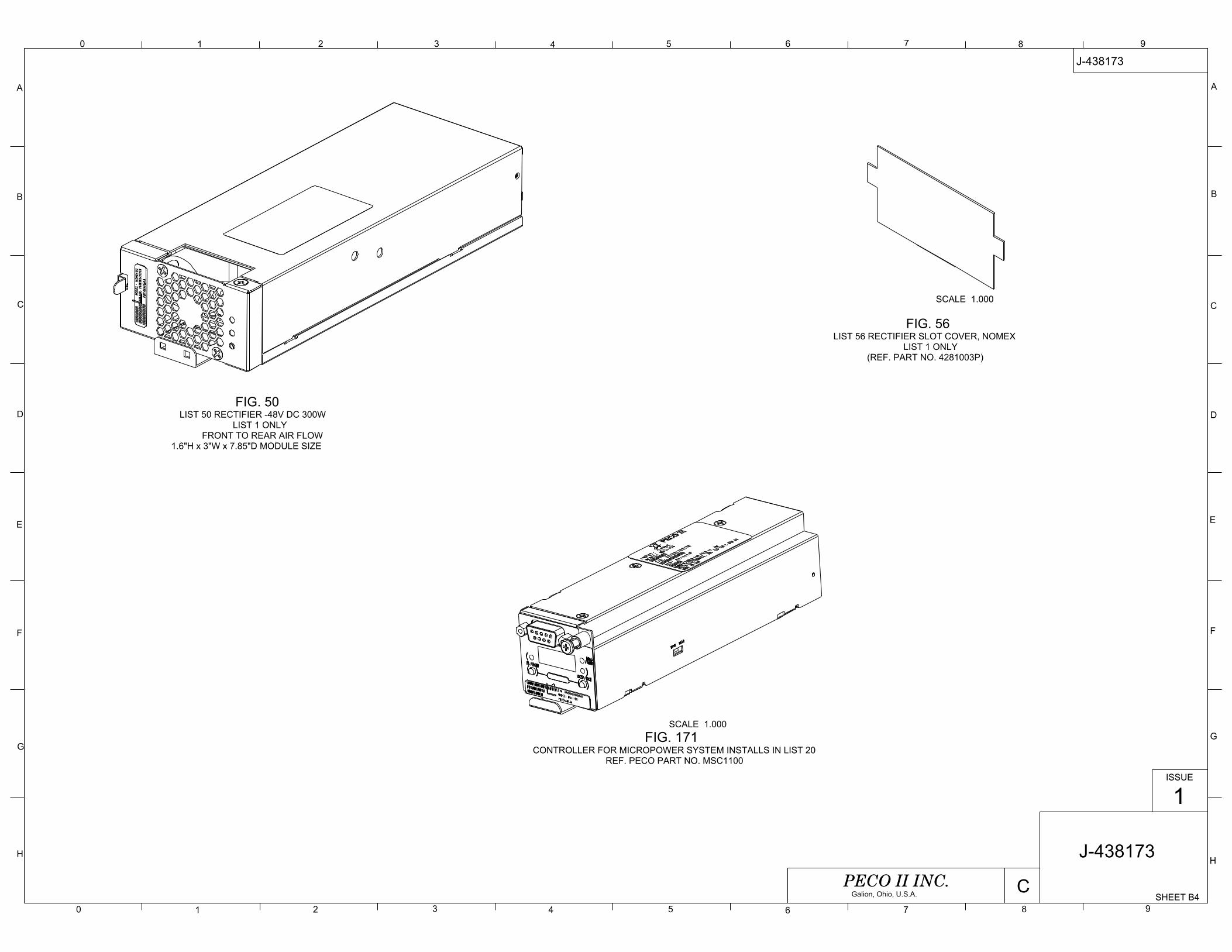
0 1 2 3 4 5 6 7 8 9
9876543210
A
B
C
D
E
F
G
H
A
B
C
D
E
F
G
H
SHEET B4
J-438173
ISSUE
1
CPECO II INC.Galion, Ohio, U.S.A.
J-438173
FIG. 50LIST 50 RECTIFIER -48V DC 300W
LIST 1 ONLYFRONT TO REAR AIR FLOW
1.6"H x 3"W x 7.85"D MODULE SIZE FIG. 51LIST 51 RECTIFIER -48V DC 2000W
LIST 20 ONLYFRONT TO REAR AIR FLOW
1.6"H x 4.95"W x 10.25"D MODULE SIZE
FIG. 56LIST 56 RECTIFIER SLOT COVER, NOMEX
LIST 1 ONLY(REF. PART NO. 4281003P)
FIG. 57LIST 57 RECTIFIER SLOT COVER, NOMEX
(REF. PART NO. 4281001P-3)FIG. 171
CONTROLLER FOR MICROPOWER SYSTEM INSTALLS IN LIST 20REF. PECO PART NO. MSC1100
SCALE 1.000
SCALE 1.000SCALE 1.000

0 1 2 3 4 5 6 7 8 9
9876543210
A
B
C
D
E
F
G
H
A
B
C
D
E
F
G
H
10 FT
10 FT.
SHEET B5
J-438173
ISSUE
1
CPECO II INC.Galion, Ohio, U.S.A.
J-438173
FIG. 70Low Voltage Load Disconnect (LVLD) MODULE
INSTALLS IN LIST 20REF. PECO PART NO. 438173-L70
FIG. 61LIST 61 TEMPERATURE PROBE EXTENSION CABLE, 10 FT
FOR USE WITH LIST 60. MULTIPLE CABLES CAN BE USED TOACHIEVE REQUIRED OVER ALL LENGTH.
REF. PECO PART NO. 6370523P
FIG. 60LIST 60 BATTERY TEMP PROBE
REF. PECO PART NO. 6370390P-5
1/4" HOLE IN RING LUG ALLOWS MOUNTING ON BATTERY POSTOR ON ANY OTHER SURFACE FOR VARIOUS TEMPERATURE READINGS
(RING LUG IS ELECTRICALLY ISOLATED)
SCALE 0.750
REMOVE BY-PASS JUMPERPLUG-IN LVLD MODULE
RE-INSTALL (2) SCREWS.

0 1 2 3 4 5 6 7 8 9
9876543210
A
B
C
D
E
F
G
H
A
B
C
D
E
F
G
H
SHEET B6
J-438173
ISSUE
1
CPECO II INC.Galion, Ohio, U.S.A.
J-438171
1
18
K1NO COM NC
K2NO COM NC
K3NO COM NC
NO COM NCK4
NO COM NCK5
NO COM NCK6
SHEET NOTE - * LIST 90 & LIST 91ARE SHOWN WITH TEMPERATURE PROBE LOOP-BACK JUMPER INSTALLED.LOOP-BACK JUMPER IS PROVIDED WITH EACH SHELF, AND IS REQUIREDFOR OPERATION, WHEN A TEMPERATURE PROBE IS NOT USED.REF. PECO PART NO. 6370521P
FIG. 90 ALARM OUTPUT WITH SNMP & TEMPREF. PECO PART NO. 438173-L90
INSTALLS IN LIST 20
TEMPERATURE PROBE EXTENSION CONNECTION.
REF. LIST 61, OR LIST 62* SEE SHEET NOTE.
RJ45 CONNECTIONFOR ALARMS WITH SNMP.
FIG. 91ALARM OUTPUT DRY CONTACTS & TEMP
REF. PECO PART NO. 438173-L91INSTALLS IN LIST 20
TEMPERATURE PROBE EXTENSION CONNECTION.
REF. LIST 61, OR LIST 62* SEE SHEET NOTE.
REF. PECO PART NO. 6370521P
ALARM CABLE CONNECTION.REF. LIST 95, OR LIST 96.
FIG. 95LIST 95 ALARM CABLE 10 FT FOR LIST 91 LIST 96 ALARM CABLE 50 FT FOR LIST 91
REF. PECO PART NO. 6370517P-10 AND 6370517P-50
438173-L90 SHOWNINSTALLED IN POWER SHELF.(LABEL IS APPLIED TO COVER)
TEMP PROBE LOOP-BACK JUMPER, REQUIRED WHEN TEMP PROBE IS NOT INSTALLED.
* SEE SHEET NOTE.REF. PECO PART NO. 6370521P
438173-L91 SHOWNINSTALLED IN POWER SHELF.(LABEL IS APPLIED TO COVER)
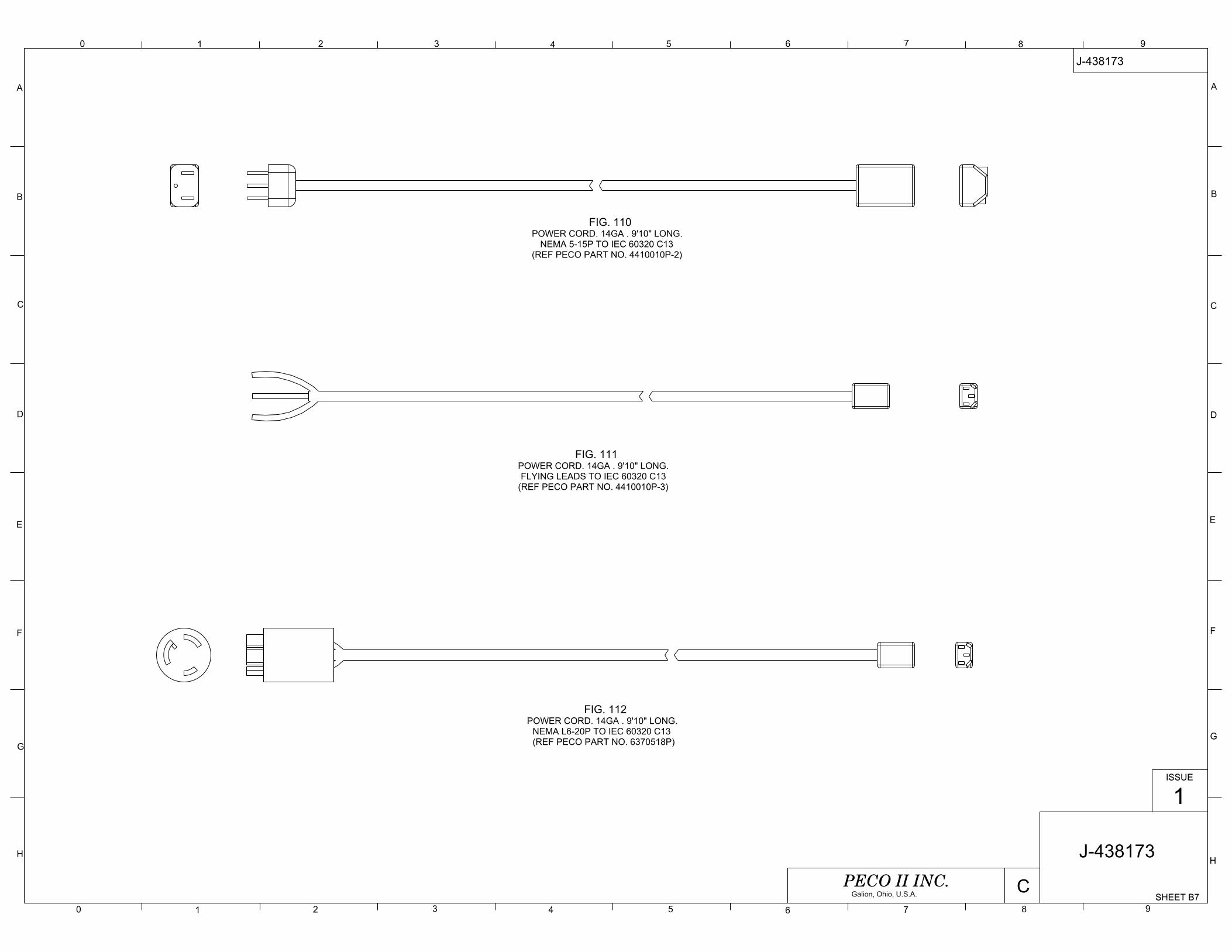
0 1 2 3 4 5 6 7 8 9
9876543210
A
B
C
D
E
F
G
H
A
B
C
D
E
F
G
H
SHEET B7
J-438173
ISSUE
1
CPECO II INC.Galion, Ohio, U.S.A.
J-438173
FIG. 110POWER CORD. 14GA . 9'10" LONG.
NEMA 5-15P TO IEC 60320 C13(REF PECO PART NO. 4410010P-2)
FIG. 111POWER CORD. 14GA . 9'10" LONG.FLYING LEADS TO IEC 60320 C13
(REF PECO PART NO. 4410010P-3)
FIG. 112POWER CORD. 14GA . 9'10" LONG.
NEMA L6-20P TO IEC 60320 C13(REF PECO PART NO. 6370518P)

0 1 2 3 4 5 6 7 8 9
9876543210
A
B
C
D
E
F
G
H
A
B
C
D
E
F
G
H
SHEET B8
J-438173
ISSUE
1
CPECO II INC.Galion, Ohio, U.S.A.
J-438173SHEET NOTES:1. THIS SHEET MAY HAVE COMMON HARDWARE REMOVED FOR CLARITY.
FIG. 1406270068P 23" RELAY RACK
7'-0" TALL WITH 5" REINFORCED SIDE RAILSCONTAINS (45) 1.75" NEMA RACK UNIT SPACES FIG. 141
6270068P-1 23" RELAY RACK42" TALL WITH 5" SIDE RAILS
CONTAINS (21) 1.75" NEMA RACK UNIT SPACES
FOOTPRINT FOR BOTH RELAY RACK FRAMESSYMMETRICAL FRONT TO BACK AND LEFT TO RIGHT
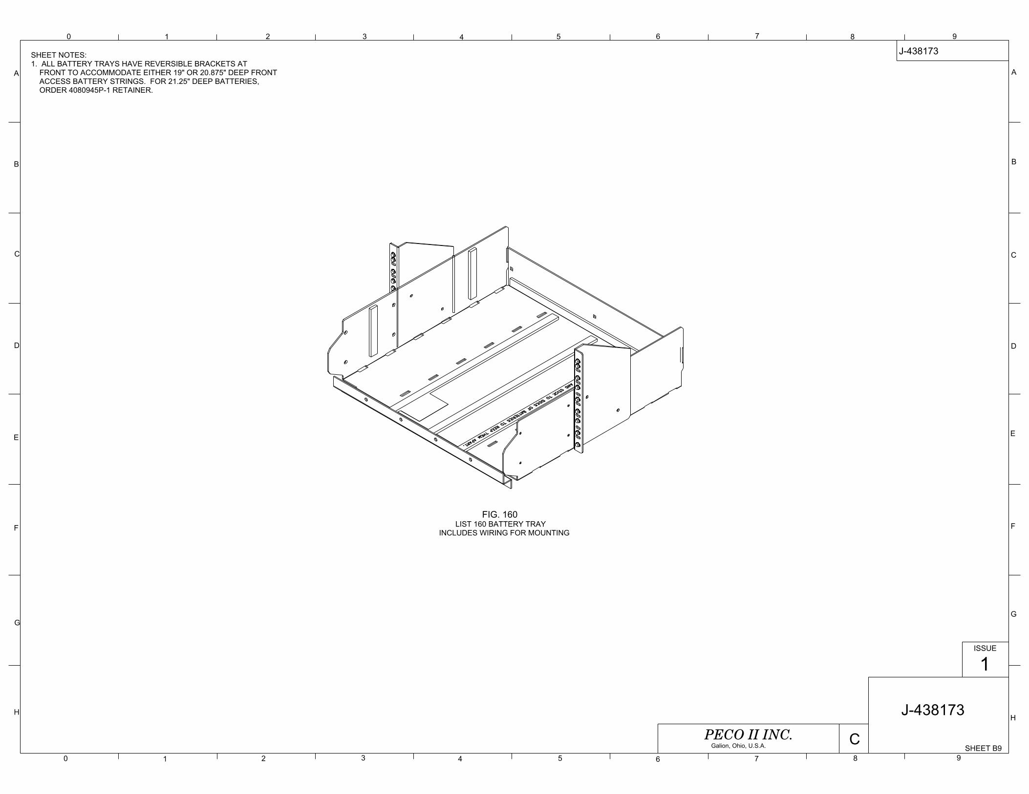
0 1 2 3 4 5 6 7 8 9
9876543210
A
B
C
D
E
F
G
H
A
B
C
D
E
F
G
H
SHEET B9
J-438173
ISSUE
1
CPECO II INC.Galion, Ohio, U.S.A.
J-438173
FIG. 160LIST 160 BATTERY TRAY
INCLUDES WIRING FOR MOUNTING
SHEET NOTES:1. ALL BATTERY TRAYS HAVE REVERSIBLE BRACKETS AT FRONT TO ACCOMMODATE EITHER 19" OR 20.875" DEEP FRONT ACCESS BATTERY STRINGS. FOR 21.25" DEEP BATTERIES, ORDER 4080945P-1 RETAINER.

0 1 2 3 4 5 6 7 8 9
9876543210
A
B
C
D
E
F
G
H
A
B
C
D
E
F
G
H
SHEET C1
J-438173
ISSUE
1
CPECO II INC.Galion, Ohio, U.S.A.
J-438173
FIG. 20LIST 20 8 - POSITION GMT FUSE
DISTRIBUTION WITH 30A BATTERY DISCONNECT FUSE.16.5 AMPS TOTAL DISTRIBUTION.10 AMP MAX. FUSE PER POSITION
SHEET NOTE:EARLY PRODUCTION SYSTEMS ARE EQUIPPED WITH (2) 8-POSITIONSINGLE-ROW CONNECTORS FOR LOAD AND RETURN TERMINATIONS AS SHOWN ON THIS SHEET. ALL LOAD TERMINATION ARE MADE TO THE TOP CONNECTOR,ALL RETURNS ARE MADE TO THE BOTTOM CONNECTOR. THE (2) PLUG-IN CONNECTORS ARE KEYED FOR LOAD / RETURN,AND ARE PROVIDED SHIPPED LOOSE FOR INSTALLATION BY THE END USER. ADDITIONAL CONNECTORS ORDERED SEPARATELY. REF. P/N's: 3090592P-8 FOR LOADS3090593P-8 FOR RETURNS
LIST 20 SHOWNINSTALLED IN LIST 1 BASIC SHELF
30A MAX. FUSETO BE INSTALLED BY THE END USER.FUSE ORDERED SEPARATELY, REF. L172P/N: 3150098P-30
LVLD BY-PASS JUMPERREMOVE AND REPLACE WITHLIST 70 LVLD MODULE, WHEN ORDERED.
-48V SUPPLY#8 SINGLE HOLE LUG
BOTTOM STUD: -48V RETURN OFFICE GROUND#8 SINGLE HOLE LUG
TOP STUD: PRIMARY RETURNNOTE: MAKE THIS TERMINATION FIRST
WHEN INSTALLING. WHEN DISCONNECTING REMOVE THIS LEAD LAST.
-48V LOADS (8-CIRCUITS)SCREW SPRING-CLAMP26-14 AWG WIRE SIZE(REF. P/N: 3090592P-8)
RETURNS (8-CIRCUITS)SCREW SPRING-CLAMP26-14 AWG WIRE SIZE(REF. P/N: 3090593P-8)
F1F8
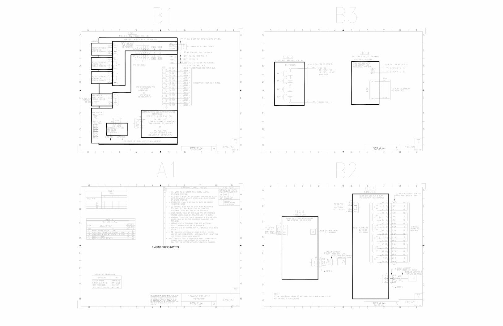
ENGINEERING NOTES:
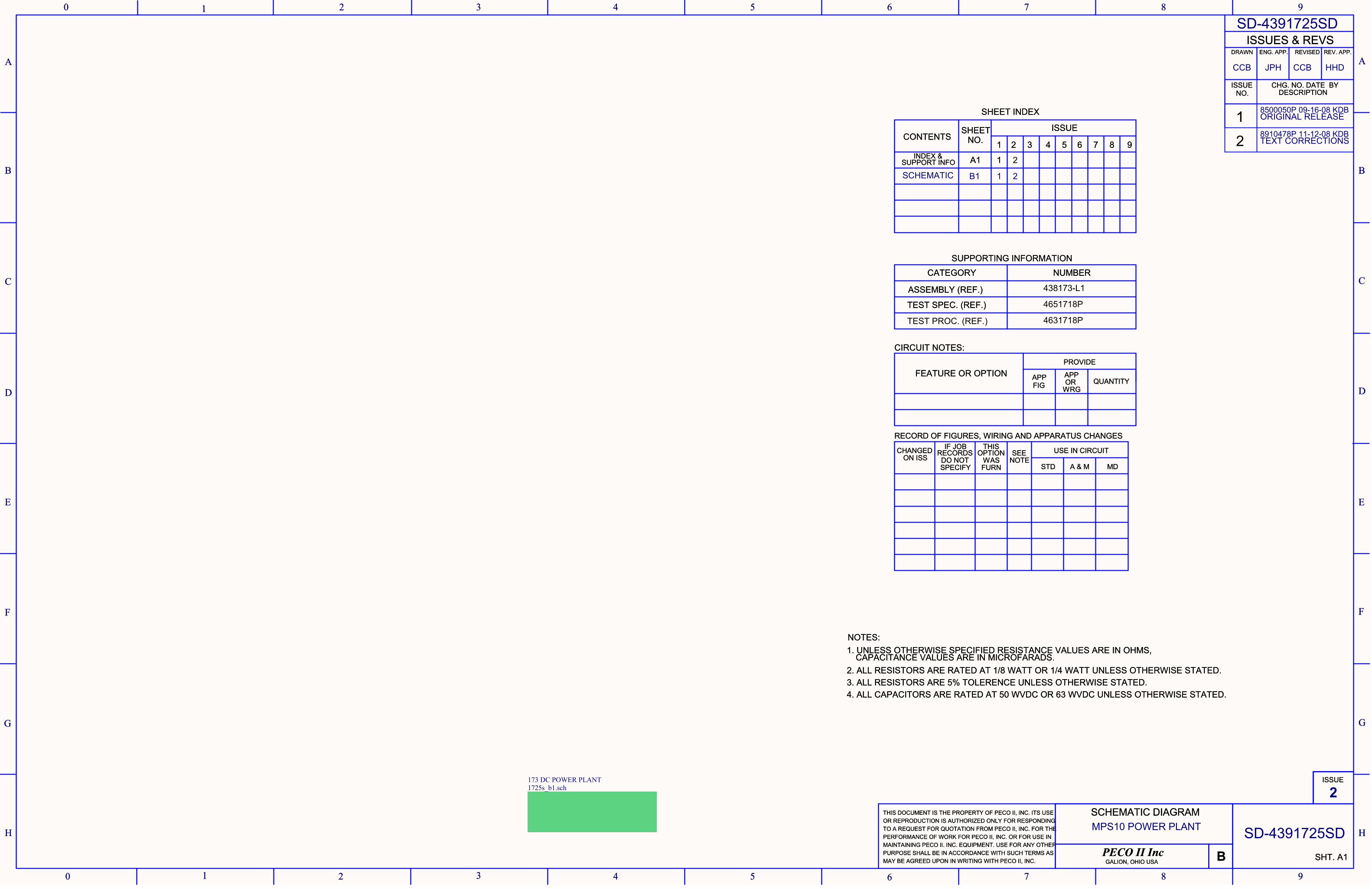
PECO II IncGALION, OHIO USA SHT. A1
ISSUE
B
THIS DOCUMENT IS THE PROPERTY OF PECO II, INC. ITS USEOR REPRODUCTION IS AUTHORIZED ONLY FOR RESPONDINGTO A REQUEST FOR QUOTATION FROM PECO II, INC. FOR THEPERFORMANCE OF WORK FOR PECO II, INC. OR FOR USE INMAINTAINING PECO II. INC. EQUIPMENT. USE FOR ANY OTHERPURPOSE SHALL BE IN ACCORDANCE WITH SUCH TERMS ASMAY BE AGREED UPON IN WRITING WITH PECO II, INC.
0 1 2 3 4 5 6 7 8 9
A
B
C
D
E
F
G
H
9876543210
H
G
F
E
D
C
B
A
1. UNLESS OTHERWISE SPECIFIED RESISTANCE VALUES ARE IN OHMS,CAPACITANCE VALUES ARE IN MICROFARADS.
2. ALL RESISTORS ARE RATED AT 1/8 WATT OR 1/4 WATT UNLESS OTHERWISE STATED.3. ALL RESISTORS ARE 5% TOLERENCE UNLESS OTHERWISE STATED.4. ALL CAPACITORS ARE RATED AT 50 WVDC OR 63 WVDC UNLESS OTHERWISE STATED.
NOTES:
SHEET INDEX
ISSUESHEETNO.CONTENTS
1 2 3 4 5 6 7 8 9
SUPPORTING INFORMATION
ASSEMBLY (REF.)
TEST SPEC. (REF.)
CIRCUIT NOTES:PROVIDE
FEATURE OR OPTION APP APPFIG OR
WRGQUANTITY
RECORD OF FIGURES, WIRING AND APPARATUS CHANGES
CHANGEDON ISS
IF JOBRECORDS
DO NOTSPECIFY
THISOPTION
WASFURN
SEENOTE
USE IN CIRCUIT
STD A & M MD
CATEGORY NUMBER
INDEX &SUPPORT INFO A1 1
ISSUES & REVSDRAWN ENG. APP. REVISED REV. APP.
ISSUENO.
CHG. NO. DATE BYDESCRIPTION
1
SCHEMATIC DIAGRAM
CCB JPH
8500050P 09-16-08 KDBORIGINAL RELEASE
B1 1SCHEMATIC
MPS10 POWER PLANT SD-4391725SD
SD-4391725SD
2173 DC POWER PLANT1725s_b1.sch
TEST PROC. (REF.)
2
2
CCB HHD
2 8910478P 11-12-08 KDBTEXT CORRECTIONS
4651718P
4631718P
438173-L1
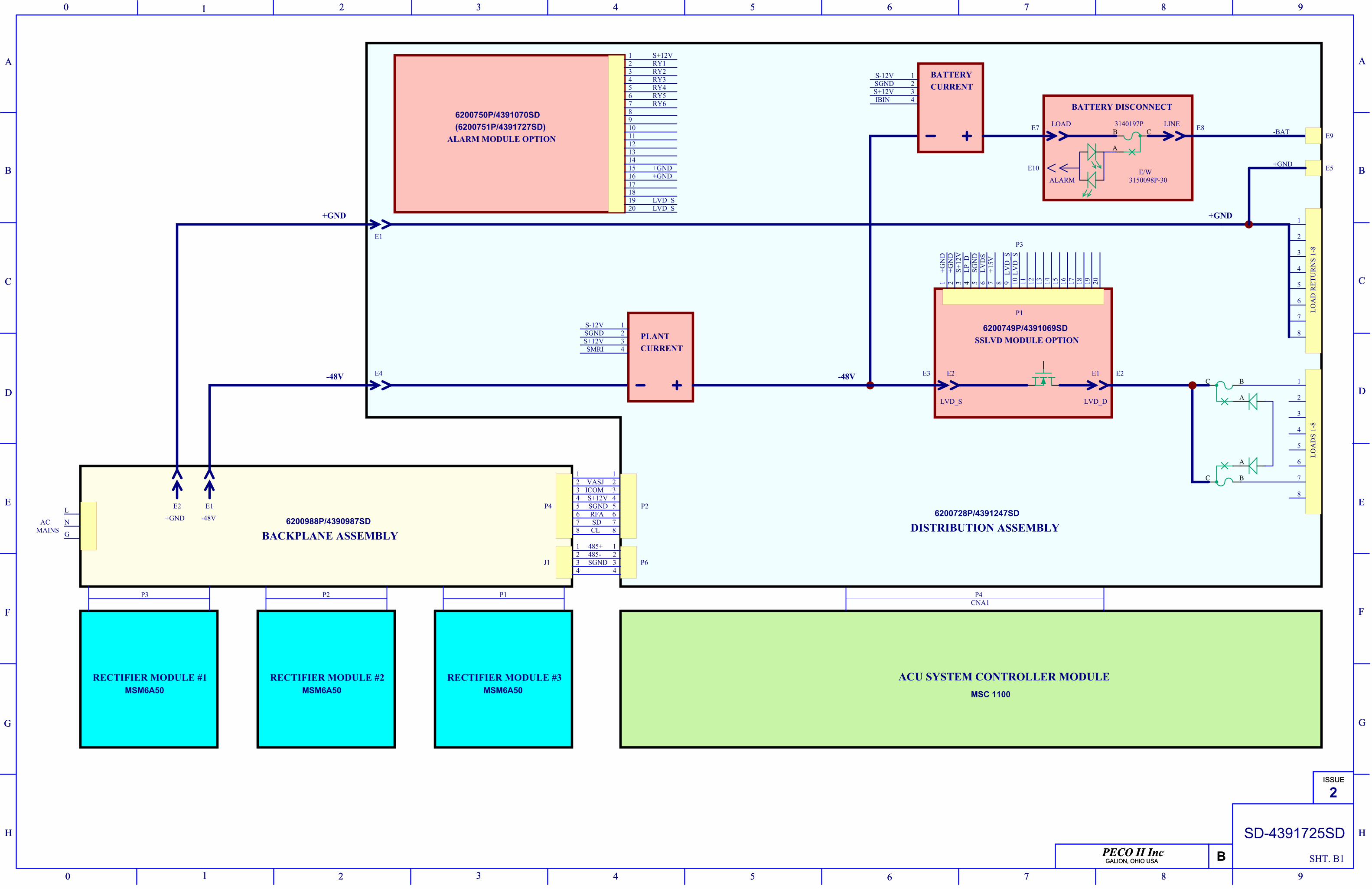
PECO II IncGALION, OHIO USA
ISSUE
B
0 1 2 3 4 5 6 7 8 9
A
B
C
D
E
F
G
H
9876543210
H
G
F
E
D
C
B
A
PECO II IncGALION, OHIO USA
ISSUE
B
0 1 2 3 4 5 6 7 8 9
A
B
C
D
E
F
G
H
9876543210
H
G
F
E
D
C
B
A
SD-4391725SD
2
SHT. B1
RECTIFIER MODULE #1
+GND -48V
P3 P2
BACKPLANE ASSEMBLY
P4CNA1
ACU SYSTEM CONTROLLER MODULE
MAINS
L
G
N 6200988P/4390987SD
1234
E2 E1 P4
P1
5678
12345678
RECTIFIER MODULE #2 RECTIFIER MODULE #3
-BAT
+GND
1
2
3
4
5
6
7
1
2
3
4
5
6
7
AC
BC
A
BC
A
-48V
+GND
B C
A
BATTERY DISCONNECT
SSLVD MODULE OPTION
ALARM MODULE OPTION
DISTRIBUTION ASSEMBLY
123456789101112
P2
+GND
-48V
BATTERYCURRENT
PLANTCURRENT
1 2 3 4
P1
5 6 7 8
LOA
DS
1-8
LOA
D R
ETU
RN
S 1-
8
S+12VRY1RY2RY3RY4RY5RY6
+GN
D+G
ND
LP_D
S+12
V
LVD
S+1
5V
SGN
D
S-12VSGNDS+12VSMRI
1234
S-12VSGNDS+12VIBIN
1234
VASJICOMS+12VSGNDRFA
CLSD
8
8
E1
E4
LOAD LINE
E2 E1
LVD_S LVD_D
E9
E514151617181920
+GND
LVD_SLVD_S
13
9 10 11 12 13 14 15 16 17 18 19 20
LVD
_SLV
D_S
+GND
6200750P/4391070SD
6200749P/4391069SD
6200728P/4391247SD
MSC 1100MSM6A50 MSM6A50 MSM6A50
ALARM
3140197P
E/W3150098P-30
P3
E3 E2
E7
E10
E8(6200751P/4391727SD)
1234
1234
485+485-SGNDJ1 P6
P0D?0A P0D?0K
P0D?0A P0D?0K
P0D?0A P0D?0K
P0D?0A P0D?0K
P0F?0A
P0F?0B
P0F?0C
P0F?0A P0F?0B
P0F?0C
P0F?0A
P0F?0B P0F?0C
P0Q?0D
P0Q?0G
P0Q?0S
P0D?0A P0D?0K P0F?0A
P0F?0A
P0F?0B
P0F?0C P0Q?0D
P0Q?0G
P0Q?0S
Top Related