


Languages
Pages
Legal

From high-rigidity hydraulic clamp units to a wide variety of From high-rigidity hydraulic clamp units to a wide variety of compact clamp units, HY CLAMP LIGHT, compact clamp units, HY CLAMP LIGHT, for jig-related equipment.for jig-related equipment.
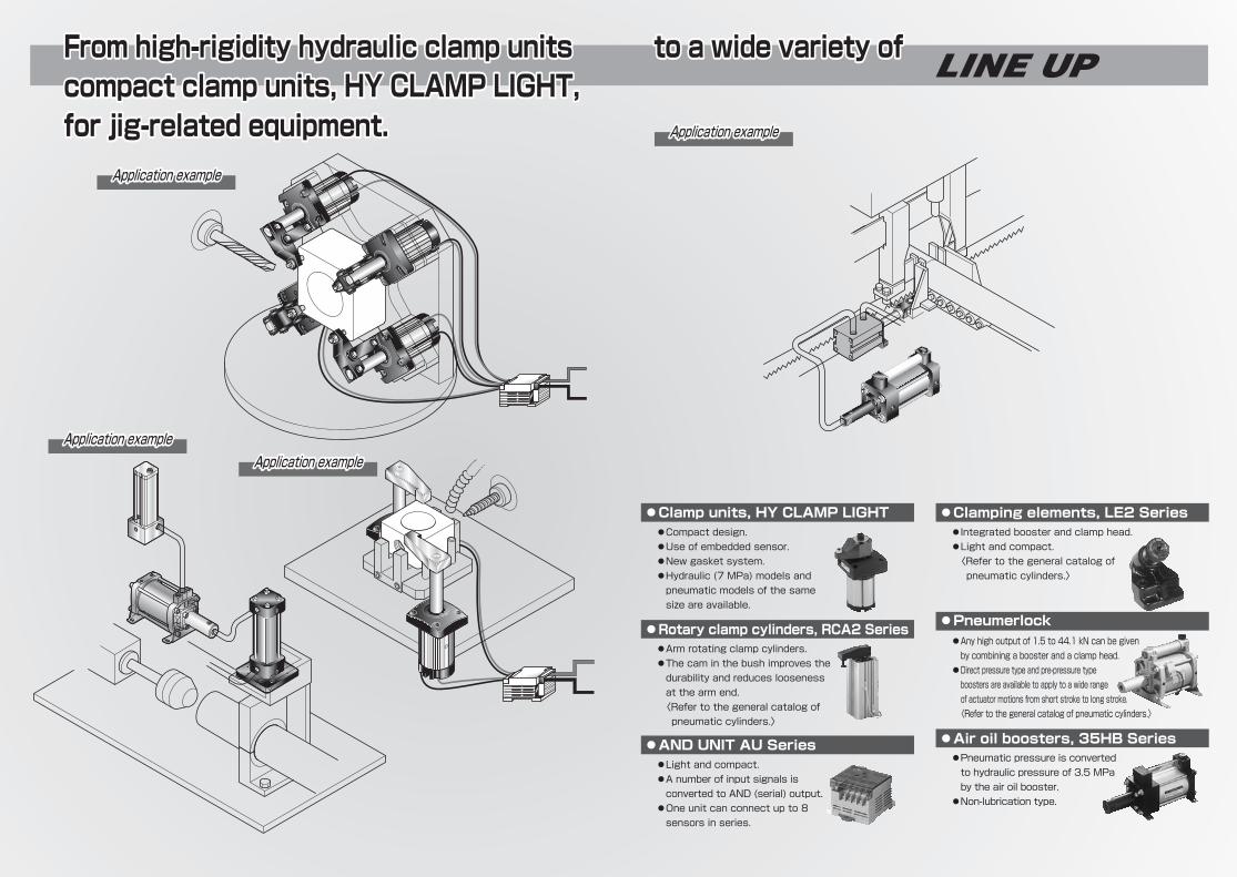
●Any high output of 1.5 to 44.1 kN can be given by combining a booster and a clamp head.
●Direct pressure type and pre-pressure type boosters are available to apply to a wide range of actuator motions from short stroke to long stroke.〈Refer to the general catalog of pneumatic cylinders.〉
●Pneumatic pressure is converted to hydraulic pressure of 3.5 MPa by the air oil booster.
●Non-lubrication type.
●Light and compact.●A number of input signals is converted to AND (serial) output.
●One unit can connect up to 8 sensors in series.
●Arm rotating clamp cylinders.●The cam in the bush improves the durability and reduces looseness at the arm end.〈Refer to the general catalog of pneumatic cylinders.〉
●Compact design.●Use of embedded sensor.●New gasket system.●Hydraulic (7 MPa) models and pneumatic models of the same size are available.
●Integrated booster and clamp head.●Light and compact.〈Refer to the general catalog of pneumatic cylinders.〉
LINE UP
●Clamp units, HY CLAMP LIGHT
●Rotary clamp cylinders, RCA2 Series
●Clamping elements, LE2 Series
●Pneumerlock
●Air oil boosters, 35HB Series●AND UNIT AU Series
From high-rigidity hydraulic clamp units to a wide variety of compact clamp units, HY CLAMP LIGHT, for jig-related equipment.
Application exampleApplication exampleApplication example
Application exampleApplication exampleApplication example
Application exampleApplication exampleApplication example
Application exampleApplication exampleApplication example

JEH/JEAJEH/JEA Clamp Units
4HK
JEH/JEAClamp Units
JEH/JEA
5HK
Series
JEHS(swing type)
JEHM(move with
turning type)
JEHP(move afterturning type)
JEHF(front mount)
JEHR(rear mount)
JEHF-U(side support)
JEAS(swing type)
JEHM(move with
turning type)
Mounting style Piping port positionRod end type
Hyd
raul
ic m
odel
sP
neum
atic
mod
els
Front mount
Male thread type
Male thread type
Male thread type
H
H
H
HR
To select a clamp unit, it is necessary to determine the following items.■Clamp operation typeFor unclamping, the clamp arm must be evacuated or have a special form depending on the shape of the jig or work. Determine the type in consideration of this.■Selection of clamp unit boreSelect the bore in accordance with the following procedures.①To apply the cylinder force directly on the clamp unit axis centerIn this case, select the bore referring to the cylinder force table. Examine the bore on the assumption that the cylinder output (actual output of the piston rod) is 95% of the cylinder force.
②To apply the cylinder force at a distance from the clamp unit axis centerIn this case, the clamp force varies depending on the length of the clamp arm to be used. Determine the bore from the clamp force diagram.
■Stroke Select the stroke in consideration of the clamping distance, evacuating distance and clamp structure.■Shape of piston rod There are pin type and male thread type rod ends. Select the shape appropriate to the clamp arm mounting method.Shapes of piston rod end
■Position of piping port The piping port is positioned on the rod or cap side (side H). There are threaded type and gasket type ports. Select the position in consideration of the jig shape, work shape, and disposal of cuttings.■Selection of piping port position
φ32
φ40
φ50
φ63
φ20
φ25
φ32
φ40
Extension side
Retraction side
Extension side
Retraction side
Extension side
Retraction side
Extension side
Retraction side
804
490
1257
766
1963
1159
3117
1860
0.40
0.25
0.63
0.38
0.98
0.58
1.56
0.93
0.80
0.49
1.26
0.77
1.96
1.16
3.12
1.86
1.61
0.98
2.51
1.53
3.93
2.32
6.23
3.72
2.41
1.47
3.77
2.30
5.89
3.48
9.35
5.58
3.22
1.96
5.03
3.06
7.85
4.64
12.47
7.44
4.02
2.45
6.29
3.83
9.82
5.80
15.59
9.30
4.82
2.94
7.54
4.60
11.78
6.95
18.70
11.16
5.63
3.43
8.80
5.36
13.74
8.11
21.82
13.02
2.0 3.0 4.0 5.0 6.0 7.00.5 1.0
Cylinder Force Table
Boremm
Rod dia.mm
Pressurereceiving area
mm2
Workingdirection
Hydraulic (pneumatic) pressure MPa
Unit: kN
■Clamp unit output table
Female threaded port on rod side Female threaded port on cap sideGasket type port on rod side
Pin type Male thread type
Product Confi guration Factors for Selection of Clamp Unit
JEH/JEAJEH/JEA Clamp Units
6HK
JEH/JEAClamp Units
JEH/JEA
7HK
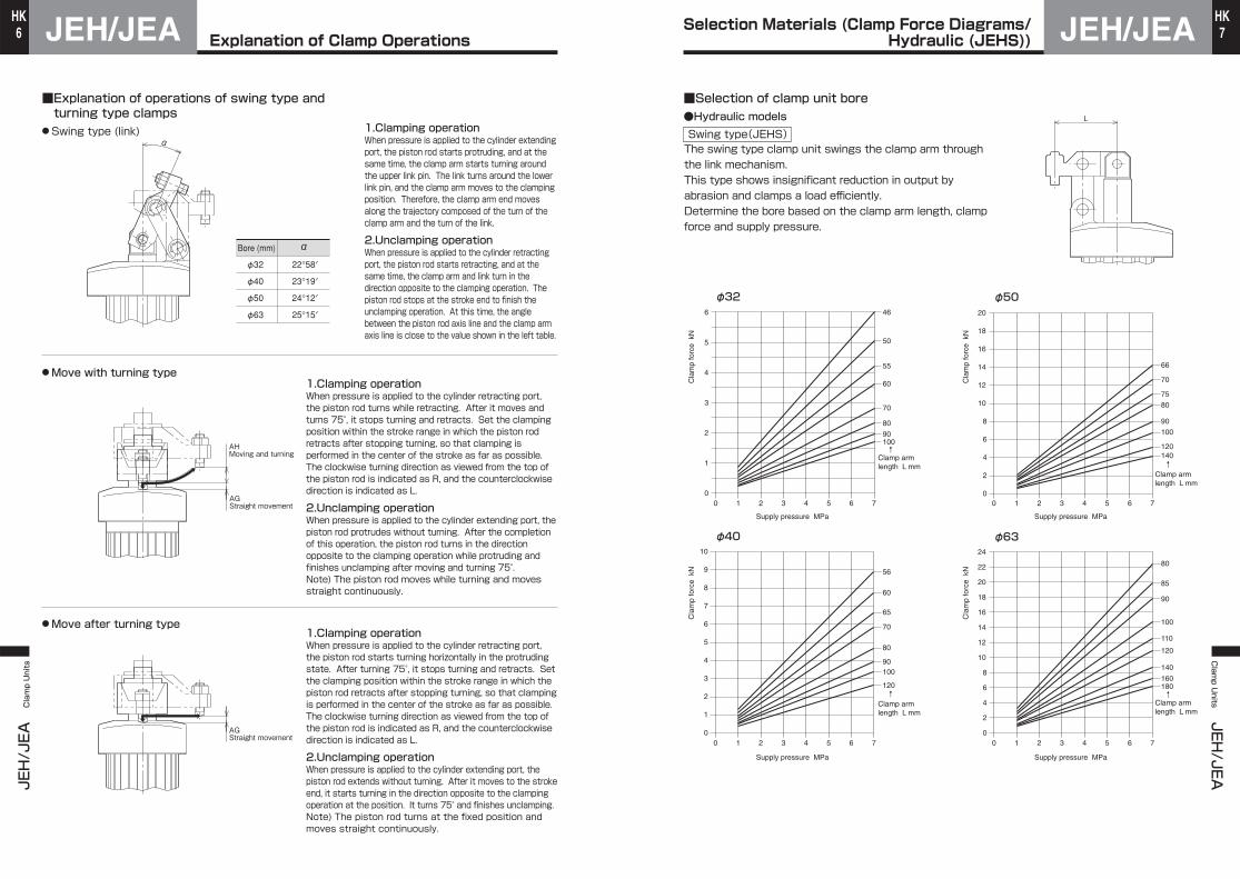
■Explanation of operations of swing type and turning type clamps
●Swing type (link) 1.Clamping operationWhen pressure is applied to the cylinder extending port, the piston rod starts protruding, and at the same time, the clamp arm starts turning around the upper link pin. The link turns around the lower link pin, and the clamp arm moves to the clamping position. Therefore, the clamp arm end moves along the trajectory composed of the turn of the clamp arm and the turn of the link.
2.Unclamping operationWhen pressure is applied to the cylinder retracting port, the piston rod starts retracting, and at the same time, the clamp arm and link turn in the direction opposite to the clamping operation. The piston rod stops at the stroke end to finish the unclamping operation. At this time, the angle between the piston rod axis line and the clamp arm axis line is close to the value shown in the left table.
●Move with turning type
●Move after turning type
1.Clamping operationWhen pressure is applied to the cylinder retracting port, the piston rod turns while retracting. After it moves and turns 75°, it stops turning and retracts. Set the clamping position within the stroke range in which the piston rod retracts after stopping turning, so that clamping is performed in the center of the stroke as far as possible.The clockwise turning direction as viewed from the top of the piston rod is indicated as R, and the counterclockwise direction is indicated as L.
2.Unclamping operationWhen pressure is applied to the cylinder extending port, the piston rod protrudes without turning. After the completion of this operation, the piston rod turns in the direction opposite to the clamping operation while protruding and finishes unclamping after moving and turning 75°.Note) The piston rod moves while turning and moves straight continuously.
1.Clamping operationWhen pressure is applied to the cylinder retracting port, the piston rod starts turning horizontally in the protruding state. After turning 75°, it stops turning and retracts. Set the clamping position within the stroke range in which the piston rod retracts after stopping turning, so that clamping is performed in the center of the stroke as far as possible.The clockwise turning direction as viewed from the top of the piston rod is indicated as R, and the counterclockwise direction is indicated as L.
2.Unclamping operationWhen pressure is applied to the cylinder extending port, the piston rod extends without turning. After it moves to the stroke end, it starts turning in the direction opposite to the clamping operation at the position. It turns 75° and finishes unclamping.Note) The piston rod turns at the fixed position and moves straight continuously.
φ32
φ40
φ50
φ63
Bore (mm) α
22°58′
23°19′
24°12′
25°15′
α
AHMoving and turning
AGStraight movement
AGStraight movement
■Selection of clamp unit bore●Hydraulic models Swing type(JEHS)The swing type clamp unit swings the clamp arm through the link mechanism.This type shows insignificant reduction in output by abrasion and clamps a load efficiently.Determine the bore based on the clamp arm length, clamp force and supply pressure.
L
Cla
mp
forc
e k
N
Cla
mp
forc
e k
N
Cla
mp
forc
e k
N
Cla
mp
forc
e k
N
Supply pressure MPa
Supply pressure MPa
Supply pressure MPa
Supply pressure MPa
Clamp arm length L mm
Clamp arm length L mm
10090
80
70
60
55
50
466
Clamp arm length L mm
Clamp arm length L mm
120
10090
80
70
65
60
569
7
5
3
1
φ40
φ32
10 2 3 4 5 6 70
2
4
6
8
10
5
4
3
2
1
076543210
180160
110
140
120
100
90
85
8022
24
140120
100
90
80
75
70
18
14
10
6
2
66
18
14
10
6
2
φ63
φ50
10 2 3 4 5 6 70
4
8
12
16
20
20
16
12
8
4
076543210
↑
↑ ↑
↑
Explanation of Clamp OperationsSelection Materials (Clamp Force Diagrams/
Hydraulic (JEHS))

JEH/JEAJEH/JEA Clamp Units
8HK
JEH/JEAClamp Units
JEH/JEA
9HK
■Selection of clamp unit bore●Hydraulic models● Turning typeWhen the turning type clamp unit clamps a load, bending moment is applied to the piston rod. As the clamp arm becomes longer, the bending moment applied to the piston rod increases. Therefore, the working pressure range is limited according to the arm length. Determine the bore, arm length and set pressure within the allowable range of use referring to the clamp force diagram and limit working pressure diagram.(When using optional parts, select proper ones in the same manner.)
Move with turning type(JEHM) Move after turning type(JEHP)
L
Clamp arm length L mm
Clamp arm length L mm
Clamp arm length L mm
Clamp arm length L mm
140120
100
8090
71
90
140
10080
160
120
7060
160
10
9
8
7
6
10 2 3 4 5 6 70
5
4
3
2
1
φ50,φ63
80 90100
7060
5246
1201101009080706053
5
4.5
4
3.5
3
2.5
2
1.5
1
0.5
φ32,φ40
076543210
φ63
140
120
100
8090
71
90
140
10080
160
120
7060
10
9
8
7
6
10 2 3 4 5 6 70
5
4
3
2
1
φ50,φ63
80 90100
7060
52461101009080706053
5
4.5
4
3.5
3
2.5
2
1.5
1
0.5
φ32,φ40
076543210
φφ4040
φφ3232
φ40
φ32
φφ5050φ50φφ5050
φφ6363
φ50
φ63
φφ3232
φφ4040 Unallowable
Unallowable
range of use
range of use
Unallowable
range of use
φ32
φ40
Cla
mp
forc
e k
N
Cla
mp
forc
e k
N
Cla
mp
forc
e k
N
Cla
mp
forc
e k
N
Supply pressure MPaSupply pressure MPa
Supply pressure MPa Supply pressure MPa
Unallowable
Unallowable
range of use
range of use
Unallowable
range of use
Unallowable
Unallowable
range of use
range of useUnallowable
range of use
Unallowable
Unallowable
range of use
range of use
Unallowable
range of use
Unallowable
Unallowable
range of use
range of useUnallowable
range of use
Unallowable
Unallowable
range of use
range of useUnallowable
range of use
Unallowable
Unallowable
range of use
range of use
Unallowable
range of use
Unallowable
Unallowable
range of use
range of useUnallowable
range of use
■Selection of clamp unit bore●Pneumatic models Swing type(JEAS)The swing type clamp unit swings the clamp arm through the link mechanism.This type shows insignificant reduction in output by abrasion and clamps a load efficiently.Determine the bore based on the clamp arm length, clamp force and supply pressure.
L
1.1
0.8
0.7
0.8
90
80
70
60
55
50
46
0.6
10090
80
70
65
60
56
0.9
0.7
0.5
0.3
0.1
φ40
φ32
0.10 0.2 0.3 0.4 0.5 0.6 0.70
0.2
0.4
0.6
0.8
1.0
0.5
0.4
0.3
0.2
0.1
00.70.60.50.40.30.20.10
0.8
2.6
0.8
160
110
140
120
100
90
85
80
2.2
2.4
120
100
90
80
75
70
1.8
1.4
1.0
0.6
0.2
66
1.8
1.4
1.0
0.6
0.2
φ63
φ50
0.10 0.2 0.3 0.4 0.5 0.6 0.70
0.4
0.8
1.2
1.6
2.0
2.0
1.6
1.2
0.8
0.4
00.70.60.50.40.30.20.10
Clamp arm length L mm
Clamp arm length L mm
Clamp arm length L mm
Clamp arm length L mm
Cla
mp
forc
e k
N
Cla
mp
forc
e k
N
Cla
mp
forc
e k
N
Cla
mp
forc
e k
N
Supply pressure MPa Supply pressure MPa
Supply pressure MPa Supply pressure MPa
100
120 180
140↑
↑ ↑
↑
Selection Materials (Clamp force diagrams/Hydraulic (JEHM/JEHP))
Selection Materials (Clamp Force Diagrams/Pneumatic (JEAS))
JEH/JEAJEH/JEA Clamp Units
10HK
JEH/JEAClamp Units
JEH/JEA
11HK
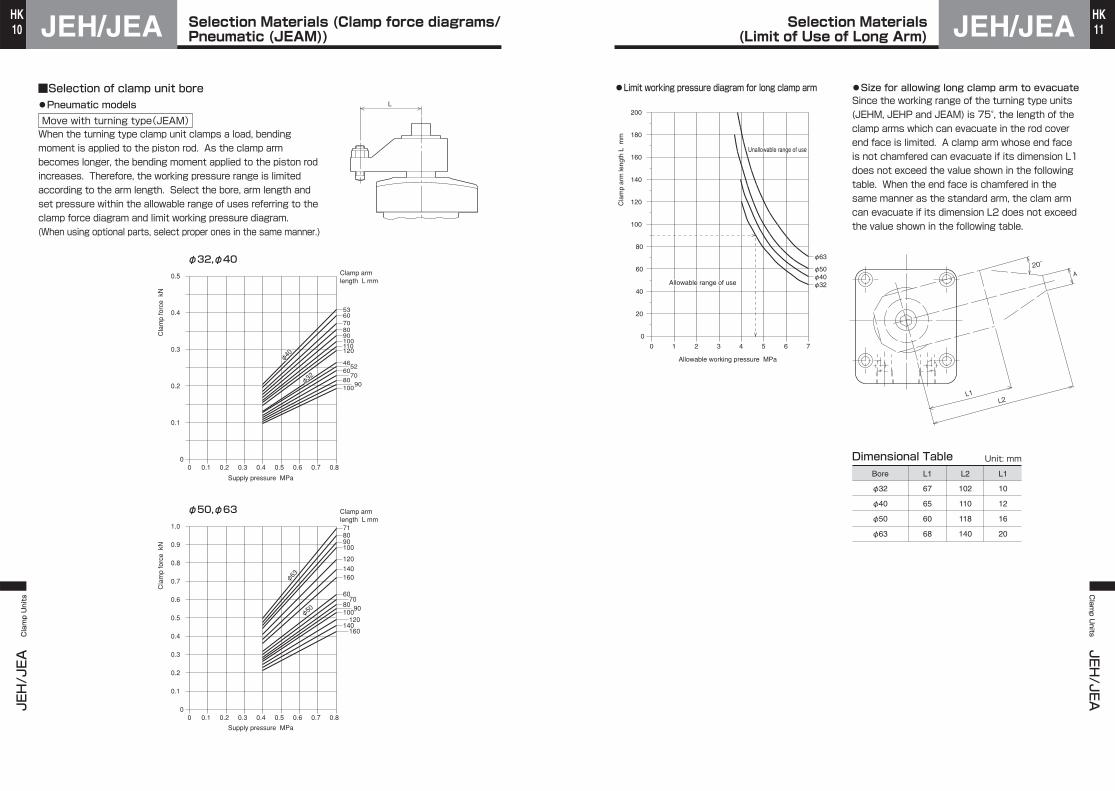
■Selection of clamp unit bore●Pneumatic models Move with turning type(JEAM)When the turning type clamp unit clamps a load, bending moment is applied to the piston rod. As the clamp arm becomes longer, the bending moment applied to the piston rod increases. Therefore, the working pressure range is limited according to the arm length. Select the bore, arm length and set pressure within the allowable range of uses referring to the clamp force diagram and limit working pressure diagram.(When using optional parts, select proper ones in the same manner.)
L
Clamp arm length L mm
Clamp arm length L mm
0.8
0.8
φ50
φ63
140
120
100
8090
71
90
140
10080
160
120
7060
160
1.0
0.9
0.8
0.7
0.6
0.10 0.2 0.3 0.4 0.5 0.6 0.70
0.5
0.4
0.3
0.2
0.1
φ50,φ63
8090
100
7060
5246
1201101009080706053
0.5
0.4
0.3
0.2
0.1
φ32,φ40
00.70.60.50.40.30.20.10
φφ3232
φφ4040
φ32
φ40
Cla
mp
forc
e k
NC
lam
p fo
rce
kN
Supply pressure MPa
Supply pressure MPa
●Limit working pressure diagram for long clamp arm ●Size for allowing long clamp arm to evacuateSince the working range of the turning type units (JEHM, JEHP and JEAM) is 75°, the length of the clamp arms which can evacuate in the rod cover end face is limited. A clamp arm whose end face is not chamfered can evacuate if its dimension L1 does not exceed the value shown in the following table. When the end face is chamfered in the same manner as the standard arm, the clam arm can evacuate if its dimension L2 does not exceed the value shown in the following table.
Bore
φ32
φ40
φ50
φ63
L1
67
65
60
68
L2
102
110
118
140
L1
10
12
16
20
Dimensional Table Unit: mm
20゚A
L1L2
φ63
φ40φ50
φ32
Cla
mp
arm
leng
th L
mm
200
180
160
140
120
100
80
60
40
20
Allowable working pressure MPa
0
76543210
Allowable range of useAllowable range of use
Unallowable range of useUnallowable range of use
Allowable range of use
Unallowable range of use
Selection Materials (Clamp force diagrams/Pneumatic (JEAM))
Selection Materials(Limit of Use of Long Arm)

JEH/JEAJEH/JEA Clamp Units
12HK
JEH/JEAClamp Units
JEH/JEA
13HK
A wide variation of compact units●Hydraulic (7 MPa) models and pneumatic models of the same size are available.●The new design reduces the overall length and promotes downsizing of jigs.●The newly applied gasket type seals on the rod cover and jig surface are easy to fit and reliable.
●The easy-to-use magnetic proximity sensor embedded in the body facilitates confirmation of clamping and unclamping state.
Nominal pressure
Proof test pressure
Working speed range
Working temperature range
Structure of cushioning
Adaptable fluid
Main Body Specifications: Hydraulic modelsSwing type
JEHS
Move with turning type
JEHM
Move after turning type
JEHP
Front mount type
JEHF
Rear mount type
JEHRType
None
Petroleum-based fluid
7 MPa
10.5 MPa
2 MPa 1 MPa1 MPa
8 to 100 mm/s 8 to 100 mm/s
1.5 MPaMinimum operating pressure
Note)
Without sensor……………-5 to +80℃With sensor………………-5 to +70℃
(No freezing)
Note) Adjust the flow control valve to obtain the 75° swing time of 0.5 sec or more.
Adaptable fluid
Lubrication
Proof test pressure
Working speed range
Working temperature range
Structure of cushioning
Main Body Specifications: Pneumatic modelsSwing type
JEAS
Move with turning type
JEAMType
None
Air
Unnecessary
0.1 to 0.8 MPa
1.2 MPa
0.4 to 0.8 MPa
30 to 100 mm/s
Working pressure range
Note) Adjust the speed controller to obtain the 75° swing time of 0.5 sec or more.
Note)
+5 to +60℃
Nominal pressurePressure given to a cylinder for convenience of naming.It is not always the same as the working pressure (rated pressure) that guarantees performance under the specified conditions.
Proof test pressureTest pressure against which a cylinder can withstand without unreliable performance at the return to nominal pressure.
Minimum operating pressureMinimum pressure at which cylinder installed horizontally operates under no load.
Note) ●The hydraulic models do not have air vents.
Terminologies
Hydraulic models Pneumatic models
Swing typeJEHS
Move with turning typeJEHM
Swing typeJEAS
Move with turning typeJEAM
Move after turning typeJEHP
Front mount typeJEHF
Rear mount typeJEHR
Type Straightmovement Turning
Product Lineup Unit: mm
Bore and StrokeNote) The strokes contained in the part numbers of turning type units indicate the full strokes.
One kind of stroke for each bore of the swing, move with turning and move after turning type unitsFor all bores of the front mount and rear mount type units, one of 10, 20, 30, 40, and 50 mm can be selected.
Unit: mm
Type Straightmovement Turning f32 f40 f50 f63
Hydraulic models
Pneumatic models
Swing type (link)JEHS
Move with turning typeJEHM
Move after turning typeJEHP
Front mount typeJEHF
Rear mount typeJEHR
Swing type (link)JEAS
Move with turning typeJEAM
f32 f40 f50 f63
Stroke
30Stroke
35Stroke
41Stroke
49
Full stroke Turning stroke11Straight movementclamp stroke
617
Stroke
10, 20, 30, 40, 50
Stroke
10, 20, 30, 40, 50
Stroke
30Stroke
35Stroke
41Stroke
49
Full stroke Turning stroke1420
Full stroke Turning stroke1825
Full stroke Turning stroke2229
Full stroke Turning stroke1117
Full stroke Turning stroke1319
Full stroke Turning stroke1724
Full stroke Turning stroke2128
Full stroke
17Full stroke
20Full stroke
25Full stroke
29
Swing type (link)JEHS
Move with turning typeJEHM
Move after turning typeJEHP
Front mount typeJEHF
Rear mount typeJEHR
Swing type (link)JEAS
Move with turning typeJEAM
Hydraulic models
Pneumatic models
Straight movementclamp stroke
6
Straight movementclamp stroke
6
Straight movementclamp stroke
6
Straight movementclamp stroke
7
Straight movementclamp stroke
7
Straight movementclamp stroke
7
Turning stroke11
Straight movementclamp stroke
6
Turning stroke14
Turning stroke18
Turning stroke22
Straight movementclamp stroke
6Straight movementclamp stroke
7Straight movementclamp stroke
7
Straight movementclamp stroke
7
Clamp Unit Clamp Unit
JEH/JEAJEH/JEA Clamp Units
14HK
JEH/JEAClamp Units
JEH/JEA
15HK
JEHM Move with turning typeJEHP Move after turning type
RightLeft
JEHS
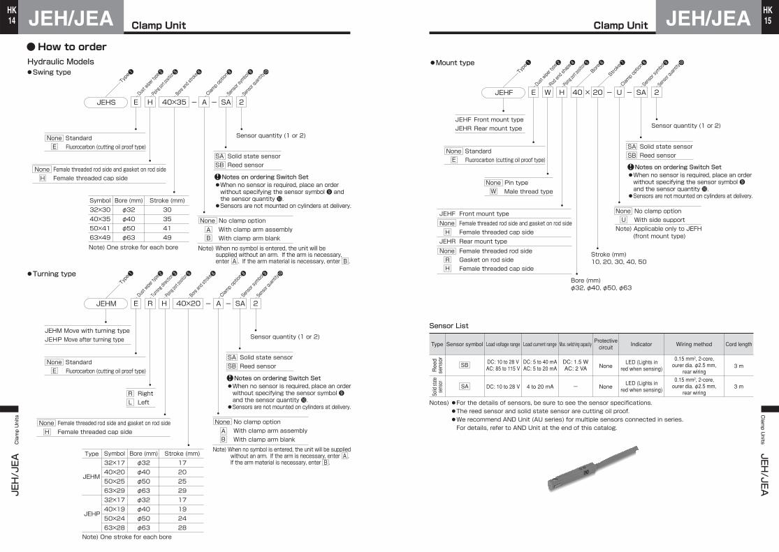
Hydraulic Models●Swing type
Sensor quantity (1 or 2)
Notes on ordering Switch Set●When no sensor is required, place an order without specifying the sensor symbol ❾ and the sensor quantity 10.●Sensors are not mounted on cylinders at delivery.
E H A- - 2SA40×35
JEHM
●Turning type
RE H A- - 2SA40×20
None Standard Fluorocarbon (cutting oil proof type)E
RL
None No clamp option With clamp arm assembly With clamp arm blankAB
SA Solid state sensorSB Reed sensor
None Female threaded rod side and gasket on rod side Female threaded cap sideH
Sensor quantity (1 or 2)
Stroke (mm)30354149
Bore (mm)φ32φ40φ50φ63
Symbol32×3040×3550×4163×49
Stroke (mm)1720252917192428
Bore (mm)φ32φ40φ50φ63φ32φ40φ50φ63
Symbol32×1740×2050×2563×2932×1740×1950×2463×28
Type
JEHM
JEHP
Note) One stroke for each bore
Note) One stroke for each bore Note) When no symbol is entered, the unit will be supplied without an arm. If the arm is necessary, enter A . If the arm material is necessary, enter B .
Type❶
Dust wiper type❷
Piping port position❺
Bore and stroke❻
Clamp option❽
Sensor symbol❾
Sensor quantity10
Type❶
Dust wiper type❷
Piping port position❺
Turning direction❸
Bore and stroke❻
Clamp option❽
Sensor symbol❾
Sensor quantity10
None Standard Fluorocarbon (cutting oil proof type)E
None Female threaded rod side and gasket on rod side Female threaded cap sideH
Notes on ordering Switch Set●When no sensor is required, place an order without specifying the sensor symbol ❾ and the sensor quantity 10.●Sensors are not mounted on cylinders at delivery.
SA Solid state sensorSB Reed sensor
None No clamp option With clamp arm assembly With clamp arm blankAB
Note) When no symbol is entered, the unit will be supplied without an arm. If the arm is necessary, enter A . If the arm material is necessary, enter B .
JEHF Front mount typeJEHR Rear mount type
JEHF Front mount type
JEHF
●Mount type
WE H U- - 2SA40 × 20
None Pin type Male thread typeW
Sensor quantity (1 or 2)
None No clamp option With side supportNote) Applicable only to JEFH
(front mount type)
U
JEHR Rear mount typeNone Female threaded rod side Gasket on rod side Female threaded cap sideRH
Stroke (mm)10, 20, 30, 40, 50
Bore (mm)φ32, φ40, φ50, φ63
Type Sensor symbol Load voltage range Load current range Max. switching capacityProtective
circuit Indicator Wiring method Cord length
Ree
dse
nsor
Solid
stat
ese
nsor
SB
SA DC: 10 to 28 V 4 to 20 mA
DC: 10 to 28 VAC: 85 to 115 V
DC: 5 to 40 mAAC: 5 to 20 mA
DC: 1.5 WAC: 2 VA
LED (Lights inred when sensing)
0.15 mm², 2-core,ourer dia. φ2.5 mm,
rear wiring0.15 mm², 2-core,
ourer dia. φ2.5 mm,rear wiring
LED (Lights inred when sensing)
None 3 m
3 mNone-
Notes) ●For the details of sensors, be sure to see the sensor specifications.●The reed sensor and solid state sensor are cutting oil proof.●We recommend AND Unit (AU series) for multiple sensors connected in series.For details, refer to AND Unit at the end of this catalog.
Sensor List
Sensor symbol❾
Type❶
Dust wiper type❷
Rod end shape❹
Piping port position❺
Bore❻
Stroke❼
Clamp option❽
Sensor quantity10
None Standard Fluorocarbon (cutting oil proof type)E
None Female threaded rod side and gasket on rod side Female threaded cap sideH
Notes on ordering Switch Set●When no sensor is required, place an order without specifying the sensor symbol ❾ and the sensor quantity 10.●Sensors are not mounted on cylinders at delivery.
SA Solid state sensorSB Reed sensor
Clamp Unit Clamp Unit
● How to order

JEH/JEAJEH/JEA Clamp Units
16HK
JEH/JEAClamp Units
JEH/JEA
17HK
JEAS
Pneumatic Models●Swing type
Sensor quantity (1 or 2)
H A- - 2SA40×35
JEAM
●Move with turning type
R H A- - 2SA40×20
Sensor quantity (1 or 2)
Stroke (mm)17202529
Bore (mm)φ32φ40φ50φ63
Symbol32×1740×2050×2563×29
Type
JEAM
Sensor symbol❾
Clamp option❽
Bore and stroke❻
Piping port position❺
Type❶
Sensor quantity10
Sensor symbol❾
Clamp option❽
Bore and stroke❻
Piping port position❺
Type❶
Turning direction❸
Sensor quantity10
None Female threaded rod side and gasket on rod side Female threaded cap sideH
None Female threaded rod side and gasket on rod side Female threaded cap sideH
Stroke (mm)30354149
Bore (mm)φ32φ40φ50φ63
Symbol32×3040×3550×4163×49
Notes on ordering Switch Set●When no sensor is required, place an order without specifying the sensor symbol ❾ and the sensor quantity 10.●Sensors are not mounted on cylinders at delivery.
SA Solid state sensorSB Reed sensor
None No clamp option With clamp arm assembly With clamp arm blankAB
Note) When no symbol is entered, the unit will be supplied without an arm. If the arm is necessary, enter A . If the arm material is necessary, enter B .
RightLeft
RL
Notes on ordering Switch Set●When no sensor is required, place an order without specifying the sensor symbol ❾ and the sensor quantity 10.●Sensors are not mounted on cylinders at delivery.
SA Solid state sensorSB Reed sensor
None No clamp option With clamp arm assembly With clamp arm blankAB
Note) When no symbol is entered, the unit will be supplied without an arm. If the arm is necessary, enter A . If the arm material is necessary, enter B .
Hydraulic Models/Swing type and turning typeWeight Table
1.53
2.24
3.76
5.93
1.59
2.33
3.88
6.21
1.50
2.29
3.84
5.90
f32
f40
f50
f63
Swing type (JEHS) Move with turning type (JEHM) Move after turning type (JEHP)
Standard type Female threadedcap side (H) Standard type Female threaded
cap side (H) Standard type Female threadedcap side (H)
1.56
2.38
3.95
6.17
1.62
2.42
4.02
6.40
1.66
2.50
4.06
6.57
Unit: kg
Hydraulic Models/Front mount type
Bore (mm)
1.16
1.63
2.68
3.92
1.22
1.73
2.78
4.19
f32
f40
f50
f63
JEHF (basic weight)
Pin type rod end Male thread type rod end (W)Added weight per mm of stroke
1.21
1.73
2.84
4.22
1.26
1.83
2.95
4.49
0.0065
0.0094
0.0147
0.0206
Unit: kg
Pneumatic Models/Swing type and turning type Unit: kg
Hydraulic Models/Rear mount type
Bore (mm)
1.18
1.68
2.80
4.04
1.17
1.67
2.79
4.03
1.24
1.78
2.91
4.32
f32
f40
f50
f63
JEHR (basic weight)
Pin type rod end Male thread type rod end (W)Added weight per mm of stroke
Standard type Gasket on rod side (R) Gasket on rod side (R)
1.23
1.78
2.96
4.34
1.22
1.77
2.95
4.33
1.28
1.87
3.07
4.62
0.0065
0.0094
0.0147
0.0206
Standard type
Unit: kg
Bore (mm)
1.53
2.24
3.76
5.93
1.59
2.33
3.88
6.21
1.50
2.29
3.84
5.90
f32
f40
f50
f63
Swing type (JEAS) Move with turning type (JEAM)
1.56
2.38
3.95
6.17
Bore (mm)
Type Sensor symbol Load voltage range Load current range Max. switching capacityProtective
circuit Indicator Wiring method Cord length
Ree
dse
nsor
Solid
stat
ese
nsor
SB
SA DC: 10 to 28 V 4 to 20 mA
DC: 10 to 28 VAC: 85 to 115 V
DC: 5 to 40 mAAC: 5 to 20 mA
DC: 1.5 WAC: 2 VA
LED (Lights inred when sensing)
0.15 mm², 2-core,ourer dia. φ2.5 mm,
rear wiring0.15 mm², 2-core,
ourer dia. φ2.5 mm,rear wiring
LED (Lights inred when sensing)
None 3 m
3 mNone-
Notes) ●For the details of sensors, be sure to see the sensor specifications.●The reed sensor and solid state sensor are cutting oil proof.●We recommend AND Unit (AU series) for multiple sensors connected in series.For details, refer to AND Unit at the end of this catalog.
Sensor List
Standard type Female threadedcap side (H) Standard type Female threaded
cap side (H)
Standard type Female threadedcap side (H) Standard type Female threaded
cap side (H)
Female threadedcap side (H)
Female threadedcap side (H)
Clamp Unit Clamp Unit
● How to order

JEHJEH Clamp Units
18HK
JEHClamp Units
JEH19HK
Unit: mm Unit: mm
Female threaded rod side and gasket on rod sideJEHS A-Bore×strokeE
Female threaded cap side
AH
15゚ 2-(AP)
AJ
M
J φP
AF
φT
φS
AR
R
2 Q
Max. A (Clamping position)
φX2-AC
4-φAB AK (Adjustment range)
φD
Y
Z
V U
NAG
W
φC
K
A B
H
I
AD
AE
G
□F
E(With ↑ on clamp port side)
Excess stroke
Retraction Extension
AH
15゚
A
2-ANAQAQ
AM
AL
AJ
M
J φP
AF
φT
φS
AR
R
2 Q
Max. AI (Clamping position)
4-φAB AK (Adjustment range)
φD
(Y)
(Z)
V U
N
AG
W
φC
H
I
AD
AE
G
□F
Excess stroke
L
K
AA
AA
AA
AAExtension Retraction
Note) The port of the rod cover cannot be used.
JEHS E H
JEH/TJEHS Bore
A-Bore×stroke
Optional parts
● A Clamp arm assembly ● B Clamp arm blank
Dimensional TableSymbol
Bore
30
35
41
49
74
83
97
110
30°
25°
30°
30°
30°
35°
35°
35°
6.6
9
11
13.5
32
38
46
58
22
26
30
38
20
25
29
35
6
8
10
12
63
69
79
88
2
3
4
4
5
5
5
5
73
85
94
112
Rc1/8
Rc1/4
Rc1/4
Rc3/8
Rc1/8
Rc1/4
Rc1/4
Rc3/8
Rc1/16
Rc1/16
Rc1/16
Rc1/8
f32
f40
f50
f63
Stroke A AA AB AC AD AE AF AG AH AI AJ AK AL
11
11
13
17
-0.1-0.4
-0.1-0.4
-0.1-0.4
-0.1-0.4
Symbol
Bore
9
11
11
15
18
22
28
36
63
72
85
96
20
25
32
40
0-0.3
0-0.3
0-0.3
0-0.3
55
65
80
95
30
33
35
42
55
63
70
85
70
78
88
106
43
49
58
67
35
42
50
62
78
91
108
129
f32
f40
f50
f63
ANAM (AP) AQ AR B C ED F G H I J
Symbol
Bore
28
30
35
36
11
12
13
14
11
20
20
20
16
20
24
32
18.5
23.5
30.5
38.5
8
10
13
17
10.5
12
15
19
6
8
10
12
8
10
12
16
41
42
49
54
33
41
48
56
26
31
37
45
8
8
8
10
30
39
40
48
32
35
44
51
f32
f40
f50
f63
LK M N P Q R TS U V W X Y Z
Symbol
Bore
46
56
66
80
10
10
14
14
8
8
10
12
26
31
37
45
9
11
14
18
6H9
8H9
10H9
12H9
8H9
10H9
12H9
16H9
5
6
7
10
52
64
76
92
19.5
23
28
36
18
22
28
36
2
3
4
4
5
5
5
5
25
30
35
42
M6
M8
M10
M12
125
160
200
200
f32
f40
f50
f63
BA C D E F G NH L M Q R S T U YX
寸法表
22
26
30
38
0-0.2
0-0.2
0-0.2
0-0.2
11
11
13
17
+0.2 0
+0.2 0
+0.2 0
+0.2 0
30゚
BMN
U
(Adjustment range)T
S
L
A
30゚HDC
φG
RE
XφF
Q
MN
Y
30゚HDC
φG
RE
φF
JEH/TJEHS Bore
Clamp UnitHydraulic Models of Swing Type
Clamp UnitHydraulic Models of Swing Type
CAD/DATAis available.JEH/TJEHS Bore

JEHJEH Clamp Units
20HK
JEHClamp Units
JEH21HK
Unit: mm Unit: mm
Optional parts
Dimensional Table
Dimensional Table
69.2
77.2
91.5
105
36
45
58
72
34
36
41
42
22
26
32
38
11.2
13.2
16.5
21
8
8
8
10
30
39
40
48
32
35
44
51
6.6
6.6
9
11
11
11
14
17.5
11
14
14
11
M8
M10
M12
M16
18
18
23
32
10
12
16
20
24
28
34
42
46
53
60
71
6
8
10
12
32
33
37
38
6
6
7
7
11
14
18
22
2
3
4
4
5
5
5
5
79
92
105
123
9
11
11
15
Rc1/8
Rc1/4
Rc1/4
Rc3/8
Rc1/8
Rc1/4
Rc1/4
Rc3/8
f32
f40
f50
f63
AA AB AA C AFAEAHAG
TurningStraightmovement AJ AK AL AM ANAD
30°
35°
35°
35°
30°
25°
30°
30°
30
33
35
42
69
79
96
107
20
25
32
40
55
63
70
85
43
49
58
67
35
39
44
53
78
88
102
120
28
30
35
36
11
12
13
14
Rc1/16
Rc1/16
Rc1/16
Rc1/8
70
78
88
106
f32
f40
f50
f63
AQ B(AP) C E GF H I J K L
M N P Q R TS U V W X Y Z
D
f32
f40
f50
f63
55
65
80
95
0 -0.3
0 -0.3
0 -0.3
0 -0.3
46
53
60
71
10
12
16
20
8
10
12
16
18
23
29
36
52
61
70
83
36
45
58
72
24
28
34
42
2
3
4
4
5
5
5
5
25
30
35
42
M6
M8
M10
M12
125
160
160
200
f32
f40
f50
f63
B NGCA L M R S T U YX
20
25
32
40
±0.02
±0.02
±0.02
±0.02
B
20゚ M
N
U
(Adjustment range)T
S
15゚
φG
L
AC
R
X
M
N
15゚
φG
YC
R
Symbol
Bore
Symbol
Bore
Symbol
Bore
Symbol
Bore
JEH/TJEHM Bore
● A Clamp arm assembly ● B Clamp arm blank
Clamp UnitHydraulic Models of Move with Turning Type
Clamp UnitHydraulic Models of Move with Turning Type
CAD/DATAis available.JEH/TJEHM Bore
Female threaded rod side and gasket on rod sideJEHM E R
JEHM E R HFemale threaded cap side
N
ACP
A
M
K
75゚
Clockwise turning
75゚
Counterclockwiseturning
AE
15゚ 2-(AP)
AJ
W
J
(Turning)AH AG AF
Y depth Z
15゚
φQ
φC
AB
AK (Adjustment range)
AD
φDT
T
R
S
L
B
2-X
Spot facing dia. V4-φU
AA
H
I
G
□F
E
(Straight movement)
AJ
AF
AE
AQ
AL
K
M
N
ACP
A
15゚
AQ
2-ANAM
W
J 15゚ φC
AB
AK (Adjustment range)
AD
φD
T
T
(R)
(S)
AA
H
I
G
□F
Note) The port of the rod cover cannot be used.
JEH/TJEHM Bore
A-Bore×stroke
A-Bore×stroke
75゚
Clockwise turning
75゚
Counterclockwiseturning
Spot facing dia. V4-φU
Retraction Extension
(With ↑ on clamp port side)
(Turning)AH AG(Straight movement)
Y depth Z
Extension Retraction

JEHJEH Clamp Units
22HK
JEHClamp Units
JEH23HK
Unit: mm Unit: mm
Female threaded rod side and gasket on rod side
Female threaded cap side
N K
MACP
A
15゚
AJ
AE
B
2-(AP)
W
J
AF
15゚
φQ
φC
AB
AD
φDT
T
R
S
L
AA
H
I
G
□F
E
AQAQ
15゚ KN
MACP
A
AJ
AE
H
AL
2-ANAM
W
J
AF
15゚ φC
AB
AD
φD
T
T
(R)
(S)
AA
I
G
□F
Note) The port of the rod cover cannot be used.
JEHP E R H
JEHP E R
JEH/TJEHP Bore
A-Bore×stroke
A-Bore×stroke
Extension Retraction
75゚
Clockwise turning
Spot facing dia. V4-φU
Retraction Extension
Y depth Z
2-X(With ↑ on clamp port side)
AG
AK (Adjustment range)
(Straight movement)
75゚
Clockwise turning
75゚
Counterclockwiseturning
Spot facing dia. V
75゚
Counterclockwiseturning
4-φU
Y depth Z
AG
AK (Adjustment range)
(Straight movement)
Optional parts
Dimensional Table
69.2
77.2
91.5
105
36
45
58
72
34
36
41
42
22
26
32
38
11.2
13.2
16.5
21
8
8
8
10
30
39
40
48
32
35
44
51
6.6
6.6
9
11
11
11
14
17.5
11
14
14
11
M8
M10
M12
M16
18
18
23
32
10
12
16
20
24
28
34
42
46
53
60
71
6
8
10
12
32
33
37
38
6
6
7
7
2
3
4
4
5
5
5
5
89
99
110
132
9
11
11
15
Rc1/8
Rc1/4
Rc1/4
Rc3/8
Rc1/8
Rc1/4
Rc1/4
Rc3/8
f32
f40
f50
f63
AA AB AA AC FAEAG
Straightmovement AJ AK AL AM ANAD
30°
35°
35°
35°
30°
25°
30°
30°
30
33
35
42
82
89
106
122
20
25
32
40
55
63
70
85
43
49
58
67
35
39
44
53
78
88
102
120
28
30
35
36
11
12
13
14
Rc1/16
Rc1/16
Rc1/16
Rc1/8
70
78
88
106
f32
f40
f50
f63
AQ B(AP) C E GF H I J K L
M N P Q R TS U V W X Y Z
55
65
80
95
0 -0.3
0 -0.3
0 -0.3
0 -0.3
D
f32
f40
f50
f63
46
53
60
71
10
12
16
20
8
10
12
16
18
23
29
36
52
61
70
83
36
45
58
72
24
28
34
42
2
3
4
4
5
5
5
5
25
30
35
42
M6
M8
M10
M12
125
160
160
200
f32
f40
f50
f63
B NGCA L M R S T U YX
20
25
32
40
±0.02
±0.02
±0.02
±0.02
B
20゚ M
N
U
(Adjustment range)T
S
15゚
φG
L
AC
R
X
M
N
15゚
φG
YC
R
Symbol
Bore
Symbol
Bore
Symbol
Bore
Symbol
Bore
JEH/TJEHP Bore
● A Clamp arm assembly ● B Clamp arm blank
Clamp UnitHydraulic Models of Move after Turning Type
Clamp UnitHydraulic Models of Move after Turning Type
CAD/DATAis available.JEH/TJEHP Bore

JEHJEH Clamp Units
24HK
JEHClamp Units
JEH25HK
Unit: mm Unit: mm
Female threaded rod side and gasket on rod sideJEHF × strokeBoreE
JEHF E H
Side supportJEHF E
Female threaded cap side
B+stroke
H
15゚ φS
φP
R
Q
K
Min.A
AF
2-(AP)
W
J
M
φN
φC φDT
T
Y
Z
L
2-X
Spot facing dia. V4-φU
I
G
□F
E
(With ↑ on clamp port side)
AQAQ
2-AN AM
AL+stroke
H
15゚
φS
φP
R
Q
K
Min.A
AF W
J
M
φC φD
T
T
(Y)
(Z)
Spot facing dia. V4-φU
I
G
□F
4-S depth T
φY
□R
GHG
FDF
B(L)
M
C A
2-(X)
(N)
(E)
2
J
K
O-ring usedφP
Spot facing dia. V depth W
4-φUφQ
(Extension)
(Retraction)
Extension
Note) Each port is provided with a plug. Be sure to cover the unused ports with their plugs.
Note) The port of the rod cover cannot be used.
× strokeBore
× stroke -UBore
Retraction Extension
Extension Retraction
RetractionRetraction
Male thread type rod endJEHF E W H Bore × Stroke
46
50
58
63
20
25
32
40
30
35
40
50
M14×1.5
M20×1.5
M24×1.5
M30×1.5
17
22
27
32
10
12
14
16
f32
f40
f50
f63
CA MA MB MD ME
Dimensional Table
8
10
13
17
10.5
12
15
19
6H9
8H9
10H9
12H9
6.6
6.6
9
11
11
11
14
17.5
11
14
14
11
30
39
40
48
32
35
44
51
Rc1/8
Rc1/4
Rc1/4
Rc3/8
Rc1/8
Rc1/4
Rc1/4
Rc3/8
f32
f40
f50
f63
AF AL AM AN (AP) AQ B C DA
30°
35°
35°
35°
30°
25°
30°
30°
46
50
58
63
30
33
35
42
55
63
70
85
70
78
88
106
43
49
58
67
35
39
44
53
78
88
102
120
28
30
35
36
11
12
13
14
3
4
5
5
8
8
8
10
18.5
23.5
30.5
38.5
43
50
53
63
9
11
11
15
33
37
44
47
20
25
32
40
Rc1/16
Rc1/16
Rc1/16
Rc1/8
f32
f40
f50
f63
PE F G H I J K L M N
Q R TS U V W X Y Z
11
11
13
17
-0.1 -0.4
-0.1 -0.4
-0.1 -0.4
-0.1 -0.4
55
65
80
95
0 -0.3
0 -0.3
0 -0.3
0 -0.3
f32
f40
f50
f63
Dimensional Table
Rc1/8
Rc1/4
Rc1/4
Rc3/8
f32
f40
f50
f63
B C D (E) F G H J (N) K (L) MA
97
112
134
162
66
70
74
74
82
94
112
138
46
46
46
46
30
33
35
42
10
12
14
14
13
13
13
12
20
20
20
22
37
41
46
55
72
80
90
108
11
12
13
14
34
39
46
55
8.5
8.5
8.5
10.5
14
14
14
16
55
63
70
85
M6
M6
M8
M10
15
13
18
22
6.6
9
11
13.5
11
14
17.5
20
6.5
8.5
11
13
+0.5 +0.2
+0.5 +0.2
+0.5 +0.2
+0.5 +0.2
55
65
80
95
P10A
P10A
P10A
P12
Rc1/16
Rc1/16
Rc1/16
Rc1/8
f32
f40
f50
f63
YP Q O-ring used R S T U V W (X)
Dimensional Table: U Side port
MB
Width acrossflats MD
5 ME
MA Min.A
φC
Symbol
Bore
Symbol
Bore
Symbol
Bore
Symbol
Bore
Symbol
Bore
Symbol
Bore
Clamp UnitHydraulic Models of Front Mount Type
Clamp UnitHydraulic Models of Front Mount Type
CAD/DATAis available.JEH/TJEHF Bore

JEHJEH Clamp Units
26HK
JEHClamp Units
JEH27HK
Unit: mm Unit: mm
Female threaded rod sideJEHR E
Female threaded cap sideJEHR E H
JEHR E RGasket type on rod side
B+stroke
φRB
RA
Min.A K
L
H
φS
φP
R
Q
AF
J
M
φC φD
T
T
2-X
Spot facing dia. V depth W
4-φU
I
G
□F
E
(With ↑ on clamp port side)
P10AO-ring used
EA
B+stroke
φRBh8
RA
Min.A K
H
φSH9
φP
R
Q
AF
J
M
φC φDT
T
2-φ8.5, spot facing φ14
Spot facing dia. V depth W
4-φU
I
G
□F
E
(With ↑ on clamp port side)
AQAQ
AL+stroke
φRB
Min.A K
RA 2-AN AM
H
φS
φP
R
Q
AF
J
M
φC φDT
T
Spot facing dia. V depth W
4-φU
I
G
□F
Note) The port of the rod cover cannot be used.
× strokeBore
× strokeBore
× strokeBore
Extension Retraction
Retraction Extension
Retraction Extension
Male thread type rod end
64
66
70
75
20
25
32
40
30
35
40
50
M14×1.5
M20×1.5
M24×1.5
M30×1.5
17
22
27
32
10
12
14
16
f32
f40
f50
f63
CA MA MB MD ME
Dimensional Table
64
66
70
75
78
88
102
120
21.5
23.5
27.5
27.5
10.5
11.5
12.5
13.5
3
4
5
5
18.5
23.5
30.5
38.5
8
10
13
17
10.5
12
15
19
6
6
7
8
38h8
44h8
50h8
58h8
6H9
8H9
10H9
12H9
6.6
6.6
9
11
11
11
14
17.5
6.5
6.5
8.5
11
43.5
50.5
53.5
63.5
9
11
11
15
33.5
37.5
44.5
47.5
20
25
32
40
30
33
35
42
24
29
33
37
55
63
70
85
70
78
88
106
43
49
58
67
35
39
44
53
Rc1/8
Rc1/4
Rc1/4
Rc3/8
Rc1/8
Rc1/4
Rc1/4
Rc3/8
f32
f40
f50
f63
AF AL AA BM AQ C E EA GF H IAN
30°
35°
35°
35°
30°
25°
30°
30°
f32
f40
f50
f63
K LJ M P Q R RA RB S T U WV X
11
11
13
17
-0.1 -0.4
-0.1 -0.4
-0.1 -0.4
-0.1 -0.4
55
65
80
95
0 -0.3
0 -0.3
0 -0.3
0 -0.3
D
Dimensional Table
Min.A
φC
MB
Width acrossflats MD
5 ME
MA
Symbol
Bore
Symbol
Bore
Symbol
Bore
JEHR E W H Bore × Stroke
Clamp UnitHydraulic Models of Rear Mount Type
Clamp UnitHydraulic Models of Rear Mount Type
CAD/DATAis available.JEH/TJEHR Bore

JEAJEA Clamp Units
28HK
JEAClamp Units
JEA29HK
Unit: mm Unit: mm
Female threaded rod side and gasket on rod sideJEAS
Female threaded cap sideJEAS H
AH
15゚ 2-(AP)
AJ
M
J φP
AF
φT
φS
AR
R
2 Q
Max. AI (Clamping position)
φX2-AC
4-φAB AK (Adjustment range)
φD
Y
Z
AA
AA
V U
NAG
W
φC
K
A B
H
I
AD
AE
G
□F
E(With ↑ on clamp port side)
Excess stroke
AH
15゚
A
2-ANAQAQ
AM
AL
AJ
M
J φP
AF
φT
φS
AR
R
2 Q
Max. AI (Clamping position)
4-φAB AK (Adjustment range)
φD
(Y)
(Z)
V U
N
AG
W
φC
H
I
AD
AE
G
□F
Excess stroke
L
K
AA
AA
Note) The port of the rod cover cannot be used.
A-Bore×stroke
A-Bore×stroke
Extension Retraction
Retraction Extension
Optional parts
30
35
41
49
74
83
97
110
30°
25°
30°
30°
30°
35°
35°
35°
6.6
9
11
13.5
32
38
46
58
22
26
30
38
20
25
29
35
6
8
10
12
63
69
79
88
2
3
4
4
5
5
5
5
73
85
94
112
Rc1/8
Rc1/4
Rc1/4
Rc3/8
Rc1/8
Rc1/4
Rc1/4
Rc3/8
Rc1/16
Rc1/16
Rc1/16
Rc1/8
f32
f40
f50
f63
Stroke A AA AB AC AD AE AF AG AH AI AJ AK AL
11
11
13
17
-0.1 -0.4
-0.1 -0.4
-0.1 -0.4
-0.1 -0.4
9
11
11
15
18
22
28
36
63
72
85
96
20
25
32
40
0 -0.3
0 -0.3
0 -0.3
0 -0.3
55
65
80
95
30
33
35
42
55
63
70
85
70
78
88
106
43
49
58
67
35
42
50
62
78
91
108
129
f32
f40
f50
f63
ANAM (AP) AQ AR B C ED F G H I J
28
30
35
36
11
12
13
14
11
20
20
20
16
20
24
32
18.5
23.5
30.5
38.5
8
10
13
17
10.5
12
15
19
6
8
10
12
8
10
12
16
41
42
49
54
33
41
48
56
26
31
37
45
8
8
8
10
30
39
40
48
32
35
44
51
f32
f40
f50
f63
LK M N P Q R TS U V W X Y Z
46
56
66
80
10
10
14
14
8
8
10
12
26
31
37
45
9
11
14
18
6
8
10
12
8
10
12
16
5
6
7
10
52
64
76
92
19.5
23
28
36
18
22
28
36
2
3
4
4
5
5
5
5
25
30
35
42
M6
M8
M10
M12
125
160
200
200
f32
f40
f50
f63
BA C D E F G NH L M Q R S T U YX
Dimensional Table
22
26
30
38
0 -0.2
0 -0.2
0 -0.2
0 -0.2
11
11
13
17
+0.2 0
+0.2 0
+0.2 0
+0.2 0
Dimensional Table
30゚
BMN
U
(Adjustment range)T
S
L
A
30゚ HDC
φGH9
RE
XφFH9
Q
MN
Y
30゚ HDC
φGH9
RE
φFH9
Symbol
Bore
Symbol
Bore
Symbol
Bore
Symbol
Bore
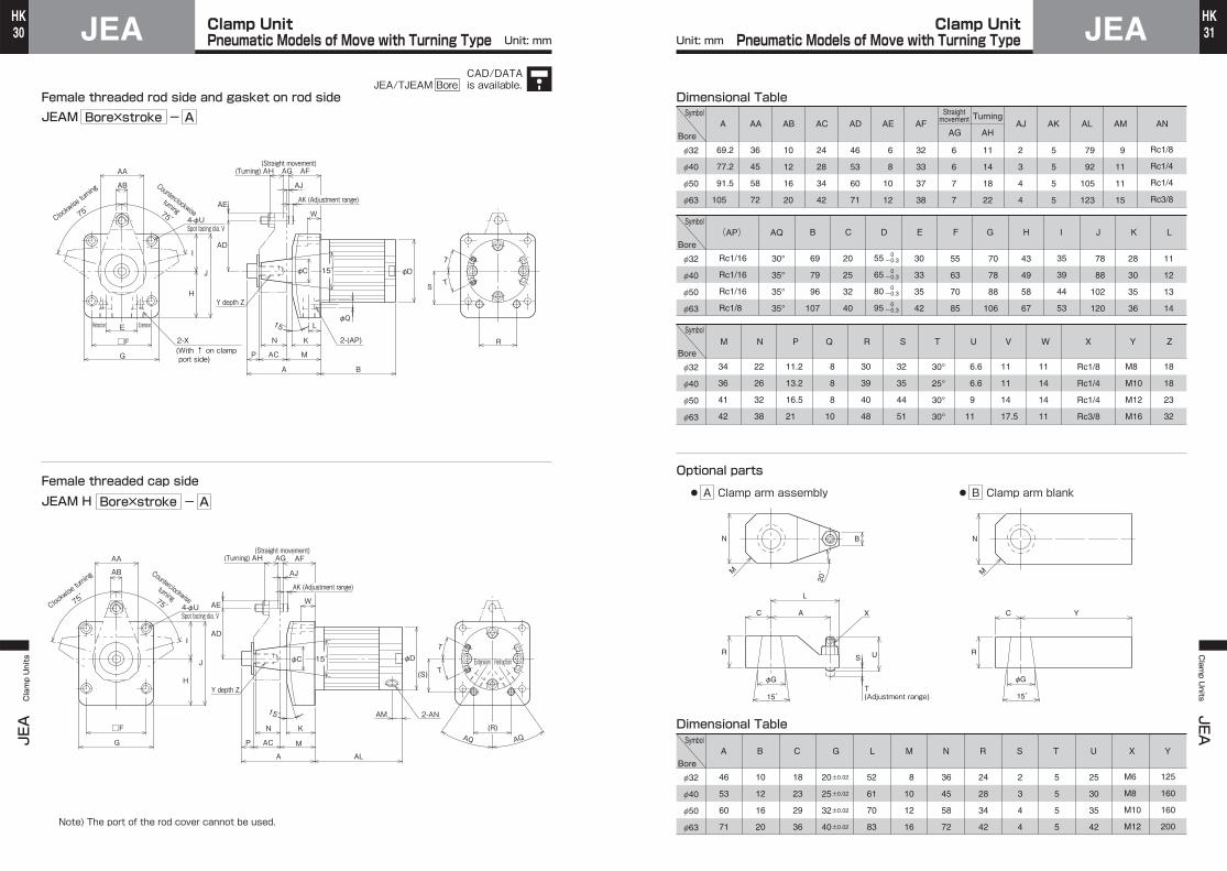
● A Clamp arm assembly ● B Clamp arm blank
Clamp UnitPneumatic Models of Swing Type
Clamp UnitPneumatic Models of Swing Type
CAD/DATAis available.JEA/TJEAS Bore
JEAJEA Clamp Units
30HK
JEAClamp Units
JEA31HK
Unit: mm Unit: mm
Female threaded rod side and gasket on rod sideJEAM
JEAM HFemale threaded cap side
N
ACP
A
M
K
AE
15゚ 2-(AP)
AJ
W
J
AF
15゚
φQ
φC
AB
AK (Adjustment range)
AD
φDT
T
R
S
L
B
AA
H
I
G
□F
E
AJ
AF
AE
AQ
AL
K
M
N
ACP
A
15゚
AQ
2-ANAM
W
J 15゚ φC
AB
AD
φD
T
T
(R)
(S)
AA
H
I
G
□F
Note) The port of the rod cover cannot be used.
A-Bore×stroke
A-Bore×stroke
75゚
Clockwise turning
75゚
Counterclockwiseturning
Spot facing dia. V4-φU
Retraction Extension
75゚
Clockwise turning
75゚
Counterclockwiseturning
Spot facing dia. V4-φU
Y depth Z
2-X(With ↑ on clamp port side)
Y depth Z
(Turning)AH AG
AK (Adjustment range)
(Straight movement)
(Turning)AH AG(Straight movement)
Extension Retraction
Optional parts
Dimensional Table
Dimensional Table
69.2
77.2
91.5
105
36
45
58
72
34
36
41
42
22
26
32
38
11.2
13.2
16.5
21
8
8
8
10
30
39
40
48
32
35
44
51
6.6
6.6
9
11
11
11
14
17.5
11
14
14
11
M8
M10
M12
M16
18
18
23
32
10
12
16
20
24
28
34
42
46
53
60
71
6
8
10
12
32
33
37
38
6
6
7
7
11
14
18
22
2
3
4
4
5
5
5
5
79
92
105
123
9
11
11
15
Rc1/8
Rc1/4
Rc1/4
Rc3/8
Rc1/8
Rc1/4
Rc1/4
Rc3/8
f32
f40
f50
f63
AA AB AA C AFAE AJ AK AL AM ANAD
30°
35°
35°
35°
30°
25°
30°
30°
30
33
35
42
69
79
96
107
20
25
32
40
55
63
70
85
43
49
58
67
35
39
44
53
78
88
102
120
28
30
35
36
11
12
13
14
Rc1/16
Rc1/16
Rc1/16
Rc1/8
70
78
88
106
f32
f40
f50
f63
AQ B(AP) C E GF H I J K L
M N P Q R TS U V W X Y Z
55
65
80
95
0 -0.3
0 -0.3
0 -0.3
0 -0.3
D
f32
f40
f50
f63
46
53
60
71
10
12
16
20
8
10
12
16
18
23
29
36
52
61
70
83
36
45
58
72
24
28
34
42
2
3
4
4
5
5
5
5
25
30
35
42
M6
M8
M10
M12
125
160
160
200
f32
f40
f50
f63
B NGCA L M R S T U YX
20
25
32
40
±0.02
±0.02
±0.02
±0.02
B
20゚ M
N
U
(Adjustment range)T
S
15゚
φG
L
AC
R
X
M
N
15゚
φG
YC
R
Symbol
Bore
Symbol
Bore
Symbol
Bore
Symbol
Bore
● A Clamp arm assembly ● B Clamp arm blank
AHAG
TurningStraightmovement
Clamp UnitPneumatic Models of Move with Turning Type
Clamp UnitPneumatic Models of Move with Turning Type
CAD/DATAis available.JEA/TJEAM Bore

JEH/JEAJEH/JEA Clamp Units
32HK
JEH/JEAClamp Units
JEH/JEA
33HK
Unit: mm
Sensor mounting position
●Female threaded rod side and gasket on rod side ●Female threaded cap side
UX1
UX2
UX1
UX3
Symbol
Bore
9
10.5
12.5
13
f32
f40
f50
f63
UX1
24
26.5
31.5
34
UX2
34
39.5
40.5
50
UX3
5
6.5
8.5
9
UX1
28
30.5
35.5
38
UX2
38
43.5
44.5
54
UX3
SA (solid state sensor)
SA (solid state sensor)
SA (solid state sensor)
SB (reed sensor)
SB (reed sensor)
SB (reed sensor)
Dimensional Table: Swing type, front mount type, rear mount type
28
32.5
39.5
44
f32
f40
f50
f63
UX1
24
26.5
31.5
34
UX2
34
39.5
40.5
50
UX3
24
28.5
35.5
40
UX1
28
30.5
35.5
38
UX2
38
43.5
44.5
54
UX3
Dimensional Table: Move with turning type
32
34
41
49.5
f32
f40
f50
f63
UX1
33
36
41
44.5
UX2
40
46
45
54.5
UX3
28
30
37
45.5
UX1
37
40
45
48.5
UX2
44
50
49
58.5
UX3
Dimensional Table: Move after turning type
Note) Dimension UX indicates the optimum sensor mounting position for detection of stroke end.
Note)
Note)
Note) Note that the sensor end part protrudes 2.5 mm from the cover end (the sensor overall length is 26.5).
Note) Note that the sensor end part protrudes 2.5 mm from the cover end (the sensor overall length is 26.5).
Symbol
Bore
Symbol
Bore
Type With cord (3 m)
Sensor SpecificationsSolid state sensor
SA
Rear
Reed sensor
SB
Contact type
Note) When using any induction load (relay, etc.), be sure to provide a protective circuit (SK-100) with the load.
Wiring direction
Load voltage range
Load current range
Internal voltage drop
Max. switching capacity
Leakage current
Response time
Insulation resistance
Withstand voltage
Impact resistance
4 to 20 mA (at 25℃, 10 mA at 70℃)
4.5 V or less
-
1 mA or less (24 V DC, 25℃)
10 to 28 V DC
5 to 40 mA
10 to 28 V DC 85 to 115 V AC
5 to 20 mA
1 ms or less
100 Ω or more (between case and cord) on 500-V DC megger
500 V AC for 1 min (between case and cord)
300 m/s² (non-repeating)
3 V or less
DC1.5W・AC2VA
0
Ambient temperature
Wiring method
Protection structure
Indicator
Vibration resistance Double amplitude of 1.5 mm 10 to 55 Hz (90 m/s²) Double amplitude of 1.5 mm 10 to 55 Hz (90 m/s²)Resonance frequency 2750±250 Hz
-5 to +70℃ (No freezing)
100 V, 0.15 mm², 2-core, outer dia. φ2.5 mm
IEC IP67, JIS C9020 (immersion-proof type)
Red LED turns on when sensing.
Small relay, programmable controllerApplicable load
Electric circuit
Dimensional Drawings Unit: mm
Sensormaincircuit
LoadBrown (+)
Blue (-)
DC10to 28V
Brown (+)
Blue (-)
Compact magnetic proximity sensors.●Cutting fluid proof sensors.●Since the sensor is embedded in the body, it does not protrude from the body.
φ2.5
Reed sensor 11.5Solid state sensor 7.5
26.5
Max. sensitivity position
Indicator
Set screw M2.5 with slotted head
8
±1060
3000
4.6
4
Clamp UnitClamp Unit
Special Sensor Specifi cations
JEH/JEAJEH/JEA Clamp Units
34HK
JEH/JEAClamp Units
JEH/JEA
35HK
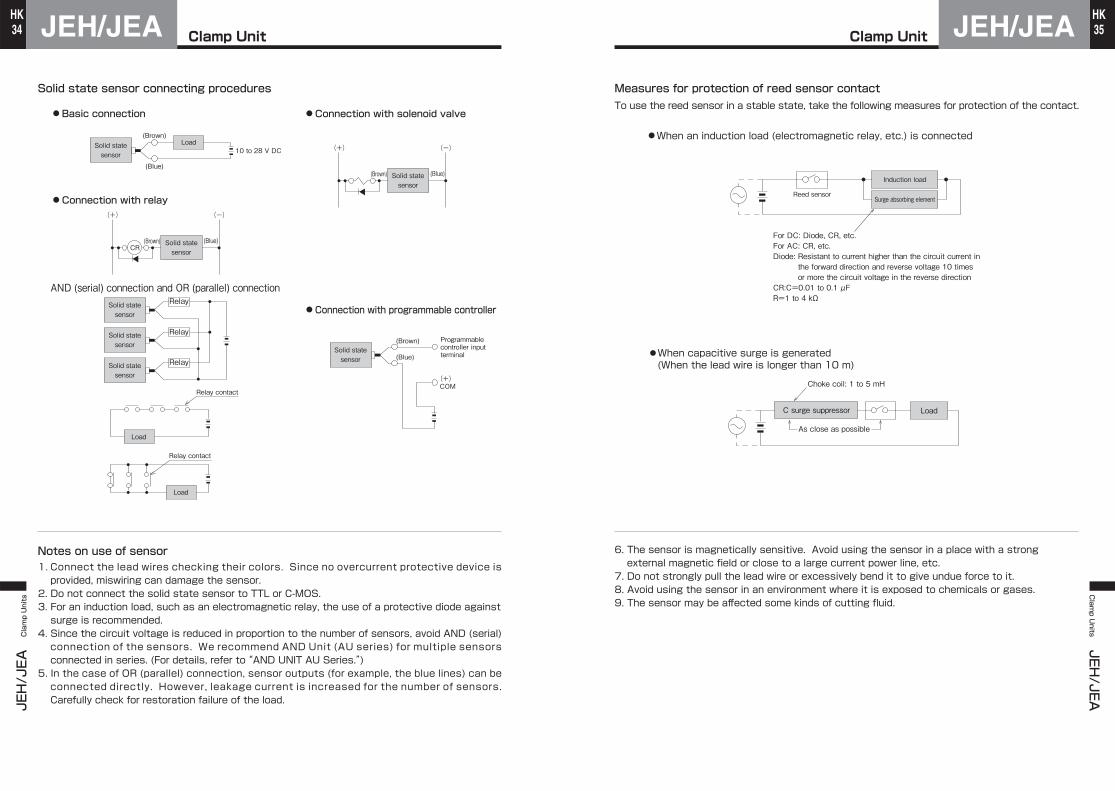
Solid state sensor connecting procedures
Notes on use of sensor1. Connect the lead wires checking their colors. Since no overcurrent protective device is provided, miswiring can damage the sensor.
2. Do not connect the solid state sensor to TTL or C-MOS.3. For an induction load, such as an electromagnetic relay, the use of a protective diode against surge is recommended.
4. Since the circuit voltage is reduced in proportion to the number of sensors, avoid AND (serial) connection of the sensors. We recommend AND Unit (AU series) for multiple sensors connected in series. (For details, refer to “AND UNIT AU Series.”)
5. In the case of OR (parallel) connection, sensor outputs (for example, the blue lines) can be connected directly. However, leakage current is increased for the number of sensors. Carefully check for restoration failure of the load.
● Basic connection ● Connection with solenoid valve
● Connection with programmable controller
● Connection with relay
Solid statesensor
(Brown)
(Brown)
(Blue)
(Brown) Programmablecontroller inputterminal(Blue)
(+) (-)
(Blue)
Load10 to 28 V DC
CR
(Brown)
(+) (-)
(Blue)
Relay
Load
Relay contact
Relay contact
Load
AND (serial) connection and OR (parallel) connection
(+)COM
Solid statesensor
Solid statesensor
Solid statesensor
Solid statesensor
Solid statesensor
Solid statesensor
Relay
Relay
Measures for protection of reed sensor contact
6. The sensor is magnetically sensitive. Avoid using the sensor in a place with a strongexternal magnetic field or close to a large current power line, etc.
7. Do not strongly pull the lead wire or excessively bend it to give undue force to it.8. Avoid using the sensor in an environment where it is exposed to chemicals or gases.9. The sensor may be affected some kinds of cutting fluid.
To use the reed sensor in a stable state, take the following measures for protection of the contact.
Induction load
Surge absorbing elementReed sensor
For DC: Diode, CR, etc.For AC: CR, etc.Diode: Resistant to current higher than the circuit current in
the forward direction and reverse voltage 10 times or more the circuit voltage in the reverse direction
CR:C=0.01 to 0.1 μFR=1 to 4 kΩ
LoadC surge suppressor
Choke coil: 1 to 5 mH
As close as possible
●When an induction load (electromagnetic relay, etc.) is connected
●When capacitive surge is generated(When the lead wire is longer than 10 m)
Clamp Unit Clamp Unit

JEHJEH Clamp Units
36HK
JEHClamp Units
JEH37HK
Swing typeJEHS
Move after turning typeJEHP
Front mount typeJEHF
Move with turning typeJEHM
Rear mount typeJEHR
❶ ❷ ❸ ❹ ❶ ❷ ❸ ❹
❶ ❷ ❸ ❹ ❶ ❷ ❸ ❹
❶ ❷ ❸❺❻
Seal List: Swing type and move with turning type
No. Part name Qty.Part number
Seal set
Seal set
Seal set
Dust wiper1
1
1
1
1
Standard specificationsSDB scraper type
Standard specifications
SDB scraper type
1 set
1 set
1 set
Please contact us.
Please contact us.
Please contact us.
f32
LBH-20
SDB-20F
RNY-20
HSD-32
P-12.5
LBH-25
SDB-25F
RNY-25
HSD-40
P-16
LBH-32
SDB-32F
RNY-32
HSD-50
P-20
LBH-40
SDB-40F
RNY-40
HSD-63
P-25
f40 f50 f63
●The rod gasket ❹, piston seal ❺ and guide gasket ❻ conform to JIS B2401.
●The rod gasket ❹ conforms to JIS B2401.
●The rod gasket ❹ conforms to JIS B2401.
Rod seal
Piston seal
Rod gasket
❶
❷❸❹
❶
❷❸❺❻
❶
❷❸❹
Seal List: Front mount type and rear mount type
No.
Dust wiper1
1
1
1
1
Standard specificationsSDB scraper type
Standard specifications
SDB scraper type
f32
LBH-20
SDB-20F
RNY-20
HSD-32
P-3
LBH-25
SDB-25F
RNY-25
HSD-40
P-5
LBH-32
SDB-32F
RNY-32
HSD-50
P-7
LBH-40
SDB-40F
RNY-40
HSD-63
P-9
f40 f50 f63
Rod seal
Piston seal
Rod gasket
Seal List: Move after turning type
No.
Dust wiper1
1
1
1
1
1
Standard specificationsSDB scraper type
Standard specifications
SDB scraper type
f32
LBH-20
SDB-20F
RNY-20
HSD-32
P-14
P-3
LBH-25
SDB-25F
RNY-25
HSD-40
P-18
P-5
LBH-32
SDB-32F
RNY-32
HSD-50
P-22
P-7
LBH-40
SDB-40F
RNY-40
HSD-63
P-29
P-9
f40 f50 f63
Rod seal
Piston seal
Piston seal
Guide gasket
Part name Qty.Part number
Part name Qty.Part number
Clamp UnitHydraulic Model Seal List
Clamp UnitHydraulic Model Seal List

JEAJEA Clamp Units
38HK
JEH/JEAClamp Units
JEH/JEA
39HK
Swing typeJEAS
Move with turning typeJEAM
Seal List: Swing type and move with turning type
1
1
1
1
Please contact us.
f32
LBH-20
RNY-20
HSD-32
P-12.5
LBH-25
RNY-25
HSD-40
P-16
LBH-32
RNY-32
HSD-50
P-20
LBH-40
RNY-40
HSD-63
P-25
f40 f50 f63
❶ ❷ ❸ ❹ ❶ ❷ ❸ ❹
No. Part name Qty.Part number
Seal set
Dust wiper
Standard specifications 1 set
●The rod gasket ❹ conforms to JIS B 2401.
Rod seal
Piston seal
Rod gasket
❶❷❸❹
●Installation1.To install the clamp unit, use hex. bolts (strength class 12.9).
2.Install the clamp unit on a flat surface. Note that air may leak if the installation surface has flaws or hit marks.(When piping on the gasket on the rod side)3.Fit the clamp arm in accordance with the following procedures to prevent damage to the internal structural parts.(In the case of JEHM, JEHP and JEAM)●When the clamp unit is used in a stand-alone state Secure the clamp arm with a vise, and tighten the clamp arm mounting bolts confirming the positional relationship between the arm and the cylinder body.●When the clamp unit is mounted on a jig After mounting the clamp arm to the specified position, hold the clamp arm with a spanner, and tighten the clamp arm mounting bolts.
●Fluid and air sources1.As a working fluid, use a petroleum-based fluid for a hydraulic model or air for a pneumatic model. When using another fluid, consult us.2.Clean the fluid and air to be used to actuate the clamp unit through a filter.●Piping Before piping the clamp unit, sufficiently flush the inside of the piping. If cuttings, sealing tape and rust enter the piping during piping work, fluid or air leak and operation failure may occur.●Atmosphere1.Do not use the clamp unit in a place with much dust or welding spatter. If a large quantity of cuttings may fall on the clamp unit, fit a cover or the like. Particularly, if the cylinder tube external surface is covered with cuttings, the sensor may malfunction.2.If the clamp unit may be exposed to cutting fluid, etc., use an SDB scraper type.3.The sensor is resistant to splashes or streams of cutting fluid and can be used in a slightly submerged state (almost no hydraulic pressure is applied to the sensor). However, avoid using it in such a state where a large amount of cutting fluid may fall from a height. In such a case, fit a cover or the like.
φ32
φ40
φ50
φ63
JEHS Others
Bolt size Tightening Torque
M6×1
M8×1.25
M10×1.5
M12×1.75
12.3
30.0
59.0
103.0
Bolt size Tightening Torque
M6×1
M6×1
M8×1.25
M10×1.5
12.3
12.3
30.0
59.0
Bore
Tightening Torque Unit: N・mSeries
φ32
φ40
φ50
φ63
Tightening Torque Unit: N・mJEHM, JEHP, JEAM
M8×1
M10×1.5
M12×1.75
M16×2
25.5
51.0
88.0
219.0
Bore
Series
Bolt size Tightening Torque
Clamp UnitPneumatic Model Seal List
Precautions for UseBefore using the product, be sure to read the following instructions.
Top Related