

Languages
Pages
Legal

University of Manchester
School of Mechanical, Aerospace and Civil Engineering
HANDOUT FOR SKETCHING LECTURES AND COURSEWORK
Tom Swailes
SUBJECT Pages
BASIC TECHNIQUE – LINES AND LETTERS 1 - 2
SHAPES 3
SOLIDS 4
AXONOMETRIC VIEWS 5
COURSEWORK TS1 Building sketch 6
ISOMETRIC VIEWS 7
COURSEWORK TS2 Object sketch 8
PERSPECTIVE 9 - 10
COURSEWORK TS3 Building interior perspective sketch 10
COURSEWORK TS4 Joint detail labelled sketch 11
JOINT DETAIL EXAMPLE 12
Sketch presentation sheets 13
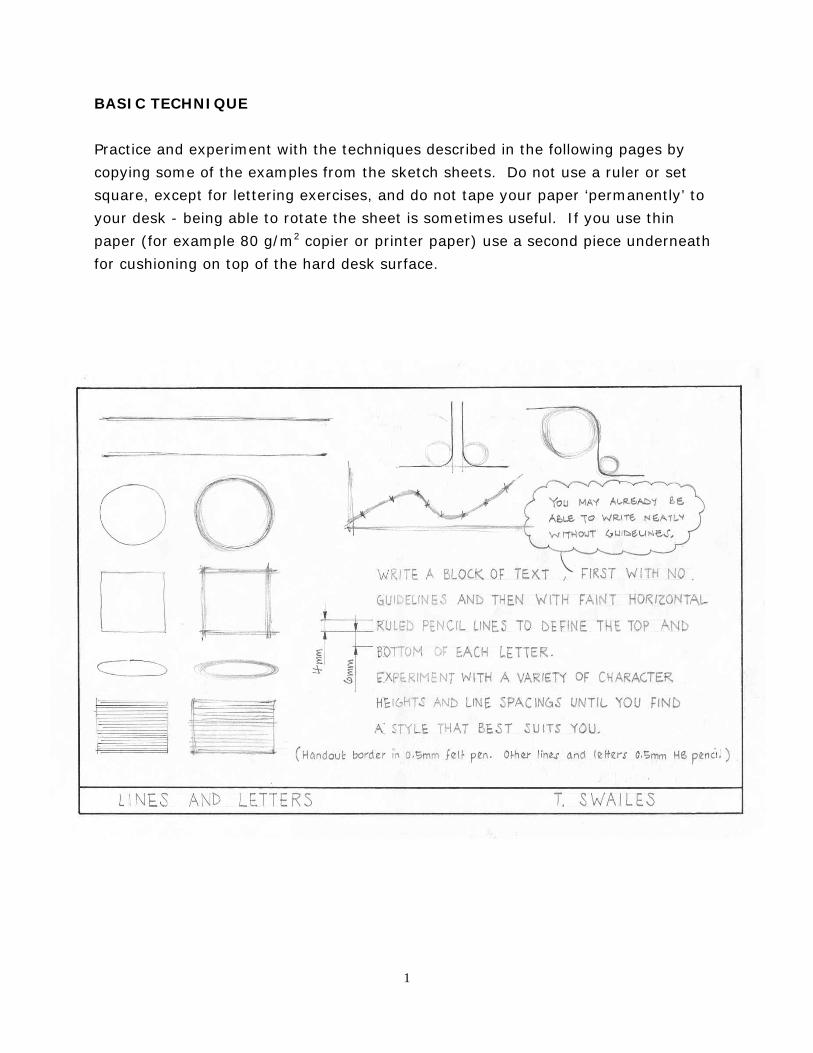
BASIC TECHNIQUE
Practice and experiment with the techniques described in the following pages by
copying some of the examples from the sketch sheets. Do not use a ruler or set
square, except for lettering exercises, and do not tape your paper ‘permanently’ to
your desk - being able to rotate the sheet is sometimes useful. If you use thin
paper (for example 80 g/m2 copier or printer paper) use a second piece underneath
for cushioning on top of the hard desk surface.
1
line quality
• Use a soft pencil (e.g. 0.5mm HB) to achieve a range of tone from light guidelines
that will not show on a photocopy to very dark grey lines that will photocopy
black. Provided that you are not too heavy handed, even the darkest lines can be
erased without leaving a grey smudge on the paper.
• Lines drawn quickly and confidently look better. A slow, shaky line looks as
though it does not know where it is going.
• Sharp lines tend to magnify errors. Fuzzy edged shapes usually ‘appear’ more as
they should.
straights
• Lightly mark points at each end of the intended line. Move your pencil between
the points a couple of times, with the pencil point just clear of the paper, to ‘teach
it the route’.
• Draw several guidelines between the points and then go over the ‘best line’ more
firmly.
curves
• Use parts of complete ellipses or circles as guidelines for the curve (see SHAPES).
• For complex curves, use a join the dots technique.
lettering
• Rule horizontal guidelines to define character height (i.e. top and bottom) and
line spacing.
• Judge character length and spacing of characters and words by eye unless the
lettering needs to be very large.
PRACTICE at every opportunity. Doodling is good practice for sketching.
2
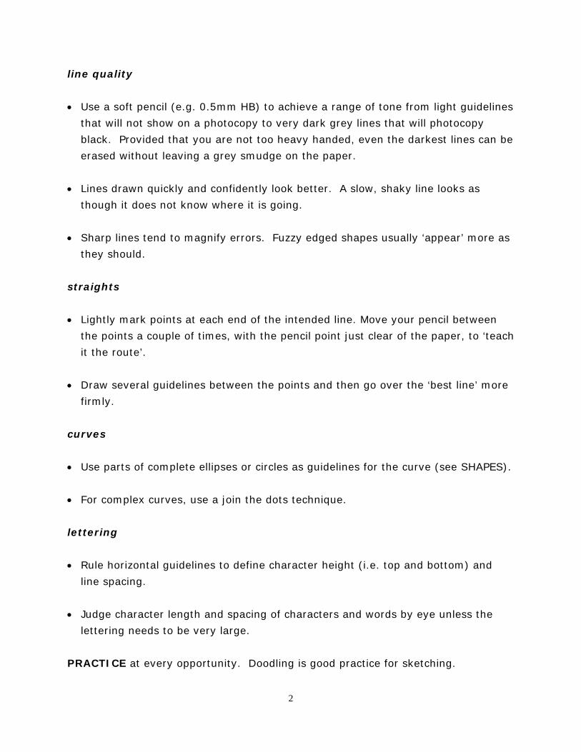
SHAPES
• Construct shapes using lines. Most of your lines will be guidelines so draw them
to be either nearly invisible or easily removable.
• Use diagonals to find the centre of a square or rectangle, either for sub-division
into smaller squares or rectangles or for the construction of circles or ellipses.
• The distance from the centre of a circle to its perimeter is constant (!). A circle
will touch an enclosing square at the centre of each of its edges.
• As a square squashes to a rectangle, so a circle squashes to an ellipse. The ellipse
is symmetrical about two axes and it still touches the squashed square at the
centre of its edges.
• A very close approximation of an ellipse can be constructed with circular curves of
two different radii.
3
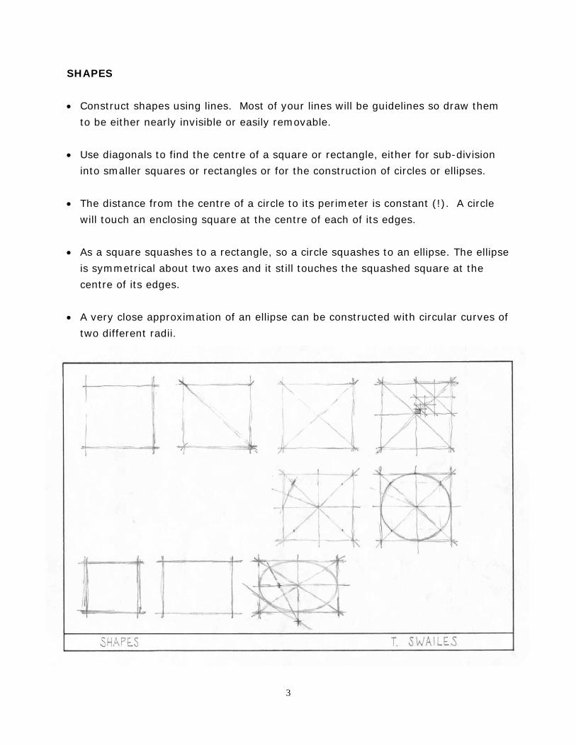
SOLIDS
• Construct solids from lines and complete shapes, using light guidelines for both
seen and unseen edges of the object.
• Go over or erase your light guidelines only when completely satisfied.
• A square approximates to a diamond when viewed at an angle. Draw a circular
bar by constructing ellipses on the ends of an enclosing square prism.
• Apply line shading parallel or perpendicular to the slope of a plane to indicate
form.
• A variety of techniques may be used to suggest a curved surface.
• Subtlety is lost in the photocopier or fax. so bear in mind how your sketch is to be
reproduced.
4
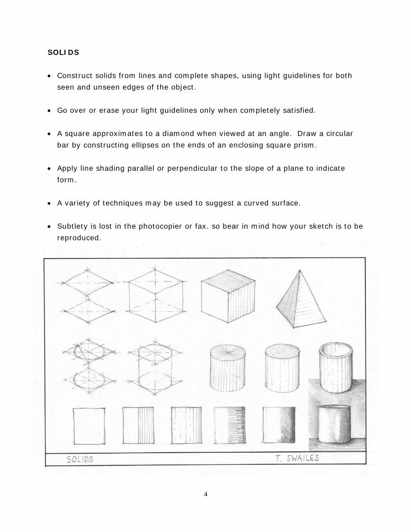
AXONOMETRIC VIEWS
An axonometric view can be built up from a true plan and elevations as shown in the
example below.
5
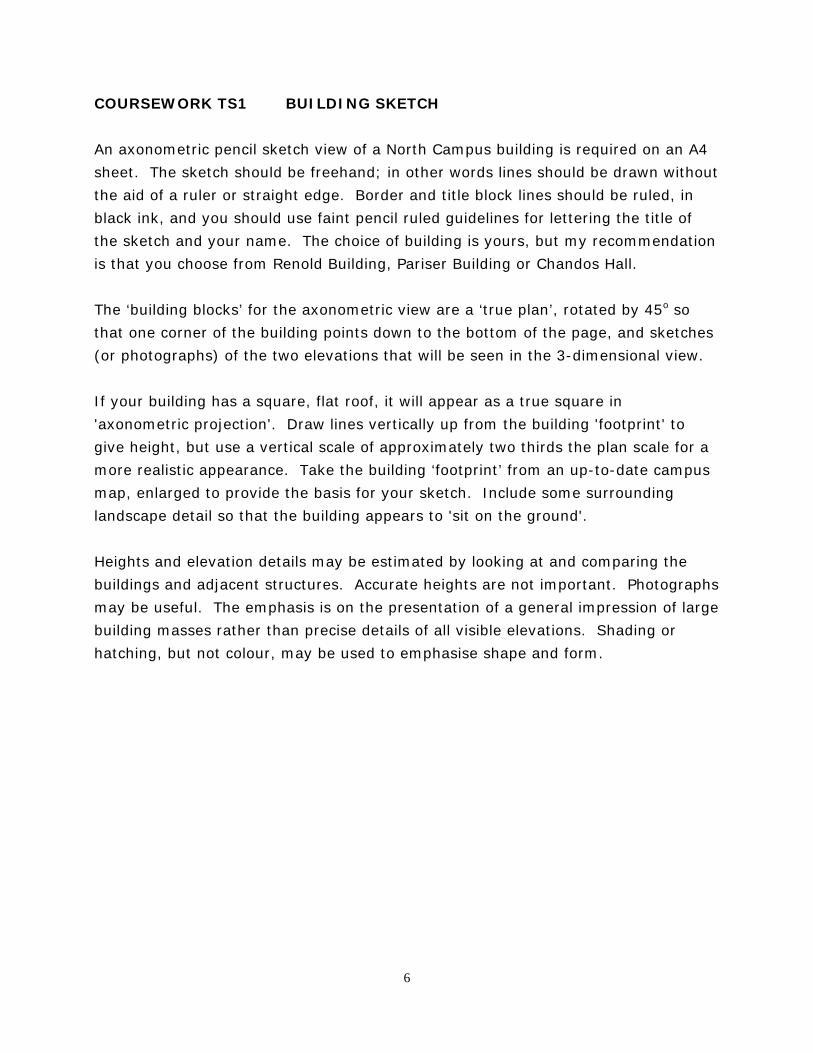
COURSEWORK TS1 BUILDING SKETCH
An axonometric pencil sketch view of a North Campus building is required on an A4
sheet. The sketch should be freehand; in other words lines should be drawn without
the aid of a ruler or straight edge. Border and title block lines should be ruled, in
black ink, and you should use faint pencil ruled guidelines for lettering the title of
the sketch and your name. The choice of building is yours, but my recommendation
is that you choose from Renold Building, Pariser Building or Chandos Hall.
The ‘building blocks’ for the axonometric view are a ‘true plan’, rotated by 45o so
that one corner of the building points down to the bottom of the page, and sketches
(or photographs) of the two elevations that will be seen in the 3-dimensional view.
If your building has a square, flat roof, it will appear as a true square in
'axonometric projection'. Draw lines vertically up from the building 'footprint' to
give height, but use a vertical scale of approximately two thirds the plan scale for a
more realistic appearance. Take the building ‘footprint’ from an up-to-date campus
map, enlarged to provide the basis for your sketch. Include some surrounding
landscape detail so that the building appears to 'sit on the ground'.
Heights and elevation details may be estimated by looking at and comparing the
buildings and adjacent structures. Accurate heights are not important. Photographs
may be useful. The emphasis is on the presentation of a general impression of large
building masses rather than precise details of all visible elevations. Shading or
hatching, but not colour, may be used to emphasise shape and form.
6
30o
60o60o
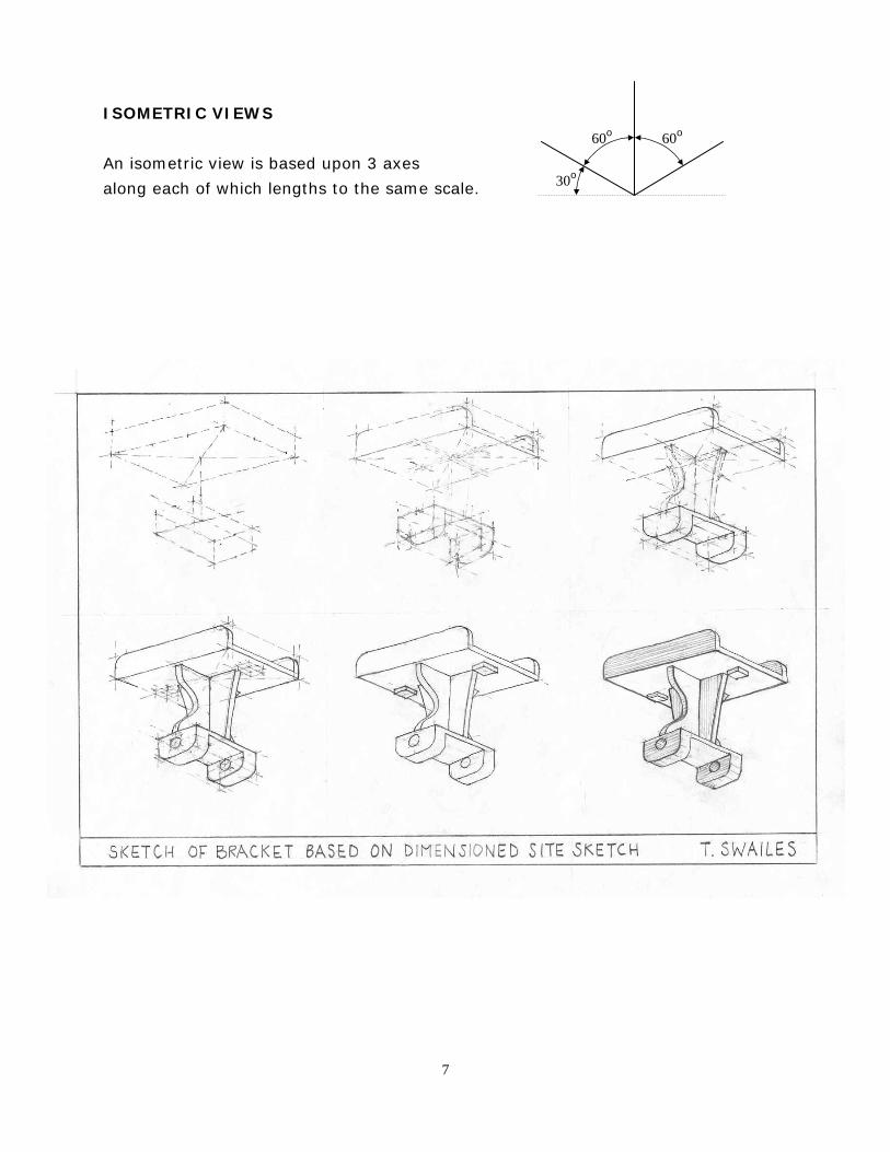
ISOMETRIC VIEWS
An isometric view is based upon 3 axes
along each of which lengths to the same scale.
7
COURSEWORK TS2 Object sketch
An isometric sketch is required. The example opposite shows how the finished
article (the sixth image) can be built up in stages.
• Study the object and decide on the position and angle of view that will show the
important features of the object most clearly.
• Look for symmetry.
Either
Assemble the object from simple solids, such as cubes or spheres, square,
rectangular, triangular, circular or elliptical prisms, pyramids or cones.
Or
Sculpt the object from simple solids.
• Look for common axes or alignments for the different parts of an object.
• Build up the object using faint guidelines for both seen and unseen edges.
• Be prepared to make adjustments by rubbing out and re-drawing faint guidelines,
several times if necessary, to ensure that proportions are correct and that the
sketch of the object will make best use of the available drawing area.
• Pause to make sure that you are satisfied with the result before committing dark
pencil lines or ink to paper.
• Simple shading may be used to emphasise form but is often not necessary.
• For most objects, use either an approximately axonometric view based on a plan
or an approximately isometric view for satisfactory results.
8
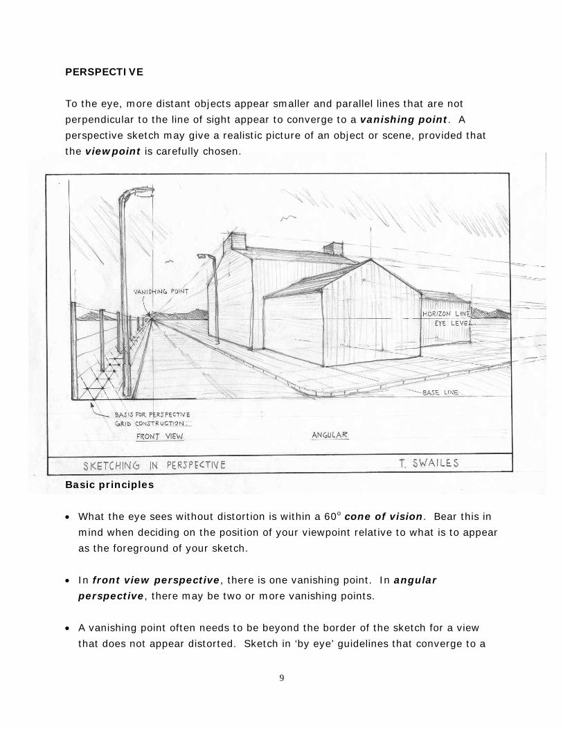
PERSPECTIVE
To the eye, more distant objects appear smaller and parallel lines that are not
perpendicular to the line of sight appear to converge to a vanishing point. A
perspective sketch may give a realistic picture of an object or scene, provided that
the viewpoint is carefully chosen.
Basic principles
• What the eye sees without distortion is within a 60o cone of vision. Bear this in
mind when deciding on the position of your viewpoint relative to what is to appear
as the foreground of your sketch.
• In front view perspective, there is one vanishing point. In angular
perspective, there may be two or more vanishing points.
• A vanishing point often needs to be beyond the border of the sketch for a view
that does not appear distorted. Sketch in ‘by eye’ guidelines that converge to a
9
common vanishing point outside the drawing area - the exact location of remote
vanishing points is not necessary.
• A perspective grid can be used as an aid to drawing objects at the correct
relative distance and size to one another.
• Simple line shading can be used to indicate shape and form, with the amount of
detail shown reducing with distance.
The application of some of these principles is shown in the example sketch.
COURSEWORK TS3 Building Interior Perspective sketch
Draw a freehand perspective sketch of an interior. Construction and finished lines
should be drawn without the aid of a ruler. I suggest you choose one of the
following internal spaces and use A3 paper, rather than A4.
Pariser Building: B floor Hydraulics Laboratory or D floor computer room
Renold Building: C floor main circulation space or northern entrance hall
(the stairs are good features to include)
If you find a different internal space more convenient or more interesting, that is
fine. A large or long room is needed, with features in the foreground and middle
distance to give the sketch real depth. An individual room in a hall of residence or
‘bedsit’ would not be suitable.
10
COURSEWORK TS4 Joint Detail sketch • An isometric sketch view is required to show the details of a structural steelwork
connection in the Pariser Building, either the hydraulics laboratory or one of the heavy structures laboratories (see class list for allocation of details)
Choose a single viewpoint that best shows the different components of the
connection and how they fit together. • For this exercise I expect you to make neat 'working notes and sketches' in the
laboratory and from these prepare the finished sketch. This will test your skill in observation. These working notes and sketches should be submitted along with the finished sketch. Put your name on each sheet submitted.
• The isometric sketch view should be done freehand (without a ruler) in pencil. • Once you have completed the sketch, it should be scanned, pasted into Microsoft
Word and labelled. On the next page I have provided a ‘before and after’ example. You should add a border and title block in Word too. Either 'portrait' or 'landscape' format is acceptable.
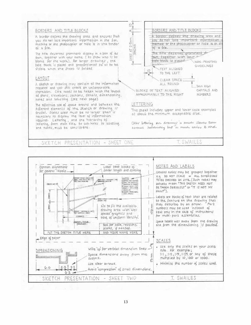
• Take care with the arrangement (position and alignment) of labels. See the two
sketch sheets on presentation on page 13 of this handout. • Typical labels may include, for example:
Universal Beam Universal Column Rolled Steel Channel Rolled Steel Angle Welded stiffener plate End plate Bolts (do not label individual bolts; positions may be shown schematically) Crane Rail Concrete Encasement Concrete Blockwork Roof Covering Floor
Window
11
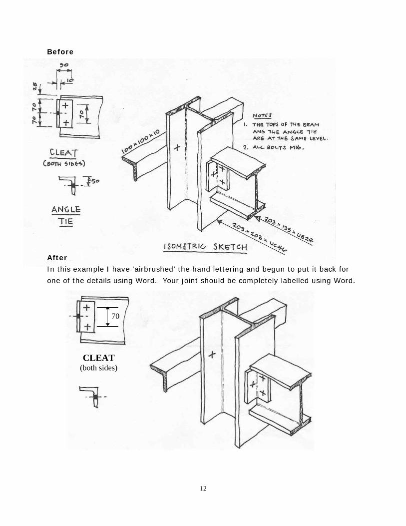
Before
After
In this example I have ‘airbrushed’ the hand lettering and begun to put it back for
one of the details using Word. Your joint should be completely labelled using Word.
70
CLEAT (both sides)
12
13
Tom Swailes
Pariser Building, Room B26
t 6-4611
Handout issue week 1, February 2006
14
Top Related