


Languages
Pages
Legal


ASGRO® Fracture Mechanics and Fatigue Crack Growth Analysis Software
NASA JSC Team Royce Forman
Dr. V. Shivakumar Dr. Sambi Mettu Joachim Beek
Leonard Williams Feng Yeh
Southwest Research Institute Team Dr. Craig McClung
Joe Cardinal
Source of Acquisition NASA Johnson Space Center
o
https://ntrs.nasa.gov/search.jsp?R=20100042296 2018-05-25T22:06:21+00:00Z

[ ,..-
NA
SG
RO
.

(f)'-
C
_.
CO
:J
o -
_.
C
'<
CD
><~Cl.
()~»
;::+
CD
::::
; . ~
--....
.....
_.
:J
CD
en o ()
I ~
o
o o :::l en
CD
.c
c: CD
::l n CD
en o -fit
II
.., D) n ... c: .., CD
gl NASA Fracture Control " i Requirements
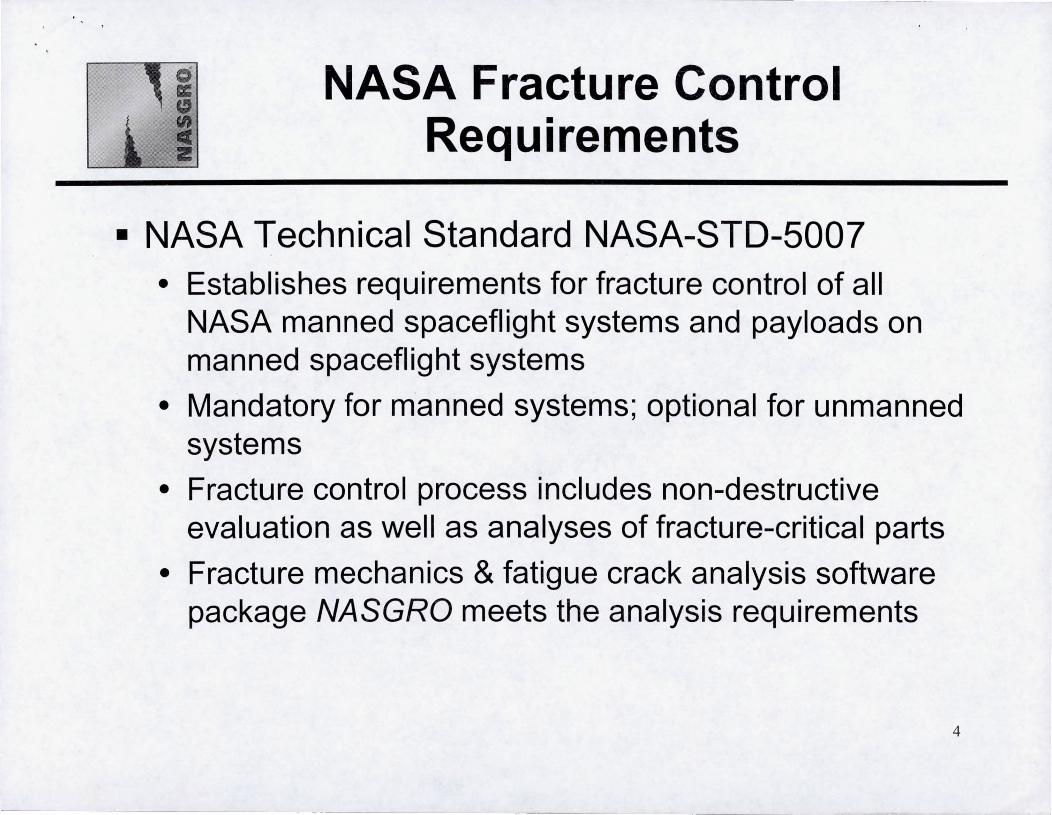
• NASA Technical Standard NASA-STO-5007 • Establishes requirements for fracture control of all
NASA manned spaceflight systems and payloads on manned spaceflight systems
• Mandatory for m"anned systems; optional for unmanned systems
• Fracture control process includes non-destructive evaluation as well as analyses of fracture-critical parts
• Fracture mechanics & fatigue crack analysis software package NASGRO meets the analysis requirements
4

($
II NASGRO® Reduces Risk c ii!
• Fracture mechanics & fatigue crack analysis software • Provides optimal design of fracture-resistant structures
¢ Determines safe stresses for a specified lifetime
• Provides specification of fracture control plans at the design stage ¢ Determines safe lifetime for a specified design
¢ Determines required inspection intervals (if any) to maintain safety
• If damage is discovered ... ¢ Determines safe remaining life (if any)
¢ Determines required inspection intervals (if any) to maintain safety
• Accurately simulates crack growth and failure in real structures ¢ Calculate fatigue crack growth rate and remaining life
¢ Calculate conditions (loads, crack sizes) that cause failure
-------------------------
5

NA
SG
RO
.
z l>
en
C)
;:tJ o @)
c:
en CD - ::l en _.
C.
CD z l>
en
l>

o II:
" NASGRO® Components:
Crack growth module ~ z
• Calculate fatigue crack growth or component life, critical crack sizes, or stress intensity factors for a library of 50+ different crack configurations
• Multiple crack growth equations
• Elastic-plastic crack growth analysis
_.DI25J Fie Options Tools ~
l' Ell 5electGe"""",YrlL' ~Mote''''1 ~ oer.,.specb-"'ITI .outputooik,n.lll Computotionsoodoulputl
I Co<"", Dock ,::J J CC02 . ot 011 •• 1 hole i1 pial. :::J
Thicknest. t ~ Wdh.W
J1s8 Hole diomete!.O 1501 Hole cb-to-edge di.c B
J1.99 Poitson tabo, nu
10 3
IrlbaIftawsi2e. a 1.031 h~tialtJ!c
r;:r
Inlial flow option r. lJ~entr.Y
r NASA SId NOE
ess FI fot context-sensitive~, F2 for general help
CC02 p
t t t t t t $0 + wt
~~.~ ~ S.= i5t p
M - +S, .. t +' +' +'
Save ptCtUfe to fe 1
JlEFM ~~)5:39!OI 4
§:tMiI.S3m$@.·"".'iiiBftfUE 1iJ-f1!J~jL.litf+ ~ ~"= l~rgL~ fill! {'v~ loos Ht'<f)
y Send~ to Ell SelectGeomeIlyl1L Cho<. . .oulputop!ions fl Computotionsoodoutput I
~4Q4 U r Do ........ 'UOS 101 CC02 t" q,.,,, .. Data point dt.Mnp to text t~e CGM r .. PostSCtiptfie GIF Iie PNGr.. ..:I
.oK I CMcel I
FATI GUE CRACK GRovrn ANALYSI S
i/l f\Ti11lllm..-i
u. S. Computed output for "Iest.in"
..JgJ25J
1.6 rl------------~ PROBLEM TIT;, 1.4 j, ~
C ~1 .2 R~~~~ ~~OVtl ~ 1 • qt. enOB 1 Equeti on/TaJ ~ . t ~ 0 6 J GEOI1ETIl.Y (j ' I 0.4 ~ MODEL, CC02" 0 .2 ~ •. ~ . f'IotV. N '....~' . ~PIot . .. . 1 '._ I ~ . O~· -~ / .
1I'".,~St~ _ ' ' . . . •• Wlndow l ~ 8 p .os ". "ocklenghjlgament - 93. 1B%(~) ! 1 5 :~ 08Ap r2~. ~ ~ ~Ycle~ ~ ~ ~ ~ .., ..,
to . t
7

($ a:
" en NASGRO® Components:
• z Material property module
• Store, retrieve, and curve-fit fatigue crack growth and fracture data
• NASA database: • 476 different metallic materials • 3000 sets of fatigue crack growth data • 6000 fracture toughness data points • Statistically-derived crack growth equations for all materials
• Users can create their own database ~..,JtI!l!l 1\ilrtl!!!l1 _Iolx l
Fie Optlons T ods Help
B3 Select Gecmelly IL Choo:eMate<i.oll~ oe/;,.speclIumfo ollputopliomi fl Computotiomondoulputi ·'----l f MotOli.olPIOP.rtysol 1 --~" --.----~ ----~----"'~. ~ r Non Irtefacbon Select data souce----, Avaeb/e dalctl ""oct:. data fOlm¥s J (' 80mg ConsL Do.Uf. fr. NASGRO 1Ml0li.0l1ie r. NASGRO _ con~"" r Hlloble
1 ("J GeneraizedWiIenbofg II r Usef rMterial tie ! r ES):)NLA t.-Q:~.!IIit.mt~;.'l;rt~I'''... r 1,P lJ.i:tle ~I~ dt: r · ChongWllerbag ! r New dat, i r \II""" ~"",,,,, _"1_ r AP toOl'); dll'<W' ~Str~Yiefd I •
r" comlI ... ..-J Cotegllly. \riot) l000900JSERIESAl :.:oJ Showl..... Enl .. IO
r. Consl ... [NASA) GIIlt.\> il2) 2OOO ... ies :.:oJ Add to I.ves
! r V.llable [ESA) AIoy; ilGC) 212H851 AI :.:oJ HeatiPfoo!I11A81) FUSr<;U; lA;Roomle<np :.:oJ
Mot .. i.oI p<opertie<- IM2GC11A81j UTS YIOid Kl. KlcAI<. 8. ~eg:o.oo-~~~~r-r-O.0015 Clack glowth p~ametets: equation con$la'ts C II !'----q OK1
Ilsf.B" ~ 10.5 ro.s-ro:n-
[
h1llial defeci choice j r USef·set p!.stle$$"/sh r. Dosed [-Ial9Je clackj
r Open (-.. """I) _._-----r. FtJ ItIl slnp-yteId modeIlOf ever)' schedtJe
.. u
i z
~
0.01
0001
00001
le{D5
I HIE
1..007
le-(03
l e·OO9
COMPARISON OF FIT TO OTHER DATA (ENVIRONMENT. THICKNESS, RNAlUE) FOR M2GC11A81
Mall: 2124-1851 AI
Cond: 1851: Em,,: LA; Spec' e(T), Olien: L-T; Ffeq: UNK
o t.-t2GC11A8)INI R= 01 thk=05 ref 1
~·l.i lA"
8 M2GC11AOOl N3 R = 0.4 Ihk = 0 5 ref- 1
- FllforR= 0 1
10 100
Oeha K Iksl"sql10n)J
[
Computational ;peed choice
~Fa$tlun: s~modeIonIyuntiavg~$f. Thu Feb2616 432004
------,ITI"--------------------------~------~
,press Ftf(;context--seoslivehei>, F2 for-oenelal~ LEFMUS Modified . 17 :08:5~ ~ 8

II Typical NASGRO® analysis: en ,.=1 Crack growth or component life calculation
• Problem: • Actual crack or flaw is reported in component
• Hypothetical flaw: assume worst-case scenario based on applied loading, component geometry, and crack location
• Analysis input: • Crack and component geometry
• Component material
• Load type and spectrum
• Analysis results: • Fatigue crack growth rate and remaining life
• Conditions (loads, crack sizes) that cause failure
• Safe stresses to attain a specified lifetime
• Component inspection intervals for safe operation
9
~ ~-
I NASGRO Sample Application: I " Orbiter feedline flowliner crack analysis 2:
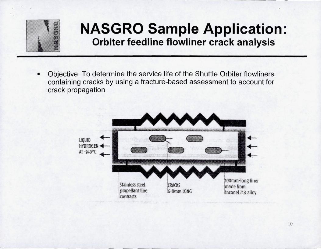
• Objective: To determine the service life of the Shuttle Orbiter flowliners containing cracks by using a fracture-based assessment to account for crack propagation
"-_._-- . --- _._--
UQUID +HYDROGEN .-AT -2400( ~
steel pro-petlant line contram
++--1-:-
10

= NASGRO Sample Application: en =1 Orbiter feedline flowliner crack analysis
• Problem: Flowliner crack geometry not easily represented by any of 50+ standard cracks in NASGRO crack library 3.5"
1.0"
So
H=0.75"
~
11

•
es a:
" en C 2
NASGRO Sample Application: Orbiter feedline flowliner crack analysis
: Oraw segments ROOEJ
Solution: Use NASGRO's Boundary Element Analysis module for its
• CAD-like drawing tools to custombuild crack model
• Computational core to calculate crack driving force K
!2l 1 ~[ml llllra l §llt l -I ;l l ~ 101···1 -I t H 11+H ~ tal@I€t1 'T~page 0, ... Segmer<. I p'oo. I segmert.l Zone._ Bourod¥;.. 1 H .... IlooOOg I Pnt I.OJId< I Gen, Docl<o I Spec, C,acl<. 1 101_1 c.Ic,/E><ec, I O'-"P<A I
, 3.9
'65
'66
-1,2
~:mm;ttl.4_ Dehne Zone;. Replot Change Scale I Undo Seg Undo Be I COORD [
Place ClJTSOf on ~ t~ get IlfOflnation
'58
, 4 ,4
e:;:ru- inch
4
12
~.~.----. ---_.
I NASGRO Sample Application: I II Orbiter feed line flowliner crack analysis
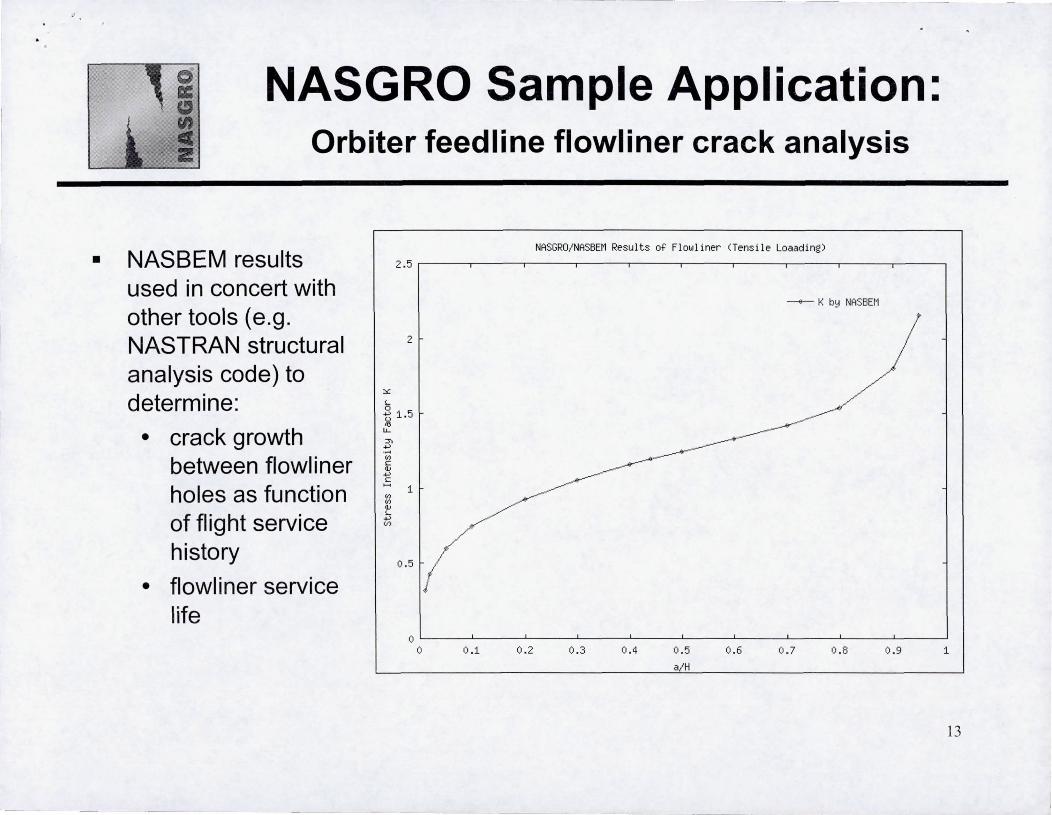
• NASBEM results used in concert with other tools (e.g. NASTRAN structural analysis code) to determine:
• crack growth between flowliner holes as function of flight service history
• flowliner service life
2 .5
2
::.: L
.3 1.5 tl
'" u.. ::r. ....,
.~
'" c
NASGRO/ NASBEr1 Resu 1 t s of Fl ow 1 i ner CT ens i 1 e Loaad i ng)
--.-- K b~ NASBEM
~ 1[ ~
~O. 5 f(
/
o !L-____ ~ ______ ~ ______ ~ ______ _L ______ _L ______ ~ ______ ~ ______ ~ ______ ~ ____ ~
o 0 .1 0 .2 0 .3 0 .4 0 .5 0 .6 0 . 7 0 .8 0 .9 1
a/H
13

~ -~ - ~-----=
o II:
" I 2
Summary and Challenges for the Future
• NASGRO® reduces the risk of fracture
• NASGRO is used extensively around the world • Standard code for analysis of space hardware for NASA and its
international partners
• Supported and used by 000, FAA, and private industry in aircraft, rotorcraft, turbine engines, and many others
• Spaceflight systems for future space missions will use innovative materials and methods of construction • New materials will require testing and characterisation for their
properties for use in fracture analyses
• New systems, components, configurations, and manufacturing techniques will need to be certified for flight
---- --~-
14
Top Related