


Languages
Pages
Legal


FOWLER CHAPTER 8LECTURE 8 ALTERNATING CURRENT AND VOLTAGE

CHAPTER 8 AC AND VOLTAGE P.201
FOR A DC WAVEFORM IN A SIMPLE CIRCUIT THE OUPUT IS ALWAYS CONSTANT, EXCEPT WHENTHE CIRCUIT IS SWITCHED ON/OFF. DC WAVEFORMS CAN BE + OR - BUT NEVER BOTH.
V
t
+-

TYPES OF AC WAVEFORMS
SINUSOIDAL
MOST COMMONLY USED INDIGITAL ELECTRONICS
SAWTOOTH( TV,RADAR)

CYCLE P.203: ONE WAVEFORM THAT DOES NOT REPEAT ITSELF
½ CYCLE
PERIOD (T) : TIME TO COMPLETE ONE CYCLE.( IN THIS CASE .25 SECONDS)
.25 S
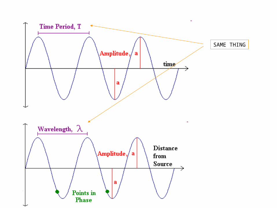
SAME THING


FREQUENCY( f ) : # OF CYCLES/SECOND
Time (sec) FOR THIS WAVEFORM f = 1 CYCLES/SEC
HERTZ: UNIT OF FREQUENCY . FOR THE ABOVE WAVEFORM f = 1 Hz f =1/T OR f =1/λ
AMPLITUDE: (a) HEIGTH OF THEWAVEFORM.

=1/T = 1/20ms = 1/.002 = 500Hz
EXAMPLE: FIND THE FREQUENCY FOR THE WAVE FORM BELOW.

PEAK VP : MAX. VALUE OF WAVEFORM.
CAN BE EITHER + OR-
M/U#38 3:30-12:40
SINCE WAVEFORMS ARE NOT CONTINIOUS ATALL TIMES THE AVERAGE VALUE IS USED.
VAV =AVERAGE VALVEVAV =0.637VP
VP = 1.57VAV}USEFUL IN AC/DC CIRCUITS
PPP VV 2
http://www.youtube.com/watch?v=7QCxbwzikFk

RMS( ROOT-MEAN-SQUARE)
WHAT IS THAT? 1. WAVE FORM IS DIVIDED UP INTO SMALL INTERVALS. 2. EACH INTERVAL IS SQUARDED. 3. MEAN (AVERAGE) OF SQUARED VALUE IS FOUND. 4. SQUARE ROOT OF THE MEAN IS CALCULATED.\

RMS value is an equivalent DC value which tells you how many volts or amps of DC that a time-varying sinusoidal waveform is equal to in terms of its ability to produce the same power. For example, If you have mains supply of 240Vac and is assumed an effective value of “240 Volts RMS”. This means then that the sinusoidal RMS voltage from the wall sockets of a home is capable of producing the same average positive power as 240 volts of steady DC voltage as shown below.

rms voltage = 0.707 peak voltage rms voltage = 1.11 average voltage
peak voltage = 1.414 rms voltage peak voltage = 1.57 average voltage
average voltage = 0.637 peak voltage average voltage = 0.9 rms voltage

SINE WAVES
REVIEW: WHEN A CONDUCTOR MOVES THRU A MAGNETIC FLUX, A VOLAGE AND CURRENT ARE INDUCTED IN THE CONDUCTOR.
THE AMOUNT OF INDUCED VOLTAGE IS A FUNCTION OF THE AMOUNT OF FLUX CUT BY THE CONDUCTOR
http://www.youtube.com/watch?v=P3kJd3MDeuk&list=UUOc3q8ChcDYyeyFROxLDhuw
Magnetic Induction in a Wire

AMOUNT OF FLUX CUT DEPENDS ON1. SPEED OF THE CONDUCTOR2. FLUX DENSITY 3. ANGLE THAT CONDUCTOR CROSSES THE MAGNETIC FILED.
SEE FIG. 8.8,P208
DIRECTION OF INDUCTED CURRENT DEPENDS ON1. DIRECTION CONDUCTOR IS MOVING.2. POLARITY OF THE MAGNETIC FIELD.

LEFT HAND RULE. P.209
http://www.youtube.com/watch?v=KUrMt6ic53o&list=UUOc3q8ChcDYyeyFROxLDhuwBuilding a Generator: size of induced current

YOU CAN GENERATING A SINE WAVE BY ROTATING A CONDUCTOR THRU A MAGNETIC FIELD.
PRODUCING SINE WAVES. P.209
Commutators: Basics on AC and DC Generation http://www.youtube.com/watch?v=ATFqX2Cl3-w&list=UUOc3q8ChcDYyeyFROxLDhuw&index=6

ONE ROTATION OF A CONDUCTOR THRU 4 POLES GENERATES TWO CYCLES OF VOLTAGE/CURRENT.
YOU TUBE:AC Motor Animation Video http://www.youtube.com/watch?v=Q4FlUP-kJe8
http://www.youtube.com/watch?v=P83Qa3Chb7I&list=UUOc3q8ChcDYyeyFROxLDhuw
Slip Rings and Brushes - Generators
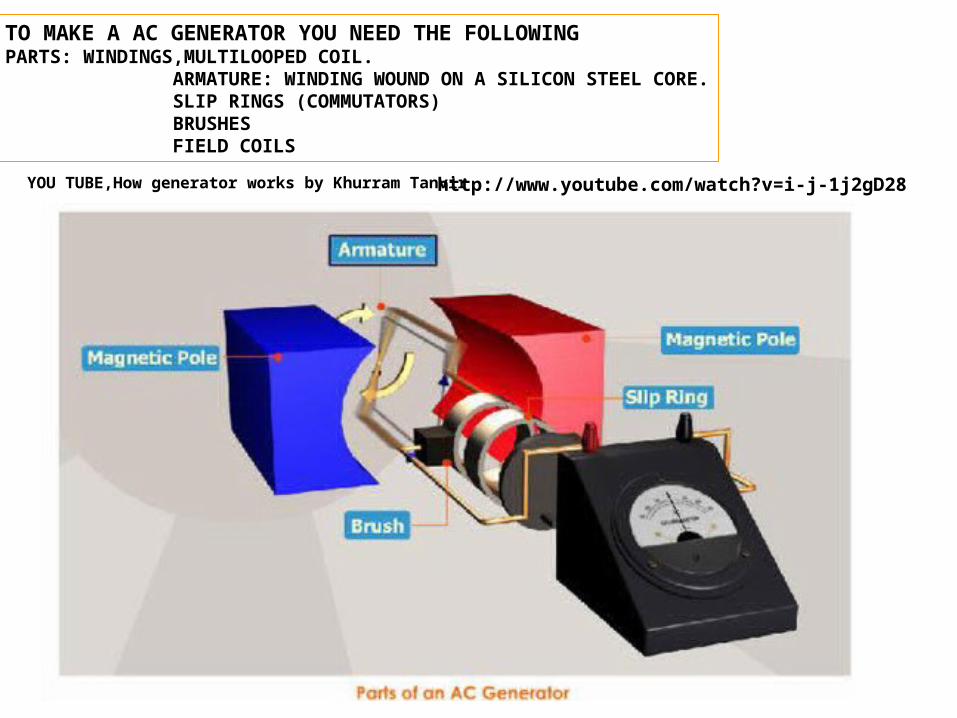
TO MAKE A AC GENERATOR YOU NEED THE FOLLOWINGPARTS: WINDINGS,MULTILOOPED COIL. ARMATURE: WINDING WOUND ON A SILICON STEEL CORE. SLIP RINGS (COMMUTATORS) BRUSHES FIELD COILS
YOU TUBE,How generator works by Khurram Tanvir http://www.youtube.com/watch?v=i-j-1j2gD28
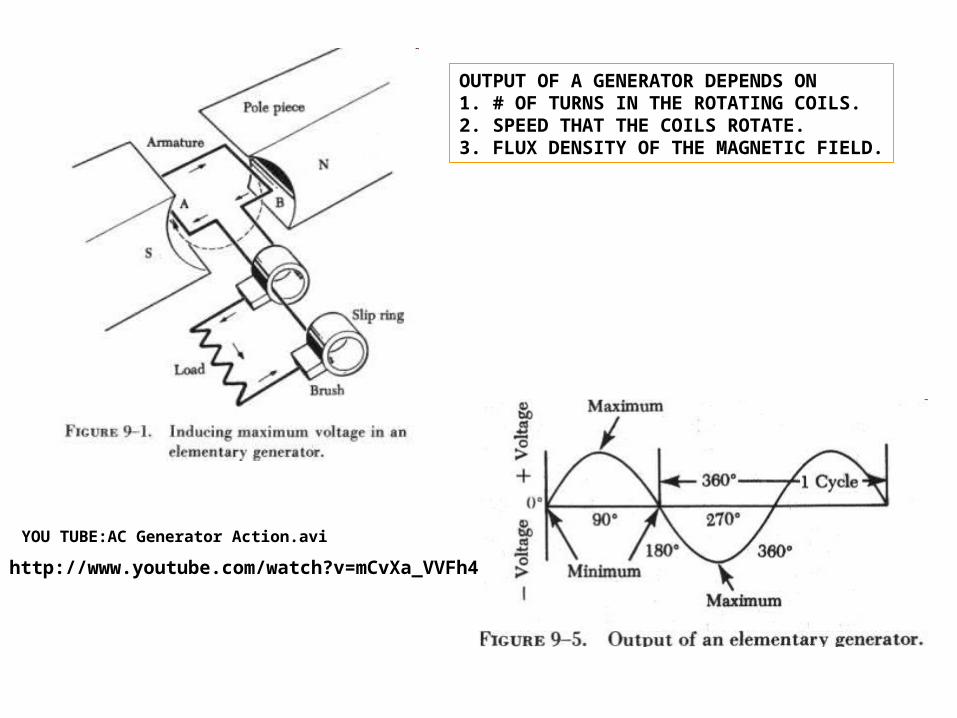
OUTPUT OF A GENERATOR DEPENDS ON1. # OF TURNS IN THE ROTATING COILS.2. SPEED THAT THE COILS ROTATE.3. FLUX DENSITY OF THE MAGNETIC FIELD.
YOU TUBE:AC Generator Action.avi
http://www.youtube.com/watch?v=mCvXa_VVFh4

YOU TUBE,Magnetism: Motors and Generators START AT 25SEC
GENERATOR FREQUENCY P.212FREQ. OUTPUT OF A GENERATOR DEPENDS ON1. # OF PAIRS OF MAGNETIC POLES.2. ROTATIONAL SPEED OF THE COILS.
FREQ. GEN.OUT =(R PER MINUTE)X(PAIRS OF POLES)/60
EXAMPLE:WHAT IS FREQ. OF 6 POLE GENERATOR ROTATING AT 1200 RPM?
The Frequency of an AC Generator www.wisc-online.com/ViewObject.aspx?ID=IAU14108
http://www.youtube.com/watch?v=d_aTC0iKO68
AC GENERATOR BUILT IN 1890
POLESOFNUMBERN
SPEEDROTATIONALRWHERE
HzscRN
f
120/12060
61200
60

The Mechanical Universe - 38 - Alternating Current,17:00-21:00 AC vs.DC
Advantages of A.C. over D.C. / Why generation is done in A.C.
1. AC CAN BE GENERATED AT HIGH VOLTAGES.2. HV AC GENERATORS ARE SIMPLER AND CHEAPER THEN DC GENERATORS.3. AC CAN BE STEPPED UP OR DOWN WITH TRANSFORMERS.
http://www.youtube.com/watch?v=7QCxbwzikFk

50Hz vs. 60Hz

Utility Frequencies in Use in 1897 in North America
Hz Description
140 Wood arc-lighting dynamo
133 Stanley-Kelly Company
125 General Electric single-phase
66.7 Stanley-Kelly company
62.5 General Electric "monocyclic"
60 Many manufacturers, becoming "increasingly common" in 1897
58.3 General Electric Lachine Rapids
40 General Electric
33 General Electric at Portland Oregon for rotary converters
27 Crocker-Wheeler for calcium carbide furnaces
25 Westinghouse Niagara Falls 2-phase - for operating motors
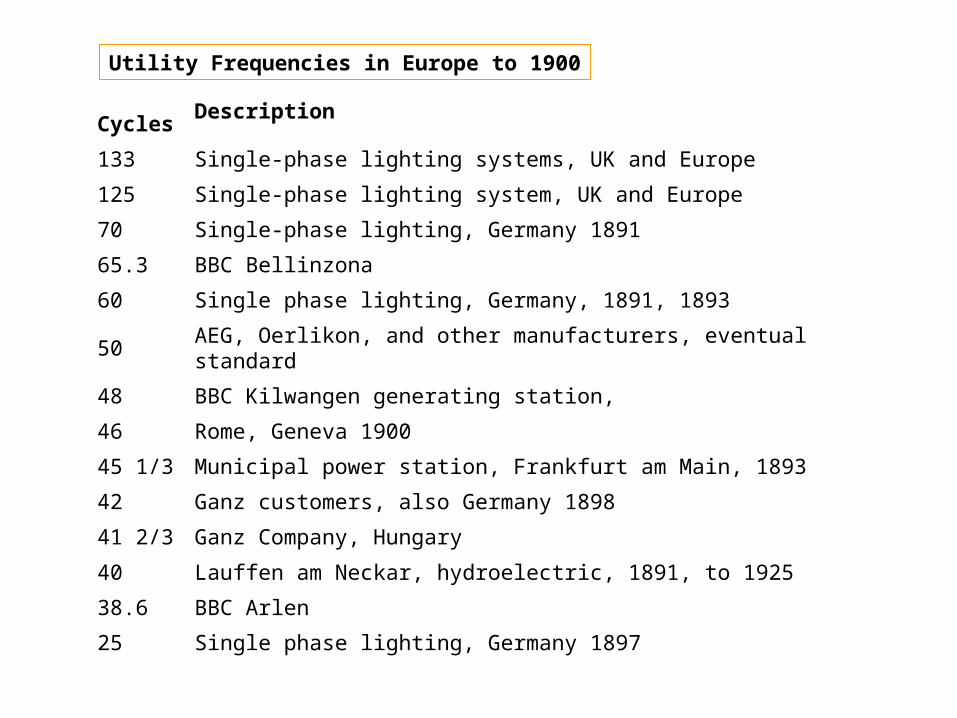
Utility Frequencies in Europe to 1900
CyclesDescription
133 Single-phase lighting systems, UK and Europe
125 Single-phase lighting system, UK and Europe
70 Single-phase lighting, Germany 1891
65.3 BBC Bellinzona
60 Single phase lighting, Germany, 1891, 1893
50 AEG, Oerlikon, and other manufacturers, eventual standard
48 BBC Kilwangen generating station,
46 Rome, Geneva 1900
45 1/3 Municipal power station, Frankfurt am Main, 1893
42 Ganz customers, also Germany 1898
41 2/3 Ganz Company, Hungary
40 Lauffen am Neckar, hydroelectric, 1891, to 1925
38.6 BBC Arlen
25 Single phase lighting, Germany 1897

3 PHASE AC P.213POWER PLANTS PRODUCE 3 PHASE AC. EACH PHASE IS SEPARATED BY 120°. P. 214

http://www.youtube.com/watch?v=fGPdPKMSpv83 Phase AC Motor Working Principle
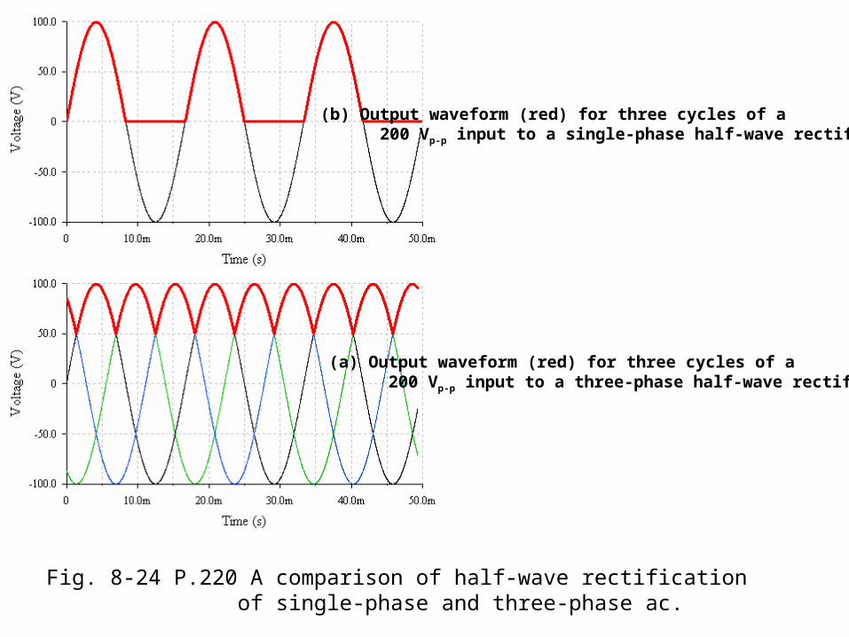
Fig. 8-24 P.220 A comparison of half-wave rectification of single-phase and three-phase ac.
(a) Output waveform (red) for three cycles of a 200 Vp-p input to a three-phase half-wave rectifier
(b) Output waveform (red) for three cycles of a 200 Vp-p input to a single-phase half-wave rectifier

(a) Output waveform of a full-wave three-phase rectifier with an input of 200 Vp-p.
(a) Output waveform of a full-wave single-phase rectifier with an input of 200 Vp-p.
Fig. 8-25 P.221 Comparison of full-wave rectification of three-phase and single-phase ac.

3 PHASES ARE CONNECTED SO THE LOAD CAN BE CARRIED ON 3 CONDUCTORS FROMTHE POWER PLANT TO THE USER.3 PHASES ARE CONNECTED IN EITHER DELTA OR WYE CONFIGURATION.
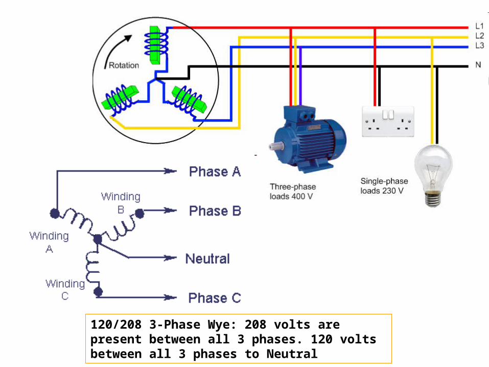
120/208 3-Phase Wye: 208 volts are present between all 3 phases. 120 volts between all 3 phases to Neutral

GROUND
NEUTRAL
LINE 1
LINE 2
LINE 3
PHASE 1 120 V
PHASE 2 120 V
PHASE 3 120 V
120 V
120 V
120 V 208 V
208 V
208 V
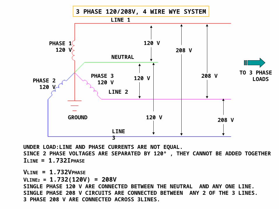
3 PHASE 120/208V, 4 WIRE WYE SYSTEM
TO 3 PHASE LOADS
UNDER LOAD:LINE AND PHASE CURRENTS ARE NOT EQUAL.SINCE 2 PHASE VOLTAGES ARE SEPARATED BY 120º , THEY CANNOT BE ADDED TOGETHERILINE = 1.732IPHASE
VLINE = 1.732VPHASE
VLINE2 = 1.732(120V) = 208VSINGLE PHASE 120 V ARE CONNECTED BETWEEN THE NEUTRAL AND ANY ONE LINE.SINGLE PHASE 208 V CIRCUITS ARE CONNECTED BETWEEN ANY 2 OF THE 3 LINES.3 PHASE 208 V ARE CONNECTED ACROSS 3LINES.


ADVANTAGES OF 3 PHASE (Φ) SYSTEMS.1.MORE EFFICENT USE OF COPPER.2 PROVIDES A MORE CONSTANT LOAD ON THE GENERATOR.3. MOTORS ARE LESS COMPLEX4. 2 OUT OF 3 PHASES ARE PROVIDING CURRENT AT ANY TIME.


VARIOUS 3 PHASE TRANSFORMERS

ELECTRIC CARS HYBRIDS AND PLUG IN HYBRIDS

CHARGING A ELECTRIC CAR USING MAGNETIC INDUCTION

INDUCTION COILS CHARGING A ELECTRIC CARS BATTERY PACK


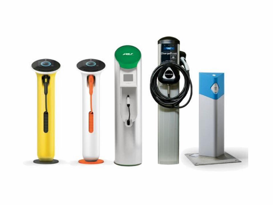
ONE OF THE MANY PRESENT DAY PLUG AND SOCKET FOR ELECTRIC CARS


Leviton Evr-Green Base Level 1 GFCI Guide Light Receptacle for Electric Vehicles

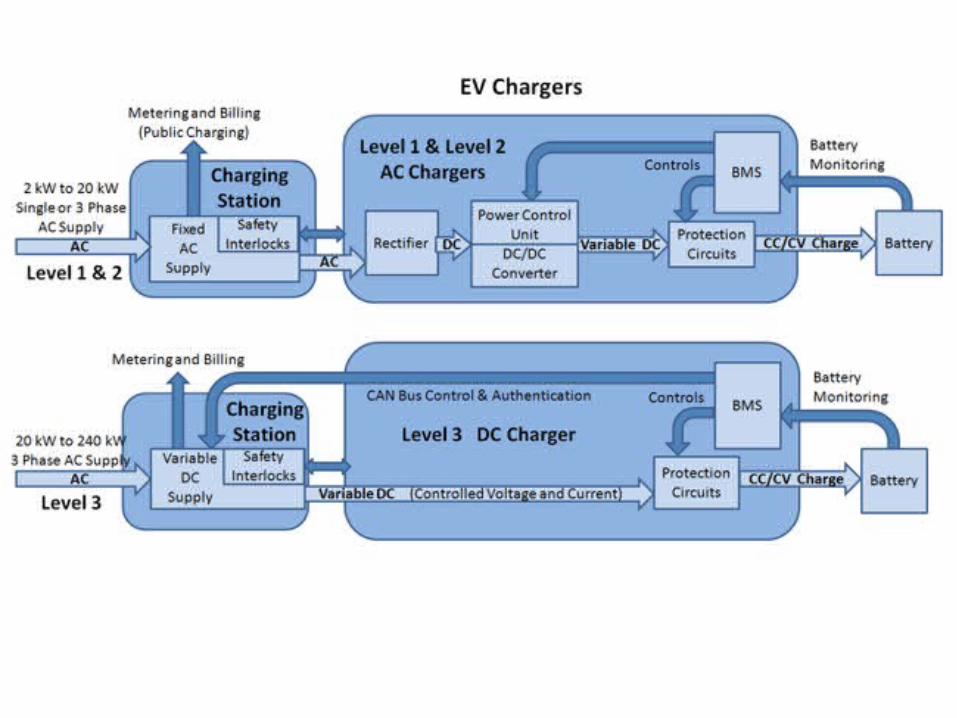
Charging time Power supply VoltageMax current
6–8 hours Single phase - 3,3 kW 230 VAC 16 A
2–3 hours Three phase - 10 kW 400 VAC 16 A
3–4 hours Single phase - 7 kW 230 VAC 32 A
1–2 hours Three phase - 24 kW 400 VAC 32 A
20–30 minutes
Three phase - 43 kW 400 VAC 63 A
20–30 minutes
Direct current - 50 kW
400 - 500 VDC
100 - 125 A
Battery swapping
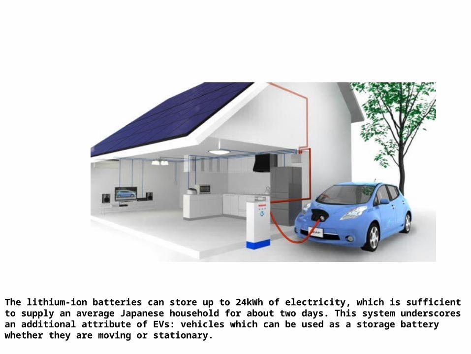
The lithium-ion batteries can store up to 24kWh of electricity, which is sufficient to supply an average Japanese household for about two days. This system underscores an additional attribute of EVs: vehicles which can be used as a storage battery whether they are moving or stationary.

Nissan Motor Co., Ltd. will launch the "LEAF to Home" power supply system, which can supply electricity from batteries onboard in Nissan LEAF electric vehicles (EV) to homes when used with the "EV Power Station" unit developed by Nichicon Corporation. "LEAF to Home" is an industry first backup power supply system that can transmit the electricity stored in the large-capacity batteries of Nissan LEAFs to a residential home.

This system helps to balance the electrical supply system, and can even lower a consumer's electricity bill. The LEAF to Home system will help encourage Nissan LEAF owners to charge their cars with electricity generated during the night, when demand is low, or sourced from solar panels. This assist in balancing energy needs by supplying electricity to the grid during daytime, when demand is highest. It can also be used as back-up power source in case of power outages and/or shortages.


Top Related