


Languages
Pages
Legal

FORWARD
AIR CONTROLLER
TACTICAL POCKET CHECKLIST REVISED APRIL 2001

FORWARD AIR CONTROLLER
TACTICAL POCKET CHECKLIST
The Distance Learning & Technologies Department (DLTD),
publishes and distributes this manual.
For additional copies:
Director, Marine Corps Institute Attn: Operations
Marine Corps Institute 912 Charles Poor Street SE
Washington Navy Yard DC 20391-5680
Intranet://intranet.mbw.usmc.mil http://www..mci.usmc.mil
1-(800) USMC-MCI
REVISED APRIL 2001
i
TABLE OF CONTENTS
SUBJECT PAGE Tactical Communication Communications Frequency Chart 1 USMC Fire Support Communication Nets 2 U.S. Aircraft Communication Equipment 3 U.S. Ground Forces Communications Equipment 4 Communications Brevity Terms for CAS Missions (Laser/IR/etc.) 5 Target Weather Information (TARWI) 6 Assault Support Assault Support Request Form 7 Assault Support Request Form Instructions for Completing 9 ZIPPO Briefing Guide 13 Landing Zone Brief 16 Basic Load Weight 17 Time Factors for Wave Planning/Recommended Landing Zone Diameter 18 Joint Tactical Airlift Request Form 19 Close Air Support Joint Tactical Air Strike Request (JTAR) 23 Joint Tactical Air Strike Request (JTAR) Instructions 25 CAS Check-in Brief Form/CAS Multi-Mission “9-Line” Form 31 Close Air Support (CAS) “The “9-Line” Brief Instructions 32 CAS Check-out Brief (BDA Report) 35 Laser Designation Zones 36 Hellfire Designator Exclusion Zone 37 Hellfire Designator Missile Surface Danger Zone (W/Laser) 38 Hellfire Missile Surface Danger Zone (W/O Laser) 39 LASER CAS OPERATIONS AN/PAQ-3 (MULE) Day Sight Operations Tactical Checklist 41 AN/PAQ-3 (MULE) Operations Checklist Night Sight Procedures 42 AC-130 Call-for-Fire (CFF) 43 NATO Information Briefing Formats/ NATO Fighter Check-In Briefing Worksheet 44 NATO Forward Air Controller to Attack Aircraft Briefing 45 NATO Close Air Support Multiple Mission Worksheet 46 Indirect Fire Support (Artillery/ Mortars/ Naval Surface Fires) Artillery/Mortar Call-For-Fire (CFF) 47 Message to Observer (MTO) /Basic SEAD Call-For-Fire (CFF) 48 Fire Support Scheduling Worksheet (x2) 49

ii
TABLE OF CONTENTS (Continued) SUBJECT PAGE Indirect Fire Support (Artillery/ Mortars/ Naval Surface Fires), (Continued) Target Card (1 of 2) 51 Record of Missions (2 of 2) 52 Characteristics of U.S. Artillery, Mortars, and Rockets 53 U.S. Artillery/Mortars Ammunition 54 Naval Gunfire Call-For-Fire (CFF) 55 Naval Gunfire Support Ships/ Naval Gunfire Ammunition 56
Aerial Reconnaissance and Electronic Warfare Joint Tactical Reconnaissance Surveillance Request Form 57 Joint Tactical Electronic Warfare Request Form 61 Joint Tactical Electronic Warfare Form Instructions 64 Capabilities of Equipment, Weapons and Ordnance U.S. Attack Fixed-Wing Aircraft 69 U.S. Attack Rotary-Wing Aircraft 71 U.S. Aircraft Navigation Equipment 72 Rapid Weaponeering 73 Ordnance Nomenclature 74 Ordnance Selection Guide 75 Ordnance “Quick” Reference Guide 79 Risk-Estimate Distances for Aircraft Delivered Ordnance (Combat only) 81 Threat Systems World Threat Anti-Air Defense Weapons Systems 83 Combat Vehicles and Armored Weapons Systems 84 Air Speed/Velocity Conversion Table 86 Aviation Staff Officer Information Aviation Estimate of Supportability 87 Appendix A Joint Air Operations Plan Format 89
1
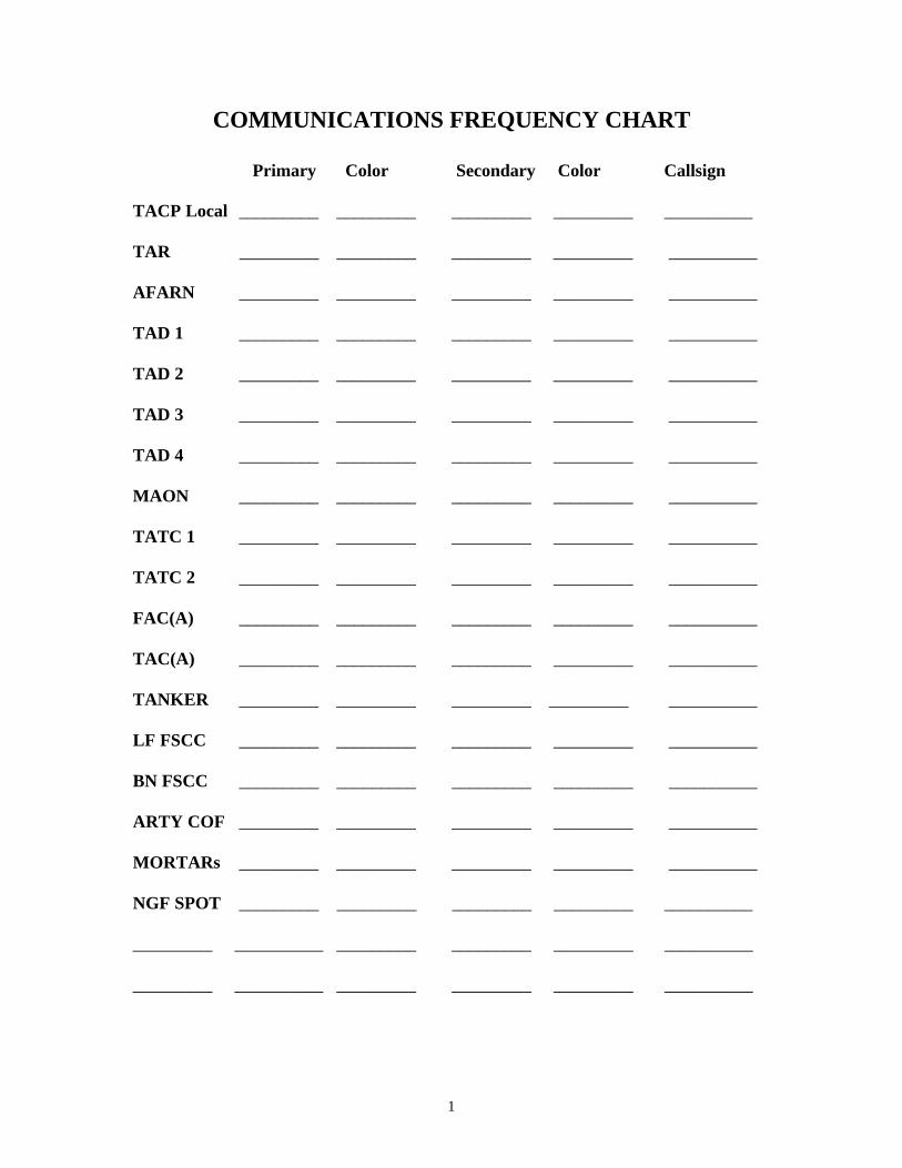
COMMUNICATIONS FREQUENCY CHART Primary Color Secondary Color Callsign TACP Local _________ _________ _________ _________ __________ TAR _________ _________ _________ _________ __________ AFARN _________ _________ _________ _________ __________ TAD 1 _________ _________ _________ _________ __________ TAD 2 _________ _________ _________ _________ __________ TAD 3 _________ _________ _________ _________ __________ TAD 4 _________ _________ _________ _________ __________ MAON _________ _________ _________ _________ __________ TATC 1 _________ _________ _________ _________ __________ TATC 2 _________ _________ _________ _________ __________ FAC(A) _________ _________ _________ _________ __________ TAC(A) _________ _________ _________ _________ __________ TANKER _________ _________ _________ _________ __________ LF FSCC _________ _________ _________ _________ __________ BN FSCC _________ _________ _________ _________ __________ ARTY COF _________ _________ _________ _________ __________ MORTARs _________ _________ _________ _________ __________ NGF SPOT _________ _________ _________ _________ __________ _________ __________ _________ _________ _________ __________ _________ __________ _________ _________ _________ __________
2
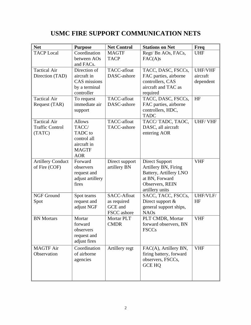
USMC FIRE SUPPORT COMMUNICATION NETS
Net Purpose Net Control Stations on Net Freq TACP Local Coordination
between AOs and FACs.
MAGTF TACP
Regt/ Bn AOs, FACs, FAC(A)s
UHF
Tactical Air Direction (TAD)
Direction of aircraft in CAS missions by a terminal controller
TACC-afloat DASC-ashore
TACC, DASC, FSCCs, FAC parties, airborne controllers, CAS aircraft and TAC as required
UHF/VHF aircraft dependent
Tactical Air Request (TAR)
To request immediate air support
TACC-afloat DASC-ashore
TACC, DASC, FSCCs, FAC parties, airborne controllers, HDC, TADC
HF
Tactical Air Traffic Control (TATC)
Allows TACC/ TADC to control all aircraft in MAGTF AOR
TACC-afloat TACC-ashore
TACC/ TADC, TAOC, DASC, all aircraft entering AOR
UHF/ VHF
Artillery Conduct of Fire (COF)
Forward observers request and adjust artillery fires
Direct support artillery BN
Direct Support Artillery BN, Firing Battery, Artillery LNO at BN, Forward Observers, REIN artillery units
VHF
NGF Ground Spot
Spot teams request and adjust NGF
SACC-Afloat as required GCE and FSCC ashore
SACC, TACC, FSCCs, Direct support & general support ships, NAOs
UHF/VLF/HF
BN Mortars Mortar forward observers request and adjust fires
Mortar PLT CMDR
PLT CMDR, Mortar forward observers, BN FSCCs
VHF
MAGTF Air Observation
Coordination of airborne agencies
Artillery regt FAC(A), Artillery BN, firing battery, forward observers, FSCCs, GCE HQ
VHF
3
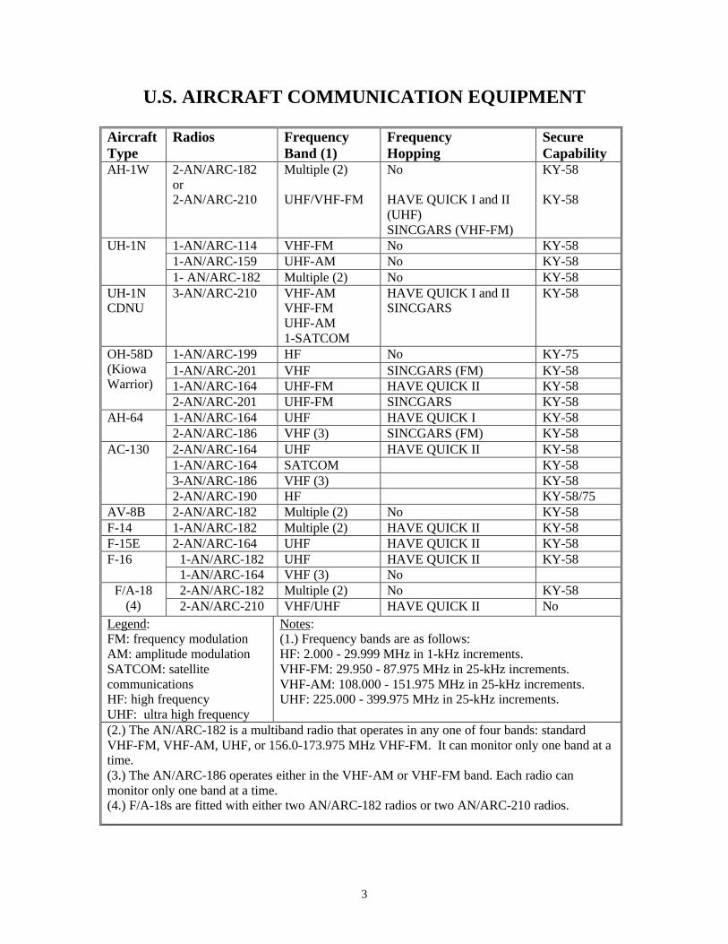
U.S. AIRCRAFT COMMUNICATION EQUIPMENT
Aircraft Type
Radios Frequency Band (1)
Frequency Hopping
Secure Capability
AH-1W 2-AN/ARC-182 or 2-AN/ARC-210
Multiple (2) UHF/VHF-FM
No HAVE QUICK I and II (UHF) SINCGARS (VHF-FM)
KY-58 KY-58
1-AN/ARC-114 VHF-FM No KY-58 1-AN/ARC-159 UHF-AM No KY-58
UH-1N
1- AN/ARC-182 Multiple (2) No KY-58 UH-1N CDNU
3-AN/ARC-210 VHF-AM VHF-FM UHF-AM 1-SATCOM
HAVE QUICK I and II SINCGARS
KY-58
1-AN/ARC-199 HF No KY-75 1-AN/ARC-201 VHF SINCGARS (FM) KY-58 1-AN/ARC-164 UHF-FM HAVE QUICK II KY-58
OH-58D (Kiowa Warrior) 2-AN/ARC-201 UHF-FM SINCGARS KY-58
1-AN/ARC-164 UHF HAVE QUICK I KY-58 AH-64 2-AN/ARC-186 VHF (3) SINCGARS (FM) KY-58 2-AN/ARC-164 UHF HAVE QUICK II KY-58 1-AN/ARC-164 SATCOM KY-58 3-AN/ARC-186 VHF (3) KY-58
AC-130
2-AN/ARC-190 HF KY-58/75 AV-8B 2-AN/ARC-182 Multiple (2) No KY-58 F-14 1-AN/ARC-182 Multiple (2) HAVE QUICK II KY-58 F-15E 2-AN/ARC-164 UHF HAVE QUICK II KY-58
1-AN/ARC-182 UHF HAVE QUICK II KY-58 F-16 1-AN/ARC-164 VHF (3) No 2-AN/ARC-182 Multiple (2) No KY-58 F/A-18
(4) 2-AN/ARC-210 VHF/UHF HAVE QUICK II No Legend: FM: frequency modulation AM: amplitude modulation SATCOM: satellite communications HF: high frequency UHF: ultra high frequency
Notes: (1.) Frequency bands are as follows: HF: 2.000 - 29.999 MHz in 1-kHz increments. VHF-FM: 29.950 - 87.975 MHz in 25-kHz increments. VHF-AM: 108.000 - 151.975 MHz in 25-kHz increments. UHF: 225.000 - 399.975 MHz in 25-kHz increments.
(2.) The AN/ARC-182 is a multiband radio that operates in any one of four bands: standard VHF-FM, VHF-AM, UHF, or 156.0-173.975 MHz VHF-FM. It can monitor only one band at a time. (3.) The AN/ARC-186 operates either in the VHF-AM or VHF-FM band. Each radio can monitor only one band at a time. (4.) F/A-18s are fitted with either two AN/ARC-182 radios or two AN/ARC-210 radios.
4
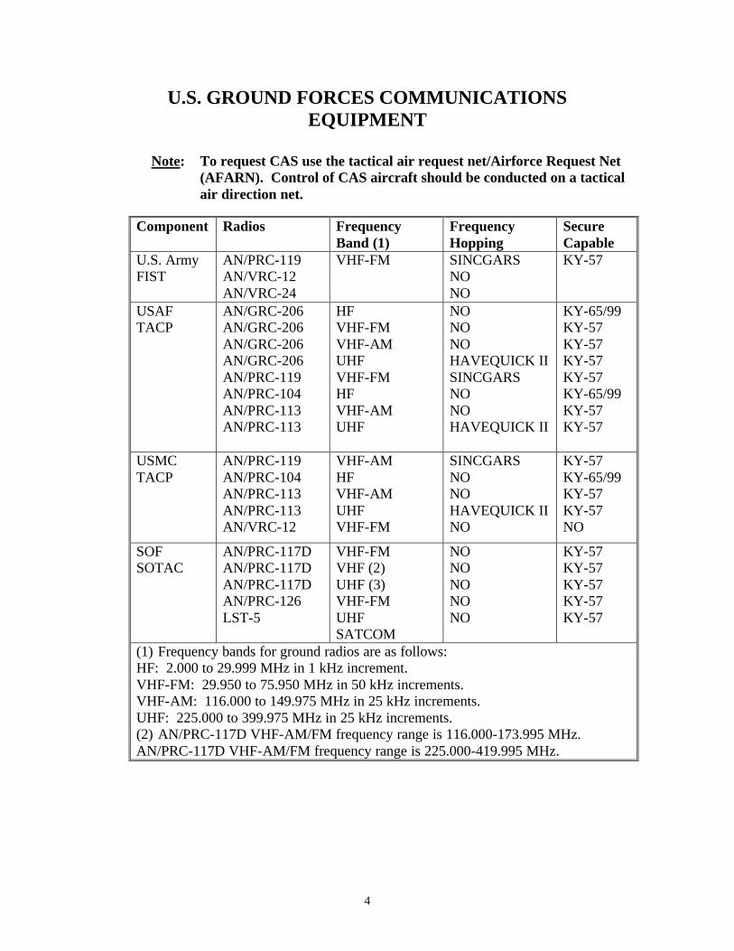
U.S. GROUND FORCES COMMUNICATIONS EQUIPMENT
Note: To request CAS use the tactical air request net/Airforce Request Net
(AFARN). Control of CAS aircraft should be conducted on a tactical air direction net.
Component Radios Frequency Band (1)
Frequency Hopping
Secure Capable
U.S. Army FIST
AN/PRC-119 AN/VRC-12 AN/VRC-24
VHF-FM
SINCGARS NO NO
KY-57
USAF TACP
AN/GRC-206 AN/GRC-206 AN/GRC-206 AN/GRC-206 AN/PRC-119 AN/PRC-104 AN/PRC-113 AN/PRC-113
HF VHF-FM VHF-AM UHF VHF-FM HF VHF-AM UHF
NO NO NO HAVEQUICK II SINCGARS NO NO HAVEQUICK II
KY-65/99 KY-57 KY-57 KY-57 KY-57 KY-65/99 KY-57 KY-57
USMC TACP
AN/PRC-119 AN/PRC-104 AN/PRC-113 AN/PRC-113 AN/VRC-12
VHF-AM HF VHF-AM UHF VHF-FM
SINCGARS NO NO HAVEQUICK II NO
KY-57 KY-65/99 KY-57 KY-57 NO
SOF SOTAC
AN/PRC-117D AN/PRC-117D AN/PRC-117D AN/PRC-126 LST-5
VHF-FM VHF (2) UHF (3) VHF-FM UHF SATCOM
NO NO NO NO NO
KY-57 KY-57 KY-57 KY-57 KY-57
(1) Frequency bands for ground radios are as follows: HF: 2.000 to 29.999 MHz in 1 kHz increment. VHF-FM: 29.950 to 75.950 MHz in 50 kHz increments. VHF-AM: 116.000 to 149.975 MHz in 25 kHz increments. UHF: 225.000 to 399.975 MHz in 25 kHz increments. (2) AN/PRC-117D VHF-AM/FM frequency range is 116.000-173.995 MHz. AN/PRC-117D VHF-AM/FM frequency range is 225.000-419.995 MHz.
5
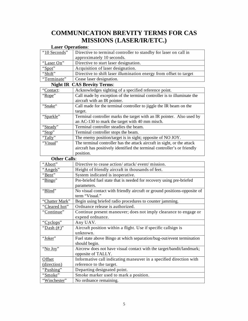
COMMUNICATION BREVITY TERMS FOR CAS MISSIONS (LASER/IR/ETC.)
Laser Operations: “10 Seconds” Directive to terminal controller to standby for laser on call in
approximately 10 seconds. “Laser On” Directive to start laser designation. “Spot” Acquisition of laser designation. “Shift” Directive to shift laser illumination energy from offset to target “Terminate” Cease laser designation.
Night IR CAS Brevity Terms: “Contact: Acknowledges sighting of a specified reference point. “Rope” Call made by exception of the terminal controller is to illuminate the
aircraft with an IR pointer. “Snake“ Call made for the terminal controller to jiggle the IR beam on the
target. “Sparkle” Terminal controller marks the target with an IR pointer. Also used by
an AC-130 to mark the target with 40 mm misch. “Steady” Terminal controller steadies the beam. “Stop” Terminal controller stops the beam. “Tally” The enemy position/target is in sight; opposite of NO JOY. “Visual” The terminal controller has the attack aircraft in sight, or the attack
aircraft has positively identified the terminal controller’s or friendly position.
Other Calls: “Abort” Directive to cease action/attack/event/mission. “Angels” Height of friendly aircraft in thousands of feet. “Bent” System indicated is inoperative. “Bingo” Pre-briefed fuel state that is needed for recovery using pre-briefed
parameters. “Blind” No visual contact with friendly aircraft or ground positions-opposite of
term “Visual.” “Chatter Mark” Begin using briefed radio procedures to counter jamming. “Cleared hot” Ordnance release is authorized. “Continue” Continue present maneuver; does not imply clearance to engage or
expend ordnance. “Cyclops” Any UAV. “Dash (#)” Aircraft position within a flight. Use if specific callsign is
unknown. “Joker” Fuel state above Bingo at which separation/bug-out/event termination
should begin. “No Joy” Aircrew does not have visual contact with the target/bandit/landmark;
opposite of TALLY. Offset (direction)
Informative call indicating maneuver in a specified direction with reference to the target.
“Pushing” Departing designated point. “Smoke” Smoke marker used to mark a position. “Winchester” No ordnance remaining.

6
TARGET WEATHER INFORMATION (TARWI)
GENERAL INFORMATION
The TARWI code is a technique for transmitting detailed information about en route or target area weather observations.
“TARWI example Data given:”
3 6 8 9 X N
The code is read to indicate weather at the target was at 3/8 cloud at 3000 AGL, visibility at least 8 km (5nm), thunderstorms, WX suitable for mission, higher, terrain obscured, thunderstorms en route. # Cloud # Ht (AGL) # Vis (NM) # WX 0 None 0 None 0 0+ 0 Not Obs 1 1/8 1 500 1 1+ 1 None 2 1/4 2 1000 2 2+ 2 Sleet 3 3/8 3 1500 3 3+ 3 Dist/Smoke 4 1/2 4 2000 4 4+ 4 Fog/Haze 5 5/8 5 2500 5 5+ 5 Drizzle 6 3/4 6 3000 6 6+ 6 Rain 7 7/8 7 3500 7 7+ 7 Snow 8 8/8 8 4000 8 8+ 8 Showers 9 Not Obs 9 Not Obs 9 Not Obs 9 T-Storms A WX SIM for Exercise N T-Storms En route B Cloud HT X 10 O Ice/Freezing Rain C No Med Cloud P SFC Wind NEG D Scattered Clouds Q SFC Winds SE E Broken Overcast R SFC Winds SW F Contrails AT FL S SFC Winds NW G Mainly IFR T WX Better North H Mainly VFR U WX Better to East I Gusty SFC Winds V WX Better to South J Fog in Valley W WX Better to West K Hilltops Obscured X WX Suitable L VIS Varies in Showers Y WX Marginal M T-Storms Z WX Unsuitable
7
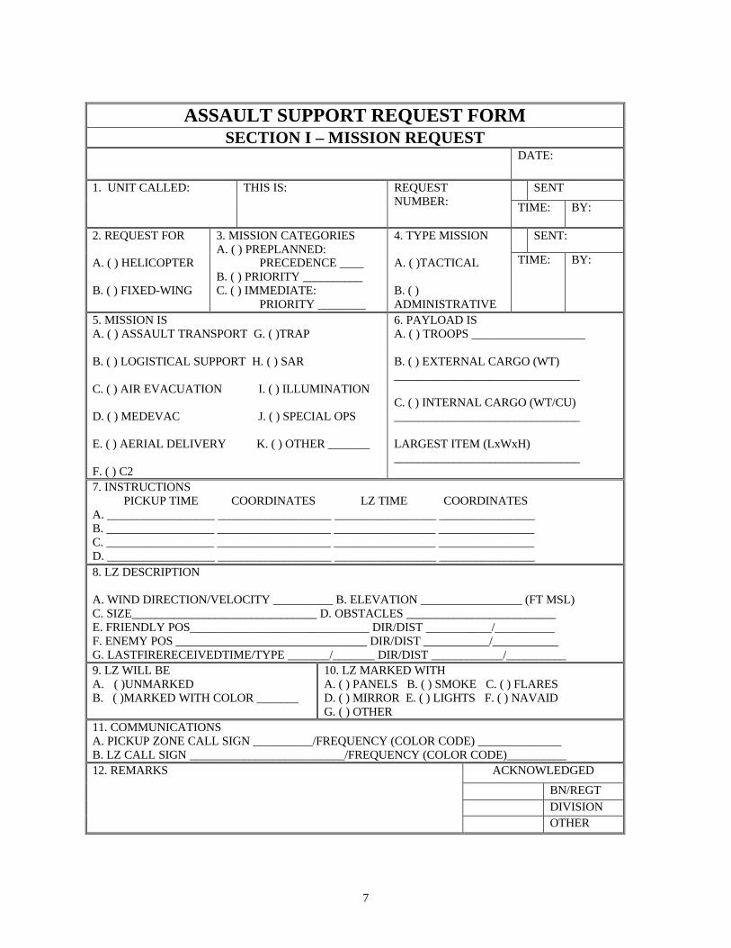
ASSAULT SUPPORT REQUEST FORM SECTION I – MISSION REQUEST
DATE:
SENT 1. UNIT CALLED: THIS IS: REQUEST NUMBER: TIME: BY:
SENT: 2. REQUEST FOR A. ( ) HELICOPTER B. ( ) FIXED-WING
3. MISSION CATEGORIES A. ( ) PREPLANNED:
PRECEDENCE ____ B. ( ) PRIORITY __________ C. ( ) IMMEDIATE:
PRIORITY ________
4. TYPE MISSION A. ( )TACTICAL B. ( ) ADMINISTRATIVE
TIME: BY:
5. MISSION IS A. ( ) ASSAULT TRANSPORT G. ( )TRAP B. ( ) LOGISTICAL SUPPORT H. ( ) SAR C. ( ) AIR EVACUATION I. ( ) ILLUMINATION D. ( ) MEDEVAC J. ( ) SPECIAL OPS E. ( ) AERIAL DELIVERY K. ( ) OTHER _______ F. ( ) C2
6. PAYLOAD IS A. ( ) TROOPS ___________________ B. ( ) EXTERNAL CARGO (WT) _______________________________ C. ( ) INTERNAL CARGO (WT/CU) _______________________________ LARGEST ITEM (LxWxH) _______________________________
7. INSTRUCTIONS PICKUP TIME COORDINATES LZ TIME COORDINATES
A. __________________ ___________________ _________________ ________________ B. __________________ ___________________ _________________ ________________ C. __________________ ___________________ _________________ ________________ D. __________________ ___________________ _________________ ________________ 8. LZ DESCRIPTION A. WIND DIRECTION/VELOCITY __________ B. ELEVATION _________________ (FT MSL) C. SIZE_______________________________ D. OBSTACLES _________________________ E. FRIENDLY POS______________________________ DIR/DIST ___________/__________ F. ENEMY POS ________________________________ DIR/DIST ___________/___________ G. LASTFIRERECEIVEDTIME/TYPE _______/_______ DIR/DIST ____________/__________ 9. LZ WILL BE A. ( )UNMARKED B. ( )MARKED WITH COLOR _______
10. LZ MARKED WITH A. ( ) PANELS B. ( ) SMOKE C. ( ) FLARES D. ( ) MIRROR E. ( ) LIGHTS F. ( ) NAVAID G. ( ) OTHER
11. COMMUNICATIONS A. PICKUP ZONE CALL SIGN __________/FREQUENCY (COLOR CODE) ______________ B. LZ CALL SIGN __________________________/FREQUENCY (COLOR CODE)__________
ACKNOWLEDGED
BN/REGT DIVISION
12. REMARKS
OTHER
8
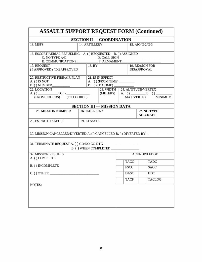
ASSAULT SUPPORT REQUEST FORM (Continued)
SECTION II — COORDINATION 13. MSFS
14. ARTILLERY 15. AIO/G-2/G-3
16. ESCORT/AERIAL REFUELING A. ( ) REQUESTED B. ( ) ASSIGNED C. NO/TYPE A/C __________________ D. CALL SIGN _________________________ E. COMMUNICATIONS_____________ F. ARMAMENT________________________
17. REQUEST ( ) APPROVED ( )DISAPPROVED
18. BY 19. REASON FOR DISAPPROVAL
20. RESTRICTIVE FIRE/AIR PLAN A. ( ) IS NOT B. ( ) NUMBER___________
21. IS IN EFFECT A. ( ) (FROM TIME) _________ B. ( ) (TO TIME) ____________
22. LOCATION A. ( ) ____________ B. ( ) ______________ (FROM COORDS) (TO COORDS)
23. WIDTH (METERS)
24. ALTITUDE/VERTEX A. ( ) _________ B. ( ) __________ MAX/VERTEX MINIMUM
SECTION III — MISSION DATA 25. MISSION NUMBER 26. CALL SIGN 27. NO/TYPE
AIRCRAFT 28. EST/ACT TAKEOFF
29. ETA/ATA
30. MISSION CANCELLED/DIVERTED A. ( ) CANCELLED B. ( ) DIVERTED BY: ____________
31. TERMINATE REQUEST A. ( ) GO/NO GO DTG _____________________
B. ( ) WHEN COMPLETED _________________
ACKNOWLEDGE
TACC TADC
FSCC SACC
DASC HDC
TACP TACLOG
32. MISSION RESULTS A. ( ) COMPLETE B. ( ) INCOMPLETE C. ( ) OTHER ______________________________ NOTES:

9
ASSAULT SUPPORT REQUEST FORM Instructions for Completing
Block Title and Elements Explanation Section I. Mission Request
1. UNIT CALLED Identifies the unit designation/callsign/preassigned number.
THIS IS Identifies the request originator by unit designator/ callsign/preassigned number.
REQUEST NUMBER For preplanned missions, indicates the originator’s request number in series. For immediate missions, this number is assigned by the DASC.
SENT Indicates the time and individual who transmitted the request.
2. REQUEST FOR Indicates whether request is for helicopter or fixed-wing support.
3. MISSION CATEGORIES PREPLANNED:
A. Precedence B. Priority
For preplanned requests, enter precedence (block A) and priority (block B). Precedence is stated numerically in descending order of importance, as determined by the requestor. Priority is expressed as shown below.
IMMEDIATE: C. Priority
For immediate requests, enter priority (block C). A precedence entry is not required for immediate requests because, by definition, all immediate requests are precedence #1.
Use the numerical designation below to determine priority (e.g., define the tactical situation) for preplanned (block B) or immediate (block C).
1. Emergency. Missions which require immediate action and supersede all other categories of mission priority.
2. Priority. Missions which require immediate action and supersede routine missions. For medical evacuation (MEDEVAC), use this category for patients who require specialized treatment not available locally and who are liable to suffer unnecessary pain or disability unless evacuated with the least possible delay.
3. Routine. Missions which do not demand urgency in execution. For MEDEVAC, use this category for patients who can be treated locally, but whose prognosis would benefit by evacuation with the least possible delay.
10
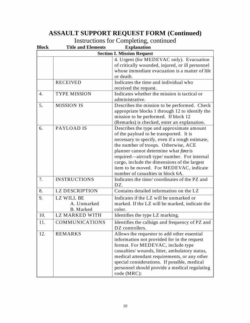
ASSAULT SUPPORT REQUEST FORM (Continued) Instructions for Completing, continued
Block Title and Elements Explanation Section I. Mission Request
4. Urgent (for MEDEVAC only). Evacuation of critically wounded, injured, or ill personnel whose immediate evacuation is a matter of life or death.
RECEIVED Indicates the time and individual who received the request.
4. TYPE MISSION Indicates whether the mission is tactical or administrative.
5. MISSION IS Describes the mission to be performed. Check appropriate blocks 1 through 12 to identify the mission to be performed. If block 12 (Remarks) is checked, enter an explanation.
6. PAYLOAD IS Describes the type and approximate amount of the payload to be transported. It is necessary to specify, even if a rough estimate, the number of troops. Otherwise, ACE planner cannot determine what force is required—aircraft type/number. For internal cargo, include the dimensions of the largest item to be moved. For MEDEVAC, indicate number of casualties in block 6A.
7. INSTRUCTIONS Indicates the time/coordinates of the PZ and DZ.
8. LZ DESCRIPTION Contains detailed information on the LZ
9. LZ WILL BE A. Unmarked B. Marked
Indicates if the LZ will be unmarked or marked. If the LZ will be marked, indicate the color.
10. LZ MARKED WITH Identifies the type LZ marking.
11. COMMUNICATIONS Identifies the callsign and frequency of PZ and DZ controllers.
12. REMARKS
Allows the requestor to add other essential information not provided for in the request format. For MEDEVAC, include type casualties/wounds, litter, ambulatory status, medical attendant requirements, or any other special considerations. If possible, medical personnel should provide a medical regulating code (MRC):
11
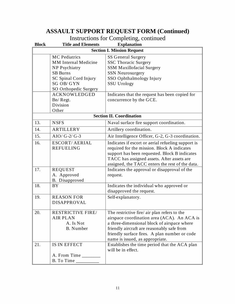
ASSAULT SUPPORT REQUEST FORM (Continued) Instructions for Completing, continued
Block Title and Elements Explanation Section I. Mission Request
MC Pediatrics MM Internal Medicine NP Psychiatry SB Burns SC Spinal Cord Injury SG OB/GYN SO Orthopedic Surgery
SS General Surgery SSC Thoracic Surgery SSM Maxillofacial Surgery SSN Neurosurgery SSO Ophthalmology Injury SSU Urology
ACKNOWLEDGED Bn/Regt. Division Other
Indicates that the request has been copied for concurrence by the GCE.
Section II. Coordination
13. NSFS Naval surface fire support coordination.
14. ARTILLERY Artillery coordination.
15. AIO/G-2/G-3 Air Intelligence Officer, G-2, G-3 coordination.
16. ESCORT/AERIAL REFUELING
Indicates if escort or aerial refueling support is required for the mission. Block A indicates support has been requested. Block B indicates TACC has assigned assets. After assets are assigned, the TACC enters the rest of the data.
17. REQUEST A. Approved B. Disapproved
Indicates the approval or disapproval of the request.
18. BY Indicates the individual who approved or disapproved the request.
19. REASON FOR DISAPPROVAL
Self-explanatory.
20. RESTRICTIVE FIRE/ AIR PLAN
A. Is Not B. Number
The restrictive fire/air plan refers to the airspace coordination area (ACA). An ACA is a three-dimensional block of airspace where friendly aircraft are reasonably safe from friendly surface fires. A plan number or code name is issued, as appropriate.
21. IS IN EFFECT A. From Time ________ B. To Time __________
Establishes the time period that the ACA plan will be in effect.

12
ASSAULT SUPPORT REQUEST FORM (Continued) Instructions for Completing, continued
Block Title and Elements Explanation Section II. Coordination
22. LOCATION A. From Coordinates_____ B. To Coordinates_______
Grid coordinates of the start/end points of the ACA centerline.
23. WIDTH (METERS) Defines the ACA from either side of centerline.
24. ALTITUDE/VERTEX A. Max/Vertex__________ B. Minimum___________
ACA in feet above mean sea level. Use block A for VERTEX only.
Section III. Mission Data
25. MISSION NUMBER Indicates mission number.
26. CALLSIGN Flight callsign of mission aircraft.
27. NO/TYPE AIRCRAFT Self-explanatory.
28. EST/ACT TAKEOFF Estimated or actual time the mission aircraft will take off.
29. ETA/ATA Estimated or actual time of arrival of the mission aircraft in the objective area.
30. MISSION CANCELLED/ DIVERTED
Indicates if mission is cancelled or diverted. By__________ indicates the individual/ agency/ unit who cancelled or diverted the mission.
31. TERMINATE REQUEST
Indicates conditions under which to terminate the request.
32. MISSION RESULTS Self-explanatory, include pilot reports.
MISSION NOTES:
13
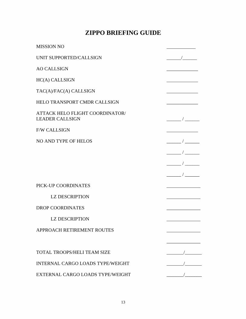
ZIPPO BRIEFING GUIDE MISSION NO ____________ UNIT SUPPORTED/CALLSIGN ______/______ AO CALLSIGN _____________ HC(A) CALLSIGN _____________ TAC(A)/FAC(A) CALLSIGN _____________ HELO TRANSPORT CMDR CALLSIGN _____________ ATTACK HELO FLIGHT COORDINATOR/ LEADER CALLSIGN ______ / ______ F/W CALLSIGN _____________ NO AND TYPE OF HELOS ______ / ______ ______ / ______ ______ / ______ ______ / ______ PICK-UP COORDINATES ______________ LZ DESCRIPTION ______________ DROP COORDINATES ______________ LZ DESCRIPTION ______________ APPROACH RETIREMENT ROUTES ______________ ______________ TOTAL TROOPS/HELI TEAM SIZE _______/_______ INTERNAL CARGO LOADS TYPE/WEIGHT _______/_______ EXTERNAL CARGO LOADS TYPE/WEIGHT _______/_______

14
ZIPPO BRIEFING GUIDE (Continued) ASSAULT FM PRI_______ SEC__________ MISSION COMMON __________________________ ASSAULT UHF PRI_______ SEC__________ GROUND TACTICAL/LZ CONTROL CALLSIGN PRI_______ SEC__________ F/W CONTROL FM/UHF _______/______ WEATHER MINIMUNS/ALTERNATE PLAN _______/______ PICK-UP TIME/LATEST ACCEPTABLE _______/______ L-HOUR/LATEST ACCEPTABLE _______/______ ARTILLERY PREP TIME/END OF MISSION _______/______ F/W FLIGHT/TOS/ORDNANCE _______/______ F/W CAP/TOS/ORDNANCE _______/______ RULES OF ENGAGEMENT/CLEARANCE TO FIRE _______/______ INTELLIGENCE _______/______ REFUEL
MIN BINGO ____#____MINS MISSION UNDERTAKE ____#____MINS LENGTH OF (EST.) ____#____MINS
CASEVAC PRIORITY* ______________
PRECEDENCE** ______________
RESUPPLY
INTERNAL EA SORTIES ___WT#____LIFTS
EXTERNAL ___WT#____LIFTS
15
ZIPPO BRIEFING GUIDE (Continued)
RETURN TO FORCE PROCEDURES PENETRATION CHECKIST MEZ PROCEDURES CORRIDORS ALTITUDES IFF FREQUENCY LAME DUCK PROCEDURES * PRIORITY: Mission priority not used; PRECEDENCE serves the same function. **PRECEDENCE:
a. Urgent - CASEVAC of critically wounded (life or death).
b. Emergency - Safety of U.S. or allied forces or the transport of vital
supplies or equipment.
c. Priority - Tactical transport of personnel or equipment where delay would jeopardize mission. CASEVAC of seriously wounded.
d. Routine - Administrative or tactical transport where time is not a critical
factor.
e. Mandatory - Involves possible loss of life or national prestige.
16
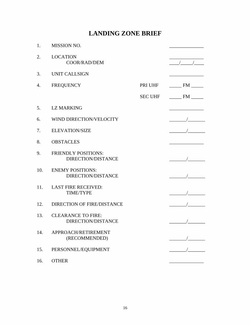
LANDING ZONE BRIEF 1. MISSION NO. ______________ 2. LOCATION ______________
COOR/RAD/DEM ____/_____/____ 3. UNIT CALLSIGN ______________ 4. FREQUENCY PRI UHF _____ FM _____ SEC UHF _____ FM _____ 5. LZ MARKING ______________ 6. WIND DIRECTION/VELOCITY _______/_______ 7. ELEVATION/SIZE _______/_______ 8. OBSTACLES ______________ 9. FRIENDLY POSITIONS: DIRECTION/DISTANCE _______/_______ 10. ENEMY POSITIONS: DIRECTION/DISTANCE _______/_______ 11. LAST FIRE RECEIVED: TIME/TYPE _______/_______ 12. DIRECTION OF FIRE/DISTANCE _______/_______ 13. CLEARANCE TO FIRE: DIRECTION/DISTANCE _______/_______ 14. APPROACH/RETIREMENT (RECOMMENDED) _______/_______ 15. PERSONNEL/EQUIPMENT _______/_______ 16. OTHER ______________
17
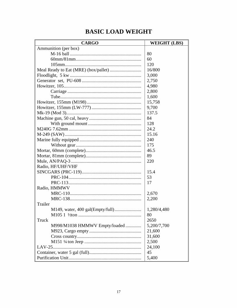
BASIC LOAD WEIGHT
CARGO WEIGHT (LBS) Ammunition (per box) M-16 ball ........................................................... 60mm/81mm...................................................... 105mm............................................................... Meal Ready to Eat (MRE) (box/pallet) .......................... Floodlight, 5 kw ........................................................... Generator set, PU-608 ................................................. Howitzer, 105................................................................ Carriage ............................................................. Tube................................................................... Howitzer, 155mm (M198) ............................................. Howitzer, 155mm (LW-777) ......................................... Mk-19 (Mod 3).............................................................. Machine gun, 50 cal, heavy ........................................... With ground mount ............................................ M240G 7.62mm ............................................................ M-249 (SAW) ............................................................... Marine fully equipped ................................................... Without gear ...................................................... Mortar, 60mm (complete).............................................. Mortar, 81mm (complete).............................................. Mule, AN/PAQ-3 .......................................................... Radio, HF/UHF/VHF SINCGARS (PRC-119)................................................. PRC-104............................................................ PRC-113............................................................ Radio, HMMWV MRC-110........................................................... MRC-138........................................................... Trailer M149, water, 400 gal(Empty/full) ...................... M105 1 ½ ton .................................................... Truck M998/M1038 HMMWV Empty/loaded ............. M923, Cargo empty ........................................... Cross country..................................................... M151 ¼ ton Jeep ............................................... LAV-25......................................................................... Container, water 5 gal (full)........................................... Purification Unit............................................................
80 60 120 16/800 3,000 2,750 4,980 2,800 1,600 15,758 9,700 137.5 84 128 24.2 15.16 240 175 46.5 89 220 15.4 53 17 2,670 2,200 1,280/4,480 80 2650 5,200/7,700 21,600 31,600 2,500 24,100 45 5,400
18
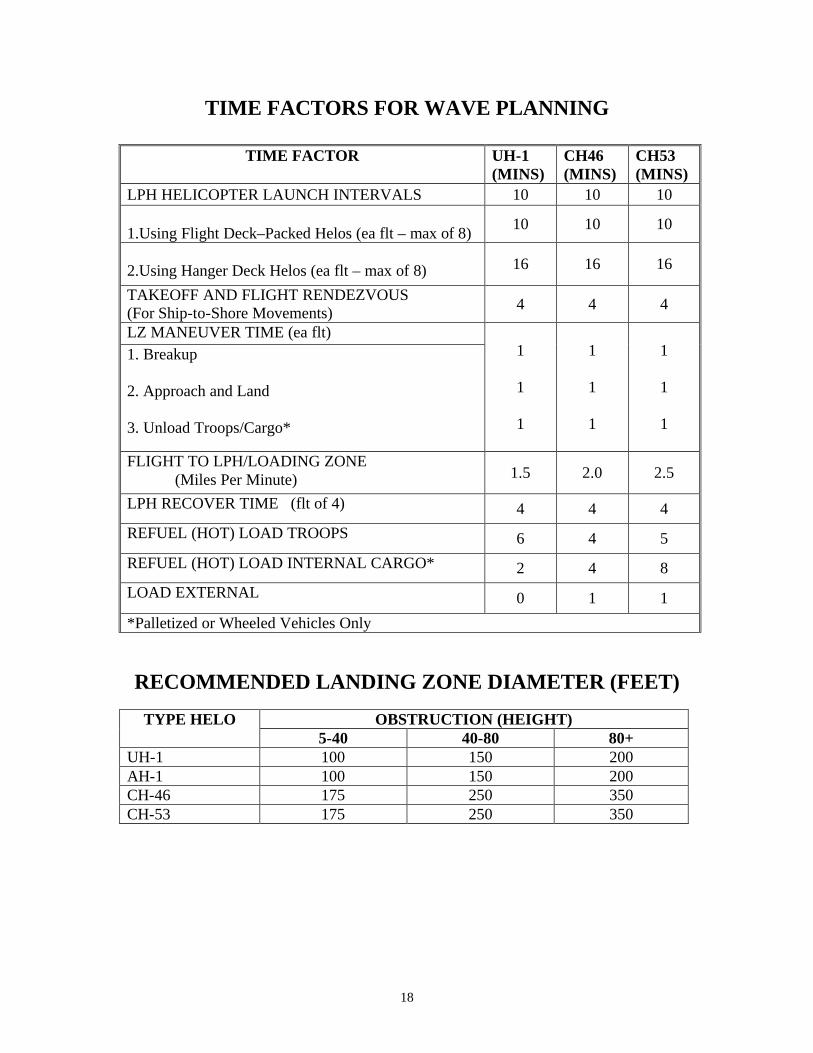
TIME FACTORS FOR WAVE PLANNING
TIME FACTOR UH-1 (MINS)
CH46 (MINS)
CH53 (MINS)
LPH HELICOPTER LAUNCH INTERVALS 10 10 10 1.Using Flight Deck–Packed Helos (ea flt – max of 8)
10 10 10
2.Using Hanger Deck Helos (ea flt – max of 8) 16 16 16
TAKEOFF AND FLIGHT RENDEZVOUS (For Ship-to-Shore Movements)
4 4 4
LZ MANEUVER TIME (ea flt) 1. Breakup 2. Approach and Land 3. Unload Troops/Cargo*
1
1
1
1
1
1
1
1
1
FLIGHT TO LPH/LOADING ZONE (Miles Per Minute) 1.5 2.0 2.5
LPH RECOVER TIME (flt of 4) 4 4 4
REFUEL (HOT) LOAD TROOPS 6 4 5
REFUEL (HOT) LOAD INTERNAL CARGO* 2 4 8
LOAD EXTERNAL 0 1 1
*Palletized or Wheeled Vehicles Only
RECOMMENDED LANDING ZONE DIAMETER (FEET)
OBSTRUCTION (HEIGHT) TYPE HELO 5-40 40-80 80+
UH-1 100 150 200 AH-1 100 150 200 CH-46 175 250 350 CH-53 175 250 350
19
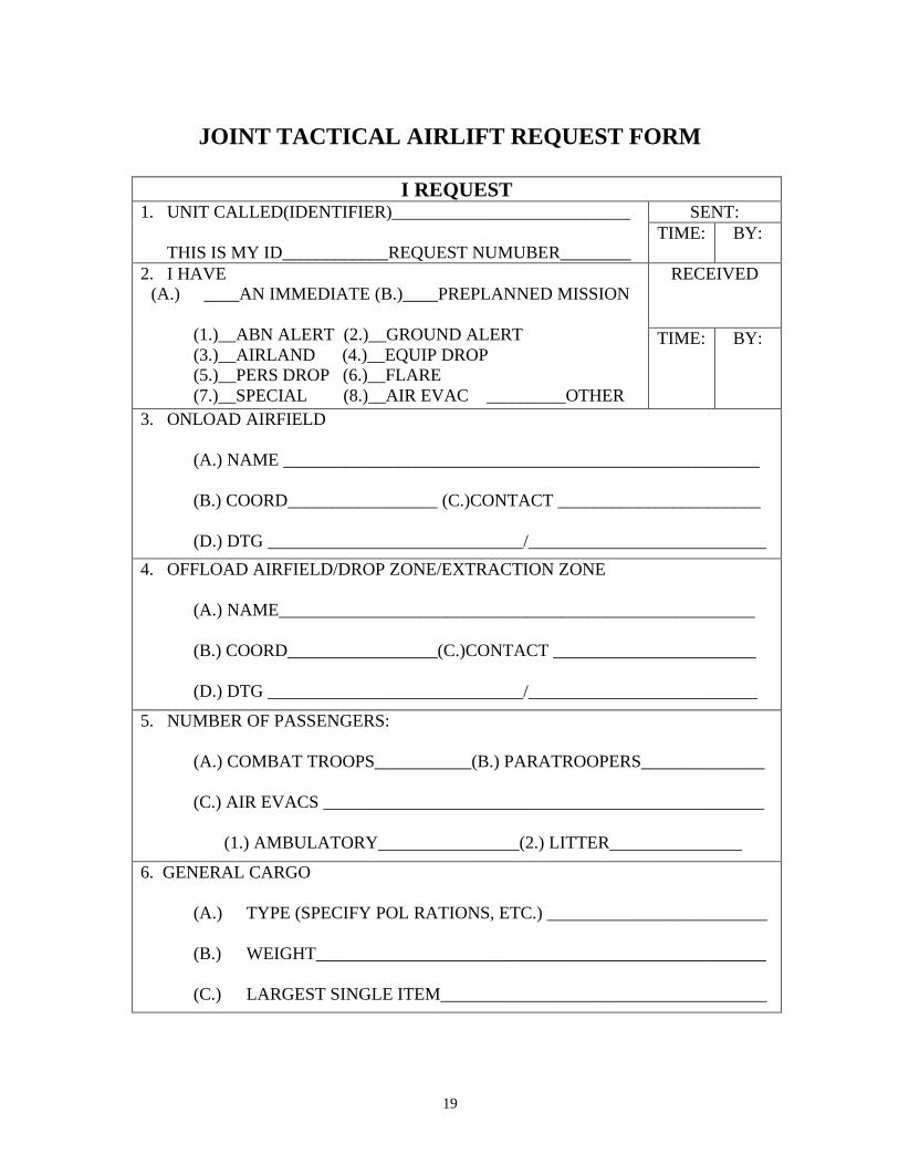
JOINT TACTICAL AIRLIFT REQUEST FORM
I REQUEST SENT: 1. UNIT CALLED(IDENTIFIER)___________________________
THIS IS MY ID____________REQUEST NUMUBER________
TIME: BY:
RECEIVED 2. I HAVE (A.) ____AN IMMEDIATE (B.)____PREPLANNED MISSION
(1.)__ABN ALERT (2.)__GROUND ALERT (3.)__AIRLAND (4.)__EQUIP DROP (5.)__PERS DROP (6.)__FLARE (7.)__SPECIAL (8.)__AIR EVAC _________OTHER
TIME: BY:
3. ONLOAD AIRFIELD (A.) NAME ______________________________________________________ (B.) COORD_________________ (C.)CONTACT _______________________
(D.) DTG _____________________________/___________________________
4. OFFLOAD AIRFIELD/DROP ZONE/EXTRACTION ZONE (A.) NAME______________________________________________________ (B.) COORD_________________(C.)CONTACT _______________________ (D.) DTG _____________________________/__________________________
5. NUMBER OF PASSENGERS: (A.) COMBAT TROOPS___________(B.) PARATROOPERS______________ (C.) AIR EVACS __________________________________________________
(1.) AMBULATORY________________(2.) LITTER_______________
6. GENERAL CARGO (A.) TYPE (SPECIFY POL RATIONS, ETC.) _________________________ (B.) WEIGHT___________________________________________________ (C.) LARGEST SINGLE ITEM_____________________________________
20
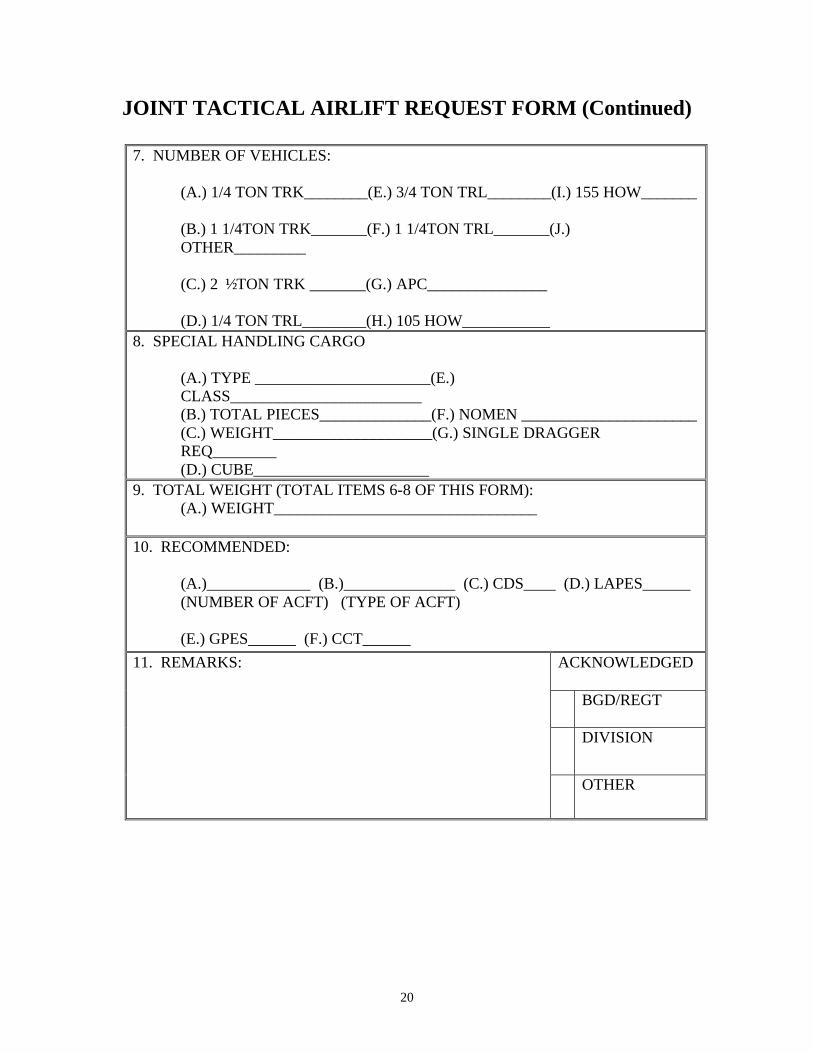
JOINT TACTICAL AIRLIFT REQUEST FORM (Continued)
7. NUMBER OF VEHICLES:
(A.) 1/4 TON TRK________(E.) 3/4 TON TRL________(I.) 155 HOW_______ (B.) 1 1/4TON TRK_______(F.) 1 1/4TON TRL_______(J.) OTHER_________ (C.) 2 ½ TON TRK _______(G.) APC_______________ (D.) 1/4 TON TRL________(H.) 105 HOW___________
8. SPECIAL HANDLING CARGO (A.) TYPE ______________________(E.) CLASS________________________ (B.) TOTAL PIECES______________(F.) NOMEN ______________________ (C.) WEIGHT____________________(G.) SINGLE DRAGGER REQ________ (D.) CUBE______________________
9. TOTAL WEIGHT (TOTAL ITEMS 6-8 OF THIS FORM): (A.) WEIGHT_________________________________
10. RECOMMENDED: (A.)_____________ (B.)______________ (C.) CDS____ (D.) LAPES______ (NUMBER OF ACFT) (TYPE OF ACFT) (E.) GPES______ (F.) CCT______
ACKNOWLEDGED BGD/REGT
DIVISION
11. REMARKS:
OTHER
21
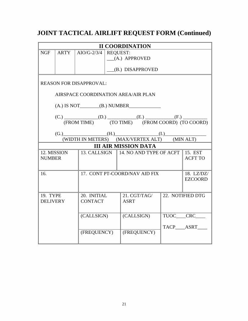
JOINT TACTICAL AIRLIFT REQUEST FORM (Continued)
II COORDINATION NGF ARTY AIO/G-2/3/4 REQUEST:
___(A.) APPROVED ___(B.) DISAPPROVED
REASON FOR DISAPPROVAL:
AIRSPACE COORDINATION AREA/AIR PLAN (A.) IS NOT________(B.) NUMBER_____________ (C.) ______________(D.) ____________(E.) ____________(F.) __________ (FROM TIME) (TO TIME) (FROM COORD) (TO COORD) (G.)__________________(H.)__________________(I.)_________________ (WIDTH IN METERS) (MAX/VERTEX ALT) (MIN ALT)
III AIR MISSION DATA 12. MISSION NUMBER
13. CALLSIGN 14. NO AND TYPE OF ACFT 15. EST ACFT TO
16. 17. CONT PT-COORD/NAV AID FIX 18. LZ/DZ/ EZCOORD
20. INITIAL CONTACT
21. CGT/TAG/ ASRT
22. NOTIFIED DTG
(CALLSIGN) (CALLSIGN)
19. TYPE DELIVERY
(FREQUENCY) (FREQUENCY)
TUOC____CRC____ TACP____ASRT____

22
(This page intentionally left blank.)
23
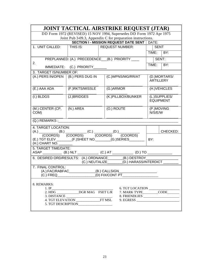
JOINT TACTICAL AIRSTRIKE REQUEST (JTAR) DD Form 1972 (REVISED) 15 NOV 1994, Supersedes DD Form 1972 Apr 1975
Joint Pub 3-09.3, Appendix C for preparation instructions. SECTION I - MISSION REQUEST DATE SENT DATE:
SENT 1. UNIT CALLED: THIS IS: REQUEST NUMBER:
TIME: BY:
SENT: PREPLANNED: (A.) PRECEDENCE___(B.) PRIORITY ____ 2.
IMMEDIATE: (C.) PRIORITY_______ TIME: BY:
3. TARGET IS/NUMBER OF: (A.) PERS IN/OPEN ________________
(B.) PERS DUG IN ________________
(C.)WPNS/MG/RR/AT ___________________
(D.)MORTARS/ ARTILLERY _______________
(E.) AAA ADA ________________
(F.)RKTS/MISSLE _______________
(G.)ARMOR ___________
(H.)VEHICLES _______________
(I.) BLDGS ________________
(J.)BRIDGES __________________
(K.)PILLBOX/BUNKER ___________________
(L.)SUPPLIES/ EQUIPMENT _______________
(M.) CENTER (CP, COM) ________________
(N.) AREA __________________
(O.) ROUTE ___________________
(P.)MOVING N/S/E/W _______________
(Q.) REMARKS ;_______________________________________________________________
CHECKED:
4. TARGET LOCATION: (A.) __________ (B.) ___________ (C.) __________(D.)___________ (COORDS) (COORDS) (COORDS) (COORDS) (E.) TGT ELEV ________(F.)SHEET NO.________(G.)SERIES________ (H.) CHART NO. _______
BY:
5. TARGET TIME/DATE: ASAP __________ (B.) NLT ___________ (C.) AT ___________ (D.) TO _____________
6. DESIRED ORD/RESULTS: (A.) ORDNANCE________(B.) DESTROY_________________ (C.) NEUTALIZE________(D.) HARASS/INTERDICT ________
7. FINAL CONTROL: (A.) FAC/RABFAC______________(B.) CALLSIGN____________________ (C.) FREQ____________________(D) FIX/CONT PT___________________
8. REMARKS:
1. IP____________________________________ 2. HDG _____________DGR MAG FSET L/R 3. DISTANCE ___________________________ 4. TGT ELEVATION ______________FT MSL 5. TGT DESCRIPTION____________________
6. TGT LOCATION __________________ 7. MARK TYPE_________CODE_______ 8. FRIENDLIES _____________________ 9. EGRESS _________________________

24
JOINT TACTICAL AIRSTRIKE REQUEST (JTAR) (Continued)
SECTION II –COORDINATION 9. NGF 10. ARTY 11. AIO/G-2/G-3
12. REQUEST: (A.) ______APPROVE (B.) ______DISAPPROVE
13. BY: 14. REASON FOR DISAPPROVAL:
15. AIRSPACE COURDINATION AREA (ACA):
(A.) IS NOT IN EFFECT______ (B.) NUMBER ______________
16. IS IN EFFECT (A.) FROM TIME __________________ (B.) TO TIME _____________________
17. LOCATION: (A.) __________ (B.) ______________ (FROM COORDS) (TO COORDS)
18. WIDTH (IN METERS):
19. ALTITUDE/VERTEX: (A.)___________ (B.) _________________ (MAX/VERTEX) (MINIMUMVERTEX)
SECTION III – MISSION DATA 20. MISSION NO: 21. CALLSIGN: 22. NO. AND TYPE AIRCRAFT: 23. ORDNANCE:
24. EST/ACT TAKEOFF:
25. EST TOT: 26. CONT PT/RDNVS (COORDS/NAVAID FIX)
27. INTIAL CONTACT:
28. FAC/ASRT/TAC(A) CALLSIGN FREQ:
29. RESTRICTIVE FIRE/AIR PLAN (SEE 15-19):
30. TGT DESCRIPTION: 31.TGT COORD/ ELEV:
32. BATTLE DAMAGE ASSESSMENT (BDA) REPORT (USMTF INFLTREP): LINE 1/ CALL SIGN __________________ LINE 4/LOCATION __________________ LINE 2/ MISSION NUMBER ___________ LINE 5/TOT_________________________ LINE 3/ REQUEST NUMBER___________ LINE 6/RESULTS ____________________
TUOC
CRC
TACP
MISSION REMARKS/INFORMATION:
ASRT

25
JOINT TACTICAL AIRSTRIKE REQUEST (JTAR) INSTRUCTIONS
SECTION I - MISSION REQUEST Line Title and Elements Explanation 1. Unit Called Identifies the unit designation/call-
sign/pre-assigned number. This is Identifies the request originator by unit designation/callsign/pre- assigned number.
Request Number For preplanned missions, indicates
the originator’s request number in series. For immediate missions, this number is assigned by the ASOC/DASC.
Sent Indicates the time and the individual
who transmitted the request. 2. (Mission categories)
Preplanned: A. Precedence For preplanned requests, enter
precedence(block A). B. Priority or priority (block B). Precedence is
stated numerically in descending order of importance, as determined by the requester. Priority is expressed as shown below.
Immediate: C. Priority For immediate requests, enter priority
(block). A precedence entry is not required for immediate requests because, by definition, all immediate requests have a precedence of 1.
Use the numerical designation below to determine priority (e.g., define the tactical situation) for preplanned (block B) or immediate (block C): 1. Emergency: Targets that require
immediate action and supersede all other categories of mission priority.
26
JOINT TACTICAL AIRSTRIKE REQUEST (JTAR) INSTRUCTIONS (Continued)
SECTION I - MISSION REQUEST Line Title and Elements Explanation
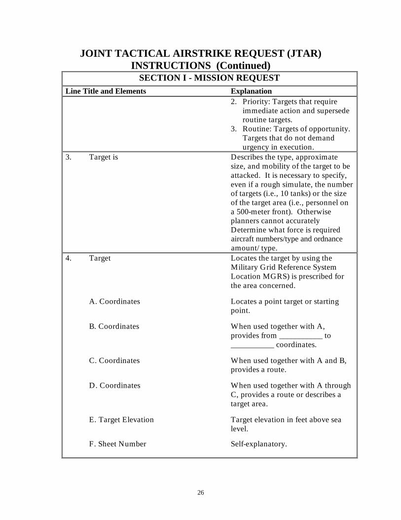
2. Priority: Targets that require immediate action and supersede routine targets.
3. Routine: Targets of opportunity. Targets that do not demand urgency in execution.
3. Target is Describes the type, approximate size, and mobility of the target to be attacked. It is necessary to specify, even if a rough simulate, the number of targets (i.e., 10 tanks) or the size of the target area (i.e., personnel on a 500-meter front). Otherwise planners cannot accurately Determine what force is required aircraft numbers/type and ordnance amount/type.
4. Target Locates the target by using the Military Grid Reference System Location MGRS) is prescribed for the area concerned.
A. Coordinates Locates a point target or starting point.
B. Coordinates When used together with A, provides from ___________ to ___________ coordinates.
C. Coordinates When used together with A and B, provides a route.
D. Coordinates When used together with A through C, provides a route or describes a target area.
E. Target Elevation Target elevation in feet above sea level.
F. Sheet Number Self-explanatory.
27
JOINT TACTICAL AIRSTRIKE REQUEST (JTAR) INSTRUCTIONS (Continued) SECTION I - MISSION REQUEST
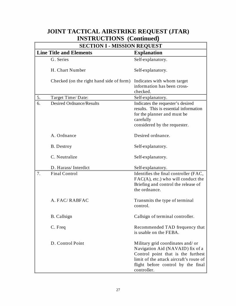
Line Title and Elements Explanation G. Series Self-explanatory. H. Chart Number Self-explanatory. Checked (on the right hand side of form) Indicates with whom target
information has been cross-checked.
5. Target Time/Date: Self-explanatory. 6. Desired Ordnance/Results Indicates the requester’s desired
results. This is essential information for the planner and must be carefully considered by the requester.
A. Ordnance Desired ordnance. B. Destroy Self-explanatory. C. Neutralize Self-explanatory. D. Harass/Interdict Self-explanatory.
7. Final Control Identifies the final controller (FAC, FAC(A), etc.) who will conduct the Briefing and control the release of the ordnance.
A. FAC/RABFAC Transmits the type of terminal
control. B. Callsign Callsign of terminal controller. C. Freq Recommended TAD frequency that
is usable on the FEBA. D. Control Point Military grid coordinates and/or
Navigation Aid (NAVAID) fix of a Control point that is the furthest limit of the attack aircraft’s route of flight before control by the final controller.
28
JOINT TACTICAL AIRSTRIKE REQUEST (JTAR) INSTRUCTIONS (Continued)
SECTION I - MISSION REQUEST
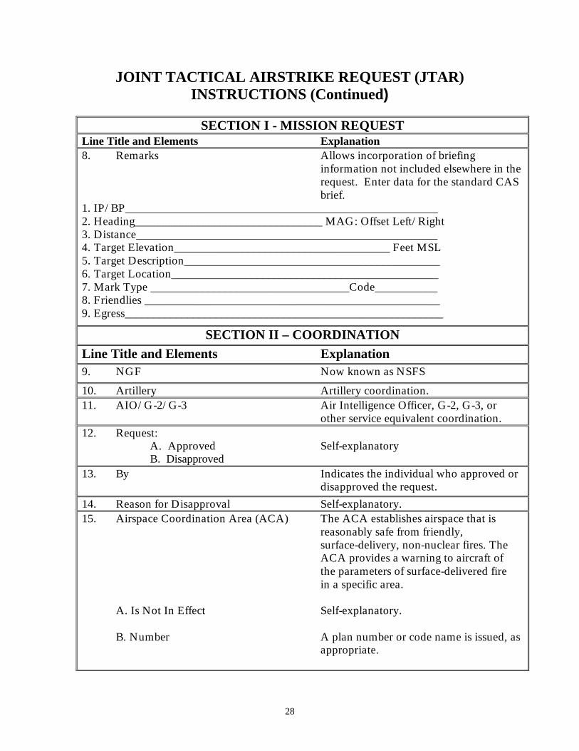
Line Title and Elements Explanation 8. Remarks Allows incorporation of briefing
information not included elsewhere in the request. Enter data for the standard CAS brief.
1. IP/BP_______________________________________________________ 2. Heading_________________________________ MAG: Offset Left/Right 3. Distance_____________________________________________________ 4. Target Elevation______________________________________ Feet MSL 5. Target Description_____________________________________________ 6. Target Location_______________________________________________ 7. Mark Type ___________________________________Code___________ 8. Friendlies ____________________________________________________ 9. Egress________________________________________________________
SECTION II – COORDINATION
Line Title and Elements Explanation 9. NGF Now known as NSFS
10. Artillery Artillery coordination. 11. AIO/G-2/G-3 Air Intelligence Officer, G-2, G-3, or
other service equivalent coordination. 12. Request:
A. Approved Self-explanatory B. Disapproved
13. By Indicates the individual who approved or disapproved the request.
14. Reason for Disapproval Self-explanatory. 15. Airspace Coordination Area (ACA) The ACA establishes airspace that is
reasonably safe from friendly, surface-delivery, non-nuclear fires. The ACA provides a warning to aircraft of the parameters of surface-delivered fire in a specific area.
A. Is Not In Effect Self-explanatory. B. Number A plan number or code name is issued, as
appropriate.
29
JOINT TACTICAL AIRSTRIKE REQUEST INSTRUCTIONS (Continued)
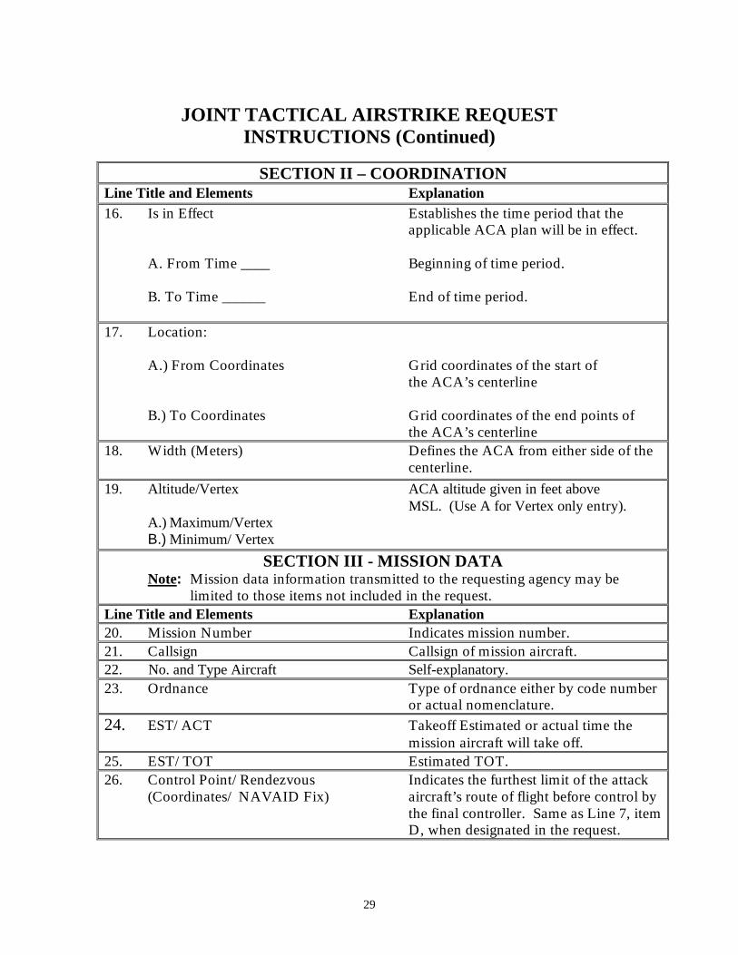
SECTION II – COORDINATION Line Title and Elements Explanation 16. Is in Effect Establishes the time period that the
applicable ACA plan will be in effect. A. From Time ____ Beginning of time period. B. To Time ______ End of time period.
17. Location: A.) From Coordinates Grid coordinates of the start of
the ACA’s centerline B.) To Coordinates Grid coordinates of the end points of
the ACA’s centerline 18. Width (Meters) Defines the ACA from either side of the
centerline.
19. Altitude/Vertex ACA altitude given in feet above MSL. (Use A for Vertex only entry).
A.) Maximum/Vertex B.) Minimum/ Vertex
SECTION III - MISSION DATA Note: Mission data information transmitted to the requesting agency may be
limited to those items not included in the request. Line Title and Elements Explanation 20. Mission Number Indicates mission number. 21. Callsign Callsign of mission aircraft. 22. No. and Type Aircraft Self-explanatory. 23. Ordnance Type of ordnance either by code number
or actual nomenclature. 24. EST/ACT Takeoff Estimated or actual time the
mission aircraft will take off. 25. EST/TOT Estimated TOT. 26. Control Point/Rendezvous Indicates the furthest limit of the attack
(Coordinates/ NAVAID Fix) aircraft’s route of flight before control by the final controller. Same as Line 7, item D, when designated in the request.
30
JOINT TACTICAL AIRSTRIKE REQUEST INSTRUCTIONS (Continued)
SECTION III - MISSION DATA
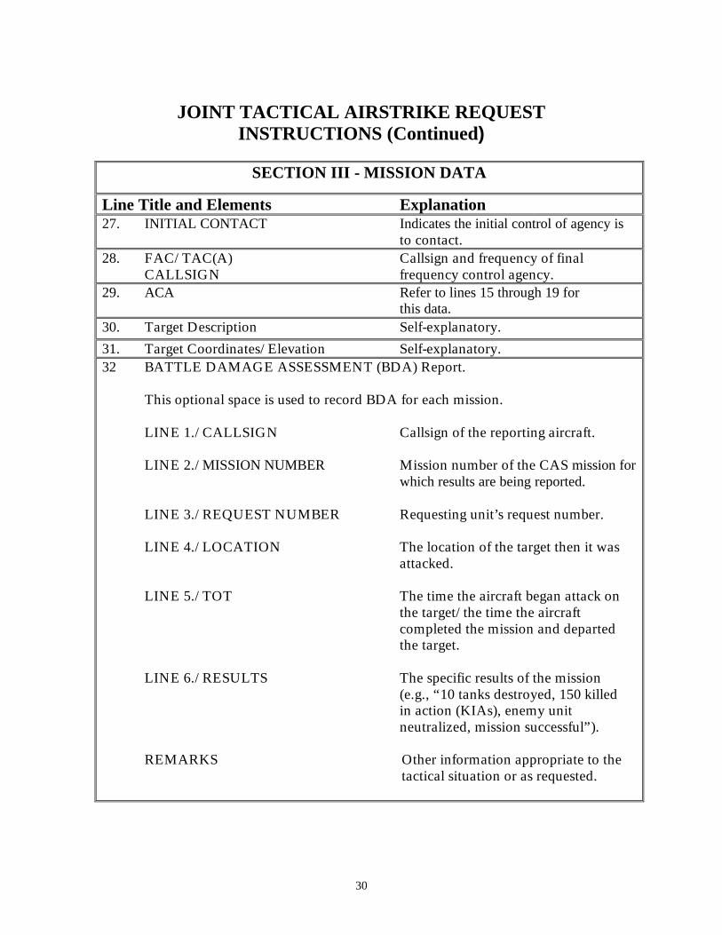
Line Title and Elements Explanation 27. INITIAL CONTACT Indicates the initial control of agency is
to contact. 28. FAC/TAC(A) Callsign and frequency of final
CALLSIGN frequency control agency. 29. ACA Refer to lines 15 through 19 for
this data. 30. Target Description Self-explanatory.
31. Target Coordinates/Elevation Self-explanatory. 32 BATTLE DAMAGE ASSESSMENT (BDA) Report.
This optional space is used to record BDA for each mission.
LINE 1./CALLSIGN Callsign of the reporting aircraft. LINE 2./MISSION NUMBER Mission number of the CAS mission for
which results are being reported. LINE 3./REQUEST NUMBER Requesting unit’s request number. LINE 4./LOCATION The location of the target then it was
attacked. LINE 5./TOT The time the aircraft began attack on
the target/the time the aircraft completed the mission and departed the target.
LINE 6./RESULTS The specific results of the mission
(e.g., “10 tanks destroyed, 150 killed in action (KIAs), enemy unit
neutralized, mission successful”).
REMARKS Other information appropriate to the tactical situation or as requested.

31
CAS CHECK-IN BRIEF FORM (Aircraft Transmits to Controller)
Aircraft: “____________________________ this is __________________________” (Controller Callsign) (Aircraft Callsign) 1. Identification/ Mission Number: “_______________________________________” Note: Authentication and appropriate response suggested here. The brief may be
abbreviated for brevity or security (“as fragged” or “by exception”). 2. Number and Type of Aircraft: “_________________________________________” 3. Position and Altitude: “________________________________________________” 4. Ordnance: “_________________________________________________________” 5. Time on station (TOS): “_______________________________________________” 6. Abort Code: “_______________________________________________________” (If applicable) Remarks: “__________________________________(NVG, LST, special mission info)
CAS MULTI-MISSION “9 LINE” FORM
ACFT ON STATION FOR CONTROL
“STBY FOR A NINE LINE…”
A/C CS ________ MSN#_________ #/TYPE________ POS___________ ALT___________ ORD __________ TOS___________ ABT CODE_____ RMKS_________
A/C CS ________ MSN#_________ #/TYPE________ POS___________ ALT___________ ORD __________ TOS___________ ABT CODE_____ RMKS_________
A/C CS ________ MSN#_________ #/TYPE________ POS___________ ALT___________ ORD __________ TOS___________ ABT CODE_____ RMKS_________
1. IP/ BP 2. HDG (DEG MAG) L / R L / R L / R 3. DISTANCE (NM / MTRS)
4. TGT ELEV ( FT MSL) 5. TGT DESC (GENERAL)
6. TGT LOCATE(GRID) 7. MARK (CODE/ LTL) 8. FRIENDLIES (DIR/ DIST)
9. “EGRESS…” (DIR&DEST)
REMARKS: RESTRICTION (FAH OR ALT) THREATS, ACA (SEAD GTL)…
TOT / TTT AMPLIFYING INFORMATION (AS REQD)
32
CLOSE AIR SUPPORT (CAS) THE “9 LINE” BRIEF INSTRUCTIONS
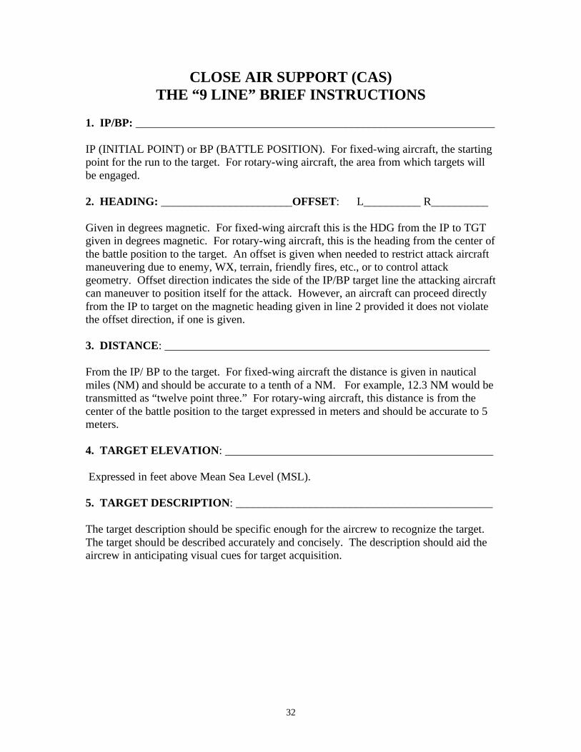
1. IP/BP: _______________________________________________________________ IP (INITIAL POINT) or BP (BATTLE POSITION). For fixed-wing aircraft, the starting point for the run to the target. For rotary-wing aircraft, the area from which targets will be engaged. 2. HEADING: _______________________OFFSET: L__________ R__________ Given in degrees magnetic. For fixed-wing aircraft this is the HDG from the IP to TGT given in degrees magnetic. For rotary-wing aircraft, this is the heading from the center of the battle position to the target. An offset is given when needed to restrict attack aircraft maneuvering due to enemy, WX, terrain, friendly fires, etc., or to control attack geometry. Offset direction indicates the side of the IP/BP target line the attacking aircraft can maneuver to position itself for the attack. However, an aircraft can proceed directly from the IP to target on the magnetic heading given in line 2 provided it does not violate the offset direction, if one is given. 3. DISTANCE: _________________________________________________________ From the IP/ BP to the target. For fixed-wing aircraft the distance is given in nautical miles (NM) and should be accurate to a tenth of a NM. For example, 12.3 NM would be transmitted as “twelve point three.” For rotary-wing aircraft, this distance is from the center of the battle position to the target expressed in meters and should be accurate to 5 meters. 4. TARGET ELEVATION: _______________________________________________ Expressed in feet above Mean Sea Level (MSL). 5. TARGET DESCRIPTION: _____________________________________________ The target description should be specific enough for the aircrew to recognize the target. The target should be described accurately and concisely. The description should aid the aircrew in anticipating visual cues for target acquisition.

33
CLOSE AIR SUPPORT (CAS) BRIEF THE “9 LINE” BRIEF (Continued)
6. TARGET LOCATION: ________________________________________________ The location of the target can be given in several ways; 6-digit UTM grid coordinates, latitude and longitude, navigation aid fix, or visual description from a conspicuous reference point are all acceptable. Because multiple grid coordinate system datum is in use, the specific datum being referenced should be specified in the JTAR and, if required, clarified by the brief. Terminal controllers should include the 100,000 meter grid identification. For area targets, use the center of the area or the location of the greatest concentration of enemy. For linear targets, use the ends of the target array. 7. MARK TYPE: __________________ CODE: _______________ LTL: _________ Type of mark to be employed--white phosphorous, illumination, IR pointer, laser, etc. If a laser designator is being employed, the four-digit laser code and the laser-to-target line are stated. 8. FRIENDLIES: _______________________________________________________ The location of friendly forces nearest the target is given. This position is referenced from the target—from the target to the position—and is expressed in a cardinal or semi-cardinal direction and a distance in meters. If the friendly position is marked, identify the type of mark. 9. EGRESS: ____________________________________________________________ The cardinal or semi-cardinal direction to be used when departing the target and control points to use when exiting the terminal control arena. Unlike all other lines of the brief, the word “egress” is transmitted before giving egress instructions. REMARKS: ____________________________________________________________ The following information may be included if applicable:
• Troops in contact or danger close • Airspace coordination: final attack heading (FAH) or altitude restrictions • Threat • SEAD support in effect • Active gun target lines • Ordnance requested • Hazards • Weather

34
CLOSE AIR SUPPORT (CAS) BRIEF THE “9 LINE” BRIEF (Continued)
TOT/TTT: ______________________________________________________________
OR TTT: ______________________________________________________________ The terminal controller will assign a TOT (time-on-target) or TTT (time-to-target).
• TOT. (GPS Default Method) Time-on-target is the specific time aircraft delivered ordnance will hit the target. The timing is based on a synchronized clock, GPS is the standard, that is used by all supporting arms agencies.
• TTT. Time–to-target uses a countdown timer rather than a universal clock.
The terminal controller states the number of minutes and seconds to elapse from the time the countdown is started to the time aircraft delivered ordnance hits the target; the countdown is started with the word “HACK.” For example, if the terminal controller were to say “six plus zero zero (6+00)…HACK,” ordnance should impact the target six minutes after the “HACK” was transmitted. Any other supporting arms/ ground elements involved in the mission must coordinate their timing from this countdown and “HACK.”
CAS MISSION NOTES:

35
CAS CHECK-OUT BRIEF (BDA REPORT)
Aircraft: “____________________________ this is __________________________” (Controller Callsign) (Aircraft Callsign) Note: Authentication and appropriate response suggested here. The brief may be abbreviated for brevity or security (“as fragged” or “by exception”). LINE 1.) CALLSIGN: “________________________________________________” LINE 2.) MISSION NUMBER: “________________________________________” LINE 3.) REQUEST NUMBER/JTAR: “__________________________________” LINE 4.) LOCATION: “_______________________________________________” LINE 5.) TIME ON TARGET: “_________________________________________” LINE 6.) RESULTS: “ _________________________________________________” REMARKS: “________________________________________________________”
(Target area weather, significant sightings, EEIs…)
36
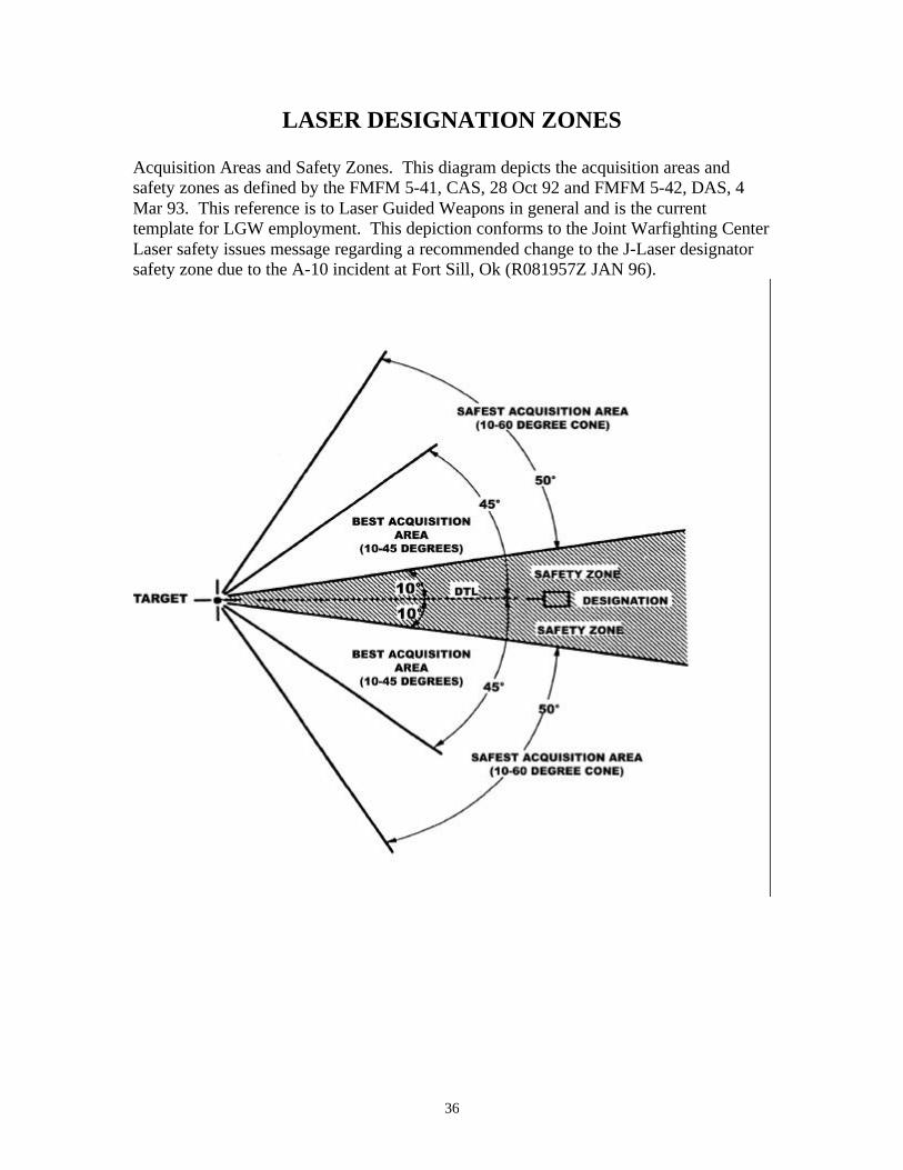
LASER DESIGNATION ZONES
Acquisition Areas and Safety Zones. This diagram depicts the acquisition areas and safety zones as defined by the FMFM 5-41, CAS, 28 Oct 92 and FMFM 5-42, DAS, 4 Mar 93. This reference is to Laser Guided Weapons in general and is the current template for LGW employment. This depiction conforms to the Joint Warfighting Center Laser safety issues message regarding a recommended change to the J-Laser designator safety zone due to the A-10 incident at Fort Sill, Ok (R081957Z JAN 96).
37
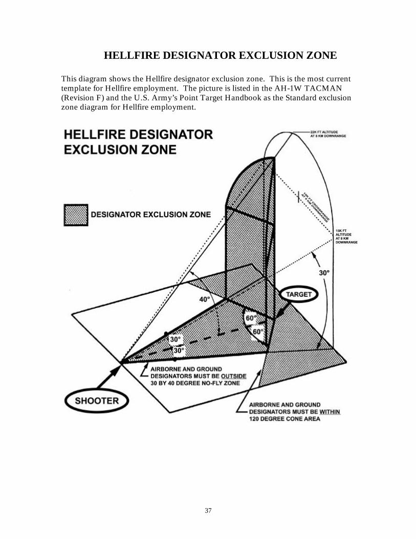
HELLFIRE DESIGNATOR EXCLUSION ZONE
This diagram shows the Hellfire designator exclusion zone. This is the most current template for Hellfire employment. The picture is listed in the AH-1W TACMAN (Revision F) and the U.S. Army’s Point Target Handbook as the Standard exclusion zone diagram for Hellfire employment.

38
HELLFIRE MISSILE SURFACE DANGER ZONES (W/LASER)
This figure depicts the Surface Danger Zone (SDZ) for a Hellfire launch in which the missile was receiving laser energy prior to launch, regardless of the mode selected. Because of the large surface danger zone and the limited range of the designators, it may be necessary to place designator operators within the surface danger zone.
39
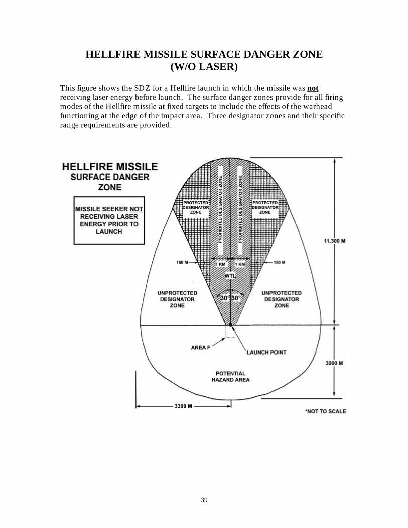
HELLFIRE MISSILE SURFACE DANGER ZONE (W/O LASER)
This figure shows the SDZ for a Hellfire launch in which the missile was not receiving laser energy before launch. The surface danger zones provide for all firing modes of the Hellfire missile at fixed targets to include the effects of the warhead functioning at the edge of the impact area. Three designator zones and their specific range requirements are provided.

40
(This page intentionally left blank.)
41
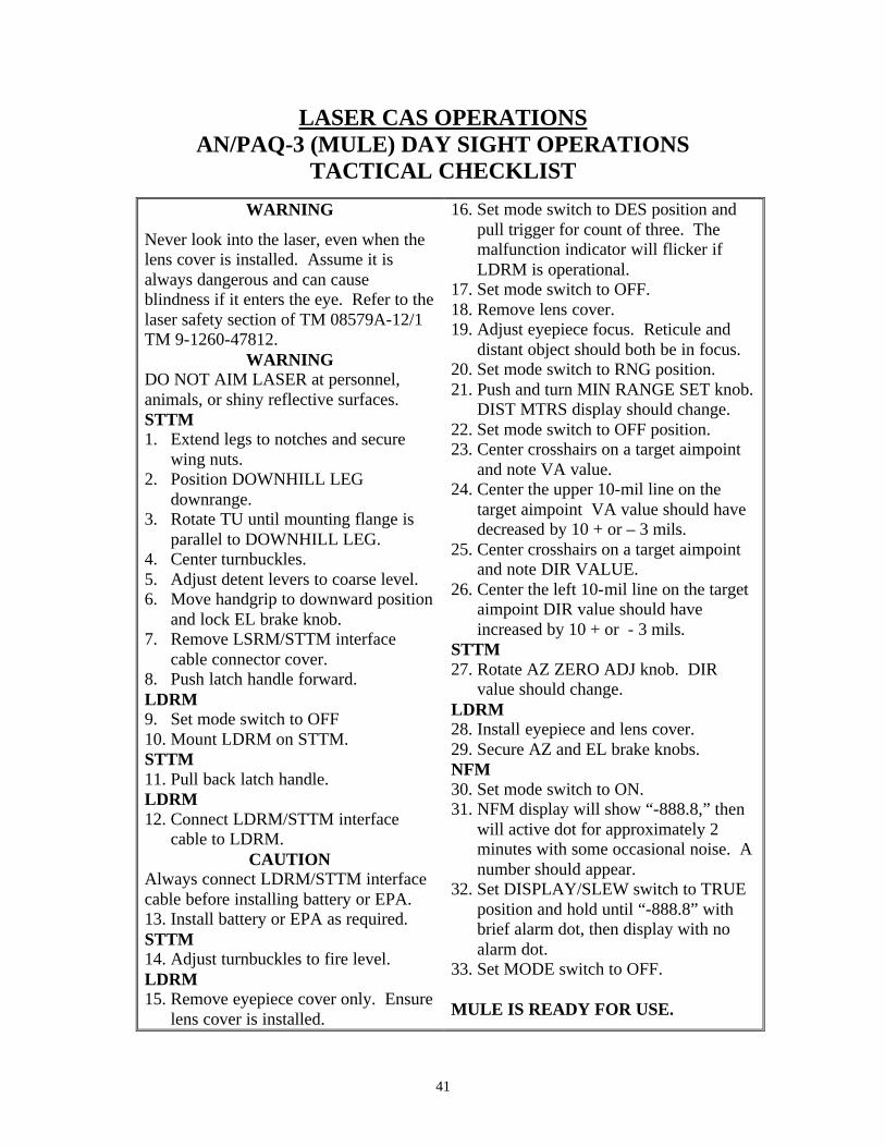
LASER CAS OPERATIONS AN/PAQ-3 (MULE) DAY SIGHT OPERATIONS
TACTICAL CHECKLIST
WARNING
Never look into the laser, even when the lens cover is installed. Assume it is always dangerous and can cause blindness if it enters the eye. Refer to the laser safety section of TM 08579A-12/1 TM 9-1260-47812.
WARNING DO NOT AIM LASER at personnel, animals, or shiny reflective surfaces. STTM 1. Extend legs to notches and secure
wing nuts. 2. Position DOWNHILL LEG
downrange. 3. Rotate TU until mounting flange is
parallel to DOWNHILL LEG. 4. Center turnbuckles. 5. Adjust detent levers to coarse level. 6. Move handgrip to downward position
and lock EL brake knob. 7. Remove LSRM/STTM interface
cable connector cover. 8. Push latch handle forward. LDRM 9. Set mode switch to OFF 10. Mount LDRM on STTM. STTM 11. Pull back latch handle. LDRM 12. Connect LDRM/STTM interface
cable to LDRM. CAUTION
Always connect LDRM/STTM interface cable before installing battery or EPA. 13. Install battery or EPA as required. STTM 14. Adjust turnbuckles to fire level. LDRM 15. Remove eyepiece cover only. Ensure
lens cover is installed.
16. Set mode switch to DES position and pull trigger for count of three. The malfunction indicator will flicker if LDRM is operational.
17. Set mode switch to OFF. 18. Remove lens cover. 19. Adjust eyepiece focus. Reticule and
distant object should both be in focus. 20. Set mode switch to RNG position. 21. Push and turn MIN RANGE SET knob.
DIST MTRS display should change. 22. Set mode switch to OFF position. 23. Center crosshairs on a target aimpoint
and note VA value. 24. Center the upper 10-mil line on the
target aimpoint VA value should have decreased by 10 + or – 3 mils.
25. Center crosshairs on a target aimpoint and note DIR VALUE.
26. Center the left 10-mil line on the target aimpoint DIR value should have increased by 10 + or - 3 mils.
STTM 27. Rotate AZ ZERO ADJ knob. DIR
value should change. LDRM 28. Install eyepiece and lens cover. 29. Secure AZ and EL brake knobs. NFM 30. Set mode switch to ON. 31. NFM display will show “-888.8,” then
will active dot for approximately 2 minutes with some occasional noise. A number should appear.
32. Set DISPLAY/SLEW switch to TRUE position and hold until “-888.8” with brief alarm dot, then display with no alarm dot.
33. Set MODE switch to OFF. MULE IS READY FOR USE.

42
AN/PAQ-3 (MULE) OPERATIONS CHECKLIST
NIGHT SIGHT PROCEDURES
STTM 1. Rotate TU until handgrip points
downward. 2. Tighten EL and AZ brake knobs. 3. Install night sight adapter on STTM
and tighten mounting screw. Night Sight 4. Turn latching handle toward
eyepiece. 5. Move coarse AZ KNOB to position
1. STTM 6. Install night sight and then push the
latching handle forward. 7. Adjust turnbuckles to fire level. Night Sight 8. Set ON/OFF/STBY switch to OFF. 9. Install battery or vehicle power
conditioner. STTM 10. Loosen EL brake knob. 11. Rotate TU in EL to position above
horizontal. 12. Push and turn boresight pin knob
CW to lock pin in extended position. Then rotate TU forward until boresight pin rests on STTM support.
Night Sight. 13. Remove lens cover. 14. Mount boresight collimator and install
cable. 15. Set to NFOV. 16. Unlock AZ and EL locks. Set ON/OFF/STBY switch to ON. LDRM 17. Remove eyepiece and lens cover. 18. While looking through the LDRM,
adjust the boresight collimator AZ and EL adjustment knobs until both reticules are aligned.
Night Sight 19. Adjust BRT, CTRS, and RANGE
FOCUS knobs for best viewing. 20. Adjust AZ and EL adjustments knobs
until both reticules are aligned. 21. Set to WFOY and verify that the
reticules are still aligned. 22. Ensure 4-bar target is clearly visible. 23. Set ON/OFF/STBY switch to OFF. 24. Remove bore sight collimator and
cable. 25. Retract boresight pin. NIGHT SIGHT IS READY FOR USE.
43
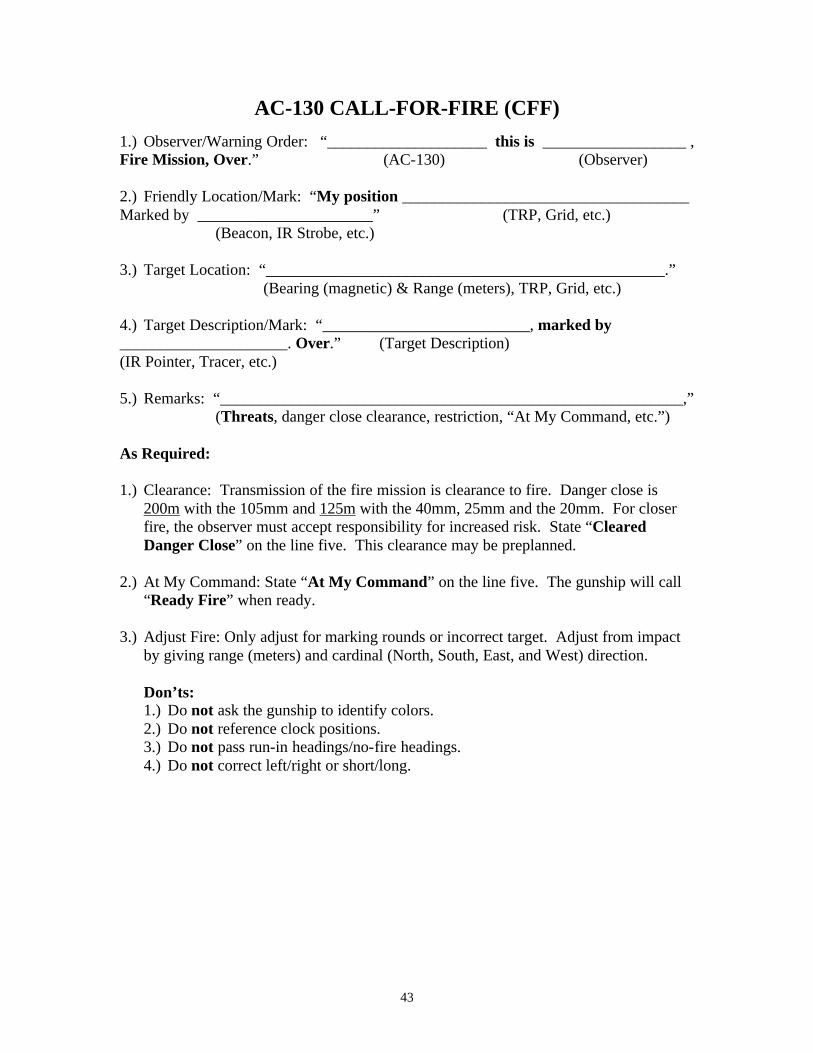
AC-130 CALL-FOR-FIRE (CFF)
1.) Observer/Warning Order: “____________________ this is __________________ , Fire Mission, Over.” (AC-130) (Observer) 2.) Friendly Location/Mark: “My position ____________________________________ Marked by ______________________” (TRP, Grid, etc.)
(Beacon, IR Strobe, etc.) 3.) Target Location: “__________________________________________________.”
(Bearing (magnetic) & Range (meters), TRP, Grid, etc.)
4.) Target Description/Mark: “__________________________, marked by _____________________. Over.” (Target Description) (IR Pointer, Tracer, etc.) 5.) Remarks: “__________________________________________________________,”
(Threats, danger close clearance, restriction, “At My Command, etc.”) As Required: 1.) Clearance: Transmission of the fire mission is clearance to fire. Danger close is
200m with the 105mm and 125m with the 40mm, 25mm and the 20mm. For closer fire, the observer must accept responsibility for increased risk. State “Cleared Danger Close” on the line five. This clearance may be preplanned.
2.) At My Command: State “At My Command” on the line five. The gunship will call
“Ready Fire” when ready. 3.) Adjust Fire: Only adjust for marking rounds or incorrect target. Adjust from impact
by giving range (meters) and cardinal (North, South, East, and West) direction.
Don’ts: 1.) Do not ask the gunship to identify colors. 2.) Do not reference clock positions. 3.) Do not pass run-in headings/no-fire headings. 4.) Do not correct left/right or short/long.
44
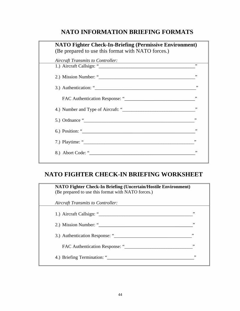
NATO INFORMATION BRIEFING FORMATS
NATO Fighter Check-In-Briefing (Permissive Environment) (Be prepared to use this format with NATO forces.)
Aircraft Transmits to Controller: 1.) Aircraft Callsign: “_________________________________________”
2.) Mission Number: “_________________________________________”
3.) Authentication: “___________________________________________”
FAC Authentication Response: “______________________________”
4.) Number and Type of Aircraft: “_______________________________”
5.) Ordnance “_______________________________________________”
6.) Position: “________________________________________________”
7.) Playtime: “_______________________________________________”
8.) Abort Code: “_____________________________________________”
NATO FIGHTER CHECK-IN BRIEFING WORKSHEET
NATO Fighter Check-In Briefing (Uncertain/Hostile Environment) (Be prepared to use this format with NATO forces.) Aircraft Transmits to Controller:
1.) Aircraft Callsign: “________________________________________”
2.) Mission Number: “________________________________________”
3.) Authentication Response: “_________________________________”
FAC Authentication Response: “_____________________________”
4.) Briefing Termination: “_____________________________________”
45
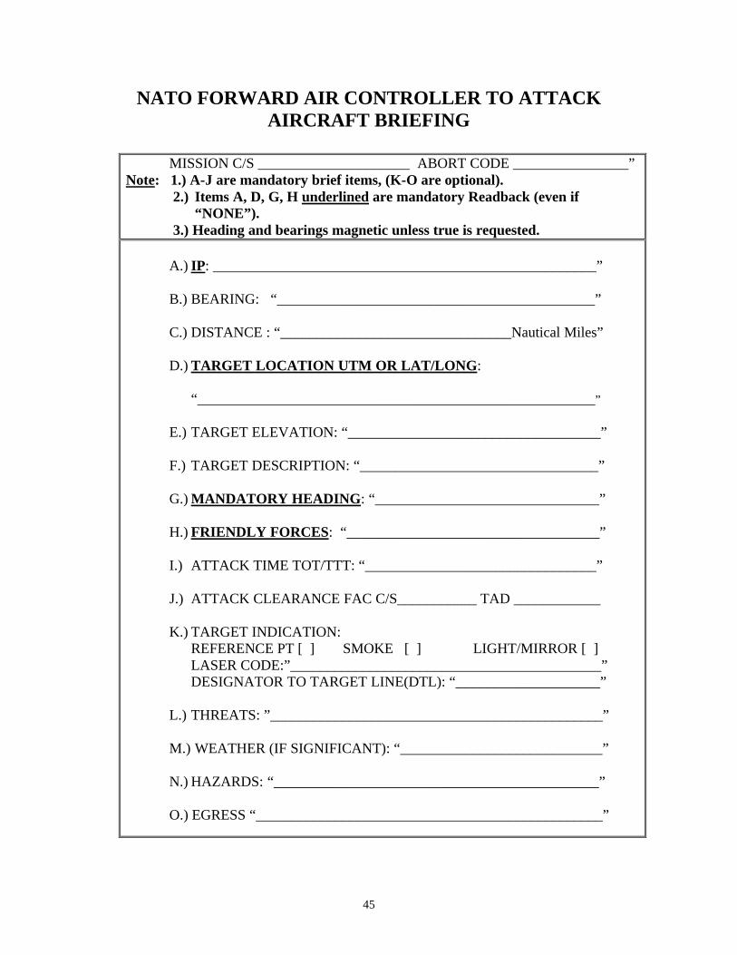
NATO FORWARD AIR CONTROLLER TO ATTACK AIRCRAFT BRIEFING
MISSION C/S _____________________ ABORT CODE ________________”
Note: 1.) A-J are mandatory brief items, (K-O are optional). 2.) Items A, D, G, H underlined are mandatory Readback (even if
“NONE”). 3.) Heading and bearings magnetic unless true is requested.
A.) IP: _____________________________________________________”
B.) BEARING: “____________________________________________”
C.) DISTANCE : “________________________________Nautical Miles”
D.) TARGET LOCATION UTM OR LAT/LONG:
“_______________________________________________________”
E.) TARGET ELEVATION: “___________________________________”
F.) TARGET DESCRIPTION: “_________________________________”
G.) MANDATORY HEADING: “_______________________________”
H.) FRIENDLY FORCES: “___________________________________”
I.) ATTACK TIME TOT/TTT: “________________________________”
J.) ATTACK CLEARANCE FAC C/S___________ TAD ____________
K.) TARGET INDICATION:
REFERENCE PT [ ] SMOKE [ ] LIGHT/MIRROR [ ] LASER CODE:”___________________________________________” DESIGNATOR TO TARGET LINE(DTL): “____________________”
L.) THREATS: ”______________________________________________” M.) WEATHER (IF SIGNIFICANT): “____________________________”
N.) HAZARDS: “_____________________________________________” O.) EGRESS “________________________________________________”
46
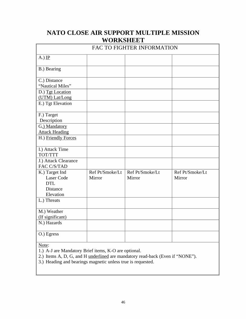
NATO CLOSE AIR SUPPORT MULTIPLE MISSION WORKSHEET
FAC TO FIGHTER INFORMATION
A.) IP
B.) Bearing
C.) Distance “Nautical Miles”
D.) Tgt Location (UTM) Lat/Long
E.) Tgt Elevation
F.) Target Description
G.) Mandatory Attack Heading
H.) Friendly Forces
I.) Attack Time TOT/TTT
J.) Attack Clearance FAC C/S/TAD
K.) Target Ind Laser Code DTL Distance Elevation
Ref Pt/Smoke/Lt Mirror
Ref Pt/Smoke/Lt Mirror
Ref Pt/Smoke/Lt Mirror
L.) Threats
M.) Weather (If significant)
N.) Hazards
O.) Egress
Note: 1.) A-J are Mandatory Brief items, K-O are optional. 2.) Items A, D, G, and H underlined are mandatory read-back (Even if “NONE”). 3.) Heading and bearings magnetic unless true is requested.
47
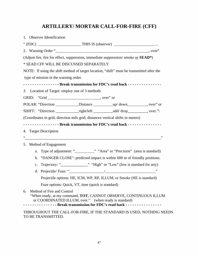
ARTILLERY/ MORTAR CALL-FOR-FIRE (CFF)
1. Observer Identification
“ (FDC) ______________________ THIS IS (observer) _____________________…
2. Warning Order “________________________________________________, over”
(Adjust fire, fire for effect, suppression, immediate suppression/ smoke or SEAD*)
* SEAD CFF WILL BE DISCUSSED SEPARATELY
NOTE: If using the shift method of target location, “shift” must be transmitted after the
type of mission in the warning order.
- - - - - - - - - - - - - - - - Break transmission for FDC’s read back - - - - - - - - - - - - - - -
3. Location of Target: employ one of 3 methods
GRID: “Grid ___________________________, over” or
POLAR: “Direction ____________Distance __________up/ down__________, over” or
SHIFT: “Direction ____________right/left __________add/ drop__________, over.”\
(Coordinates in grid, direction mils grid, distances vertical shifts in meters)
- - - - - - - - - - - - - - - - Break transmission for FDC’s read back - - - - - - - - - - - - - - -
4. Target Description
“______________________________________________________________________”
5. Method of Engagement
a. Type of adjustment: “__________” “Area” or “Precision” (area is standard)
b. “DANGER CLOSE": predicted impact is within 600 m of friendly positions.
c. Trajectory: “______________” “High” or “Low” (low is standard for arty)
d. Projectile/ Fuze: “__________________/__________________________”
Projectile options: HE, ICM, WP, RP, ILLUM, or Smoke (HE is standard)
Fuze options: Quick, VT, time (quick is standard)
6. Method of Fire and Control “When ready, at my command, TOT, CANNOT OBSERVE, CONTINUOUS ILLUM or COORDINATED ILLUM, over.” (when ready is standard) - - - - - - - - - - - - - - - Break transmission for FDC’s read back - - - - - - - - - - - - - - - -
THROUGHOUT THE CALL-FOR-FIRE, IF THE STANDARD IS USED, NOTHING NEEDS TO BE TRANSMITTED.
48
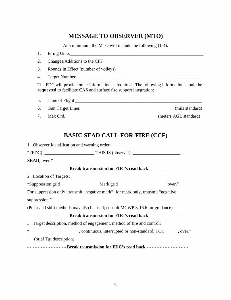
MESSAGE TO OBSERVER (MTO)
At a minimum, the MTO will include the following (1-4):
1. Firing Units___________________________________________________________
2. Changes/Additions to the CFF____________________________________________
3. Rounds in Effect (number of volleys)______________________________________
4. Target Number________________________________________________________
The FDC will provide other information as required. The following information should be requested to facilitate CAS and surface fire support integration:
5. Time of Flight ________________________________________________________
6. Gun Target Lines__________________________________________(mils standard)
7. Max Ord._________________________________________(meters AGL standard)
BASIC SEAD CALL-FOR-FIRE (CCF)
1. Observer Identification and warning order:
“ (FDC) ______________________ THIS IS (observer) _____________________…
SEAD, over.”
- - - - - - - - - - - - - - - - Break transmission for FDC’s read back - - - - - - - - - - - - - - -
2. Location of Targets:
“Suppression grid _________________Mark grid ____________________, over.”
For suppression only, transmit “negative mark”; for mark only, transmit “negative
suppression.”
(Polar and shift methods may also be used; consult MCWP 3-16.6 for guidance)
- - - - - - - - - - - - - - - - Break transmission for FDC’s read back - - - - - - - - - - - - - - -
3. Target description, method of engagement, method of fire and control:
“______________________, continuous, interrupted or non-standard, TOT______, over.”
(brief Tgt description)
- - - - - - - - - - - - - - - Break transmission for FDC’s read back - - - - - - - - - - - - - - - -
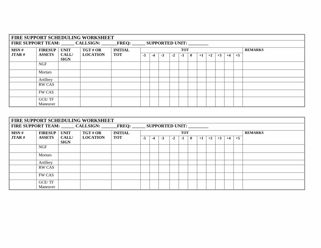
FIRE SUPPORT SCHEDULING WORKSHEET
FIRE SUPPORT TEAM: ______ CALLSIGN: _______FREQ: ______ SUPPORTED UNIT: _________
TOT MSN # JTAR #
FIRESUP ASSETS
UNIT CALL/ SIGN
TGT # OR LOCATION
INITIAL TOT -5 -4 -3 -2 -1 0 +1 +2 +3 +4 +5
REMARKS
NGF
Mortars
Artillery RW CAS
FW CAS
GCE/ TF Maneuver
FIRE SUPPORT SCHEDULING WORKSHEET
FIRE SUPPORT TEAM: ______ CALLSIGN: _______FREQ: ______ SUPPORTED UNIT: _________
TOT MSN # JTAR #
FIRESUP ASSETS
UNIT CALL/ SIGN
TGT # OR LOCATION
INITIAL TOT -5 -4 -3 -2 -1 0 +1 +2 +3 +4 +5
REMARKS
NGF
Mortars
Artillery RW CAS
FW CAS
GCE/ TF Maneuver

50
(This page intentionally left blank.)
51
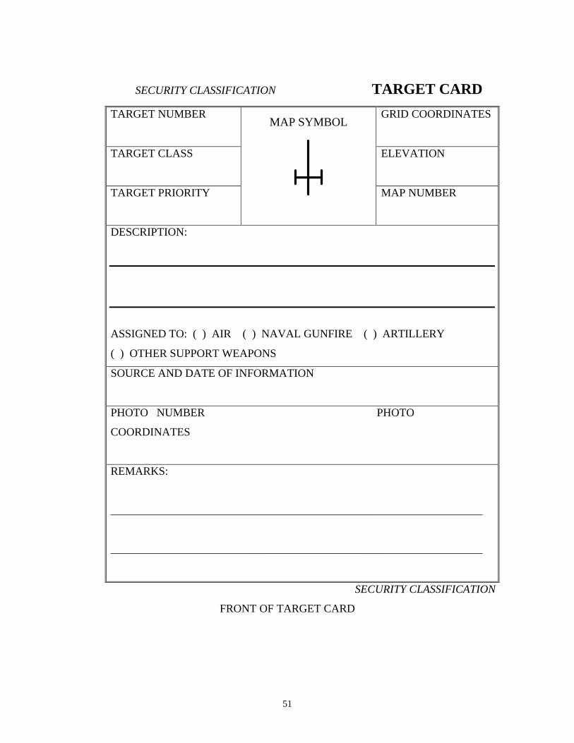
SECURITY CLASSIFICATION TARGET CARD
TARGET NUMBER
GRID COORDINATES
TARGET CLASS
ELEVATION
TARGET PRIORITY
MAP NUMBER
DESCRIPTION:
ASSIGNED TO: ( ) AIR ( ) NAVAL GUNFIRE ( ) ARTILLERY
( ) OTHER SUPPORT WEAPONS
SOURCE AND DATE OF INFORMATION
PHOTO NUMBER PHOTO
COORDINATES
REMARKS:
__________________________________________________________________
__________________________________________________________________
SECURITY CLASSIFICATION
FRONT OF TARGET CARD
MAP SYMBOL
52
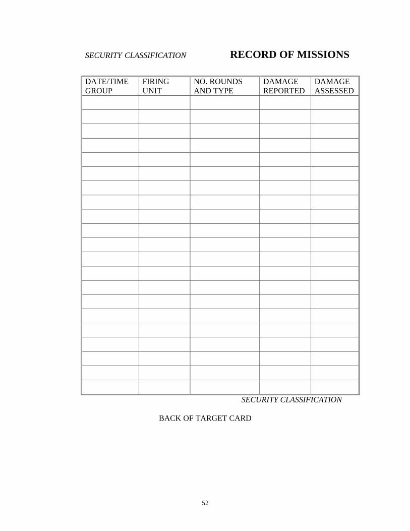
SECURITY CLASSIFICATION RECORD OF MISSIONS
DATE/TIME GROUP
FIRING UNIT
NO. ROUNDS AND TYPE
DAMAGE REPORTED
DAMAGE ASSESSED
SECURITY CLASSIFICATION
BACK OF TARGET CARD
53
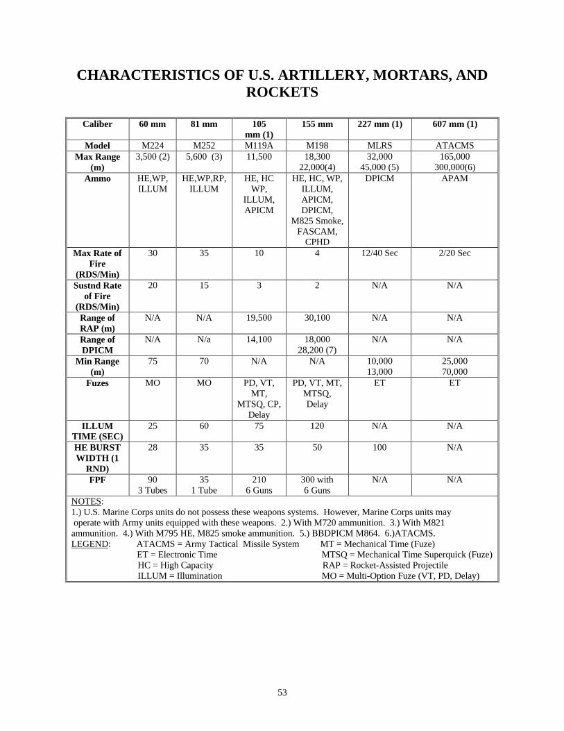
CHARACTERISTICS OF U.S. ARTILLERY, MORTARS, AND ROCKETS
Caliber 60 mm 81 mm 105
mm (1) 155 mm 227 mm (1) 607 mm (1)
Model M224 M252 M119A M198 MLRS ATACMS Max Range
(m) 3,500 (2) 5,600 (3) 11,500 18,300
22,000(4) 32,000
45,000 (5) 165,000
300,000(6) Ammo HE,WP,
ILLUM HE,WP,RP,
ILLUM HE, HC
WP, ILLUM, APICM
HE, HC, WP, ILLUM, APICM, DPICM,
M825 Smoke, FASCAM,
CPHD
DPICM APAM
Max Rate of Fire
(RDS/Min)
30 35 10 4 12/40 Sec 2/20 Sec
Sustnd Rate of Fire
(RDS/Min)
20 15 3 2 N/A N/A
Range of RAP (m)
N/A N/A 19,500 30,100 N/A N/A
Range of DPICM
N/A N/a 14,100 18,000 28,200 (7)
N/A N/A
Min Range (m)
75 70 N/A N/A 10,000 13,000
25,000 70,000
Fuzes MO MO PD, VT, MT,
MTSQ, CP, Delay
PD, VT, MT, MTSQ, Delay
ET ET
ILLUM TIME (SEC)
25 60 75 120 N/A N/A
HE BURST WIDTH (1
RND)
28 35 35 50 100 N/A
FPF 90 3 Tubes
35 1 Tube
210 6 Guns
300 with 6 Guns
N/A N/A
NOTES: 1.) U.S. Marine Corps units do not possess these weapons systems. However, Marine Corps units may operate with Army units equipped with these weapons. 2.) With M720 ammunition. 3.) With M821 ammunition. 4.) With M795 HE, M825 smoke ammunition. 5.) BBDPICM M864. 6.)ATACMS. LEGEND: ATACMS = Army Tactical Missile System MT = Mechanical Time (Fuze)
ET = Electronic Time MTSQ = Mechanical Time Superquick (Fuze) HC = High Capacity RAP = Rocket-Assisted Projectile ILLUM = Illumination MO = Multi-Option Fuze (VT, PD, Delay)
54
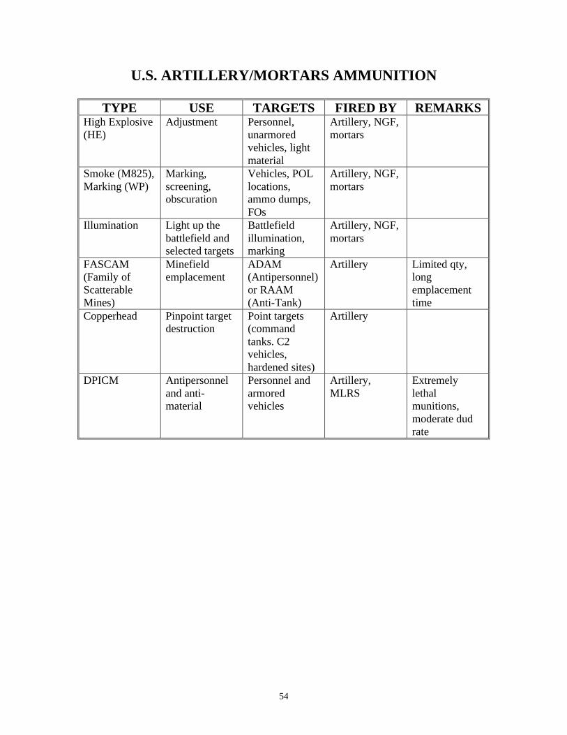
U.S. ARTILLERY/MORTARS AMMUNITION
TYPE USE TARGETS FIRED BY REMARKS High Explosive (HE)
Adjustment Personnel, unarmored vehicles, light material
Artillery, NGF, mortars
Smoke (M825), Marking (WP)
Marking, screening, obscuration
Vehicles, POL locations, ammo dumps, FOs
Artillery, NGF, mortars
Illumination Light up the battlefield and selected targets
Battlefield illumination, marking
Artillery, NGF, mortars
FASCAM (Family of Scatterable Mines)
Minefield emplacement
ADAM (Antipersonnel) or RAAM (Anti-Tank)
Artillery Limited qty, long emplacement time
Copperhead Pinpoint target destruction
Point targets (command tanks. C2 vehicles, hardened sites)
Artillery
DPICM Antipersonnel and anti-material
Personnel and armored vehicles
Artillery, MLRS
Extremely lethal munitions, moderate dud rate
55
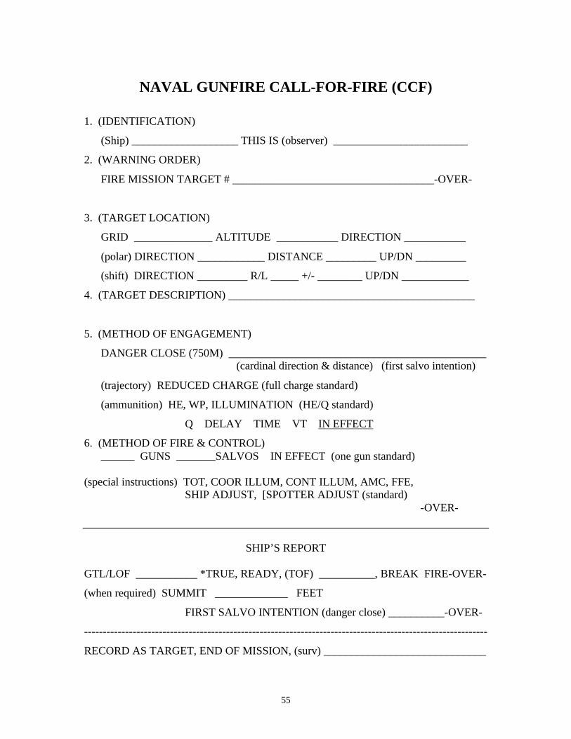
NAVAL GUNFIRE CALL-FOR-FIRE (CCF)
1. (IDENTIFICATION)
(Ship) ___________________ THIS IS (observer) ________________________
2. (WARNING ORDER)
FIRE MISSION TARGET # ____________________________________-OVER-
3. (TARGET LOCATION)
GRID ______________ ALTITUDE ___________ DIRECTION ___________
(polar) DIRECTION ____________ DISTANCE _________ UP/DN _________
(shift) DIRECTION _________ R/L _____ +/- ________ UP/DN ____________
4. (TARGET DESCRIPTION) ____________________________________________
5. (METHOD OF ENGAGEMENT)
DANGER CLOSE (750M) ______________________________________________ (cardinal direction & distance) (first salvo intention)
(trajectory) REDUCED CHARGE (full charge standard)
(ammunition) HE, WP, ILLUMINATION (HE/Q standard)
Q DELAY TIME VT IN EFFECT
6. (METHOD OF FIRE & CONTROL) ______ GUNS _______SALVOS IN EFFECT (one gun standard)
(special instructions) TOT, COOR ILLUM, CONT ILLUM, AMC, FFE,
SHIP ADJUST, [SPOTTER ADJUST (standard) -OVER-
SHIP’S REPORT GTL/LOF ___________ *TRUE, READY, (TOF) __________, BREAK FIRE-OVER-
(when required) SUMMIT _____________ FEET
FIRST SALVO INTENTION (danger close) __________-OVER-
------------------------------------------------------------------------------------------------------------
RECORD AS TARGET, END OF MISSION, (surv) _____________________________
56
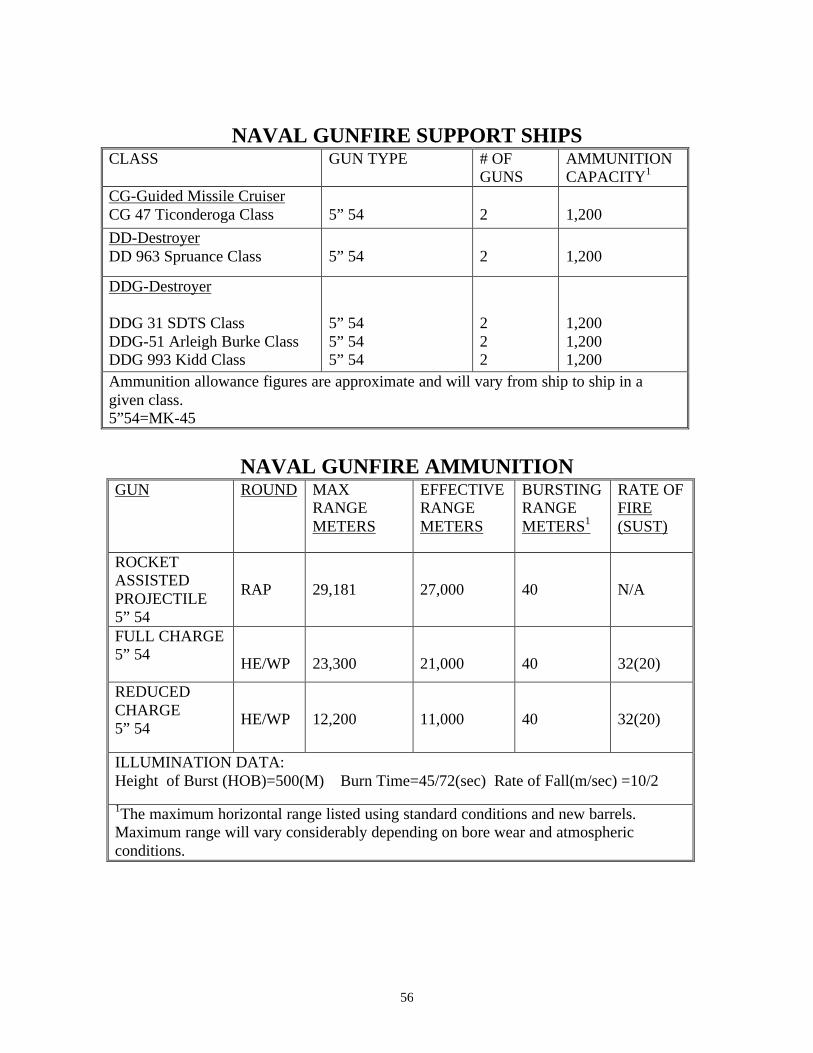
NAVAL GUNFIRE SUPPORT SHIPS CLASS GUN TYPE # OF
GUNS AMMUNITION CAPACITY1
CG-Guided Missile Cruiser CG 47 Ticonderoga Class
5” 54
2
1,200
DD-Destroyer DD 963 Spruance Class
5” 54
2
1,200
DDG-Destroyer DDG 31 SDTS Class DDG-51 Arleigh Burke Class DDG 993 Kidd Class
5” 54 5” 54 5” 54
2 2 2
1,200 1,200 1,200
Ammunition allowance figures are approximate and will vary from ship to ship in a given class. 5”54=MK-45
NAVAL GUNFIRE AMMUNITION
GUN ROUND MAX RANGE METERS
EFFECTIVE RANGE METERS
BURSTING RANGE METERS1
RATE OF FIRE (SUST)
ROCKET ASSISTED PROJECTILE 5” 54
RAP
29,181
27,000
40
N/A
FULL CHARGE 5” 54
HE/WP
23,300
21,000
40
32(20)
REDUCED CHARGE 5” 54
HE/WP
12,200
11,000
40
32(20)
ILLUMINATION DATA: Height of Burst (HOB)=500(M) Burn Time=45/72(sec) Rate of Fall(m/sec) =10/2
1The maximum horizontal range listed using standard conditions and new barrels. Maximum range will vary considerably depending on bore wear and atmospheric conditions.
57
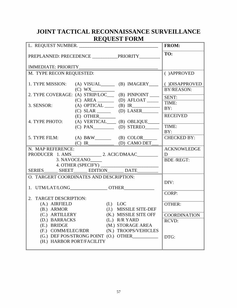
JOINT TACTICAL RECONNAISSANCE SURVEILLANCE REQUEST FORM
FROM: L. REQUEST NUMBER. __________________________________ PREPLANNED: PRECEDENCE ___________PRIORITY_________ IMMEDIATE: PRIORITY__________________________________
TO:
( )APPROVED ( )DISAPPROVED BY/REASON:
SENT: TIME: BY:
RECEIVED
TIME: BY:
M. TYPE RECON REQUESTED: 1. TYPE MISSION: (A) VISUAL______ (B) IMAGERY____
(C) WX__________ 2. TYPE COVERAGE: (A) STRIP/LOC___ (B) PINPOINT ____
(C) AREA _______ (D) AFLOAT _____ 3. SENSOR: (A) OPTICAL ____ (B) IR____________
(C) SLAR ______ (D) LASER_______ (E) OTHER_______
4. TYPE PHOTO: (A) VERTICAL____ (B) OBLIQUE_____ (C) PAN_________ (D) STEREO______
5. TYPE FILM: (A) B&W_______ (B) COLOR______
(C) IR___________ (D) CAMO DET___ CHECKED BY:
ACKNOWLEDGED
N. MAP REFERENCE: PRODUCER 1. AMS_____________ 2. ACIC/DMAAC_________
3. NAVOCEANO_____ 4. OTHER (SPECIFY) _________________________
SERIES______ SHEET______ EDITION_______ DATE_________
BDE /REGT:
DIV: CORP: OTHER: COORDINATION
O. TARGERT COORDINATES AND DESCRIPTION: 1. UTM/LAT/LONG________________ OTHER_____________ 2. TARGET DESCRIPTION:
(A.) AIRFIELD (I.) LOC (B.) ARMOR (J.) MISSILE SITE-DEF (C.) ARTILLERY (K.) MISSILE SITE OFF (D.) BARRACKS (L.) R/R YARD (E.) BRIDGE (M.) STORAGE AREA (F.) COMM/ELEC/RDR (N.) TROOPS/VEHICLES (G.) DEF POS/STRONG POINT (O.) OTHER___________ (H.) HARBOR PORT/FACILITY
RCVD: DTG:
58
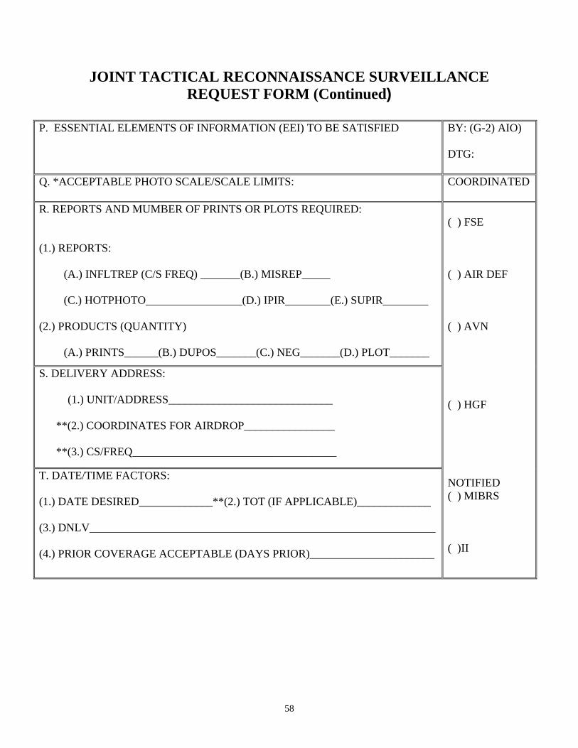
JOINT TACTICAL RECONNAISSANCE SURVEILLANCE REQUEST FORM (Continued)
P. ESSENTIAL ELEMENTS OF INFORMATION (EEI) TO BE SATISFIED BY: (G-2) AIO)
DTG:
Q. *ACCEPTABLE PHOTO SCALE/SCALE LIMITS:
COORDINATED
R. REPORTS AND MUMBER OF PRINTS OR PLOTS REQUIRED:
(1.) REPORTS:
(A.) INFLTREP (C/S FREQ) _______(B.) MISREP_____ (C.) HOTPHOTO_________________(D.) IPIR________(E.) SUPIR________
(2.) PRODUCTS (QUANTITY)
(A.) PRINTS______(B.) DUPOS_______(C.) NEG_______(D.) PLOT_______
S. DELIVERY ADDRESS:
(1.) UNIT/ADDRESS_____________________________ **(2.) COORDINATES FOR AIRDROP________________ **(3.) CS/FREQ____________________________________
T. DATE/TIME FACTORS:
(1.) DATE DESIRED_____________**(2.) TOT (IF APPLICABLE)_____________
(3.) DNLV_____________________________________________________________ (4.) PRIOR COVERAGE ACCEPTABLE (DAYS PRIOR)______________________
( ) FSE ( ) AIR DEF ( ) AVN ( ) HGF NOTIFIED ( ) MIBRS ( )II
59
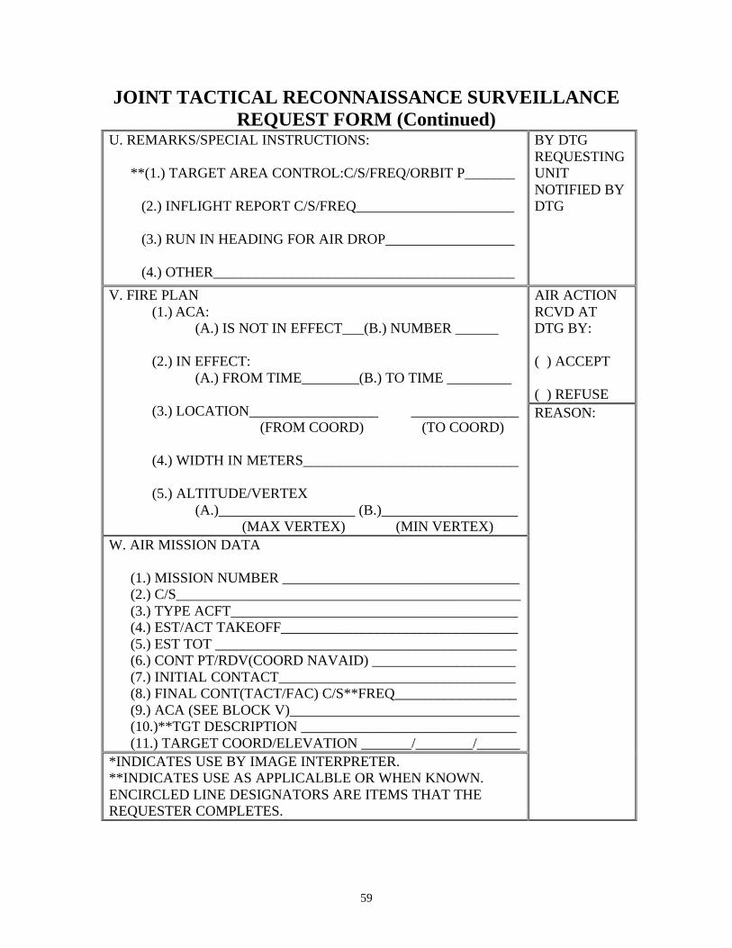
JOINT TACTICAL RECONNAISSANCE SURVEILLANCE REQUEST FORM (Continued)
U. REMARKS/SPECIAL INSTRUCTIONS: **(1.) TARGET AREA CONTROL:C/S/FREQ/ORBIT P_______ (2.) INFLIGHT REPORT C/S/FREQ______________________ (3.) RUN IN HEADING FOR AIR DROP__________________ (4.) OTHER__________________________________________
BY DTG REQUESTING UNIT NOTIFIED BY DTG
AIR ACTION RCVD AT DTG BY: ( ) ACCEPT ( ) REFUSE
V. FIRE PLAN (1.) ACA:
(A.) IS NOT IN EFFECT___(B.) NUMBER ______
(2.) IN EFFECT: (A.) FROM TIME________(B.) TO TIME _________
(3.) LOCATION__________________ _______________
(FROM COORD) (TO COORD) (4.) WIDTH IN METERS______________________________ (5.) ALTITUDE/VERTEX
(A.)___________________ (B.)___________________ (MAX VERTEX) (MIN VERTEX)
W. AIR MISSION DATA (1.) MISSION NUMBER _________________________________ (2.) C/S________________________________________________ (3.) TYPE ACFT________________________________________ (4.) EST/ACT TAKEOFF_________________________________ (5.) EST TOT __________________________________________ (6.) CONT PT/RDV(COORD NAVAID) ____________________ (7.) INITIAL CONTACT_________________________________ (8.) FINAL CONT(TACT/FAC) C/S**FREQ_________________ (9.) ACA (SEE BLOCK V)________________________________ (10.)**TGT DESCRIPTION ______________________________ (11.) TARGET COORD/ELEVATION _______/________/______
*INDICATES USE BY IMAGE INTERPRETER. **INDICATES USE AS APPLICALBLE OR WHEN KNOWN. ENCIRCLED LINE DESIGNATORS ARE ITEMS THAT THE REQUESTER COMPLETES.
REASON:

60
(This page intentionally left blank.)
61
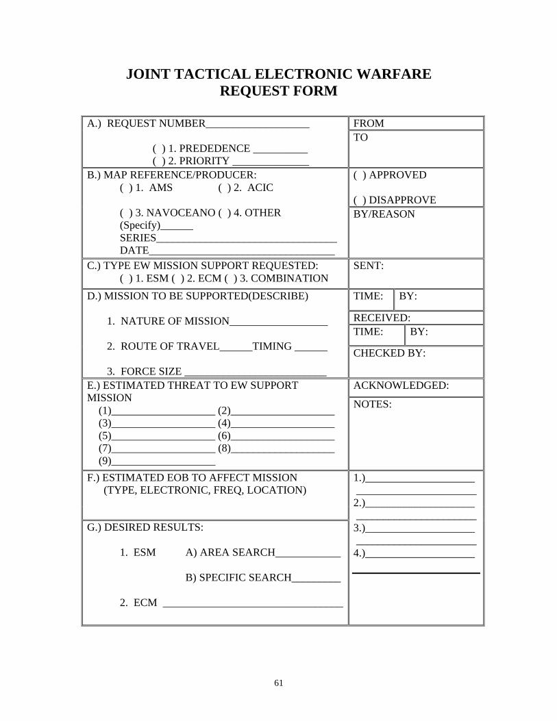
JOINT TACTICAL ELECTRONIC WARFARE REQUEST FORM
FROM A.) REQUEST NUMBER___________________
( ) 1. PREDEDENCE __________ ( ) 2. PRIORITY ______________
TO
( ) APPROVED ( ) DISAPPROVE
B.) MAP REFERENCE/PRODUCER: ( ) 1. AMS ( ) 2. ACIC ( ) 3. NAVOCEANO ( ) 4. OTHER (Specify)______ SERIES_________________________________ DATE__________________________________
BY/REASON
C.) TYPE EW MISSION SUPPORT REQUESTED: ( ) 1. ESM ( ) 2. ECM ( ) 3. COMBINATION
SENT:
TIME: BY:
RECEIVED: TIME: BY:
D.) MISSION TO BE SUPPORTED(DESCRIBE)
1. NATURE OF MISSION__________________
2. ROUTE OF TRAVEL______TIMING ______
3. FORCE SIZE __________________________
CHECKED BY:
ACKNOWLEDGED: E.) ESTIMATED THREAT TO EW SUPPORT MISSION
(1)___________________ (2)___________________ (3)___________________ (4)___________________ (5)___________________ (6)___________________ (7)___________________ (8)___________________ (9)___________________
NOTES:
F.) ESTIMATED EOB TO AFFECT MISSION (TYPE, ELECTRONIC, FREQ, LOCATION)
G.) DESIRED RESULTS:
1. ESM A) AREA SEARCH____________ B) SPECIFIC SEARCH_________
2. ECM _________________________________
1.)____________________ ______________________ 2.)____________________ ______________________ 3.)____________________ ______________________ 4.)____________________
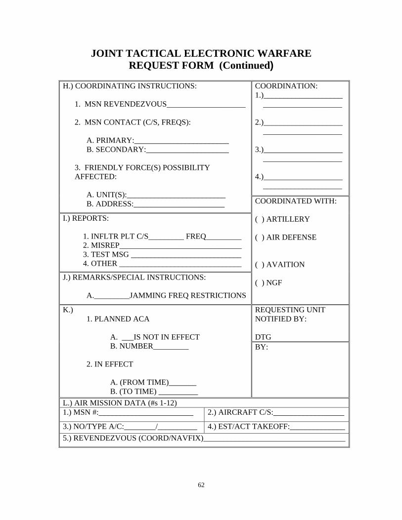
62
JOINT TACTICAL ELECTRONIC WARFARE REQUEST FORM (Continued)
COORDINATION: 1.)____________________ ____________________ 2.)____________________ ____________________ 3.)____________________ ____________________ 4.)____________________ ____________________
H.) COORDINATING INSTRUCTIONS:
1. MSN REVENDEZVOUS____________________
2. MSN CONTACT (C/S, FREQS):
A. PRIMARY:________________________ B. SECONDARY:_____________________
3. FRIENDLY FORCE(S) POSSIBILITY AFFECTED:
A. UNIT(S):_________________________ B. ADDRESS:_______________________
I.) REPORTS:
1. INFLTR PLT C/S_________ FREQ_________ 2. MISREP_______________________________ 3. TEST MSG ____________________________ 4. OTHER _______________________________
J.) REMARKS/SPECIAL INSTRUCTIONS:
A._________JAMMING FREQ RESTRICTIONS
COORDINATED WITH: ( ) ARTILLERY ( ) AIR DEFENSE ( ) AVAITION ( ) NGF
REQUESTING UNIT NOTIFIED BY: DTG
K.) 1. PLANNED ACA
A. ___IS NOT IN EFFECT B. NUMBER_________
2. IN EFFECT
A. (FROM TIME)_______ B. (TO TIME) __________
BY:
L.) AIR MISSION DATA (#s 1-12) 1.) MSN #:________________________ 2.) AIRCRAFT C/S:__________________
3.) NO/TYPE A/C:________/__________ 4.) EST/ACT TAKEOFF:______________
5.) REVENDEZVOUS (COORD/NAVFIX)____________________________________
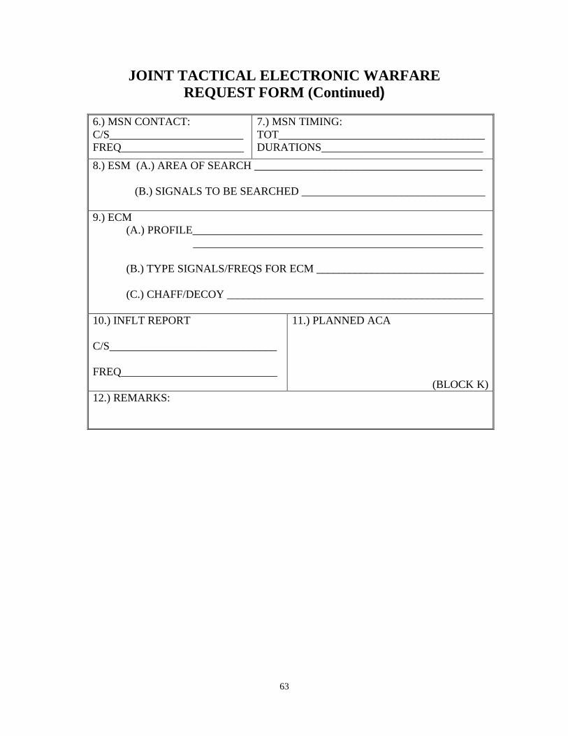
63
JOINT TACTICAL ELECTRONIC WARFARE REQUEST FORM (Continued)
6.) MSN CONTACT: C/S________________________ FREQ______________________
7.) MSN TIMING: TOT_____________________________________ DURATIONS_____________________________
8.) ESM (A.) AREA OF SEARCH _________________________________________
(B.) SIGNALS TO BE SEARCHED _________________________________ 9.) ECM
(A.) PROFILE____________________________________________________ ____________________________________________________
(B.) TYPE SIGNALS/FREQS FOR ECM ______________________________
(C.) CHAFF/DECOY ______________________________________________
10.) INFLT REPORT C/S______________________________ FREQ____________________________
11.) PLANNED ACA
(BLOCK K) 12.) REMARKS:
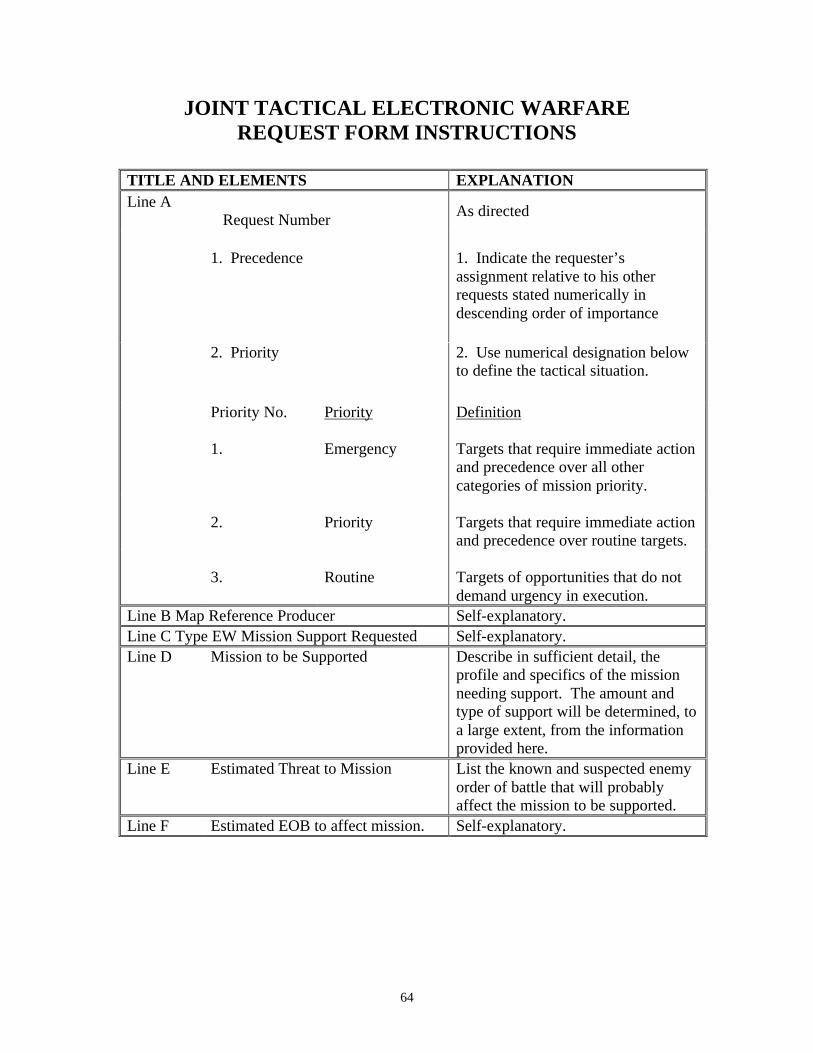
64
JOINT TACTICAL ELECTRONIC WARFARE REQUEST FORM INSTRUCTIONS
TITLE AND ELEMENTS EXPLANATION Line A
Request Number As directed
1. Precedence
1. Indicate the requester’s assignment relative to his other requests stated numerically in descending order of importance
2. Priority 2. Use numerical designation below to define the tactical situation.
Priority No. Priority Definition
1. Emergency
Targets that require immediate action and precedence over all other categories of mission priority.
2.
Priority
Targets that require immediate action and precedence over routine targets.
3.
Routine
Targets of opportunities that do not demand urgency in execution.
Line B Map Reference Producer Self-explanatory. Line C Type EW Mission Support Requested Self-explanatory. Line D Mission to be Supported Describe in sufficient detail, the
profile and specifics of the mission needing support. The amount and type of support will be determined, to a large extent, from the information provided here.
Line E Estimated Threat to Mission List the known and suspected enemy order of battle that will probably affect the mission to be supported.
Line F Estimated EOB to affect mission. Self-explanatory.
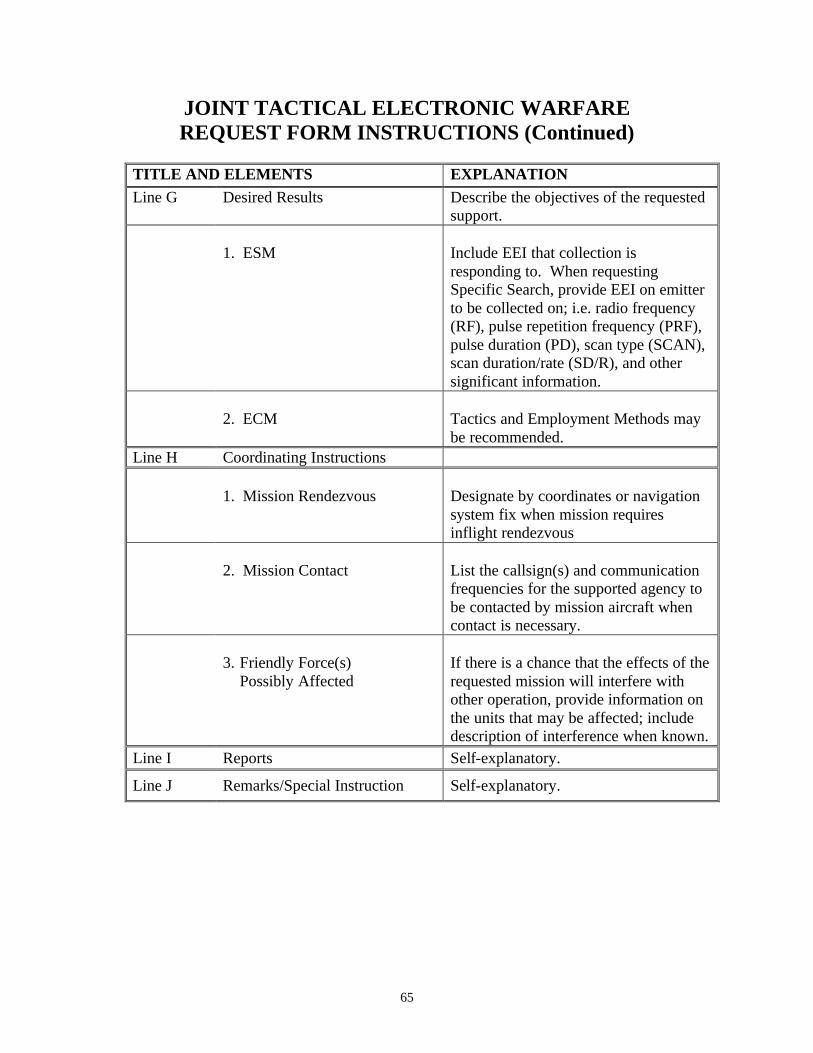
65
JOINT TACTICAL ELECTRONIC WARFARE REQUEST FORM INSTRUCTIONS (Continued)
TITLE AND ELEMENTS EXPLANATION Line G Desired Results Describe the objectives of the requested
support.
1. ESM Include EEI that collection is responding to. When requesting Specific Search, provide EEI on emitter to be collected on; i.e. radio frequency (RF), pulse repetition frequency (PRF), pulse duration (PD), scan type (SCAN), scan duration/rate (SD/R), and other significant information.
2. ECM
Tactics and Employment Methods may be recommended.
Line H Coordinating Instructions
1. Mission Rendezvous Designate by coordinates or navigation system fix when mission requires inflight rendezvous
2. Mission Contact
List the callsign(s) and communication frequencies for the supported agency to be contacted by mission aircraft when contact is necessary.
3. Friendly Force(s)
Possibly Affected
If there is a chance that the effects of the requested mission will interfere with other operation, provide information on the units that may be affected; include description of interference when known.
Line I Reports Self-explanatory.
Line J Remarks/Special Instruction Self-explanatory.
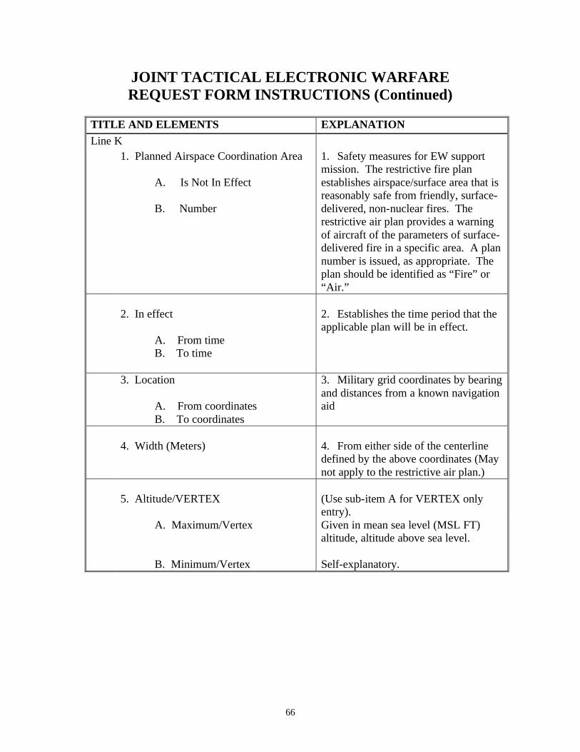
66
JOINT TACTICAL ELECTRONIC WARFARE REQUEST FORM INSTRUCTIONS (Continued)
TITLE AND ELEMENTS EXPLANATION Line K 1. Planned Airspace Coordination Area
A. Is Not In Effect
B. Number
1. Safety measures for EW support mission. The restrictive fire plan establishes airspace/surface area that is reasonably safe from friendly, surface-delivered, non-nuclear fires. The restrictive air plan provides a warning of aircraft of the parameters of surface-delivered fire in a specific area. A plan number is issued, as appropriate. The plan should be identified as “Fire” or “Air.”
2. In effect
A. From time B. To time
2. Establishes the time period that the applicable plan will be in effect.
3. Location
A. From coordinates B. To coordinates
3. Military grid coordinates by bearing and distances from a known navigation aid
4. Width (Meters)
4. From either side of the centerline defined by the above coordinates (May not apply to the restrictive air plan.)
5. Altitude/VERTEX
(Use sub-item A for VERTEX only entry).
A. Maximum/Vertex
B. Minimum/Vertex
Given in mean sea level (MSL FT) altitude, altitude above sea level. Self-explanatory.
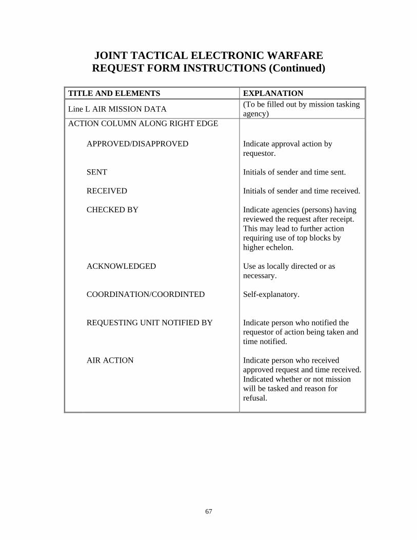
67
JOINT TACTICAL ELECTRONIC WARFARE REQUEST FORM INSTRUCTIONS (Continued)
TITLE AND ELEMENTS EXPLANATION
Line L AIR MISSION DATA (To be filled out by mission tasking agency)
ACTION COLUMN ALONG RIGHT EDGE
APPROVED/DISAPPROVED SENT RECEIVED CHECKED BY ACKNOWLEDGED COORDINATION/COORDINTED REQUESTING UNIT NOTIFIED BY AIR ACTION
Indicate approval action by requestor. Initials of sender and time sent. Initials of sender and time received. Indicate agencies (persons) having reviewed the request after receipt. This may lead to further action requiring use of top blocks by higher echelon. Use as locally directed or as necessary. Self-explanatory. Indicate person who notified the requestor of action being taken and time notified. Indicate person who received approved request and time received. Indicated whether or not mission will be tasked and reason for refusal.

68
(This page intentionally left blank.)
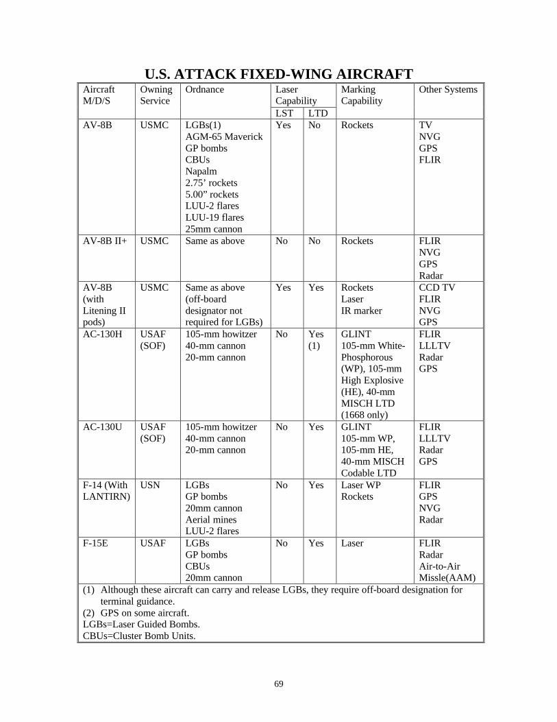
69
U.S. ATTACK FIXED-WING AIRCRAFT Laser Capability
Aircraft M/D/S
Owning Service
Ordnance
LST LTD
Marking Capability
Other Systems
AV-8B USMC LGBs(1) AGM-65 Maverick GP bombs CBUs Napalm 2.75’ rockets 5.00” rockets LUU-2 flares LUU-19 flares 25mm cannon
Yes No Rockets TV NVG GPS FLIR
AV-8B II+
USMC Same as above No No Rockets FLIR NVG GPS Radar
AV-8B (with Litening II pods)
USMC Same as above (off-board designator not required for LGBs)
Yes Yes Rockets Laser IR marker
CCD TV FLIR NVG GPS
AC-130H USAF (SOF)
105-mm howitzer 40-mm cannon 20-mm cannon
No Yes (1)
GLINT 105-mm White-Phosphorous (WP), 105-mm High Explosive (HE), 40-mm MISCH LTD (1668 only)
FLIR LLLTV Radar GPS
AC-130U USAF (SOF)
105-mm howitzer 40-mm cannon 20-mm cannon
No Yes GLINT 105-mm WP, 105-mm HE, 40-mm MISCH Codable LTD
FLIR LLLTV Radar GPS
F-14 (With LANTIRN)
USN LGBs GP bombs 20mm cannon Aerial mines LUU-2 flares
No Yes Laser WP Rockets
FLIR GPS NVG Radar
F-15E USAF LGBs GP bombs CBUs 20mm cannon
No Yes Laser FLIR Radar Air-to-Air Missle(AAM)
(1) Although these aircraft can carry and release LGBs, they require off-board designation for terminal guidance.
(2) GPS on some aircraft. LGBs=Laser Guided Bombs. CBUs=Cluster Bomb Units.

70
U.S. ATTACK FIXED-WING AIRCRAFT (Continued)
Laser Capability
Aircraft M/D/S
Owning Service
Ordnance
LST LTD
Marking Capability
Other Systems
F-16 (without LANTIRN)
USAF AGM-65 Maverick LGBs (1) GP bombs CBUs 20mm cannon
No No WP rockets Radar GPSs (2)
F-16 C/D (with LANTIRN)
USAF AGM-65 Maverick LGBs GP bombs CBUs 20mm cannon
No Yes Laser WP rockets HE rockets
FLIR GPS NVG Radar
F/A-18 USN USMC
LGBs AGM-65 Maverick AGM-62 Walleye AGM-84 SLAM AGM-88 HARM JDAM JSOW GP bombs CBUs Aerial mines LUU-2 flares 2.75’ rockets 5.00” rockets 20mm cannon
Yes Yes Laser WP rockets HE rockets
FLIR GPS NVG Radar IR Pointer
(1.) Although these aircraft can carry and release LGB’s, they require off-board designation for terminal guidance.
(2) GPS on some aircraft. LGBs=Laser Guided Bombs. CBUs=Cluster Bomb Units.

71
U.S. ATTACK ROTARY-WING AIRCRAFT
Laser Capability
Marking Capability
Other Systems
A/C M/D/S
Owning Service
Ordnance Max Range (m)
Max RDS
LST LTD AH-1W USMC BGM-71 (TOW)
AGM-114 5.0” rockets 2.75”rockets 20-mm cannon
3750 8000 7200 6-7500 1500
8 8 8 76 750
No Yes Laser Rockets
FLIR NVG GPS IR
Pointer AH-64A USA AGM-114L
2.75”rockets 30-mm cannon
8000 6-7500 3000
16 76 1200
Yes Yes (1)
Laser Rockets
FLIR NVG
AH-64D
(including Longbow)
USA AGM-114L 2.75”rockets 30-mm cannon
8000 6-7500 3000
16 76 1200
Yes Yes (1)
Laser Rockets
FLIR NVG GPS
IDM (1) Radar
UH-1N USMC 2.75” rockets .50 cal machinegun 7.62-mm (GAU-17)
6-7500 1830 1000
76 500 5000
No No Rockets FLIR NVG GPS
Oh-58D (Kiowa Warrior)
USA AGM-114L Hellfire 2.75”rockets .50 cal machine gun
8000 6-7500 1830
16 76 500
Yes Yes Laser Rockets
FLIR NVG
(1) The AH64 helicopters cannot designate laser codes 1711 to 1788. (2) The AH-1W can designate codes 1111-1488, but has max effectiveness from 1111-1178. IMD=Improved Data Modem.
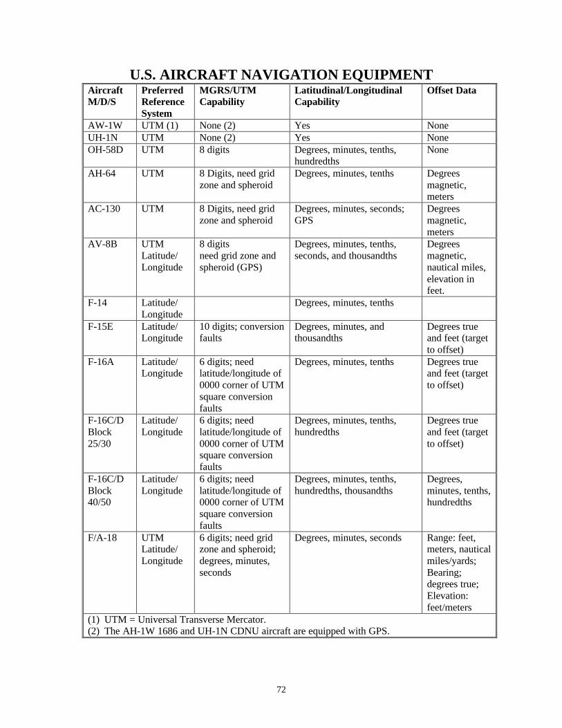
72
U.S. AIRCRAFT NAVIGATION EQUIPMENT Aircraft M/D/S
Preferred Reference System
MGRS/UTM Capability
Latitudinal/Longitudinal Capability
Offset Data
AW-1W UTM (1) None (2) Yes None UH-1N UTM None (2) Yes None OH-58D UTM 8 digits Degrees, minutes, tenths,
hundredths None
AH-64 UTM 8 Digits, need grid zone and spheroid
Degrees, minutes, tenths Degrees magnetic, meters
AC-130 UTM 8 Digits, need grid zone and spheroid
Degrees, minutes, seconds; GPS
Degrees magnetic, meters
AV-8B UTM Latitude/ Longitude
8 digits need grid zone and spheroid (GPS)
Degrees, minutes, tenths, seconds, and thousandths
Degrees magnetic, nautical miles, elevation in feet.
F-14 Latitude/ Longitude
Degrees, minutes, tenths
F-15E Latitude/ Longitude
10 digits; conversion faults
Degrees, minutes, and thousandths
Degrees true and feet (target to offset)
F-16A Latitude/ Longitude
6 digits; need latitude/longitude of 0000 corner of UTM square conversion faults
Degrees, minutes, tenths Degrees true and feet (target to offset)
F-16C/D Block 25/30
Latitude/ Longitude
6 digits; need latitude/longitude of 0000 corner of UTM square conversion faults
Degrees, minutes, tenths, hundredths
Degrees true and feet (target to offset)
F-16C/D Block 40/50
Latitude/ Longitude
6 digits; need latitude/longitude of 0000 corner of UTM square conversion faults
Degrees, minutes, tenths, hundredths, thousandths
Degrees, minutes, tenths, hundredths
F/A-18 UTM Latitude/ Longitude
6 digits; need grid zone and spheroid; degrees, minutes, seconds
Degrees, minutes, seconds Range: feet, meters, nautical miles/yards; Bearing; degrees true; Elevation: feet/meters
(1) UTM = Universal Transverse Mercator. (2) The AH-1W 1686 and UH-1N CDNU aircraft are equipped with GPS.
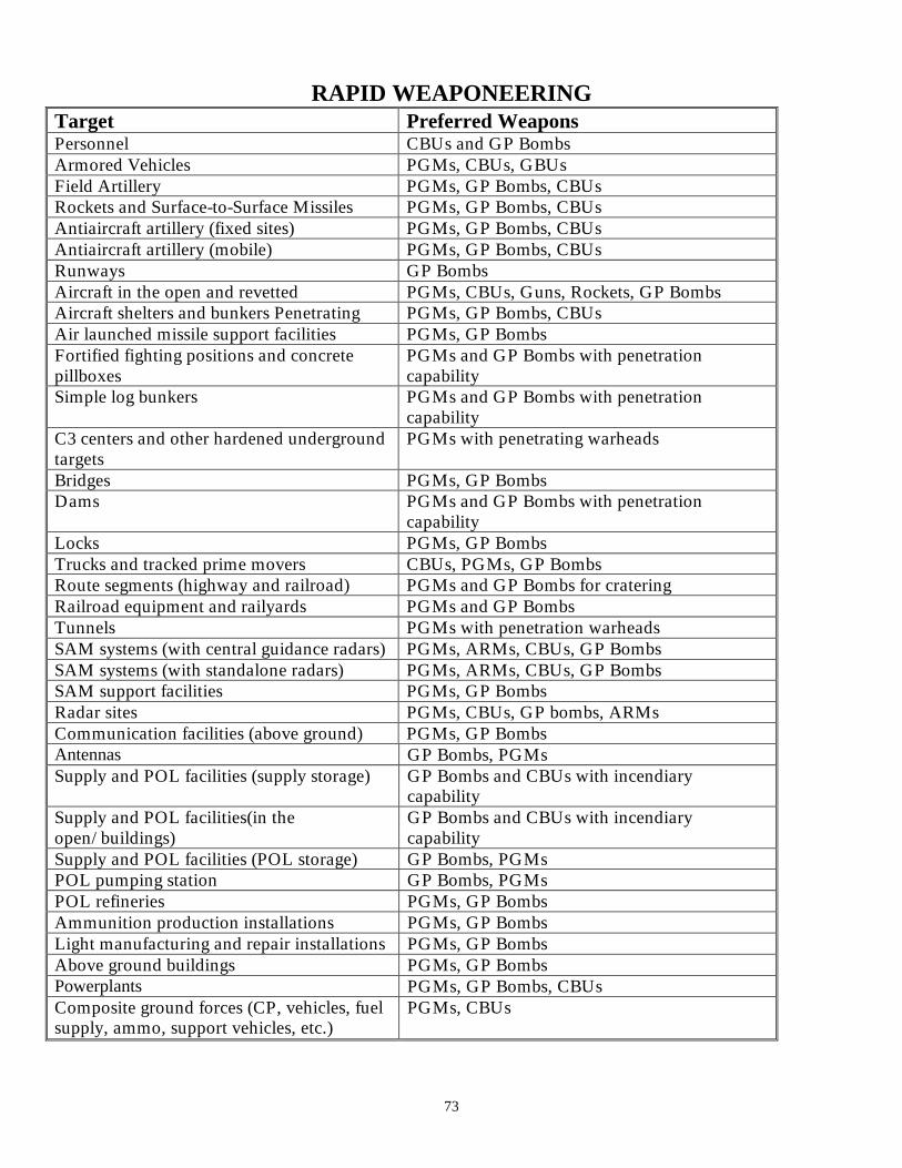
73
RAPID WEAPONEERING Target Preferred Weapons Personnel CBUs and GP Bombs Armored Vehicles PGMs, CBUs, GBUs Field Artillery PGMs, GP Bombs, CBUs Rockets and Surface-to-Surface Missiles PGMs, GP Bombs, CBUs Antiaircraft artillery (fixed sites) PGMs, GP Bombs, CBUs Antiaircraft artillery (mobile) PGMs, GP Bombs, CBUs Runways GP Bombs Aircraft in the open and revetted PGMs, CBUs, Guns, Rockets, GP Bombs Aircraft shelters and bunkers Penetrating PGMs, GP Bombs, CBUs Air launched missile support facilities PGMs, GP Bombs Fortified fighting positions and concrete pillboxes
PGMs and GP Bombs with penetration capability
Simple log bunkers PGMs and GP Bombs with penetration capability
C3 centers and other hardened underground targets
PGMs with penetrating warheads
Bridges PGMs, GP Bombs Dams PGMs and GP Bombs with penetration
capability Locks PGMs, GP Bombs Trucks and tracked prime movers CBUs, PGMs, GP Bombs Route segments (highway and railroad) PGMs and GP Bombs for cratering Railroad equipment and railyards PGMs and GP Bombs Tunnels PGMs with penetration warheads SAM systems (with central guidance radars) PGMs, ARMs, CBUs, GP Bombs SAM systems (with standalone radars) PGMs, ARMs, CBUs, GP Bombs SAM support facilities PGMs, GP Bombs Radar sites PGMs, CBUs, GP bombs, ARMs Communication facilities (above ground) PGMs, GP Bombs Antennas GP Bombs, PGMs Supply and POL facilities (supply storage) GP Bombs and CBUs with incendiary
capability Supply and POL facilities(in the open/buildings)
GP Bombs and CBUs with incendiary capability
Supply and POL facilities (POL storage) GP Bombs, PGMs POL pumping station GP Bombs, PGMs POL refineries PGMs, GP Bombs Ammunition production installations PGMs, GP Bombs Light manufacturing and repair installations PGMs, GP Bombs Above ground buildings PGMs, GP Bombs Powerplants PGMs, GP Bombs, CBUs Composite ground forces (CP, vehicles, fuel supply, ammo, support vehicles, etc.)
PGMs, CBUs
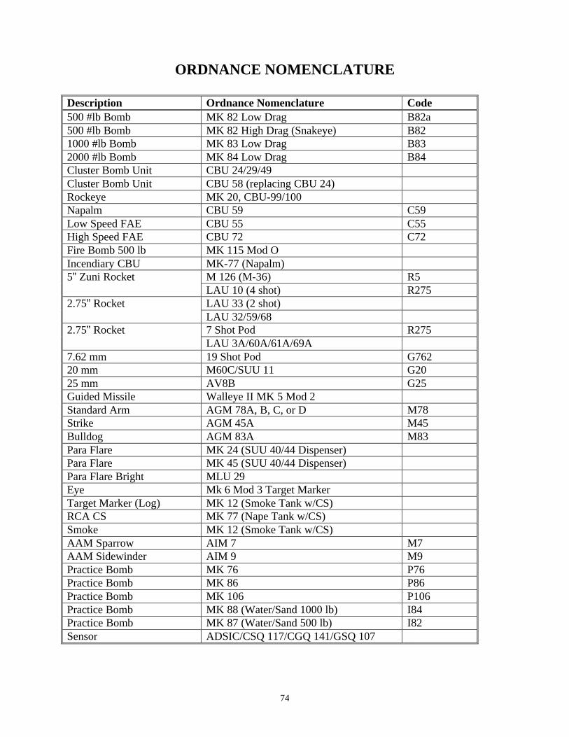
74
ORDNANCE NOMENCLATURE
Description Ordnance Nomenclature Code 500 #lb Bomb MK 82 Low Drag B82a 500 #lb Bomb MK 82 High Drag (Snakeye) B82 1000 #lb Bomb MK 83 Low Drag B83 2000 #lb Bomb MK 84 Low Drag B84 Cluster Bomb Unit CBU 24/29/49 Cluster Bomb Unit CBU 58 (replacing CBU 24) Rockeye MK 20, CBU-99/100 Napalm CBU 59 C59 Low Speed FAE CBU 55 C55 High Speed FAE CBU 72 C72 Fire Bomb 500 lb MK 115 Mod O Incendiary CBU MK-77 (Napalm)
M 126 (M-36) R5 5” Zuni Rocket LAU 10 (4 shot) R275 LAU 33 (2 shot) 2.75” Rocket LAU 32/59/68 7 Shot Pod R275 2.75” Rocket LAU 3A/60A/61A/69A
7.62 mm 19 Shot Pod G762 20 mm M60C/SUU 11 G20 25 mm AV8B G25 Guided Missile Walleye II MK 5 Mod 2 Standard Arm AGM 78A, B, C, or D M78 Strike AGM 45A M45 Bulldog AGM 83A M83 Para Flare MK 24 (SUU 40/44 Dispenser) Para Flare MK 45 (SUU 40/44 Dispenser) Para Flare Bright MLU 29 Eye Mk 6 Mod 3 Target Marker Target Marker (Log) MK 12 (Smoke Tank w/CS) RCA CS MK 77 (Nape Tank w/CS) Smoke MK 12 (Smoke Tank w/CS) AAM Sparrow AIM 7 M7 AAM Sidewinder AIM 9 M9 Practice Bomb MK 76 P76 Practice Bomb MK 86 P86 Practice Bomb MK 106 P106 Practice Bomb MK 88 (Water/Sand 1000 lb) I84 Practice Bomb MK 87 (Water/Sand 500 lb) I82 Sensor ADSIC/CSQ 117/CGQ 141/GSQ 107
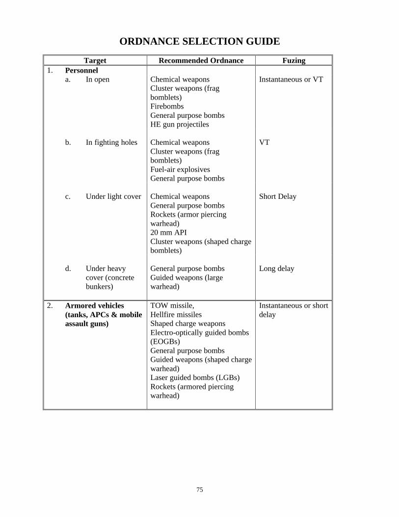
75
ORDNANCE SELECTION GUIDE
Target Recommended Ordnance Fuzing 1. Personnel a. In open Chemical weapons
Cluster weapons (frag bomblets) Firebombs General purpose bombs HE gun projectiles
Instantaneous or VT
b.
In fighting holes
Chemical weapons Cluster weapons (frag bomblets) Fuel-air explosives General purpose bombs
VT
c.
Under light cover
Chemical weapons General purpose bombs Rockets (armor piercing warhead) 20 mm API Cluster weapons (shaped charge bomblets)
Short Delay
d.
Under heavy cover (concrete bunkers)
General purpose bombs Guided weapons (large warhead)
Long delay
2. Armored vehicles (tanks, APCs & mobile assault guns)
TOW missile, Hellfire missiles Shaped charge weapons Electro-optically guided bombs (EOGBs) General purpose bombs Guided weapons (shaped charge warhead) Laser guided bombs (LGBs) Rockets (armored piercing warhead)
Instantaneous or short delay

76
ORDNANCE SELECTION GUIDE (Continued)
Target Recommended Ordnance Fuzing 3. Field Artillery
a. In open
-Cluster weapons (frag and shaped charge bomblets)
-Electro-optically guided bombs (EOGBs)
-General purpose bombs -Guided weapons (large shaped charge warhead)
Proximity, Instantaneous, or Short Delay
b.
In revetments
-Cluster weapons (shape charge bomblets)
-Electro-optically guided Bombs (EOGBs)
-General purpose bombs -Guided weapons (large shaped charge warhead)
Instantaneous or VT
c.
In covered positions
-General purpose bombs -Guided weapons (large warhead)
Delay
4. Antiaircraft Artillery
a. Automatic
Same as 3 with the following additions:
-Firebombs -20 mm HEI
b.
Self-Propelled
Same as 2
5. Rocket Launchers -Cluster weapons (shaped charge bomblets)
-General purpose bombs -Guided weapons (large warhead)
Instantaneous or VT

77
ORDNANCE SELECTION GUIDE (Continued)
Target Recommended Ordnance Fuzing 6. Missile Sites
a. Surface-to-air missiles
-Anti-radiation missiles Followed by cluster weapons (frag and shaped charge bomblets) -Retarded bombs -General purpose bombs
Instantaneous, or VT
b.
Surface-to-surface missiles,
Same as 2 with the following additions:
Instantaneous or VT
Liquid-fuel missiles
-Cluster weapons followed by -Incendiary weapons or Firebombs -General Purpose Bombs
Instantaneous or VT
Solid-fuel missiles
-Cluster Weapons (frag or Shaped charged bomblets) - Electro-optically guided bombs (EOGBs) -General purpose bombs -Laser guided bombs(LGBs)
Instantaneous or VT
7.
Radar Installations
-Antiradiation missiles, -Cluster weapons (frag or Shaped charged bomblets) - Electro-optically guided bombs (EOGBs), -Laser guided bombs (LGBs) -Firebombs, -General purpose bombs, -20mm cannons, -Fuel air explosive (FAE)
Instantaneous or VT
8.
Field Fortifications
-General purpose bombs -Guided weapons (warhead 190 lbs)
Delay
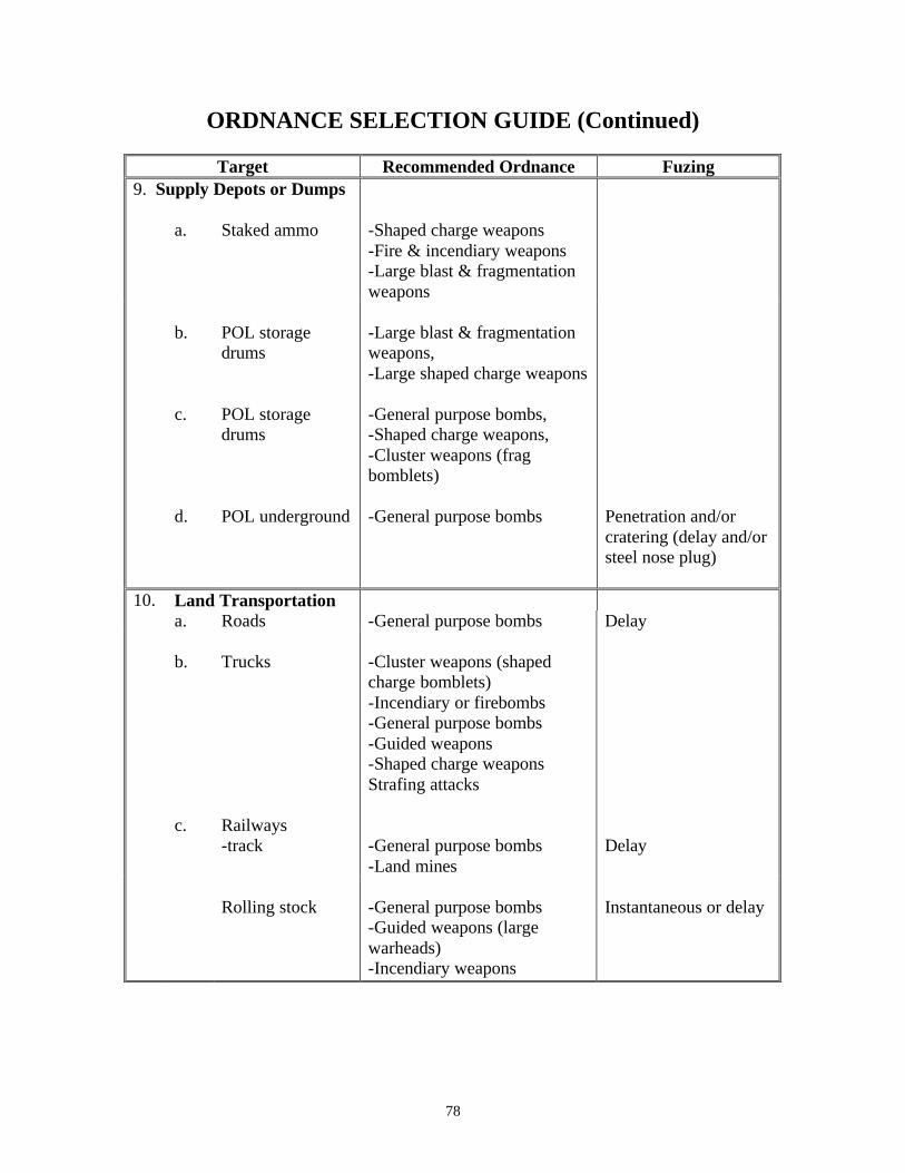
78
ORDNANCE SELECTION GUIDE (Continued)
Target Recommended Ordnance Fuzing 9. Supply Depots or Dumps
a. Staked ammo
-Shaped charge weapons -Fire & incendiary weapons -Large blast & fragmentation weapons
b.
POL storage drums
-Large blast & fragmentation weapons, -Large shaped charge weapons
c.
POL storage drums
-General purpose bombs, -Shaped charge weapons, -Cluster weapons (frag bomblets)
d.
POL underground
-General purpose bombs
Penetration and/or cratering (delay and/or steel nose plug)
10. Land Transportation a. Roads -General purpose bombs Delay
b. Trucks
-Cluster weapons (shaped charge bomblets) -Incendiary or firebombs -General purpose bombs -Guided weapons -Shaped charge weapons Strafing attacks
c.
Railways -track
-General purpose bombs -Land mines
Delay
Rolling stock
-General purpose bombs -Guided weapons (large warheads) -Incendiary weapons
Instantaneous or delay

79
ORDNANCE SELECTION GUIDE (Continued)
Target Recommended Ordnance Fuzing
Locomotives -Cluster weapons (shaped charge bomblets)
-General purpose bombs -Guided weapons (large warheads) -Projectiles & rockets
ORDNANCE “QUICK” REFERENCE GUIDE Family Types of Ordnance
Mk-52 Mk-55
Aerial mines Mk-52
Mk-56 AGM-122 Sidearm Anti-radiation missiles (ARMs) AGM-88 HARM Mk-20 Rockeye CBU-78 Gator
CBUs
AGM-154A/B JSOW (cluster versions) GP bombs MK 82, 83, 84
FAE Incendiary NAPALM/MK-77 AGM-65 IR & Laser Maverick AGM-84D Harpoon AGM-84E SLAM AGM-114 Hellfire AGM-154A/B/C JSOW (C model is unitary version) BGM-71 TOW CALCM GBU 10, 12, 16, 24
Precision guided munitions (PGM)
GBU-31 JDAM

80
(This page intentionally left blank.)

81
RISK-ESTIMATE DISTANCES FOR AIRCRAFT DELIVERED ORDNANCE (Combat Only)
WARNING: RISK-ESTIMATE DISTANCES ARE FOR COMBAT USE AND ARE NOT MINIMUM SAFE DISTANCES FOR PEACETIME TRAINING.
See JMEMS, appropriate Service or Command guidance, or FM 90-20/FMFRP 2-72/ACCP 50-28/USAFEP 50-9/PACAFP 50-28/CINCLANTFLTINST 3330.5 ("J-FIRE") for peacetime restrictions.
Risk-Estimate Dist (m)
Item Description
10% PI
0.1% PI
MK-82 LD 500-lb bomb 250 425
MK-82 HD 500-lb bomb(retarded) 100 375
MK-82 LGB 500-lb bomb(GBU-12) 250 425 (1)
MK-83 HD/LD 1000-lb bomb 275 475 MK-83 LGB 1000-lb bomb(GBU) 275(1) 475 (1)
MK-84 HD/LD 2000-lb bomb 325 500 MK-84 LGB 2000-lb bomb(GBU-10/24) 225(1) 500(1)
MK-20(2) Rockeye (antiarm or CBU) 150 225
MK-77 500-lb napalm(FAE) 100 150
CBU-55/77(2) Fuel-air explosive (FAE) (1) (1)
CBU-52(2) CBUs (All Types) 275 450
CBU-58/71(2,3) CBUs (All Types) 350 525
CBU-87(2) CBUs (All Types) 175 275
CBU-89(3) CBUs (All Types) 175 275
2.75 FFAR Rocket with various warheads 160 200
5.00 FFAR Zuni with various warheads 150 200
SUU-11 7.62mm mini-gun M-4,M-12, SUU-23,M-61 20mm gattling gun 100 150
GAU-12 25mm gun 100 150 GPU-5A, GAU-8 30mm gattling gun 100 150
AGM-65 (4) Maverick (TV, IIR, laser guided bomb)
25 100
MK-1MK-21 Walleye II (2400-lb TV guided bomb)
275 500
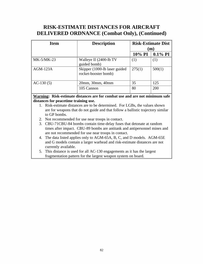
82
RISK-ESTIMATE DISTANCES FOR AIRCRAFT DELIVERED ORDNANCE (Combat Only), (Continued)
Risk-Estimate Dist (m)
Item Description
10% PI 0.1% PI MK-5/MK-23 Walleye II (2400-lb TV
guided bomb) (1) (1)
AGM-123A Skipper (1000-lb laser guided rocket-booster bomb)
275(1) 500(1)
20mm, 30mm, 40mm 35 125 AC-130 (5) 105 Cannon 80 200
Warning: Risk-estimate distances are for combat use and are not minimum safe distances for peacetime training use.
1. Risk-estimate distances are to be determined. For LGBs, the values shown are for weapons that do not guide and that follow a ballistic trajectory similar to GP bombs.
2. Not recommended for use near troops in contact. 3. CBU-71CBU-84 bombs contain time-delay fuses that detonate at random
times after impact. CBU-89 bombs are antitank and antipersonnel mines and are not recommended for use near troops in contact.
4. The data listed applies only to AGM-65A, B, C, and D models. AGM-65E and G models contain a larger warhead and risk-estimate distances are not currently available.
5. This distance is used for all AC-130 engagements as it has the largest fragmentation pattern for the largest weapon system on board.
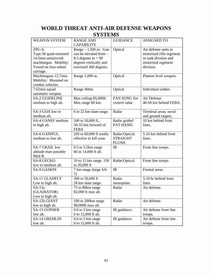
83
WORLD THREAT ANTI-AIR DEFENSE WEAPONS SYSTEMS
WEAPON SYSTEM RANGE AND CAPABILITY
GUIDANCE ASSIGNED TO
ZPU-4, Type 56 quad-mounted 14.5mm antiaircraft machinegun. Mobility: Towed on four-wheel carriage.
Range – 1,500 m. Gun can be elevated from –8.5 degrees to + 90 degrees vertically and traversed 360 degrees.
Optical Air defense units in motorized rifle regiment or tank division and motorized regiment division.
Machineguns 12.7mm. Mobility: Mounted on combat vehicles.
Range 1,000 m. Optical Platoon level weapon.
7.62mm squad automatic weapon.
Range 460m. Optical Individual soldier.
SA-2 GUIDELINE medium to high alt.
Max ceiling 85,000ft Max range 60 km.
FAN SONG fire control radar
Air Defense 40-50 km behind FEBA.
SA-3 GOA low to medium alt.
6 to 22 km slant range. Radar Terminal areas, naval and ground targets.
SA-4 GANEF medium to high alt.
500 to 50,000 ft., 50-55 km forward of FEBA
Radar guided PAT HAND.
10 km behind front lines.
SA-6 GAINFUL medium to low alt.
250 to 60,000 ft totally effective in kill zone.
Radar/Optical. STRAIGHT FLUSH.
5-10 km behind front lines.
SA-7 GRAIL low altitude man portable Mod B.
0.5 to 5.5km range 60 to 14,000 ft alt.
IR Front line troops.
SA-8 GECKO low to medium alt.
10 to 15 km range. 150 to 20,000 ft
Radar/Optical Front line troops.
SA-9 GASKIN
7 km range (large SA-7)
IR Frontal areas.
SA-11 GLADFLY Low to high alt.
300 to 56,000 ft 28 km slant range
Radar monopulse.
5-10 hr behind front lines.
SA-12a (GLADIATOR) Low to high alt.
75 to 80km range 82,000 ft max alt.
Radar Air defense.
SA-12b GIANT low to high alt.
100 to 200km range 98,000ft max alt.
Radar Air defense.
SA-13 GOPHER low alt.
0.6 to 5 km range 0 to 15,000 ft alt.
IR guidance. Air defense front line troops.
SA-14 GREMLIN low alt.
0.6 to 5 km range 0 to 15,000 ft alt.
IR guidance. Air defense front line troops.
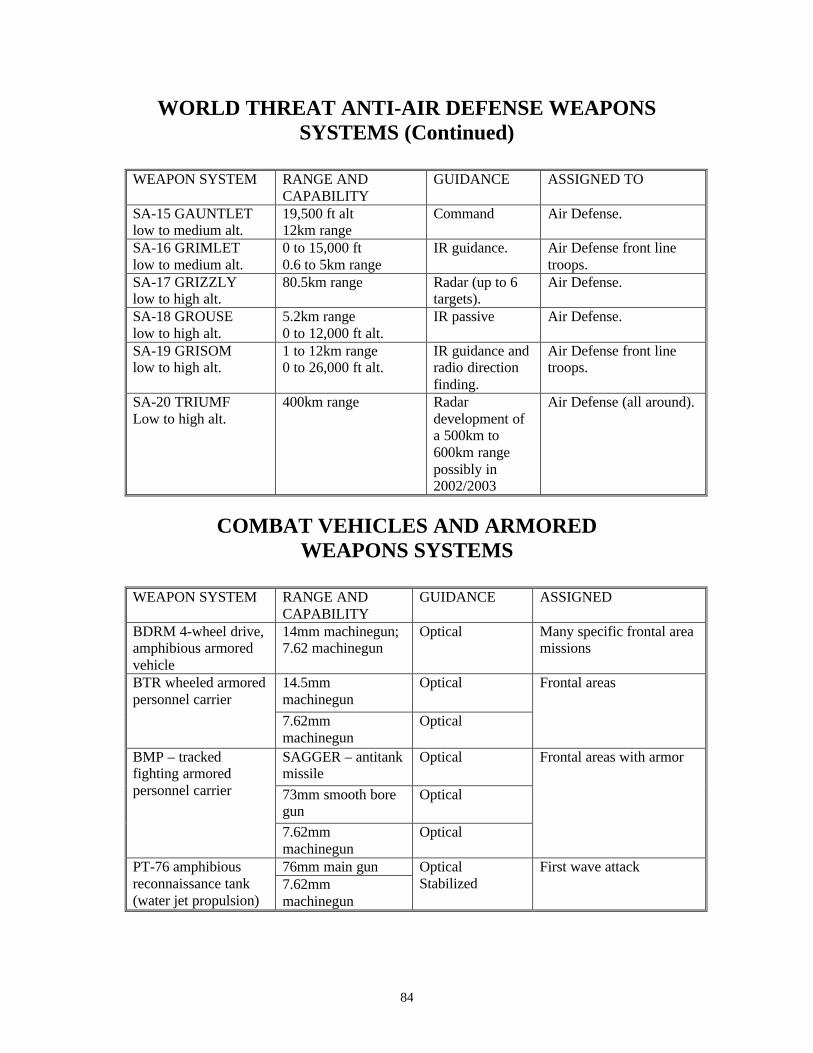
84
WORLD THREAT ANTI-AIR DEFENSE WEAPONS SYSTEMS (Continued)
WEAPON SYSTEM RANGE AND
CAPABILITY GUIDANCE ASSIGNED TO
SA-15 GAUNTLET low to medium alt.
19,500 ft alt 12km range
Command Air Defense.
SA-16 GRIMLET low to medium alt.
0 to 15,000 ft 0.6 to 5km range
IR guidance. Air Defense front line troops.
SA-17 GRIZZLY low to high alt.
80.5km range Radar (up to 6 targets).
Air Defense.
SA-18 GROUSE low to high alt.
5.2km range 0 to 12,000 ft alt.
IR passive Air Defense.
SA-19 GRISOM low to high alt.
1 to 12km range 0 to 26,000 ft alt.
IR guidance and radio direction finding.
Air Defense front line troops.
SA-20 TRIUMF Low to high alt.
400km range Radar development of a 500km to 600km range possibly in 2002/2003
Air Defense (all around).
COMBAT VEHICLES AND ARMORED WEAPONS SYSTEMS
WEAPON SYSTEM RANGE AND
CAPABILITY GUIDANCE ASSIGNED
BDRM 4-wheel drive, amphibious armored vehicle
14mm machinegun; 7.62 machinegun
Optical Many specific frontal area missions
14.5mm machinegun
Optical
BTR wheeled armored personnel carrier
7.62mm machinegun
Optical
Frontal areas
SAGGER – antitank missile
Optical
73mm smooth bore gun
Optical
BMP – tracked fighting armored personnel carrier
7.62mm machinegun
Optical
Frontal areas with armor
76mm main gun PT-76 amphibious reconnaissance tank (water jet propulsion)
7.62mm machinegun
Optical Stabilized
First wave attack
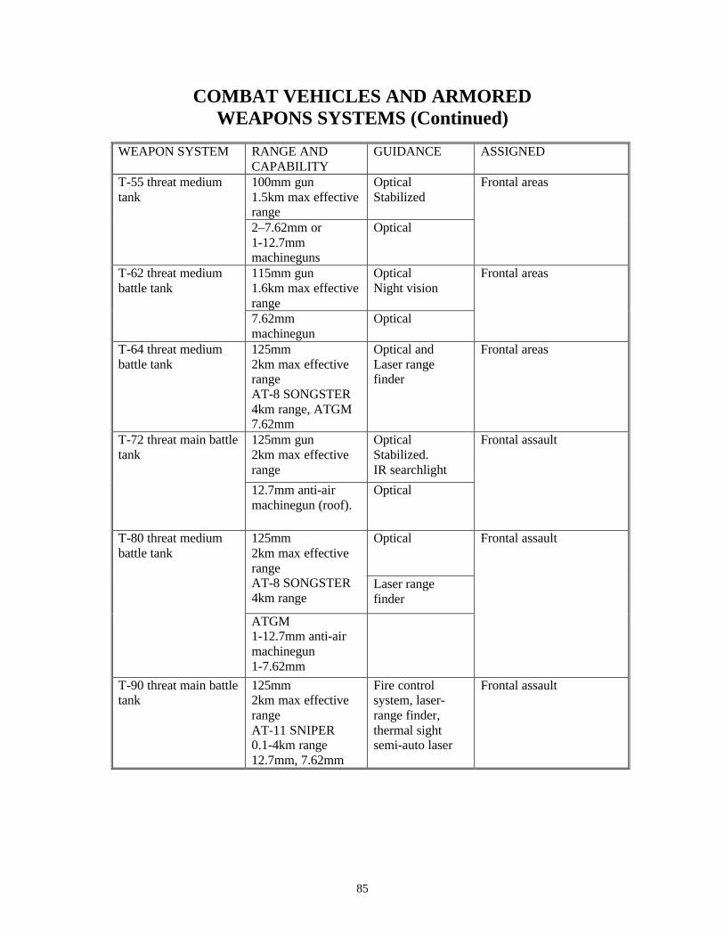
85
COMBAT VEHICLES AND ARMORED WEAPONS SYSTEMS (Continued)
WEAPON SYSTEM RANGE AND
CAPABILITY GUIDANCE ASSIGNED
100mm gun 1.5km max effective range
Optical Stabilized
T-55 threat medium tank
2–7.62mm or 1-12.7mm machineguns
Optical
Frontal areas
115mm gun 1.6km max effective range
Optical Night vision
T-62 threat medium battle tank
7.62mm machinegun
Optical
Frontal areas
T-64 threat medium battle tank
125mm 2km max effective range AT-8 SONGSTER 4km range, ATGM 7.62mm
Optical and Laser range finder
Frontal areas
125mm gun 2km max effective range
Optical Stabilized. IR searchlight
T-72 threat main battle tank
12.7mm anti-air machinegun (roof).
Optical
Frontal assault
Optical
125mm 2km max effective range AT-8 SONGSTER 4km range
Laser range finder
T-80 threat medium battle tank
ATGM 1-12.7mm anti-air machinegun 1-7.62mm
Frontal assault
T-90 threat main battle tank
125mm 2km max effective range AT-11 SNIPER 0.1-4km range 12.7mm, 7.62mm
Fire control system, laser-range finder, thermal sight semi-auto laser
Frontal assault

86
AIR SPEED/VELOCITY CONVERSION TABLE Knots Per-Hour
Miles Per-Hour
Kilometer Per-Hour
Meters Per-
Second
Feet Per-Second
Meters Per-Min
Nautical Miles
Per-Min 1 5
10 15 20 25 30 35 40 45 50 60 70 80 90
100 110 120 130 140 150 160 170 180 190 200 210 220 230 240 250 260 270 280 290 300 310 320 330 340 350
1.15155 5.7
11.5 17.2 23.0 28.8 34.5 40.3 46.0 51.8 57.6 69.1 80.6 92.1
103.6 115 126 138 149 161 172 184 195 207 218 230 241 253 264 276 287 299 310 322 333 345 356 368 380 391 403
1.85325 9.2
18.5 27.7 37.7 46.3 55.5 64.8 74.1 83.3 92.6
111.1 129.7 148.2 166.7
185 203 222 240 259 277 296 315 333 352 370 389 407 426 444 463 481 500 518 537 555 574 592 611 630 648
.51479 2.5 5.1 7.7
10.2 12.8 15.4 18.0 20.9 23.1 25.7 30.8 36.0 41.1 46.3
51 56 61 66 72 77 82 87 92 97
102 107 112 118 123 128 133 139 144 149 154 159 164 169 175 180
1.68894 8.4
16.8 25.3 33.7 42.2 50.6 59.1 67.5 76.0 84.4
101.3 118.2 125.1
152 168 185 202 219 236 253 270 287 304 320 337 354 371 388 405 422 439 456 472 489 506 523 540 557 574 591
30.8874 154.5 308.8 463.3 617.7 772.1 926.6 1081 1235 1389 1544 1853 2162 2470 2779 3087 3397 3706 4015 4324 4633 4941 5250 5559 5868 6177 6486 6795 7104 7412 7721 8030 8339 8648 8957 9266 9575 9883
10,192 10,501 10,810
.0166666
.999999
1.6 1.8 1.9 2.1 2.3 2.4 2.6 2.8 2.9 3.1 3.3 3.4 3.6 3.8 3.9 4.1 4.3 4.4 4.6 4.8 4.9 5.1 5.3 5.4 5.6 5.8
360 370 380 390 400 410 420 430 440 450 460 470 480 490 500 510 520 530 540 550
414 426 437 449 460 472 483 495 506 518 529 541 552 564 575 587 598 610 621 633
667 685 704 722 741 759 778 796 815 833 852 870 889 907 926 945 963 982
1000 1019
185 190 195 200 205 211 216 221 226 231 236 241 247 252 257 262 267 272 278 283
608 624 641 658 675 692 709 726 743 760 776 793 810 827 844 861 878 895 912 928
11,119 11,428 11,737 12,046 12,354 12,663 12,972 13,281 13,590 13,899 14,208 14,517 14,825 15,134 15,443 15,752 16,061 16,370 16,679 16,988
5.9 6.1 6.3 6.4 6.6 6.8 6.9 7.1 7.3 7.4 7.6 7.8 7.9 8.1 8.3 8.4 8.6 8.8 8.9 9.1
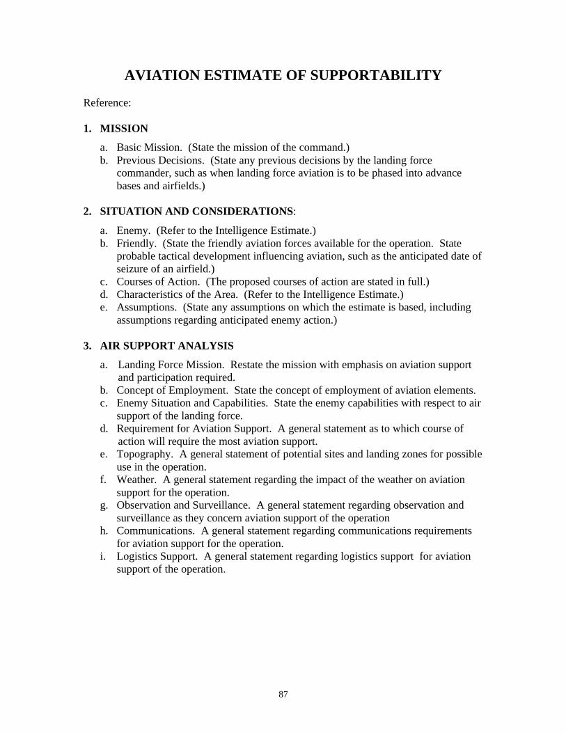
87
AVIATION ESTIMATE OF SUPPORTABILITY Reference: 1. MISSION
a. Basic Mission. (State the mission of the command.) b. Previous Decisions. (State any previous decisions by the landing force
commander, such as when landing force aviation is to be phased into advance bases and airfields.)
2. SITUATION AND CONSIDERATIONS:
a. Enemy. (Refer to the Intelligence Estimate.) b. Friendly. (State the friendly aviation forces available for the operation. State
probable tactical development influencing aviation, such as the anticipated date of seizure of an airfield.)
c. Courses of Action. (The proposed courses of action are stated in full.) d. Characteristics of the Area. (Refer to the Intelligence Estimate.) e. Assumptions. (State any assumptions on which the estimate is based, including
assumptions regarding anticipated enemy action.) 3. AIR SUPPORT ANALYSIS
a. Landing Force Mission. Restate the mission with emphasis on aviation support and participation required.
b. Concept of Employment. State the concept of employment of aviation elements. c. Enemy Situation and Capabilities. State the enemy capabilities with respect to air
support of the landing force. d. Requirement for Aviation Support. A general statement as to which course of
action will require the most aviation support. e. Topography. A general statement of potential sites and landing zones for possible
use in the operation. f. Weather. A general statement regarding the impact of the weather on aviation
support for the operation. g. Observation and Surveillance. A general statement regarding observation and
surveillance as they concern aviation support of the operation h. Communications. A general statement regarding communications requirements
for aviation support for the operation. i. Logistics Support. A general statement regarding logistics support for aviation
support of the operation.
88
AVIATION ESTIMATE OF SUPPORTABILITY (Continued)
4. EVALUATION. Each course of action is evaluated in turn. Advantages are enumerated and then disadvantages enumerated.
5. CONCLUSIONS
a. Best Course. This is a statement of which course of action can best be supported from the aviation point of view.
b. Other Courses. Other courses of action are listed in their order of supportability, and a statement is made of their salient disadvantages.
c. Significant problems. This is a statement of significant problems to be solved and limitations to be taken into account. Measures required to solve the problem should be included.
89
APPENDIX A, JOINT AIR OPERATIONS PLAN FORMAT Referenced from the Joint Publication 3-56.1 Command and Control for Joint Air Operations
(14 Nov 1994) The joint air operations plan format uses the same format as the JFC campaign plan but from an airpower point of view. Each air operations plan will differ with the AOR/JOA, situation, and capabilities of the joint force. A sample format follows:
Copy No Issuing Headquarters Place of Issue
Date/Time Group of Signature JOINT AIR OPERATIONS PLAN: (Number or Code Name) References: Maps, charts, and other relevant documents. COMMAND RELATIONSHIPS. Briefly describe the command organization (composition and relationships) for the JFC's campaign and the air operations envisioned. Detailed information may be included in the command relationships annex. Cover component commanders, AADC, and ACA identities, and others as required.
1. Situation. Briefly describe the situation that the plan addresses (see JFC's estimate). The related CONPLAN or OPLAN should be identified as appropriate.
a. Guidance. Provide a summary of directives, letters of instructions, memorandums, treaties, and strategic plans, including any campaign/operation plans received from higher authority, that apply to the plan.
(1) Relate the strategic direction to the JFC's requirements. (2) List the strategic objectives and tasks assigned to the command. (3) Constraints--list actions that are prohibited or required by higher authority (ROE, and others as appropriate).
b. Adversary Forces. Provide a summary of pertinent intelligence data including information on the following:
(1) Composition, location, disposition, movements, and strengths of major adversary forces that can influence action in the AOR/JOA. (2) Strategic concept (if known), should include adversary's perception of friendly vulnerabilities and adversary's intentions regarding those vulnerabilities. (3) Major objectives (strategic and operational). (4) Adversary commander's idiosyncrasies and doctrinal patterns. (5) Operational and sustainment capabilities. (6) Vulnerabilities. (7) Centers of gravity and decisive points.
NOTE: Assumed information should be identified as such. Reference may be made to the intelligence annex for more detailed information.
90
APPENDIX A, JOINT AIR OPERATIONS PLAN FORMAT (Continued)
c. Friendly Forces. State here information on friendly forces not assigned that may
directly affect the command. (1) Intent of higher, adjacent, and supporting US commands (e.g., USTRANSCOM, USSTRATCOM, USSOCOM, USSPACECOM). (2) Intent of higher, adjacent, and supporting allied or other coalition forces (e.g., NATO, Spain, Italy, Egypt).
d. Assumptions. State here assumptions applicable to the plan as a whole. Include both specified and implied assumptions.
2. Mission. State the joint air task(s) and the purpose(s) and relationship(s) to achieving the JFC's objective(s). 3. Air Operations.
a. Strategic or Operational Concept. (Based on the relevant major elements of JFC strategy.) State the broad concept for the deployment, employment, and sustainment of major air capable joint forces including the concepts of deception and psychological operations during the operation or campaign as a whole. (This section is a summary of details found in annexes.)
(1) Joint force air organization. (2) Joint force air objectives. (3) Bed down overview. (4) Operational missions. (5) Phases of joint air operations in relation to JFC operation or campaign plan. (6) Timing and duration of phases.
b. Phase I. Provide a phase directive for each phase. (1) Operational Concept. Include operational objectives, plan of attack, and timing. (2) General missions and guidance to subordinates and components' supporting and supported requirements. Ensure that missions are complementary. (3) Capabilities/forces required by role or capability. Should consider land, sea, air, space, special operations, and multinational. (4) Tasks of subordinate commands and components. (5) Reserve Forces. Location and composition. State "be prepared" missions. Include guidance on surge sorties if used as reserve capability. (6) Mobility. Consider transportation, ports, lines of communication, transit and over flight rights, reinforcement, reception and onward movement, and host-nation support arrangements. (7) Deception. (8) Psychological Operations. Ensure joint air operations support established psychological operations.
91
APPENDIX A, JOINT AIR OPERATIONS PLAN FORMAT (Continued)
c. Phases II-XX (last). Cite information as stated in subparagraph 3b above for each
subsequent phase. Provide a separate phase for each step in the operation at the end of which a major reorganization of forces may be required and another significant action initiated.
d. Coordinating Instructions. If desired, instructions applicable to two or more phases or multiple elements of the command may be placed here.
4. Logistics. A brief, broad statement of the sustainment concept for the joint air operations with information and instructions applicable to the joint air operations by phase. Logistic phases must be consistent with operational phases. This information may be listed separately and referenced here. This paragraph should address:
a. Assumptions (including coalition requirements). b. Supply aspects. c. Maintenance and modifications. d. Medical service. e. Transportation. f. Base development. g. Personnel. h. Foreign military assistance i. Administrative management. j. Line(s) of communication. k. Reconstitution of forces. l. Joint and multinational responsibilities. m. Sustainment priorities and resources. n. Inter-Service responsibilities. o. Host-nation considerations.
5. Command, Control, and Communications. a. Command.
(1) Command Relationships. State generally the command relationships for the entire joint air operations or portions thereof. Indicate any transfer of forces contemplated during the joint air operations, indicating the time of the expected transfer. These changes should be consistent with the operational phasing in paragraph 3. Give location of commander, JAOC, and command posts. (2) Delegation of Authority.
b. Communications. (1) Communications. Plans of communications. (May refer to a standard plan or be contained in an annex.) Include time zone to be used; rendezvous, recognition, and identification instructions; code; liaison instructions; and axis of signal communications as appropriate.

92
(2) Electronics. Plans of electronic systems. (May refer to standard plan or may be contained in an annex.) Include electronic policy and such other information as may be appropriate. (3) Combat Camera. Plans for combat camera. (May refer to a standard plan or may be contained in a combat camera annex.) Include digital still photo and motion video imagery transmission to the Pentagon's Joint Combat Camera Center. (4) Armament Delivery Recording (ADR) (bomb and gun camera imagery). Plan for ADR. (May refer to a standard plan or may be contained in a combat camera annex.) Include imagery transmission to the Pentagon's Combat Camera Center.
(Signed) (Commander) ANNEXES: As required DISTRIBUTION: SECURITY CLASSIFICATION
Top Related