


Languages
Pages
Legal

Force Five Infinity Air Winches

11
2
ingersollrandproducts.com/lifting
Contents
WARNING: Unless otherwise noted this equipment is not designed for transporting people or lifting loads over people. It is the user’s responsi-bility to determine the suitability of this product for any particular use and to check compliance with applicable regulations. Before installation, see maintenance and operations manual for additional warnings and precautions.
NOTE: Hydraulic models are available, please contact Client Services.
Force Five Infinity Utility Air Winches ..............................3 4,400 lbs (2000 kg) to 22,000 lbs (10000 kg)Designed for offshore and harsh industrial environments the robust Infinity design features rugged radial piston air motors, planetary gearboxes, 5:1 design factors, and a wide variety of standard features and options.
Force Five Infinity Guideline & Podline Air Winches ......15 3,400 lbs (1545 kg) to 10,200 lbs (4636 kg)Designed for offshore oil drilling into deep waters, lowering and recovering sub-sea equipment.
Force Five Infinity Man Rider™ Air Winches..................17 330 lbs (150 kg) to 6,870 lbs (3123 kg)3rd Party Type Approved Infinity Man Riders™ are available in both dedicated and dual purpose configurations and have set the standard for safety, reliability, and solutions worldwide.
Infinity Options & Accessories .........................................27Featuring N4 & N5 - ABS & DNV Regulatory Requirements; -CE components; a visual sample of current Options; Electric over Air remote pendant control system; Accu-Spool™ Level Wind features and details; and Air Line Accessories with Filter, Lubricator, Regulator, Strainer, Muffler & Liquidator.
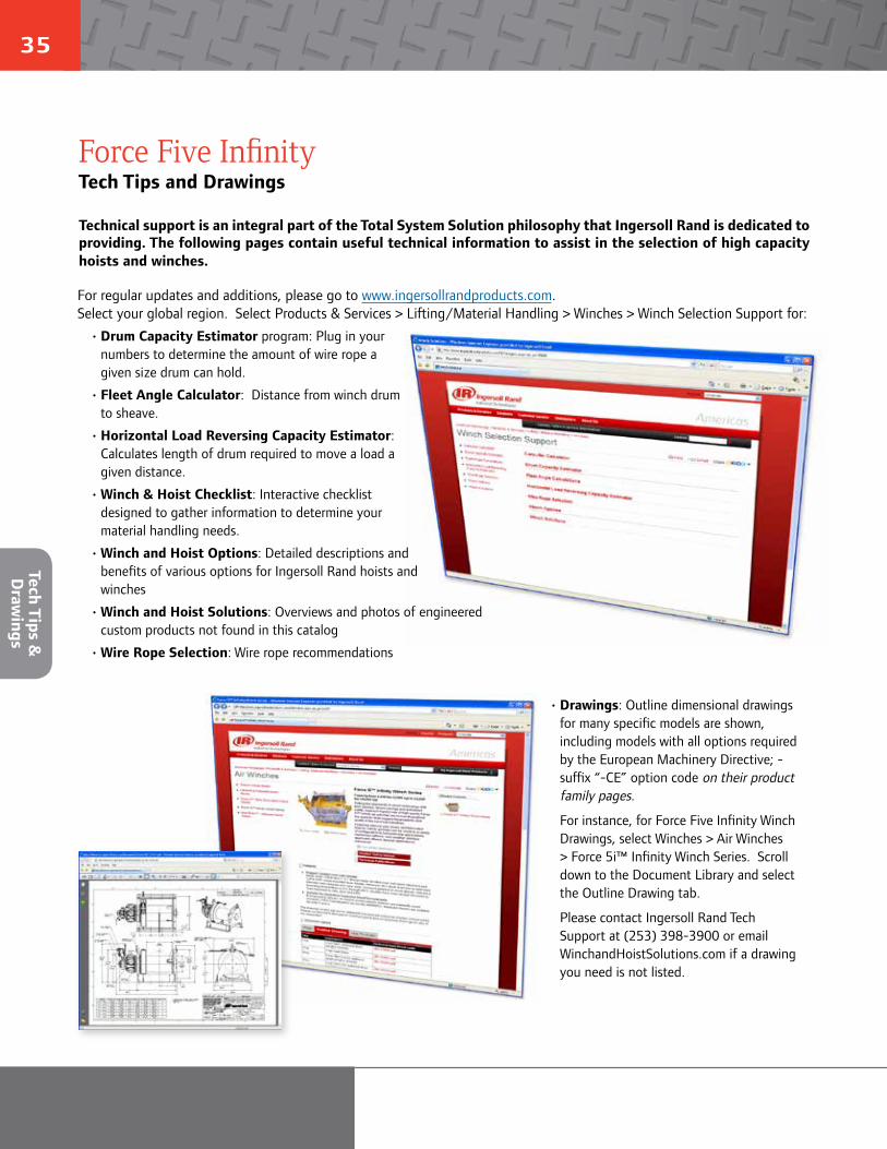
Tech Tips ...........................................................................35A variety of Tech Tips, including Wire Rope Capacity Estimator, Fleet Angle Calculator, Wire Rope Selection tools and Outline Dimension Drawings available from our website.
Winch Checklist ...............................................................37A comprehensive checklist to assist us in providing the product or service to meet your applications specific requirements.
3
Utility
Air W
inches
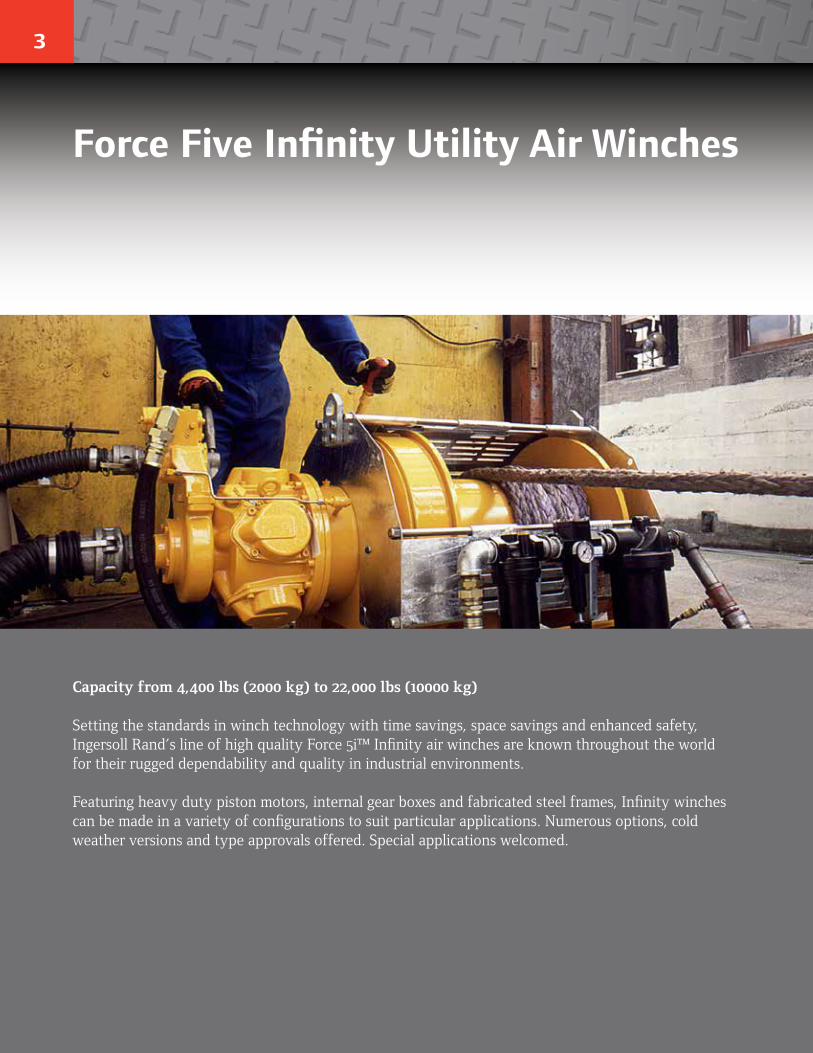
Capacity from 4,400 lbs (2000 kg) to 22,000 lbs (10000 kg)
Setting the standards in winch technology with time savings, space savings and enhanced safety, Ingersoll Rand’s line of high quality Force 5i™ Infinity air winches are known throughout the world for their rugged dependability and quality in industrial environments.
Featuring heavy duty piston motors, internal gear boxes and fabricated steel frames, Infinity winches can be made in a variety of configurations to suit particular applications. Numerous options, cold weather versions and type approvals offered. Special applications welcomed.
Force Five Infinity Utility Air Winches
4
ingersollrandproducts.com/lifting
Rugged Compact and Safe Design• Meets ANSI / ASME B30.7• Minimum 5:1 design factor at rated load• Top layer rated line pull. A Force 5i winch always pulls or lifts its rated capacity at any layer.• “Lift to shift” winch mounted lever throttle • Minimum 18:1 drum diameter to wire rope diameter ratio reduces wire rope wear• Compact gearbox-in-drum design• Standard design temperature range is 0°C through 60°C • Models have been design reviewed or Type Approved by ABS and DNV• Lifting lugs designed for lifting weight of winch plus full drum of wire rope• Group of mechanism as per FEM: 5m
Suitable for Hazardous Explosion Proof Environments• Flameproof by design. Air motors (unlike electric motors) are inherently spark resistant• ATEX classification (as per directive EC 94/9/EEC). CE compliant models marked EX II 2 GD c 200°C X.• Standard models are suitable for ATEX zone 1 and 2.
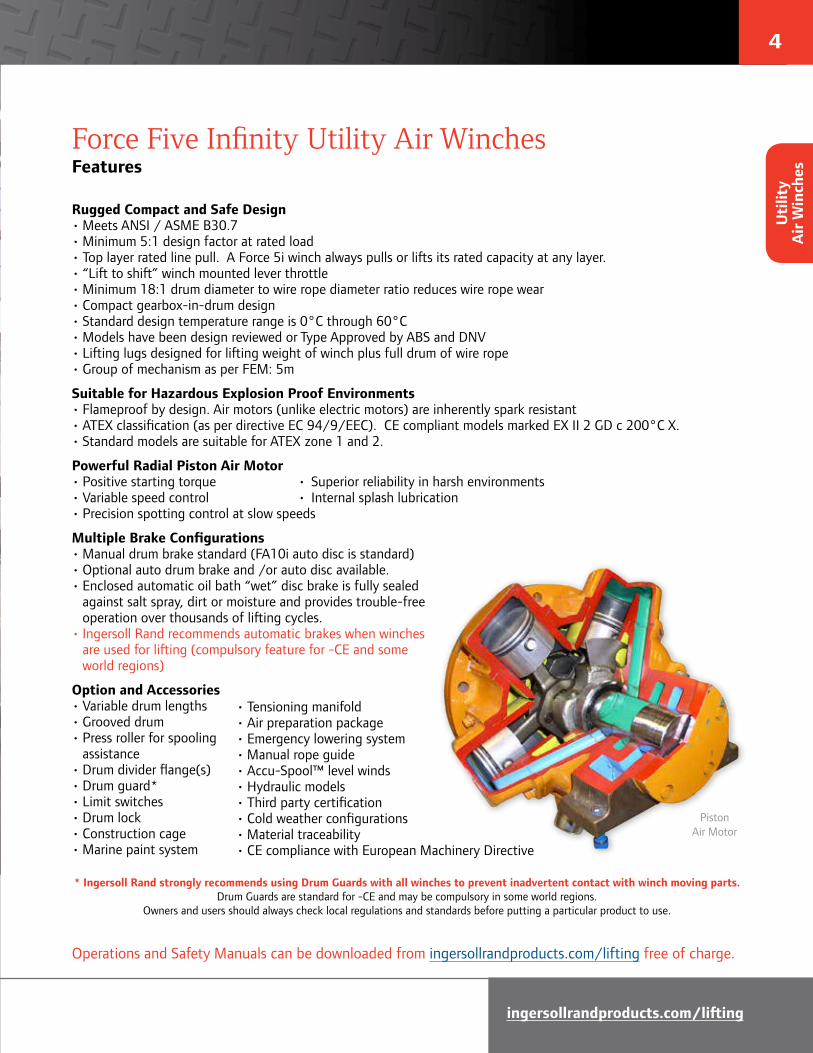
Powerful Radial Piston Air Motor • Positive starting torque • Superior reliability in harsh environments • Variable speed control • Internal splash lubrication• Precision spotting control at slow speeds
Multiple Brake Configurations• Manual drum brake standard (FA10i auto disc is standard)• Optional auto drum brake and /or auto disc available.• Enclosed automatic oil bath “wet” disc brake is fully sealed against salt spray, dirt or moisture and provides trouble-free operation over thousands of lifting cycles. • Ingersoll Rand recommends automatic brakes when winches are used for lifting (compulsory feature for -CE and some world regions)
Option and Accessories• Variable drum lengths• Grooved drum• Press roller for spooling assistance• Drum divider flange(s)• Drum guard*• Limit switches• Drum lock• Construction cage• Marine paint system
Force Five Infinity Utility Air WinchesFeatures
PistonAir Motor
Operations and Safety Manuals can be downloaded from ingersollrandproducts.com/lifting free of charge.
• Tensioning manifold• Air preparation package• Emergency lowering system• Manual rope guide• Accu-Spool™ level winds• Hydraulic models• Third party certification• Cold weather configurations• Material traceability• CE compliance with European Machinery Directive
* Ingersoll Rand strongly recommends using Drum Guards with all winches to prevent inadvertent contact with winch moving parts. Drum Guards are standard for -CE and may be compulsory in some world regions.
Owners and users should always check local regulations and standards before putting a particular product to use.
Uti
lity
Air
Win
ches
5
Force Five Infinity Utility Air WinchesSpecifications & Performance
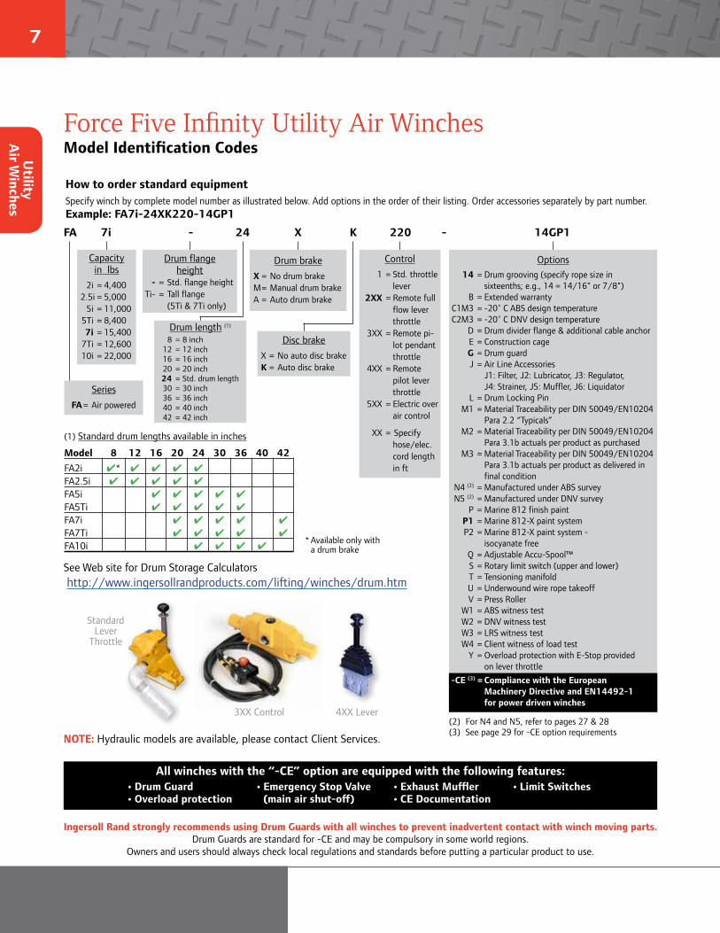
Tip: Infinity winches are rated at Top Layer.
The Infinity winch will always lift its rated load at any layer of wire rope.
➲
How Ingersoll Rand Infinity winches are rated
NOTE: Hydraulic models are available, please contact Client Services.
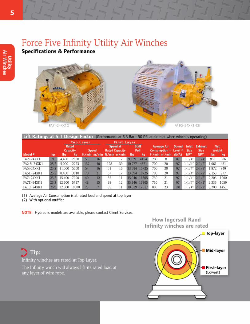
FA10i-24XK1-CEFA7i-24XK1G
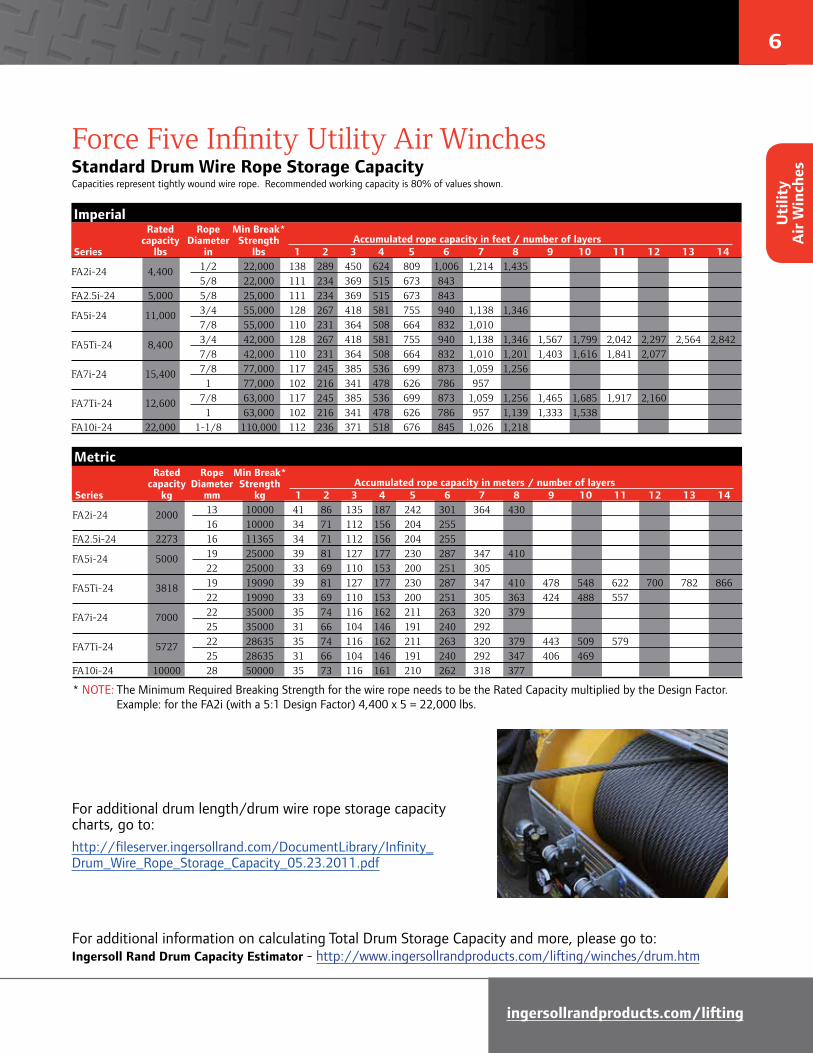
Lift Ratings at 5:1 Design Factor (Performance at 6.3 Bar - 90 PSI at air inlet when winch is operating) Top Layer First Layer Rated Speed at Stall Average Air Sound Inlet Exhaust Net Capacity Speed Rated Capacity Pull Consumption (1) Level (2) Size Size WeightModel # hp lbs kg ft/min m/min ft/min m/min lbs kg f3/min m3/min db(A) NPT NPT lbs kgFA2i-24XK1 9 4,400 2000 51 16 55 17 9,139 4154 280 8 87 1-1/4” 1-1/4” 850 386FA2.5i-24XK1 25.2 5,000 2273 132 40 128 39 10,277 4671 700 20 97 1-1/4” 2-1/2” 1,061 481FA5i-24XK1 25.2 11,000 5000 54 16 51 16 23,594 10725 700 20 97 1-1/4” 2-1/2” 1,872 849FA5Ti-24XK1 25.2 8,400 3818 70 21 57 17 23,594 10725 700 20 97 1-1/4” 2-1/2” 2,153 977FA7i-24XK1 25.2 15,400 7000 40 12 35 11 35,946 16305 750 21 97 1-1/4” 2-1/2” 2,205 1000FA7Ti-24XK1 25.2 12,600 5727 48 15 38 12 35,946 16305 750 21 97 1-1/4” 2-1/2” 2,335 1059FA10i-24XK1 26.9 22,000 10000 23 7 35 11 38,619 17517 800 23 101 1-1/4” 2-1/2” 3,200 1451
(1) Average Air Consumption is at rated load and speed at top layer(2) With optional muffler
Top-layer
Mid-layer
First-layer (Lowest)
Utility
Air W
inches
6
ingersollrandproducts.com/lifting
Force Five Infinity Utility Air WinchesStandard Drum Wire Rope Storage Capacity Capacities represent tightly wound wire rope. Recommended working capacity is 80% of values shown.
For additional information on calculating Total Drum Storage Capacity and more, please go to: Ingersoll Rand Drum Capacity Estimator - http://www.ingersollrandproducts.com/lifting/winches/drum.htm
* NOTE: The Minimum Required Breaking Strength for the wire rope needs to be the Rated Capacity multiplied by the Design Factor. Example: for the FA2i (with a 5:1 Design Factor) 4,400 x 5 = 22,000 lbs.
Imperial Rated Rope Min Break* capacity Diameter Strength Accumulated rope capacity in feet / number of layers Series lbs in lbs 1 2 3 4 5 6 7 8 9 10 11 12 13 14
FA2i-24 4,400 1/2 22,000 138 289 450 624 809 1,006 1,214 1,435 5/8 22,000 111 234 369 515 673 843 FA2.5i-24 5,000 5/8 25,000 111 234 369 515 673 843
FA5i-24 11,000 3/4 55,000 128 267 418 581 755 940 1,138 1,346 7/8 55,000 110 231 364 508 664 832 1,010
FA5Ti-24 8,400 3/4 42,000 128 267 418 581 755 940 1,138 1,346 1,567 1,799 2,042 2,297 2,564 2,842 7/8 42,000 110 231 364 508 664 832 1,010 1,201 1,403 1,616 1,841 2,077
FA7i-24 15,400 7/8 77,000 117 245 385 536 699 873 1,059 1,256 1 77,000 102 216 341 478 626 786 957
FA7Ti-24 12,600 7/8 63,000 117 245 385 536 699 873 1,059 1,256 1,465 1,685 1,917 2,160 1 63,000 102 216 341 478 626 786 957 1,139 1,333 1,538FA10i-24 22,000 1-1/8 110,000 112 236 371 518 676 845 1,026 1,218
For additional drum length/drum wire rope storage capacity charts, go to:http://fileserver.ingersollrand.com/DocumentLibrary/Infinity_Drum_Wire_Rope_Storage_Capacity_05.23.2011.pdf
Metric Rated Rope Min Break* capacity Diameter Strength Accumulated rope capacity in meters / number of layers Series kg mm kg 1 2 3 4 5 6 7 8 9 10 11 12 13 14
FA2i-24 2000 13 10000 41 86 135 187 242 301 364 430 16 10000 34 71 112 156 204 255 FA2.5i-24 2273 16 11365 34 71 112 156 204 255
FA5i-24 5000 19 25000 39 81 127 177 230 287 347 410 22 25000 33 69 110 153 200 251 305
FA5Ti-24 3818 19 19090 39 81 127 177 230 287 347 410 478 548 622 700 782 866 22 19090 33 69 110 153 200 251 305 363 424 488 557
FA7i-24 7000 22 35000 35 74 116 162 211 263 320 379 25 35000 31 66 104 146 191 240 292
FA7Ti-24 5727 22 28635 35 74 116 162 211 263 320 379 443 509 579 25 28635 31 66 104 146 191 240 292 347 406 469 FA10i-24 10000 28 50000 35 73 116 161 210 262 318 377
Uti
lity
Air
Win
ches
7
Force Five Infinity Utility Air WinchesModel Identification Codes
How to order standard equipmentSpecify winch by complete model number as illustrated below. Add options in the order of their listing. Order accessories separately by part number.Example: FA7i-24XK220-14GP1
Drum brakeX = No drum brakeM = Manual drum brakeA = Auto drum brake
Disc brakeX = No auto disc brakeK = Auto disc brake
Drum flangeheight
- = Std. flange height Ti- = Tall flange (5Ti & 7Ti only)
Capacityin lbs
2i = 4,400 2.5i = 5,000 5i = 11,000 5Ti = 8,400 7i = 15,400 7Ti = 12,600 10i = 22,000
Drum length (1)
8 = 8 inch 12 = 12 inch 16 = 16 inch 20 = 20 inch 24 = Std. drum length 30 = 30 inch 36 = 36 inch 40 = 40 inch 42 = 42 inch
Options 14 = Drum grooving (specify rope size in sixteenths; e.g., 14 = 14/16" or 7/8") B = Extended warranty C1M3 = -20˚ C ABS design temperature C2M3 = -20˚ C DNV design temperature D = Drum divider flange & additional cable anchor E = Construction cage G = Drum guard J = Air Line Accessories J1: Filter, J2: Lubricator, J3: Regulator, J4: Strainer, J5: Muffler, J6: Liquidator L = Drum Locking Pin M1 = Material Traceability per DIN 50049/EN10204 Para 2.2 “Typicals” M2 = Material Traceability per DIN 50049/EN10204 Para 3.1b actuals per product as purchased M3 = Material Traceability per DIN 50049/EN10204 Para 3.1b actuals per product as delivered in final condition N4 (2) = Manufactured under ABS survey N5 (2) = Manufactured under DNV survey P = Marine 812 finish paint P1 = Marine 812-X paint system P2 = Marine 812-X paint system - isocyanate free Q = Adjustable Accu-Spool™ S = Rotary limit switch (upper and lower) T = Tensioning manifold U = Underwound wire rope takeoff V = Press Roller W1 = ABS witness test W2 = DNV witness test W3 = LRS witness test W4 = Client witness of load test Y = Overload protection with E-Stop provided on lever throttle -CE (3) = Compliance with the European Machinery Directive and EN14492-1 for power driven winches
SeriesFA = Air powered
FA 7i - 24 X K 220 - 14GP1
All winches with the “-CE” option are equipped with the following features:
NOTE: Hydraulic models are available, please contact Client Services.
See Web site for Drum Storage Calculators http://www.ingersollrandproducts.com/lifting/winches/drum.htm
(1) Standard drum lengths available in inches
Model 8 12 16 20 24 30 36 40 42FA2i 4* 4 4 4 4
FA2.5i 4 4 4 4 4
FA5i 4 4 4 4 4 FA5Ti 4 4 4 4 4
FA7i 4 4 4 4 4 FA7Ti 4 4 4 4 4
FA10i 4 4 4 4
Control 1 = Std. throttle
lever 2XX = Remote full
flow lever throttle
3XX = Remote pi-lot pendant throttle
4XX = Remote pilot lever throttle
5XX = Electric over air control
XX = Specify hose/elec. cord length in ft
(2) For N4 and N5, refer to pages 27 & 28(3) See page 29 for -CE option requirements
Standard Lever
Throttle
4XX Lever3XX Control
* Available only with a drum brake
• Drum Guard• Overload protection
• Emergency Stop Valve (main air shut-off)
• Exhaust Muffler• CE Documentation
• Limit Switches
Ingersoll Rand strongly recommends using Drum Guards with all winches to prevent inadvertent contact with winch moving parts. Drum Guards are standard for -CE and may be compulsory in some world regions.
Owners and users should always check local regulations and standards before putting a particular product to use.
Utility
Air W
inches
8
ingersollrandproducts.com/lifting
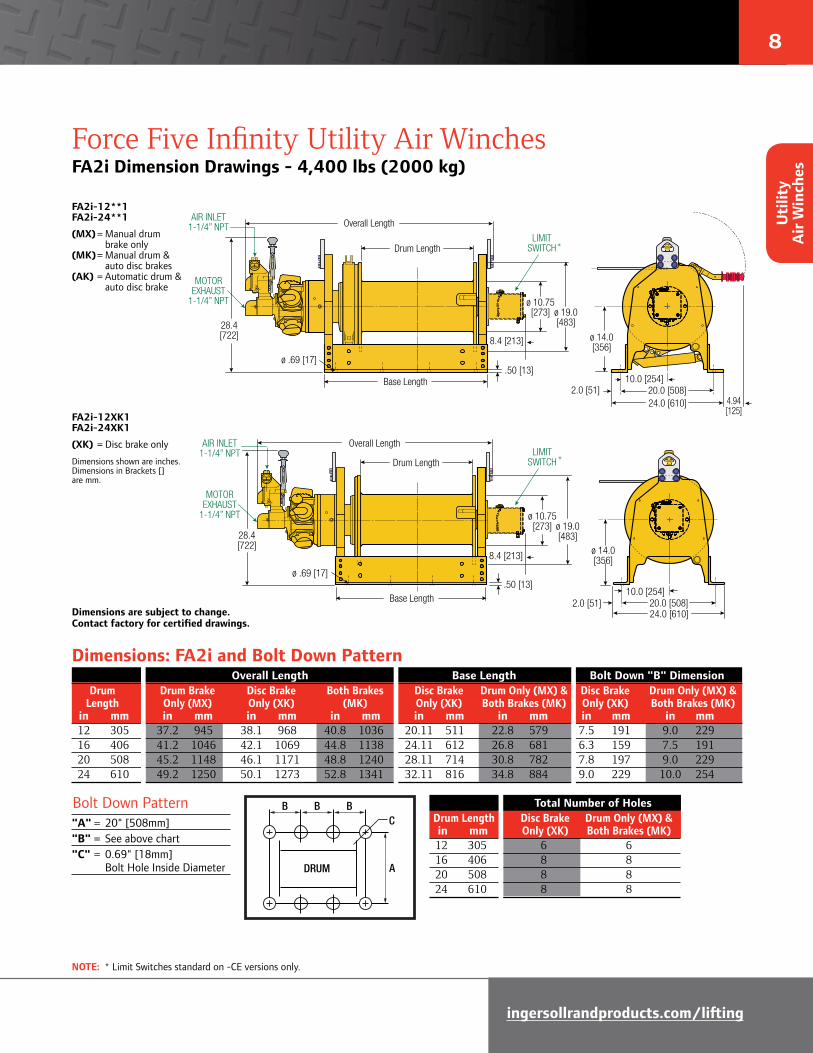
Force Five Infinity Utility Air WinchesFA2i Dimension Drawings - 4,400 lbs (2000 kg)
FA2i-12**1 FA2i-24**1
(MX) = Manual drum brake only (MK) = Manual drum & auto disc brakes (AK) = Automatic drum & auto disc brake
FA2i-12XK1 FA2i-24XK1
(XK) = Disc brake only
Dimensions shown are inches.Dimensions in Brackets [] are mm.
Dimensions are subject to change. Contact factory for certified drawings.
Dimensions: FA2i and Bolt Down Pattern
DRUM
BB B
A
C
Bolt Down Pattern"A" = 20" [508mm]"B" = See above chart"C" = 0.69" [18mm] Bolt Hole Inside Diameter
Overall Length Base Length Bolt Down "B" Dimension Drum Drum Brake Disc Brake Both Brakes Disc Brake Drum Only (MX) & Disc Brake Drum Only (MX) & Length Only (MX) Only (XK) (MK) Only (XK) Both Brakes (MK) Only (XK) Both Brakes (MK) in mm in mm in mm in mm in mm in mm in mm in mm 12 305 37.2 945 38.1 968 40.8 1036 20.11 511 22.8 579 7.5 191 9.0 229 16 406 41.2 1046 42.1 1069 44.8 1138 24.11 612 26.8 681 6.3 159 7.5 191 20 508 45.2 1148 46.1 1171 48.8 1240 28.11 714 30.8 782 7.8 197 9.0 229 24 610 49.2 1250 50.1 1273 52.8 1341 32.11 816 34.8 884 9.0 229 10.0 254
Total Number of Holes Drum Length Disc Brake Drum Only (MX) & in mm Only (XK) Both Brakes (MK) 12 305 6 6 16 406 8 8 20 508 8 8 24 610 8 8
NOTE: * Limit Switches standard on -CE versions only.
FA2i-XK1 with Disc Brake only.
DIMENSIONS SHOWN ARE INCHESDIMENSIONS IN BRACKETS [ ] ARE mm.
AIR INLET 1-1/4” NPT
MOTOR EXHAUST
1-1/4” NPT
Drum Length
Base Length.50 [13]
ø .69 [17]
ø 14.0[356]
10.0 [254]20.0 [508]2.0 [51]24.0 [610]
ø 10.75[273] ø 19.0
[483]28.4[722]
Overall Length
8.4 [213]
LIMITSWITCH
8.4 [213]
LIMITSWITCH*
Overall Length
Drum Length
Base Length
FA2i-MK1 with Disc Brake andBand Brake or Band Brake only.
DIMENSIONS SHOWN ARE INCHESDIMENSIONS IN BRACKETS [ ] ARE mm.
.50 [13]ø .69 [17]
24” wide
8.4 [213]
AIR INLET 1-1/4” NPT
MOTOR EXHAUST
1-1/4” NPT
LIMITSWITCH
ø 14.0[356]
10.0 [254]2.0 [51]
24.0 [610]
ø 10.75[273] ø 19.0
[483]28.4[722]
4.94[125]
20.0 [508]
*
Uti
lity
Air
Win
ches
9
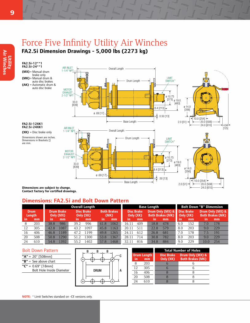
Force Five Infinity Utility Air WinchesFA2.5i Dimension Drawings - 5,000 lbs (2273 kg)
FA2.5i-12**1 FA2.5i-24**1
(MX) = Manual drum brake only (MK) = Manual drum & auto disc brakes (AK) = Automatic drum & auto disc brake
FA2.5i-12XK1 FA2.5i-24XK1
(XK) = Disc brake only
Dimensions shown are inches.Dimensions in Brackets [] are mm.
Dimensions are subject to change. Contact factory for certified drawings.
Dimensions: FA2.5i and Bolt Down Pattern
DRUM
BB B
A
C
Bolt Down Pattern"A" = 20" [508mm]"B" = See above chart"C" = 0.69" [18mm] Bolt Hole Inside Diameter
Overall Length Base Length Bolt Down "B" Dimension Drum Drum Brake Disc Brake Both Brakes Disc Brake Drum Only (MX) & Disc Brake Drum Only (MX) & Length Only (MX) Only (XK) (MK) Only (XK) Both Brakes (MK) Only (XK) Both Brakes (MK) in mm in mm in mm in mm in mm in mm in mm in mm 8 203 38.8 986 39.2 996 41.8 1062 16.11 409 18.8 478 6.0 152 7.0 178 12 305 42.8 1087 43.2 1097 45.8 1163 20.11 511 22.8 579 8.0 203 9.0 229 16 406 46.8 1189 47.2 1199 49.8 1265 24.11 612 26.8 681 7.0 178 7.5 191 20 508 50.8 1290 51.2 1300 53.8 1367 28.11 714 30.8 782 8.0 203 9.0 229 24 610 54.8 1392 55.2 1402 57.8 1468 32.11 816 34.8 884 9.0 229 10.0 254
Total Number of Holes Drum Length Disc Brake Drum Only (MX) & in mm Only (XK) Both Brakes (MK) 8 203 6 6 12 305 6 6 16 406 8 8 20 508 8 8 24 610 8 8
NOTE: * Limit Switches standard on -CE versions only.
FA2.5i-XK1 with Disc Brake only.
DIMENSIONS SHOWN ARE INCHESDIMENSIONS IN BRACKETS [ ] ARE mm.
33.0[839]
ø 10.75[273] ø 19.0
[483]
24.0 [610]
ø 14.0[356]
10.0 [254]20.0 [508]2.0 [51]
.50 [13]ø .69 [17]
Base Length
Drum Length
Overall LengthAIR INLET
1-1/4” NPT
MOTOR EXHAUST
2-1/2” NPT
8.4 [213]
LIMITSWITCH*
33.0[839]
ø 10.75[273] ø 19.0
[483]
Overall Length
24.0 [610]
FA2.5i-MK1 with Disc Brake andBand Brakes or Band Brake only.
DIMENSIONS SHOWN ARE INCHESDIMENSIONS IN BRACKETS [ ] ARE mm.
ø 14.0[356]
4.94[125]
10.0 [254]20.0 [508]2.0 [51]
0.50 [13]ø .69 [17]
Drum Length
Base Length
AIR INLET 1-1/4” NPT
MOTOR EXHAUST
2-1/2” NPT
8.4 [213]
LIMITSWITCH*
Utility
Air W
inches

10
ingersollrandproducts.com/lifting
Force Five Infinity Utility Air WinchesFA5i Dimension Drawings - 11,000 lbs (5000 kg)
FA5i-16**1 FA5i-24**1
(MX) = Manual drum brake only (MK) = Manual drum & auto disc brakes (AK) = Automatic drum & auto disc brake
FA5i-16XK1 FA5i-24XK1
(XK) = Disc brake only
Dimensions shown are inches.Dimensions in Brackets [] are mm.
Dimensions are subject to change. Contact factory for certified drawings.
Dimensions: FA5i and Bolt Down Pattern
DRUM
BB B
A
C
Bolt Down Pattern"A" = 31.25" [794mm]"B" = See above chart"C" = 0.81" [21mm] Bolt Hole Inside Diameter
Overall Length Base Length Bolt Down "B" Dimension Drum Drum Brake Disc Brake Both Brakes Disc Brake Drum Only (MX) & Disc Brake Drum Only (MX) & Length Only (MX) Only (XK) (MK) Only (XK) Both Brakes (MK) Only (XK) Both Brakes (MK) in mm in mm in mm in mm in mm in mm in mm in mm 16 406 48.6 1234 47.4 1204 51.6 1311 23.84 605 28.34 720 6.25 159 9.0 229 20 508 52.6 1336 51.4 1306 55.6 1412 27.84 707 32.34 821 8.5 216 10.0 254 24 610 56.6 1438 55.4 1407 59.6 1514 31.84 809 36.34 923 9.0 229 10.5 267 30 762 62.6 1590 61.4 1560 65.6 1666 37.84 961 42.34 1075 12.0 305 10.0 254 36 914 68.6 1742 67.4 1712 71.6 1819 43.84 1114 48.34 1228 14.0 356 11.0 279
Total Number of Holes Drum Length Disc Brake Drum Only (MX) & in mm Only (XK) Both Brakes (MK) 16 406 6 6 20 508 8 8 24 610 8 8 30 762 8 10 36 914 8 10
NOTE: * Limit Switches standard on -CE versions only.
FA5i-XK1 with Disc Brake only.
DIMENSIONS SHOWN ARE INCHESDIMENSIONS IN BRACKETS [ ] ARE mm.
AIR INLET 1-1/4” NPT
MOTOR EXHAUST
2-1/2” NPT
36.5[928]
ø 15.0[381]
ø 27.0[686]
ø 17.5[445]
15.63 [397]31.25 [794]1.88 [47]35.0 [889]
.75 [19]
ø .81 [21]
Base Length
Drum Length
Overall Length
8.4 [213]
LIMITSWITCH*
FA5i-MK1 with Disc Brake andBand Brakes or Band Brake only.
DIMENSIONS SHOWN ARE INCHESDIMENSIONS IN BRACKETS [ ] ARE mm.
36.5[928]
ø 15.0[381]
ø 27.0[686]
2.59[66]
ø 17.5[445]
15.63 [397]31.25 [794]1.88 [47]35.0 [889]
.75 [19]ø .81 [21]
Overall Length
Base Length
AIR INLET 1-1/4” NPT
MOTOR EXHAUST
2-1/2” NPT
Drum Length
8.4 [213]
LIMITSWITCH*
Uti
lity
Air
Win
ches
11
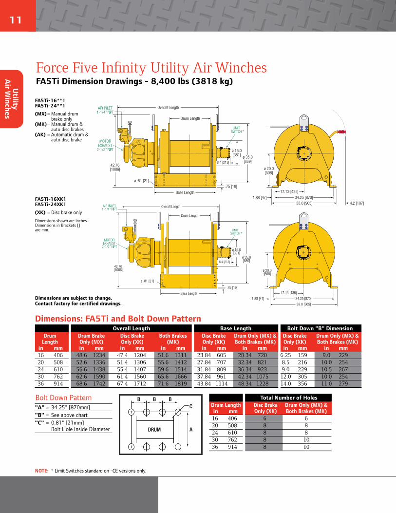
Force Five Infinity Utility Air WinchesFA5Ti Dimension Drawings - 8,400 lbs (3818 kg)
FA5Ti-16**1 FA5Ti-24**1
(MX) = Manual drum brake only (MK) = Manual drum & auto disc brakes (AK) = Automatic drum & auto disc brake
FA5Ti-16XK1 FA5Ti-24XK1
(XK) = Disc brake only
Dimensions shown are inches.Dimensions in Brackets [] are mm.
Dimensions are subject to change. Contact factory for certified drawings.
Dimensions: FA5Ti and Bolt Down Pattern
DRUM
BB B
A
C
Bolt Down Pattern"A" = 34.25" [870mm]"B" = See above chart"C" = 0.81" [21mm] Bolt Hole Inside Diameter
Overall Length Base Length Bolt Down "B" Dimension Drum Drum Brake Disc Brake Both Brakes Disc Brake Drum Only (MX) & Disc Brake Drum Only (MX) & Length Only (MX) Only (XK) (MK) Only (XK) Both Brakes (MK) Only (XK) Both Brakes (MK) in mm in mm in mm in mm in mm in mm in mm in mm 16 406 48.6 1234 47.4 1204 51.6 1311 23.84 605 28.34 720 6.25 159 9.0 229 20 508 52.6 1336 51.4 1306 55.6 1412 27.84 707 32.34 821 8.5 216 10.0 254 24 610 56.6 1438 55.4 1407 59.6 1514 31.84 809 36.34 923 9.0 229 10.5 267 30 762 62.6 1590 61.4 1560 65.6 1666 37.84 961 42.34 1075 12.0 305 10.0 254 36 914 68.6 1742 67.4 1712 71.6 1819 43.84 1114 48.34 1228 14.0 356 11.0 279
Total Number of Holes Drum Length Disc Brake Drum Only (MX) & in mm Only (XK) Both Brakes (MK) 16 406 6 6 20 508 8 8 24 610 8 8 30 762 8 10 36 914 8 10
NOTE: * Limit Switches standard on -CE versions only.
FA5Ti-XK1 with Disc Brake only.
DIMENSIONS SHOWN ARE INCHESDIMENSIONS IN BRACKETS [ ] ARE mm.
AIR INLET 1-1/4” NPT
MOTOR EXHAUST
2-1/2” NPT
42.76[1086]
ø 15.0[381]
ø 35.0[889]
ø 20.0[508]
17.13 [435]
34.25 [870]1.88 [47]
38.0 [965]
.75 [19]
ø .81 [21]
Base Length
Overall Length
Drum Length
8.4 [213]
LIMITSWITCH*
FA5Ti-MK1 with Disc Brake andBand Brakes or Band Brake only.
DIMENSIONS SHOWN ARE INCHESDIMENSIONS IN BRACKETS [ ] ARE mm.
42.76[1086]
ø 15.0[381] ø 35.0
[889]
ø 20.0[508]
17.13 [435]34.25 [870]1.88 [47]38.0 [965] 4.2 [107]
.75 [19]ø .81 [21]
Overall Length
Drum Length
AIR INLET 1-1/4” NPT
MOTOR EXHAUST
2-1/2” NPT
Base Length
8.4 [213]
LIMITSWITCH*
Utility
Air W
inches
12
ingersollrandproducts.com/lifting
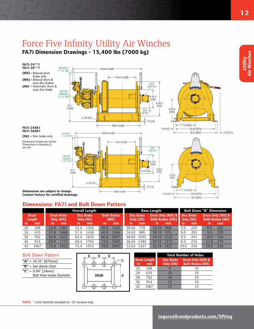
Force Five Infinity Utility Air WinchesFA7i Dimension Drawings - 15,400 lbs (7000 kg)
FA7i-24**1 FA7i-36**1
(MX) = Manual drum brake only (MK) = Manual drum & auto disc brakes (AK) = Automatic drum & auto disc brake
FA7i-24XK1 FA7i-36XK1
(XK) = Disc brake only
Dimensions shown are inches.Dimensions in Brackets [] are mm.
Dimensions are subject to change. Contact factory for certified drawings.
Dimensions: FA7i and Bolt Down Pattern
DRUM
BB B
A
C
Bolt Down Pattern"A" = 34.25" [870mm]"B" = See above chart"C" = 0.94" [24mm] Bolt Hole Inside Diameter
Overall Length Base Length Bolt Down "B" Dimension Drum Drum Brake Disc Brake Both Brakes Disc Brake Drum Only (MX) & Disc Brake Drum Only (MX) & Length Only (MX) Only (XK) (MK) Only (XK) Both Brakes (MK) Only (XK) Both Brakes (MK) in mm in mm in mm in mm in mm in mm in mm in mm 20 508 53.8 1367 53.4 1356 56.8 1443 30.63 778 34.19 868 9.0 229 8.0 203 24 610 57.8 1468 57.4 1458 60.8 1544 34.63 880 38.19 970 8.0 203 9.0 229 30 762 63.8 1621 63.4 1610 66.8 1697 40.63 1032 44.19 1122 9.5 241 10.0 254 36 914 69.8 1773 69.4 1763 72.8 1849 46.63 1184 50.19 1275 8.5 216 11.0 279 42 1067 75.8 1925 75.4 1915 78.8 2002 52.63 1337 56.19 1427 10.0 254 10.0 254
Total Number of Holes Drum Length Disc Brake Drum Only (MX) & in mm Only (XK) Both Brakes (MK) 20 508 8 10 24 610 10 10 30 762 10 10 36 914 12 10 42 1067 12 12
NOTE: * Limit Switches standard on -CE versions only.
FA7i-XK1 with Disc Brake only.
DIMENSIONS SHOWN ARE INCHESDIMENSIONS IN BRACKETS [ ] ARE mm.
AIR INLET 1-1/4” NPT
MOTOR EXHAUST
2-1/2” NPT
.75 [19]
ø .94 [24]
ø 20.0[508]
17.13 [435]
34.26 [870]1.84 [47]
38.0 [965]
ø 30.0[762]
ø 16.0[406]
42.7[1084]
Overall Length
Drum Length
Base Length
8.4 [213]
LIMITSWITCH*
FA7i-MK1 with Disc Brake andBand Brake
DIMENSIONS SHOWN ARE INCHESDIMENSIONS IN BRACKETS [ ] ARE mm.
.75 [19]ø .94 [24]
ø 20.0[508]
17.13 [435]34.26 [870]1.84 [47]38.0 [965] 2.79 [71]
ø 30.0[762]
ø 16.0[406]
42.7[1084]
Overall Length
Drum Length
Base Length
AIR INLET 1-1/4” NPT
MOTOR EXHAUST
2-1/2” NPT
8.4 [213]
LIMITSWITCH*
Uti
lity
Air
Win
ches
13
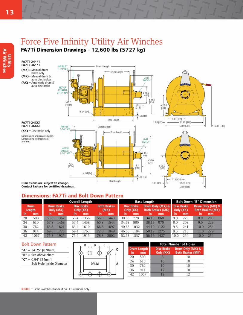
Force Five Infinity Utility Air WinchesFA7Ti Dimension Drawings - 12,600 lbs (5727 kg)
FA7Ti-XK1 with Disc Brake only.
DIMENSIONS SHOWN ARE INCHESDIMENSIONS IN BRACKETS [ ] ARE mm.
AIR INLET 1-1/4” NPT
MOTOR EXHAUST
2-1/2” NPT
.75 [19]
ø .94 [24]
ø 20.0[508]
17.13 [435]34.26 [870]1.84 [47]
38.0 [965]
ø 36.0[914]
ø 16.0[406]
42.7[1084]
Overall Length
Drum Length
Base Length
8.4 [213]
LIMITSWITCH
FA7Ti-24**1 FA7Ti-36**1
(MX) = Manual drum brake only (MK) = Manual drum & auto disc brakes (AK) = Automatic drum & auto disc brake
FA7Ti-24XK1 FA7Ti-36XK1
(XK) = Disc brake only
Dimensions shown are inches.Dimensions in Brackets [] are mm.
Dimensions are subject to change. Contact factory for certified drawings.
Dimensions: FA7Ti and Bolt Down Pattern
DRUM
BB B
A
C
Bolt Down Pattern"A" = 34.25" [870mm]"B" = See above chart"C" = 0.94" [24mm] Bolt Hole Inside Diameter
Overall Length Base Length Bolt Down "B" Dimension Drum Drum Brake Disc Brake Both Brakes Disc Brake Drum Only (MX) & Disc Brake Drum Only (MX) & Length Only (MX) Only (XK) (MK) Only (XK) Both Brakes (MK) Only (XK) Both Brakes (MK) in mm in mm in mm in mm in mm in mm in mm in mm 20 508 53.8 1367 53.4 1356 56.8 1443 30.63 778 34.19 868 9.0 229 8.0 203 24 610 57.8 1468 57.4 1458 60.8 1544 34.63 880 38.19 970 8.0 203 9.0 229 30 762 63.8 1621 63.4 1610 66.8 1697 40.63 1032 44.19 1122 9.5 241 10.0 254 36 914 69.8 1773 69.4 1763 72.8 1849 46.63 1184 50.19 1275 8.5 216 11.0 279 42 1067 75.8 1925 75.4 1915 78.8 2002 52.63 1337 56.19 1427 10.0 254 10.0 254
Total Number of Holes Drum Length Disc Brake Drum Only (MX) & in mm Only (XK) Both Brakes (MK) 20 508 8 10 24 610 10 10 30 762 10 10 36 914 12 10 42 1067 12 12
NOTE: * Limit Switches standard on -CE versions only.
FA7Ti-XK1 with Disc Brake only.
DIMENSIONS SHOWN ARE INCHESDIMENSIONS IN BRACKETS [ ] ARE mm.
AIR INLET 1-1/4” NPT
MOTOR EXHAUST
2-1/2” NPT
.75 [19]
ø .94 [24]
ø 20.0[508]
17.13 [435]34.26 [870]1.84 [47]
38.0 [965]
ø 36.0[914]
ø 16.0[406]
42.7[1084]
Overall Length
Drum Length
Base Length
8.4 [213]
LIMITSWITCH*
SHUT OFFVALVE
'G'
CABLEANCHORPOCKET
PLACES
1.87[ 47]
34.26[ 870]
'C' 'D' 'D' 'D'O .94[ 24] 'D'
FA7Ti-MK1 with Disc Brake andBand Brake
DIMENSIONS SHOWN ARE INCHESDIMENSIONS IN BRACKETS [ ] ARE mm.
AIR INLET 1-1/4” NPT
MOTOR EXHAUST
2-1/2” NPT
.75 [19]
ø .94 [24]
ø 20.0[508]
17.13 [435]34.26 [870]1.84 [47]38.0 [965]
ø 36.0[914]
ø 16.0[406]
42.7[1084]
5.38 [137]
Overall Length
Drum Length
Base Length
8.4 [213]
LIMITSWITCH*
Utility
Air W
inches
14
ingersollrandproducts.com/lifting
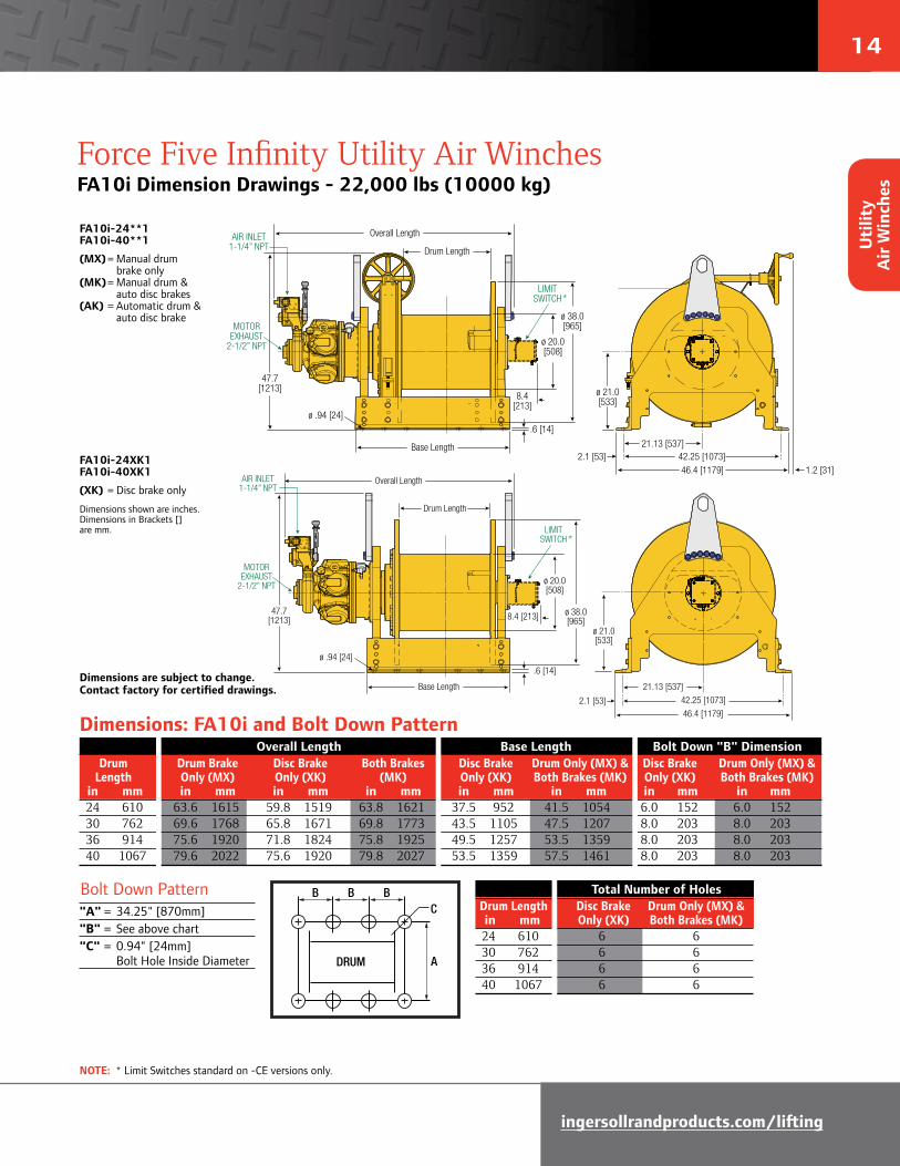
Force Five Infinity Utility Air WinchesFA10i Dimension Drawings - 22,000 lbs (10000 kg)
FA10i-XK1 with Disc Brake,No Band BrakeDIMENSIONS SHOWN ARE INCHESDIMENSIONS IN BRACKETS [ ] ARE mm.
AIR INLET 1-1/4” NPT
MOTOR EXHAUST
2-1/2” NPT
.6 [14]
ø .94 [24]
ø 21.0[533]
21.13 [537]
42.25 [1073]2.1 [53]46.4 [1179]
ø 38.0[965]
ø 20.0[508]
47.7[1213]
Overall Length
Drum Length
Base Length
8.4 [213]
LIMITSWITCH
FA10i-24**1 FA10i-40**1
(MX) = Manual drum brake only (MK) = Manual drum & auto disc brakes (AK) = Automatic drum & auto disc brake
FA10i-24XK1 FA10i-40XK1
(XK) = Disc brake only
Dimensions shown are inches.Dimensions in Brackets [] are mm.
Dimensions are subject to change. Contact factory for certified drawings.
Dimensions: FA10i and Bolt Down Pattern
DRUM
BB B
A
C
Bolt Down Pattern"A" = 34.25" [870mm]"B" = See above chart"C" = 0.94" [24mm] Bolt Hole Inside Diameter
Overall Length Base Length Bolt Down "B" Dimension Drum Drum Brake Disc Brake Both Brakes Disc Brake Drum Only (MX) & Disc Brake Drum Only (MX) & Length Only (MX) Only (XK) (MK) Only (XK) Both Brakes (MK) Only (XK) Both Brakes (MK) in mm in mm in mm in mm in mm in mm in mm in mm 24 610 63.6 1615 59.8 1519 63.8 1621 37.5 952 41.5 1054 6.0 152 6.0 152 30 762 69.6 1768 65.8 1671 69.8 1773 43.5 1105 47.5 1207 8.0 203 8.0 203 36 914 75.6 1920 71.8 1824 75.8 1925 49.5 1257 53.5 1359 8.0 203 8.0 203 40 1067 79.6 2022 75.6 1920 79.8 2027 53.5 1359 57.5 1461 8.0 203 8.0 203
Total Number of Holes Drum Length Disc Brake Drum Only (MX) & in mm Only (XK) Both Brakes (MK) 24 610 6 6 30 762 6 6 36 914 6 6 40 1067 6 6
NOTE: * Limit Switches standard on -CE versions only.
FA10i-XK1 with Disc Brake,No Band BrakeDIMENSIONS SHOWN ARE INCHESDIMENSIONS IN BRACKETS [ ] ARE mm.
AIR INLET 1-1/4” NPT
MOTOR EXHAUST
2-1/2” NPT
.6 [14]
ø .94 [24]
ø 21.0[533]
21.13 [537]
42.25 [1073]2.1 [53]46.4 [1179]
ø 38.0[965]
ø 20.0[508]
47.7[1213]
Overall Length
Drum Length
Base Length
8.4 [213]
LIMITSWITCH*
FA10i-MK1 with Disc Brakeand Manual Band BrakeDIMENSIONS SHOWN ARE INCHESDIMENSIONS IN BRACKETS [ ] ARE mm.
AIR INLET 1-1/4” NPT
MOTOR EXHAUST
2-1/2” NPT
.6 [14]
ø .94 [24]
ø 21.0[533]
21.13 [537]42.25 [1073]2.1 [53]46.4 [1179]
ø 38.0[965]
ø 20.0[508]
47.7[1213]
1.2 [31]
Overall Length
Drum Length
Base Length
8.4 [213]
LIMITSWITCH*
Uti
lity
Air
Win
ches

15
Force Five Infinity Guideline & Podline Air WinchesFA7Ti-GL & PL Features & Specifications GL - 3,400 lbs (1545 kg), PL - 10,200 lbs (4636 kg)
As offshore oil drilling heads into deeper waters, Ingersoll Rand Guideline and Podline winches are prepared to follow.
Specific to the FA7TiGL Guideline winch: • A lower gear ratio and switching valve
arrangement with pressure regulator preset for unmanned lowering of sub-sea equipment.
• In guideline mode, a pressure regulator can be set to adjust the tension.
• Simply flipping a lever switches the winch from utility to guideline mode. In this mode, the winch can be overhauled at speeds up to 90 fpm (28 m/min).
These specially configured versions of the FA7Ti tall flange air winch feature:• Top layer ratings insure “lift at any layer” capability.• 42 inch (1067 mm) drum flange height and length for maximum
wire rope capacity. Other drum flange lengths are available.• Marine 812 ("P" option) corrosion resistant marine finish paint.• The locking dog is easy to operate, trouble free, and
maintenance friendly.• Winch mounted throttle for precise load control.• Internal oil bath, automatic disc brake is
protected from the elements.
Operations and Safety Manuals can be downloaded from
ingersollrandproducts.com/lifting free of charge.
Lift Ratings at 5:1 Design Factor (Performance at 6.3 Bar - 90 PSI at air inlet when winch is operating) Top Layer First Layer Rated Speed at Stall Average Air Sound Inlet Exhaust Net Capacity Speed Rated Capacity Pull Consumption (1) Level (2) Size Size WeightModel # hp lbs kg ft/min m/min ft/min m/min lbs kg f3/min m3/min db(A) NPT NPT lbs kgFA7Ti-GL42XK1 25.2 3,400 1542 152 46 159 48 9,200 4173 750 21 97 1-1/4” 2-1/2” 2,981 1352
FA7Ti-PL42XK1 25.2 10,200 4627 60 18 41 12 35,946 16305 750 21 97 1-1/4” 2-1/2” 2,850 1293
(1) Average Air Consumption is at rated load and speed at top layer (2) With optional muffler
* NOTE: The Minimum Required Breaking Strength for the wire rope needs to be the Rated Capacity multiplied by the Design Factor. Example: for the FA7Ti-GL42XK1 (with a 5:1 Design Factor) 3,400 x 5 = 17,000 lbs.
Rated Rope Min Break* Accumulated rope capacity in layers / feet and meters
capacity Diameter Strength 1st Mid Top Series lbs kgs in mm lbs kgs feet m feet m feet m
FA7Ti-GL42XK1 3,400 1542
1/2 13 17,000 7710 359 107 6,897 1881 16,925 4825 5/8 16 17,000 7710 288 87 4,301 1303 10,372 3147 3/4 20 17,000 7710 241 70 2,909 856 7,480 2042 7/8 22 17,000 7710 208 62 2,234 675 5,262 1592
FA7Ti-PL42XK1 10,200 4627
1/2 13 51,000 23135 359 107 6,897 1881 16,925 4825 5/8 16 51,000 23135 288 87 4,301 1303 10,372 3147 3/4 20 51,000 23135 241 70 2,909 856 7,480 2042 7/8 22 51,000 23135 208 62 2,234 675 5,262 1592
Standard Drum Wire Rope Storage CapacityCapacities represent tightly wound wire rope. Recommended working capacity is 80% of values shown.
Utility
Air W
inches

16
ingersollrandproducts.com/lifting
FA7Ti-GL42XK1G with optional drum guard
Force Five Infinity Guideline & Podline Air WinchesFA7Ti-GL & PL Dimension Drawings GL - 3,400 lbs (1545 kg), PL - 10,200 lbs (4636 kg)
FA7Ti-GL42XK1
DIMENSIONS SHOWN ARE INCHESDIMENSIONS IN BRACKETS [ ] ARE mm.
48.8[1240]
ø 42.0[1067]
ø 16.0[406]
.75 [19]
ø .94 [24]
ø 22.9[581]
18.63 [473]37.25 [946]1.9 [47]41.0 [1041]
42.0 [1067]
78.1 [1984]
52.62 [1337]
AIR INLET 1-1/4” NPT
MOTOR EXHAUST
2-1/2” NPT
FA7Ti-PL42XK
DIMENSIONS SHOWN ARE INCHESDIMENSIONS IN BRACKETS [ ] ARE mm.
AIR INLET 1-1/4” NPT
MOTOR EXHAUST
2-1/2” NPT
48.8[1240]
ø 42.0[1067]
ø 16.0[406]
.75 [19]
ø .94 [24]
ø 22.9[581]
18.63 [473]
37.25 [946]1.9 [47]
41.0 [1041]
42.0 [1067]
78.1 [1984]
52.62 [1337]
FA7Ti-GL42XK1
(XK) = Disc brake only
Dimensions shown are inches.Dimensions in Brackets [] are mm..
FA7Ti-PL42XK1
(XK) = Disc brake only
Dimensions shown are inches.Dimensions in Brackets [] are mm.
Dimensions are subject to change. Contact factory for certified drawings.
DRUM
BB B
A
C
Dimensions: FA7Ti-GL42XK1 & FA7Ti-PL42XK1 Bolt Down Pattern Bolt Down Pattern"A" = 78.1" [1984mm]"B" = 10.0" [254]"C" = 0.94" [24mm] Bolt Hole Inside DiameterTotal Number of Holes 12
Uti
lity
Air
Win
ches
17
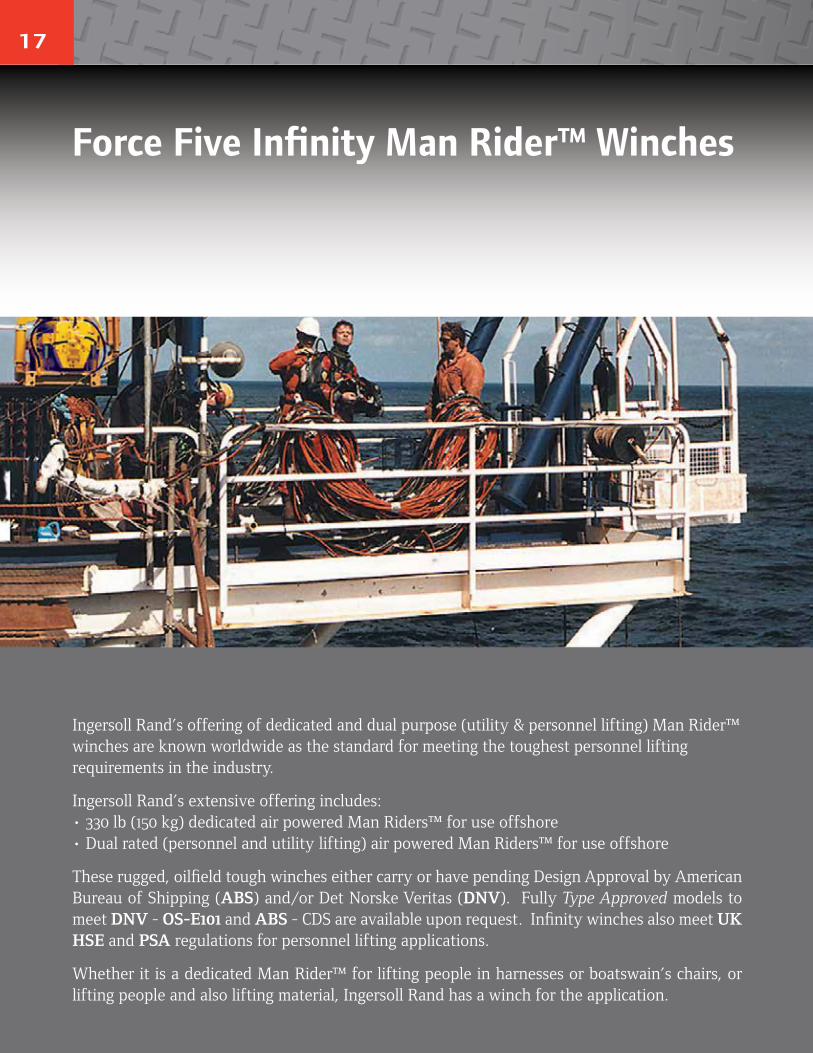
Ingersoll Rand’s offering of dedicated and dual purpose (utility & personnel lifting) Man Rider™ winches are known worldwide as the standard for meeting the toughest personnel lifting requirements in the industry.
Ingersoll Rand’s extensive offering includes: • 330 lb (150 kg) dedicated air powered Man Riders™ for use offshore • Dual rated (personnel and utility lifting) air powered Man Riders™ for use offshore
These rugged, oilfield tough winches either carry or have pending Design Approval by American Bureau of Shipping (ABS) and/or Det Norske Veritas (DNV). Fully Type Approved models to meet DNV - OS-E101 and ABS - CDS are available upon request. Infinity winches also meet UK HSE and PSA regulations for personnel lifting applications.
Whether it is a dedicated Man Rider™ for lifting people in harnesses or boatswain’s chairs, or lifting people and also lifting material, Ingersoll Rand has a winch for the application.
Force Five Infinity Man Rider™ Winches
18
ingersollrandproducts.com/lifting
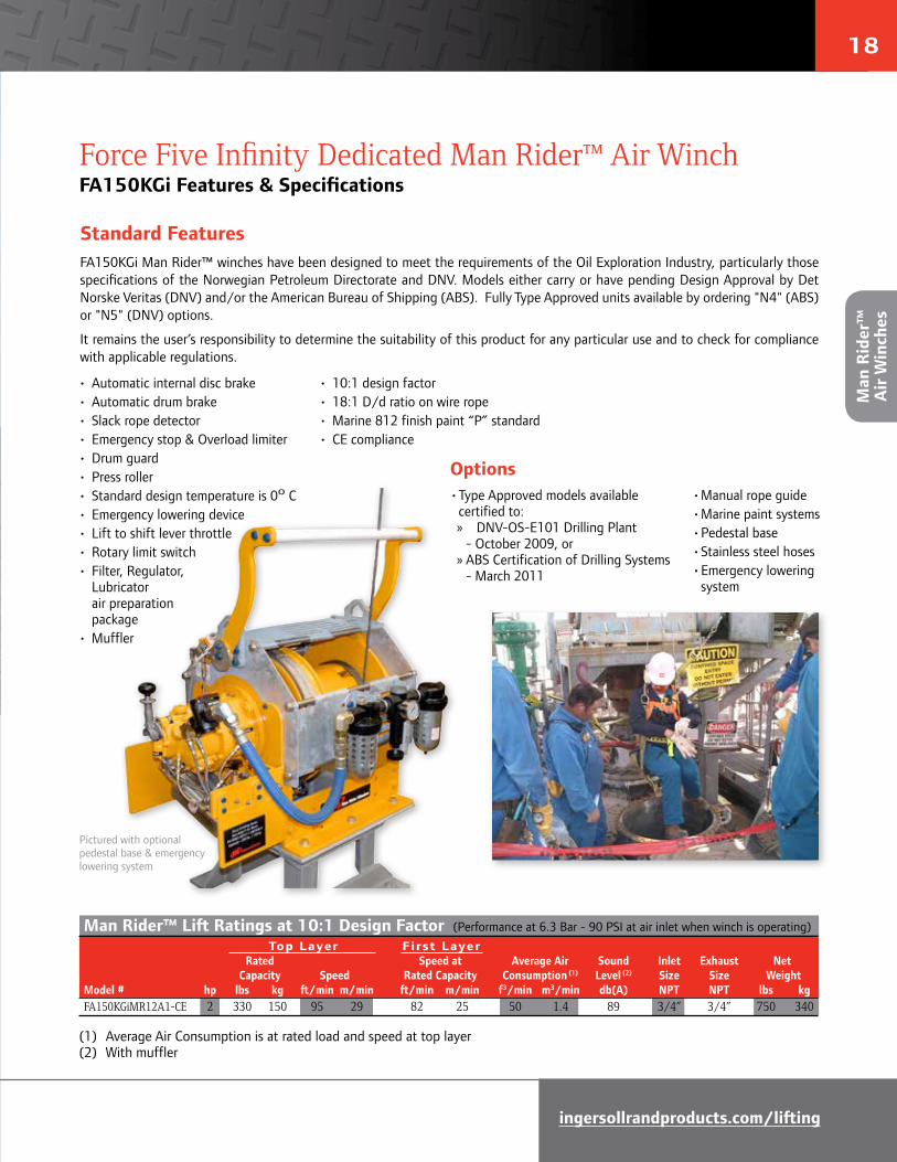
Standard FeaturesFA150KGi Man Rider™ winches have been designed to meet the requirements of the Oil Exploration Industry, particularly those specifications of the Norwegian Petroleum Directorate and DNV. Models either carry or have pending Design Approval by Det Norske Veritas (DNV) and/or the American Bureau of Shipping (ABS). Fully Type Approved units available by ordering "N4" (ABS) or "N5" (DNV) options.
It remains the user’s responsibility to determine the suitability of this product for any particular use and to check for compliance with applicable regulations.
• Automatic internal disc brake• Automatic drum brake• Slack rope detector• Emergency stop & Overload limiter• Drum guard• Press roller• Standard design temperature is 0o C• Emergency lowering device• Lift to shift lever throttle• Rotary limit switch• Filter, Regulator, Lubricator air preparation package• Muffler
• 10:1 design factor• 18:1 D/d ratio on wire rope• Marine 812 finish paint “P” standard• CE compliance
Force Five Infinity Dedicated Man Rider™ Air WinchFA150KGi Features & Specifications
Options
Man Rider™ Lift Ratings at 10:1 Design Factor (Performance at 6.3 Bar - 90 PSI at air inlet when winch is operating) Top Layer First Layer Rated Speed at Average Air Sound Inlet Exhaust Net Capacity Speed Rated Capacity Consumption (1) Level (2) Size Size WeightModel # hp lbs kg ft/min m/min ft/min m/min f3/min m3/min db(A) NPT NPT lbs kgFA150KGiMR12A1-CE 2 330 150 95 29 82 25 50 1.4 89 3/4” 3/4” 750 340
(1) Average Air Consumption is at rated load and speed at top layer(2) With muffler
Pictured with optional pedestal base & emergency lowering system
• Type Approved models available certified to:
» DNV-OS-E101 Drilling Plant - October 2009, or » ABS Certification of Drilling Systems
- March 2011
• Manual rope guide• Marine paint systems• Pedestal base• Stainless steel hoses• Emergency lowering system
Man
Rid
er™
A
ir W
inch
es
19
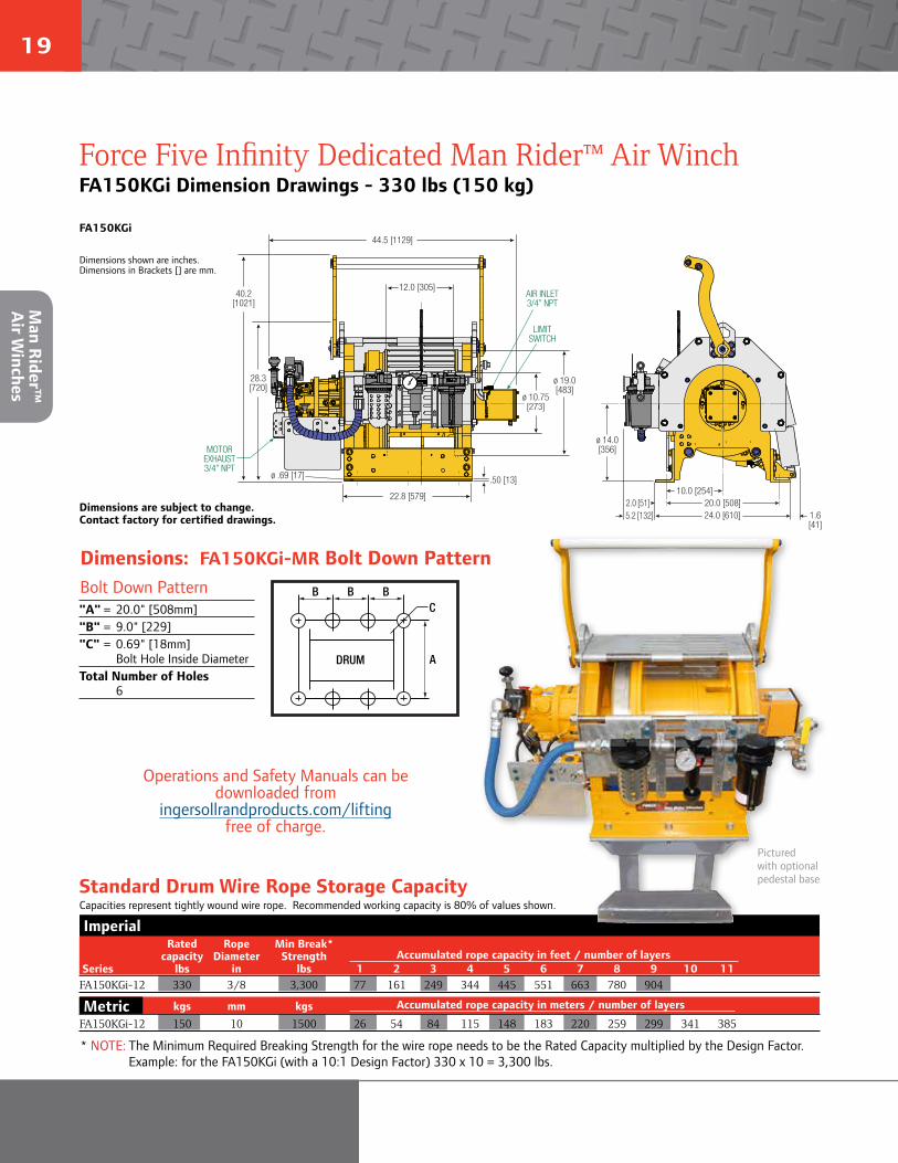
Force Five Infinity Dedicated Man Rider™ Air WinchFA150KGi Dimension Drawings - 330 lbs (150 kg)
10.0 [254]
12.0 [305]
ø 19.0[483]
ø 10.75[273]
22.8 [579]
40.2[1021]
28.3[720]
.50 [13]ø .69 [17]
ø 14.0[356]
20.0 [508]2.0 [51]24.0 [610] 1.6
[41]
AIR INLET3/4” NPT
MOTOR EXHAUST 3/4” NPT
5.2 [132]
44.5 [1129]
LIMITSWITCH
FA150KGi
Dimensions shown are inches.Dimensions in Brackets [] are mm.
Dimensions are subject to change. Contact factory for certified drawings.
Dimensions: FA150KGi-MR Bolt Down Pattern
Operations and Safety Manuals can be downloaded from
ingersollrandproducts.com/lifting free of charge.
DRUM
BB B
A
C
Bolt Down Pattern"A" = 20.0" [508mm]"B" = 9.0" [229]"C" = 0.69" [18mm] Bolt Hole Inside DiameterTotal Number of Holes 6
Pictured with optional pedestal base
Imperial Rated Rope Min Break* capacity Diameter Strength Accumulated rope capacity in feet / number of layers Series lbs in lbs 1 2 3 4 5 6 7 8 9 10 11FA150KGi-12 330 3/8 3,300 77 161 249 344 445 551 663 780 904
Metric kgs mm kgs Accumulated rope capacity in meters / number of layers
FA150KGi-12 150 10 1500 26 54 84 115 148 183 220 259 299 341 385
Standard Drum Wire Rope Storage CapacityCapacities represent tightly wound wire rope. Recommended working capacity is 80% of values shown.
* NOTE: The Minimum Required Breaking Strength for the wire rope needs to be the Rated Capacity multiplied by the Design Factor. Example: for the FA150KGi (with a 10:1 Design Factor) 330 x 10 = 3,300 lbs.
Uti
lity
Air
Win
ches
Man R
ider™
Air W
inches

20
ingersollrandproducts.com/lifting
How to order standard equipmentSpecify complete model code as shown. To order options, use the option code in the option table and add as a suffix to the model code. Example: FA150KGiMR12A1-7ABHR-CE
SeriesFA = Air powered
Personnelcapacity lbs (kg)
150KGi = 330 (150)
Man Rider™MR = Man Rider™
Control1 = Std. winch mounted
Drum length12 = 12 inch
FA 150KGi MR 12 A 1 - 6ABHR-CE
Force Five Infinity Dedicated Man Rider™ Air WinchFA150KGi Model Identification Codes
BrakesA = Automatic drum brake
Options 6 = Drum grooving; specify rope size in sixteenths, e.g.,6 = 6/16" A = Drum guard with manual rope guide B = Winch pedestal base H = Stainless steel hose package for limit switch K = Stowage valve kit installed on winch M1 = Material Traceability per DIN 50049/EN10204 Para 2.2 “Typicals” M2 = Material Traceability per DIN 50049/EN10204 Para 3.1b actuals per product as purchased M3 = Material Traceability per DIN 50049/EN10204 Para 3.1b actuals per product as delivered in final condition N4 (1) = Manufactured under ABS survey N5 (1) = Manufactured under DNV survey P1 = Marine 812-X paint system P2 = Marine 812-X paint system - isocyanate free R = Emergency lowering system (2 liter bottle) W1 = ABS witness test W2 = DNV witness test W3 = LRS witness test W4 = Client witness of load test
-CE = Compliance with the European Machinery Directive
(1) For N4 and N5, refer to page 21
Tip: Emergency lowering.Per regulatory requirements every FA150KGi winch is equipped with an Emergency Lowering Device (ELD) to allow an (end user supplied) auxiliary air supply to be attached to the winch to facilitate emergency lowering in the event the main air supply is lost.
Option “R” (pictured above) is a complete Emergency Lowering System which includes an accumulator tank that serves as the air source during emergency lowering. No end user provided air is required to lower the load and the accumulator is charged during normal winch operation.
➲
(ELD)
Ingersoll Rand strongly recommends using Drum Guards with all winches to prevent inadvertent contact with winch moving parts. Drum Guards are standard for -CE and may be compulsory in some world regions.
Owners and users should always check local regulations and standards before putting a particular product to use.
Man
Rid
er™
A
ir W
inch
es
21
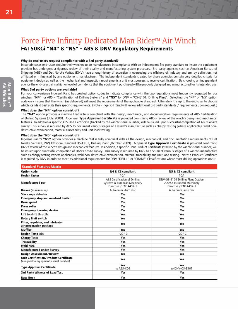
Why do end-users request compliance with a 3rd party standard?In certain cases end-users require their winches to be manufactured in compliance with an independent 3rd party standard to insure the equipment provider has undergone a rigorous review of their quality and manufacturing system processes. 3rd party agencies such as American Bureau of Shipping (ABS) and Det Norske Veritas (DNV) have a long history of expertise in overseeing the offshore oil industry and are, by definition, not affiliated or influenced by any equipment manufacturer. The independent standards created by these agencies contain very detailed criteria for equipment design as well as the mechanical and inspection requirements a unit must possess to receive certification. By choosing an independent agency the end-user gains a higher level of confidence that the equipment purchased will be properly designed and manufactured for its intended use.What 3rd party options are available?For your convenience Ingersoll Rand has created option codes to indicate compliance with the two regulations most frequently requested for our winches; “N4” for ABS – “Certification of Drilling Systems” and “N5” for DNV – “OS-E101, Drilling Plant”. Selecting the “N4” or “N5” option code only insures that the winch (as delivered) will meet the requirements of the applicable Standard. Ultimately it is up to the end-user to choose which standard best suits their specific requirements. (Note - Ingersoll Rand will review additional 3rd party standards / requirements upon request.)What does the “N4” option consist of?The “N4” option provides a machine that is fully compliant with the design, mechanical, and documentation requirements of ABS Certification of Drilling Systems (July 2009). A general Type Approval Certificate is provided confirming ABS's review of the winch’s design and mechanical features. In addition a specific ABS Unit Certificate (tracked by the winch’s serial number) will be issued upon successful completion of ABS's onsite survey. This survey is required by ABS to document various stages of a winch’s manufacture such as charpy testing (where applicable), weld non-destructive examination, material traceability and unit load testing.
What does the “N5” option consist of?Ingersoll Rand’s “N5” option provides a machine that is fully compliant with all the design, mechanical, and documentation requirements of Det Norske Veritas (DNV) Offshore Standard OS-E101, Drilling Plant (October 2009). A general Type Approval Certificate is provided confirming DNV’s review of the winch’s design and mechanical features. In addition, a specific DNV Product Certificate (tracked by the winch’s serial number) will be issued upon successful completion of DNV’s onsite survey. This survey is required by DNV to document various stages of a winch’s manufacture such as charpy testing (where applicable), weld non-destructive examination, material traceability and unit load testing. Note: a Product Certificate is required by DNV in order to meet its additional requirements for DNV "DRILL", or "CRANE" Classifications where most drilling operations occur.
Force Five Infinity Dedicated Man Rider™ Air WinchFA150KGi “N4” & “N5” - ABS & DNV Regulatory Requirements
Option code N4 & CE compliant N5 & CE compliantDesign factor 10:1 10:1
Manufactured per ABS Certification of Drilling DNV-OS-E101 Drilling Plant October
Systems & European Machinery 2009 & European Machinery Directive / EN14492-1 Directive / EN14492-1Brakes (as minimum) Auto drum, Auto disc Auto drum, auto discSlack rope detector Yes Yes Emergency stop and overload limiter Yes Yes Drum guard Yes Yes Press roller Yes Yes Emergency lowering device Yes Yes Lift to shift throttle Yes YesRotary limit switch Yes YesFilter, regulator, and lubricator air preparation package
Yes Yes
Muffler Yes YesDesign Temp (tD) -20° C -20° C Charpy Tests Yes Yes Traceability Yes Yes Weld NDE Yes Yes Manufactured under Survey Yes Yes Design Assessment/Review Yes YesUnit Certification/Product Certificate (assigned to equipment's serial number)
Yes Yes
Type Approval Certificate Yes Yes
to ABS-CDS to DNV-OS-E1013rd Party Witness of Load Test Yes Yes
Data Book Yes Yes
Standard Features Matrix
Man R
ider™
Air W
inches
22
ingersollrandproducts.com/lifting
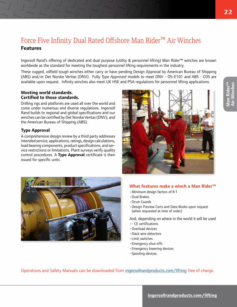
Meeting world standards. Certified to those standards.Drilling rigs and platforms are used all over the world and come under numerous and diverse regulations. Ingersoll Rand builds to regional and global specifications and our winches can be certified by Det Norske Veritas (DNV), and the American Bureau of Shipping (ABS).
Type ApprovalA comprehensive design review by a third party addresses intended service, applications, ratings, design calculations, load bearing components, product specifications, and ser-vice restrictions or limitations. Plant surveys verify quality control procedures. A Type Approval certificate is then issued for specific units.
Force Five Infinity Dual Rated Offshore Man Rider™ Air WinchesFeatures
Ingersoll Rand’s offering of dedicated and dual purpose (utility & personnel lifting) Man Rider™ winches are known worldwide as the standard for meeting the toughest personnel lifting requirements in the industry.These rugged, oilfield tough winches either carry or have pending Design Approval by American Bureau of Shipping (ABS) and/or Det Norske Veritas (DNV). Fully Type Approved models to meet DNV - OS-E101 and ABS - CDS are available upon request. Infinity winches also meet UK HSE and PSA regulations for personnel lifting applications.
What features make a winch a Man Rider™• Minimum design factors of 8:1• Dual Brakes• Drum Guards• Design Preview Certs and Data Books upon request (when requested at time of order)
And, depending on where in the world it will be used• - CE certifications• Overload devices• Slack wire detectors• Limit switches• Emergency shut-offs• Emergency lowering devices• Spooling devices.
Operations and Safety Manuals can be downloaded from ingersollrandproducts.com/lifting free of charge.
Add photo from p21, move current
photo on page
Man
Rid
er™
A
ir W
inch
es

23
Force Five Infinity Dual Rated Offshore Man Rider™ Air WinchesSpecifications & Performance
Tip: It’s an accepted fact that regular maintenance is important in keeping any piece of equipment running at its peak performance. What is often overlooked is maintaining the fuel that powers that same piece of equipment. Whether your equipment is powered by gas, diesel, hydraulic, or air, if the fuel’s quality is affected by dirt, water, or other containments then it is likely you will experience decreased performance and increased maintenance.
An air winch’s air supply must be clean, free from moisture and lubricated to ensure optimum motor performance. Foreign particles, moisture and lack of lubrication are the primary causes of premature motor wear and breakdown. Using an air filter, lubricator, regulator, along with a moisture separator will greatly improve overall product performance and reduce unscheduled downtime.
➲
FA2i-MR12MK1Gwith Optional
Air Preparation Package
Man Rider™ Lift Ratings at 8:1 Design Factor (Performance at 6.3 Bar - 90 PSI at air inlet when winch is operating) Top Layer First Layer Rated Speed at Stall Average Air Sound Inlet Exhaust Net Capacity Speed Rated Capacity Pull Consumption (1) Level (2) Size Size WeightModel # hp lbs kg ft/min m/min ft/min m/min lbs kg f3/min m3/min db(A) NPT NPT lbs kgFA2i-MR24MK1G 9 3,180 1445 75 23 68 21 9,139 4154 280 8 87 1-1/4” 1-1/4” 925 420FA2.5i-MR24MK1G 25 3,180 1445 173 53 145 44 10,277 4671 700 20 97 1-1/4” 2-1/2” 1,265 574FA5i-MR24MK1G 25 6,870 3123 75 23 61 19 23,594 10725 700 20 97 1-1/4” 2-1/2” 2,000 907
Utility Lift Ratings at 5:1 Design Factor (Performance at 6.3 Bar - 90 PSI at air inlet when winch is operating)FA2i-MR24MK1G 9 4,400 2000 51 16 55 17 9,139 4154 280 8 87 1-1/4” 1-1/4” 925 420FA2.5i-MR24MK1G 25 5,000 2273 132 40 128 39 10,277 4671 700 20 97 1-1/4” 2-1/2” 1,265 574FA5i-MR24MK1G 25 11,000 5000 54 16 51 16 23,594 10725 700 20 97 1-1/4” 2-1/2” 2,000 907
(1) Average Air Consumption is at rated load and speed at top layer(2) With optional muffler
Imperial
Standard Drum Wire Rope Storage CapacityCapacities represent tightly wound wire rope. Recommended working capacity is 80% of values shown.
For additional information on calculating Total Drum Storage Capacity and more, please go to: Ingersoll Rand Drum Capacity Estimator - http://www.ingersollrandproducts.com/lifting/winches/drum.htm
* NOTE: The Minimum Required Breaking Strength for the wire rope needs to be the Rated Capacity multiplied by the Design Factor. Example: for the FA2i-MR (with a 8:1 Design Factor) 3,180 x 5 = 25,440 lbs.
Rated Rope Min Break* capacity Diameter Strength Accumulated rope capacity in feet / number of layers Series lbs in lbs 1 2 3 4 5 6 7 8FA2i-MR24 3,180 1/2 25,440 138 289 450 624 809 1,006 1,214 1,435FA2.5i-MR24 3,180 1/2 25,440 138 289 450 624 809 1,006 1,214 1,435FA5i-MR24 6,870 3/4 54,960 128 267 418 581 755 940 1,138 1,346
Metric kgs mm kgs Accumulated rope capacity in meters / number of layers
FA2i-MR24 1445 13 11560 41 86 135 187 242 301 364 430FA2.5i-MR24 1445 13 11560 41 86 135 187 242 301 364 430FA5i-MR24 3123 19 24984 39 81 127 177 230 287 347 410
Man R
ider™
Air W
inches
24
ingersollrandproducts.com/lifting
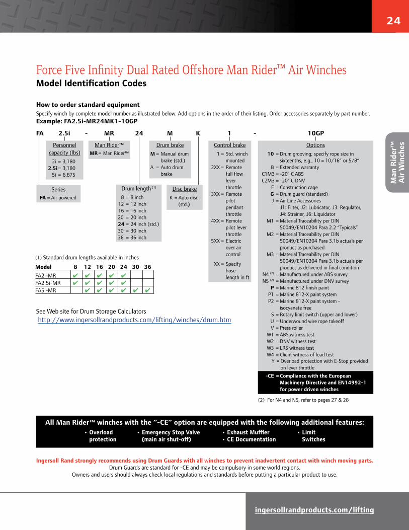
Force Five Infinity Dual Rated Offshore Man Rider™ Air WinchesModel Identification Codes
How to order standard equipmentSpecify winch by complete model number as illustrated below. Add options in the order of their listing. Order accessories separately by part number.Example: FA2.5i-MR24MK1-10GP
Series FA = Air powered
Personnelcapacity (lbs) 2i = 3,180 2.5i = 3,180 5i = 6,875
Man Rider™MR = Man Rider™
Control brake 1 = Std. winch
mounted 2XX = Remote
full flow lever throttle
3XX = Remote pilot pendant throttle
4XX = Remote pilot lever throttle
5XX = Electric over air control
XX = Specify hose length in ft
Disc brakeK = Auto disc (std.)
Options 10 = Drum grooving; specify rope size in sixteenths, e.g., 10 = 10/16” or 5/8” B = Extended warranty C1M3 = -20˚ C ABS C2M3 = -20˚ C DNV E = Construction cage G = Drum guard (standard) J = Air Line Accessories J1: Filter, J2: Lubricator, J3: Regulator, J4: Strainer, J6: Liquidator M1 = Material Traceability per DIN 50049/EN10204 Para 2.2 “Typicals” M2 = Material Traceability per DIN 50049/EN10204 Para 3.1b actuals per product as purchased M3 = Material Traceability per DIN 50049/EN10204 Para 3.1b actuals per product as delivered in final condition N4 (2) = Manufactured under ABS survey N5 (2) = Manufactured under DNV survey P = Marine 812 finish paint P1 = Marine 812-X paint system P2 = Marine 812-X paint system - isocyanate free S = Rotary limit switch (upper and lower) U = Underwound wire rope takeoff V = Press roller W1 = ABS witness test W2 = DNV witness test W3 = LRS witness test W4 = Client witness of load test Y = Overload protection with E-Stop provided on lever throttle
-CE = Compliance with the European Machinery Directive and EN14992-1 for power driven winches
Drum brakeM = Manual drum brake (std.)A = Auto drum brake
FA 2.5i - MR 24 M K 1 - 10GP
All Man Rider™ winches with the “-CE” option are equipped with the following additional features:
Drum length (1)
8 = 8 inch 12 = 12 inch 16 = 16 inch 20 = 20 inch 24 = 24 inch (std.) 30 = 30 inch 36 = 36 inch
(2) For N4 and N5, refer to pages 27 & 28
(1) Standard drum lengths available in inches
Model 8 12 16 20 24 30 36FA2i-MR 4 4 4 4 4
FA2.5i-MR 4 4 4 4 4
FA5i-MR 4 4 4 4 4 4
See Web site for Drum Storage Calculators http://www.ingersollrandproducts.com/lifting/winches/drum.htm
• Overload protection
• Emergency Stop Valve (main air shut-off)
• Exhaust Muffler• CE Documentation
• Limit Switches
Ingersoll Rand strongly recommends using Drum Guards with all winches to prevent inadvertent contact with winch moving parts. Drum Guards are standard for -CE and may be compulsory in some world regions.
Owners and users should always check local regulations and standards before putting a particular product to use.
Man
Rid
er™
A
ir W
inch
es

25
Force Five Infinity Dual Rated Offshore Man Rider™ Air WinchesDimension Drawings - FA2i-MR24MK1G & FA2.5i-MR24MK1G
Dimensions are subject to change. Contact factory for certified drawings.
FA2i-MR12MK1G FA2i-MR24MK1G with disc and manual brake
3,180 lbs (1445 kg)
Dimensions shown are inches.Dimensions in Brackets [] are mm.
FA2.5i-MR12MK1G FA2.5i-MR24MK1G with disc andmanual brake
3,180 lbs (1445 kg)
Dimensions shown are inches.Dimensions in Brackets [] are mm.
33.0[839]
ø 10.75[273]
ø 19.0[483]
.5 [13]ø .69 [17]
4.9 [125]
20.0 [508]
10.0[254]
24.0 [610]
ø 14.0[356]
2.0 [51]
Overall Length
Drum Length
Base Length
AIR INLET 1-1/4” NPT
MOTOR EXHAUST
2-1/2” NPT
FA2.5i - MR-MK1
LIMITSWITCH
8.4 [213]
Overall Base Bolt Down Total Number Length Length "B" Dimension of Holes Drum Drum & Disc Drum & Disc Drum & Disc Drum & Disc Length Brakes Brakes Brakes Brakes in mm in mm in mm in mm 8 203 36.8 935 18.8 478 7.0 178 6 12 305 40.8 1036 22.8 579 9.0 191 6 16 406 44.8 1138 26.8 681 7.5 159 8 20 508 48.8 1240 30.8 782 9.0 197 8 24 610 52.8 1341 34.8 884 10.0 229 8
DRUM
BB B
A
CBolt Down Pattern"A" = 20" [508mm]"B" = See (Left) chart"C" = 0.69" [18mm] Bolt Hole Inside Diameter
Dimensions: FA2i-MR and Bolt Down Pattern
Overall Base Bolt Down Total Number Length Length "B" Dimension of Holes Drum Drum & Disc Drum & Disc Drum & Disc Drum & Disc Length Brakes Brakes Brakes Brakes in mm in mm in mm in mm 8 203 36 914 18.8 478 7.0 178 6 12 305 46 1168 22.8 579 9.0 191 6 16 406 50 1270 26.8 681 7.5 159 8 20 508 54 1372 30.8 782 9.0 197 8 24 610 58 1473 34.8 884 10.0 229 8
DRUM
BB B
A
CBolt Down Pattern"A" = 20" [508mm]"B" = See (Left) chart"C" = 0.69" [18mm] Bolt Hole Inside Diameter
Dimensions: FA2.5i-MR and Bolt Down Pattern
33.0[839]
ø 10.75[273]
ø 19.0[483]
.5 [13]ø .69 [17]
4.9 [125]
20.0 [508]
10.0[254]
24.0 [610]
ø 14.0[356]
2.0 [51]
Overall Length
Drum Length
Base Length
AIR INLET 1-1/4” NPT
MOTOR EXHAUST
2-1/2” NPT
FA2.5i - MR-MK1
LIMITSWITCH
8.4 [213]
*
28.4[723]
ø 10.75[273]
ø 19.0[483]
.5 [13]ø .69 [17]
4.9 [125]
20.0 [508]
10.0[254]
24.0 [610]
ø 14.0[356]
2.0 [51]
FA2i - MK1G
Overall Length
Drum Length
Base Length
AIR INLET 1-1/4” NPT
MOTOR EXHAUST
1-1/4” NPT
LIMITSWITCH
8.4 [213]
*
NOTE: * Limit Switches standard on -CE versions only.
Man R
ider™
Air W
inches

26
ingersollrandproducts.com/lifting
FA5i-MR16MK1G FA5i-MR24MK1G with disc and manual brake
6,875 lbs (3125 kg)
Dimensions shown are inches.Dimensions in Brackets [] are mm.
Dimensions are subject to change. Contact factory for certified drawings.
Force Five Infinity Dual Rated Offshore Man Rider™ Air WinchesDimension Drawings - FA5i-MR24MK1G
Overall Base Bolt Down Total Number Length Length "B" Dimension of Holes Drum Drum & Disc Drum & Disc Drum & Disc Drum & Disc Length Brakes Brakes Brakes Brakes in mm in mm in mm in mm 12 305 47.6 1209 24.3 617 7.5 191 6 16 406 51.6 1311 28.3 719 9.0 191 6 20 508 55.6 1412 32.3 820 10.0 159 8 24 610 59.6 1514 36.3 922 10.5 197 8 30 762 65.6 1666 42.3 1074 10.0 229 8 36 914 71.6 1819 48.3 1227 11.0 229 10
DRUM
BB B
A
C
Bolt Down Pattern"A" = 31.25" [795mm]"B" = See (above) chart"C" = 0.81" [21mm] Bolt Hole Inside Diameter
Dimensions: FA5i-MR and Bolt Down Pattern
FA2.5i-MR12MK1PY
36.5[928]
ø 15.0[381] ø 27.0
[686]
.75 [19]ø .81 [21]
2.7 [68]31.26 [794]
15.6 [397]
35.0 [889]
ø 17.5[444]
1.9 [47]
FA5i - MR-MK1G
Overall Length
Drum Length
Base Length
AIR INLET 1-1/4” NPT
MOTOR EXHAUST
2-1/2” NPT
8.4 [213]
LIMITSWITCH
36.5[928]
ø 15.0[381] ø 27.0
[686]
.75 [19]ø .81 [21]
2.7 [68]31.26 [794]
15.6 [397]
35.0 [889]
ø 17.5[444]
1.9 [47]
FA5i - MR-MK1G
Overall Length
Drum Length
Base Length
AIR INLET 1-1/4” NPT
MOTOR EXHAUST
2-1/2” NPT
8.4 [213]
LIMITSWITCH*
NOTE: * Limit Switches standard on -CE versions only.
Man
Rid
er™
A
ir W
inch
es
27
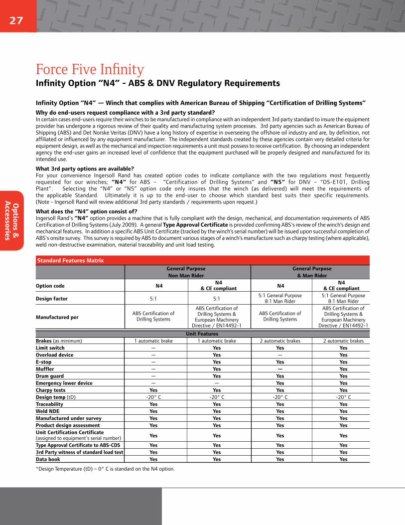
Infinity Option “N4” — Winch that complies with American Bureau of Shipping “Certification of Drilling Systems”Why do end-users request compliance with a 3rd party standard?In certain cases end-users require their winches to be manufactured in compliance with an independent 3rd party standard to insure the equipment provider has undergone a rigorous review of their quality and manufacturing system processes. 3rd party agencies such as American Bureau of Shipping (ABS) and Det Norske Veritas (DNV) have a long history of expertise in overseeing the offshore oil industry and are, by definition, not affiliated or influenced by any equipment manufacturer. The independent standards created by these agencies contain very detailed criteria for equipment design, as well as the mechanical and inspection requirements a unit must possess to receive certification. By choosing an independent agency the end-user gains an increased level of confidence that the equipment purchased will be properly designed and manufactured for its intended use.
What 3rd party options are available?For your convenience Ingersoll Rand has created option codes to indicate compliance with the two regulations most frequently requested for our winches; “N4” for ABS – “Certification of Drilling Systems” and “N5” for DNV – “OS-E101, Drilling Plant”. Selecting the “N4” or “N5” option code only insures that the winch (as delivered) will meet the requirements of the applicable Standard. Ultimately it is up to the end-user to choose which standard best suits their specific requirements. (Note - Ingersoll Rand will review additional 3rd party standards / requirements upon request.)
What does the “N4” option consist of?Ingersoll Rand's “N4” option provides a machine that is fully compliant with the design, mechanical, and documentation requirements of ABS Certification of Drilling Systems (July 2009). A general Type Approval Certificate is provided confirming ABS's review of the winch’s design and mechanical features. In addition a specific ABS Unit Certificate (tracked by the winch’s serial number) will be issued upon successful completion of ABS's onsite survey. This survey is required by ABS to document various stages of a winch’s manufacture such as charpy testing (where applicable), weld non-destructive examination, material traceability and unit load testing.
*Design Temperature (tD) – 0° C is standard on the N4 option.
Standard Features Matrix
General Purpose General Purpose Non Man Rider & Man Rider
Option code N4 N4 N4 N4 & CE compliant & CE compliant
Design factor 5:1 5:1 5:1 General Purpose 5:1 General Purpose 8:1 Man Rider 8:1 Man Rider
Manufactured per
ABS Certification of
ABS Certification of ABS Certification of
ABS Certification of
Drilling Systems Drilling Systems &
Drilling Systems Drilling Systems &
European Machinery European Machinery Directive / EN14492-1 Directive / EN14492-1
Unit Features Brakes (as minimum) 1 automatic brake 1 automatic brake 2 automatic brakes 2 automatic brakesLimit switch — Yes Yes YesOverload device — Yes — YesE-stop — Yes Yes YesMuffler — Yes — YesDrum guard — Yes Yes YesEmergency lower device — — Yes YesCharpy tests Yes Yes Yes YesDesign temp (tD) -20° C -20° C -20° C -20° CTraceability Yes Yes Yes YesWeld NDE Yes Yes Yes YesManufactured under survey Yes Yes Yes YesProduct design assessment Yes Yes Yes YesUnit Certification Certificate (assigned to equipment's serial number) Yes Yes Yes Yes
Type Approval Certificate to ABS-CDS Yes Yes Yes Yes3rd Party witness of standard load test Yes Yes Yes YesData book Yes Yes Yes Yes
Force Five InfinityInfinity Option “N4” - ABS & DNV Regulatory Requirements
Options &
A
ccessories
28
ingersollrandproducts.com/lifting
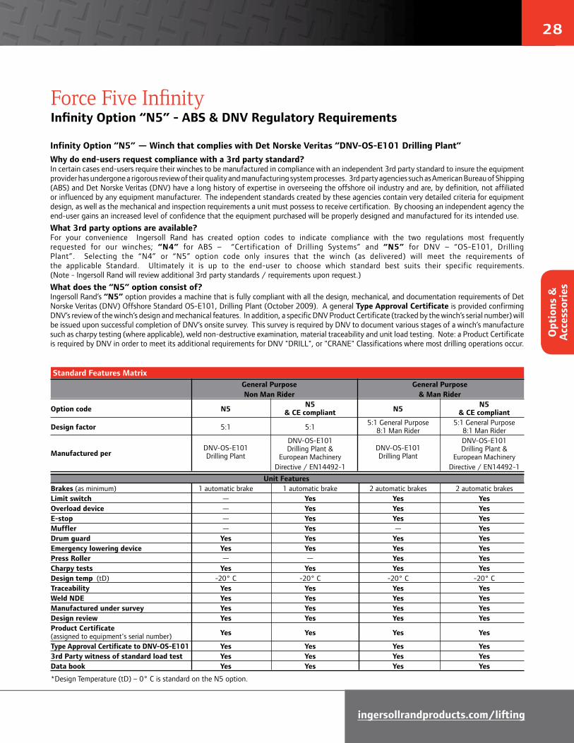
Infinity Option “N5” — Winch that complies with Det Norske Veritas “DNV-OS-E101 Drilling Plant”Why do end-users request compliance with a 3rd party standard?In certain cases end-users require their winches to be manufactured in compliance with an independent 3rd party standard to insure the equipment provider has undergone a rigorous review of their quality and manufacturing system processes. 3rd party agencies such as American Bureau of Shipping (ABS) and Det Norske Veritas (DNV) have a long history of expertise in overseeing the offshore oil industry and are, by definition, not affiliated or influenced by any equipment manufacturer. The independent standards created by these agencies contain very detailed criteria for equipment design, as well as the mechanical and inspection requirements a unit must possess to receive certification. By choosing an independent agency the end-user gains an increased level of confidence that the equipment purchased will be properly designed and manufactured for its intended use.What 3rd party options are available?For your convenience Ingersoll Rand has created option codes to indicate compliance with the two regulations most frequently requested for our winches; “N4” for ABS – “Certification of Drilling Systems” and “N5” for DNV – “OS-E101, Drilling Plant”. Selecting the “N4” or “N5” option code only insures that the winch (as delivered) will meet the requirements of the applicable Standard. Ultimately it is up to the end-user to choose which standard best suits their specific requirements. (Note - Ingersoll Rand will review additional 3rd party standards / requirements upon request.)What does the “N5” option consist of?Ingersoll Rand’s “N5” option provides a machine that is fully compliant with all the design, mechanical, and documentation requirements of Det Norske Veritas (DNV) Offshore Standard OS-E101, Drilling Plant (October 2009). A general Type Approval Certificate is provided confirming DNV’s review of the winch’s design and mechanical features. In addition, a specific DNV Product Certificate (tracked by the winch’s serial number) will be issued upon successful completion of DNV’s onsite survey. This survey is required by DNV to document various stages of a winch’s manufacture such as charpy testing (where applicable), weld non-destructive examination, material traceability and unit load testing. Note: a Product Certificate is required by DNV in order to meet its additional requirements for DNV "DRILL", or "CRANE" Classifications where most drilling operations occur.
*Design Temperature (tD) – 0° C is standard on the N5 option.
Standard Features Matrix
General Purpose General Purpose Non Man Rider & Man Rider
Option code N5 N5 N5 N5 & CE compliant & CE compliant
Design factor 5:1 5:1 5:1 General Purpose 5:1 General Purpose 8:1 Man Rider 8:1 Man Rider
Manufactured per
DNV-OS-E101
DNV-OS-E101 DNV-OS-E101
DNV-OS-E101
Drilling Plant Drilling Plant &
Drilling Plant Drilling Plant &
European Machinery European Machinery Directive / EN14492-1 Directive / EN14492-1
Unit Features Brakes (as minimum) 1 automatic brake 1 automatic brake 2 automatic brakes 2 automatic brakesLimit switch — Yes Yes YesOverload device — Yes Yes YesE-stop — Yes Yes YesMuffler — Yes — YesDrum guard Yes Yes Yes YesEmergency lowering device Yes Yes Yes YesPress Roller — — Yes YesCharpy tests Yes Yes Yes YesDesign temp (tD) -20° C -20° C -20° C -20° CTraceability Yes Yes Yes YesWeld NDE Yes Yes Yes YesManufactured under survey Yes Yes Yes YesDesign review Yes Yes Yes YesProduct Certificate (assigned to equipment's serial number) Yes Yes Yes Yes
Type Approval Certificate to DNV-OS-E101 Yes Yes Yes Yes3rd Party witness of standard load test Yes Yes Yes YesData book Yes Yes Yes Yes
Force Five InfinityInfinity Option “N5” - ABS & DNV Regulatory Requirements
Opt
ions
&
Acc
esso
ries
29
LIMITSWITCH
EXHAUST MUFFLERS
AUTO DISC BRAKE
AUTO DRUM BRAKE
DRUM GUARD
OVERLOAD VALVE
EMERGENCY STOP VALVE
AUTO DRUM BRAKE
2
3
5
6
1
4
7
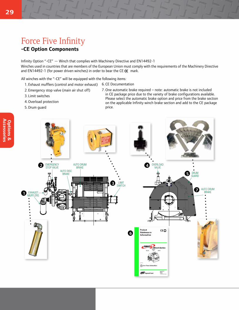
All winches with the “-CE” will be equipped with the following items:1. Exhaust mufflers (control and motor exhaust)2. Emergency stop valve (main air shut off)3. Limit switches4. Overload protection5. Drum guard
Infinity Option “-CE” — Winch that complies with Machinery Directive and EN14492-1Winches used in countries that are members of the European Union must comply with the requirements of the Machinery Directive and EN14492-1 (for power driven winches) in order to bear the CE mark.
Force Five Infinity-CE Option Components
6. CE Documentation7. One automatic brake required – note: automatic brake is not included
in CE package price due to the variety of brake configurations available. Please select the automatic brake option and price from the brake section on the applicable Infinity winch brake section and add to the CE package price.
Options &
A
ccessories
30
ingersollrandproducts.com/lifting
Force Five InfinityOptions Information
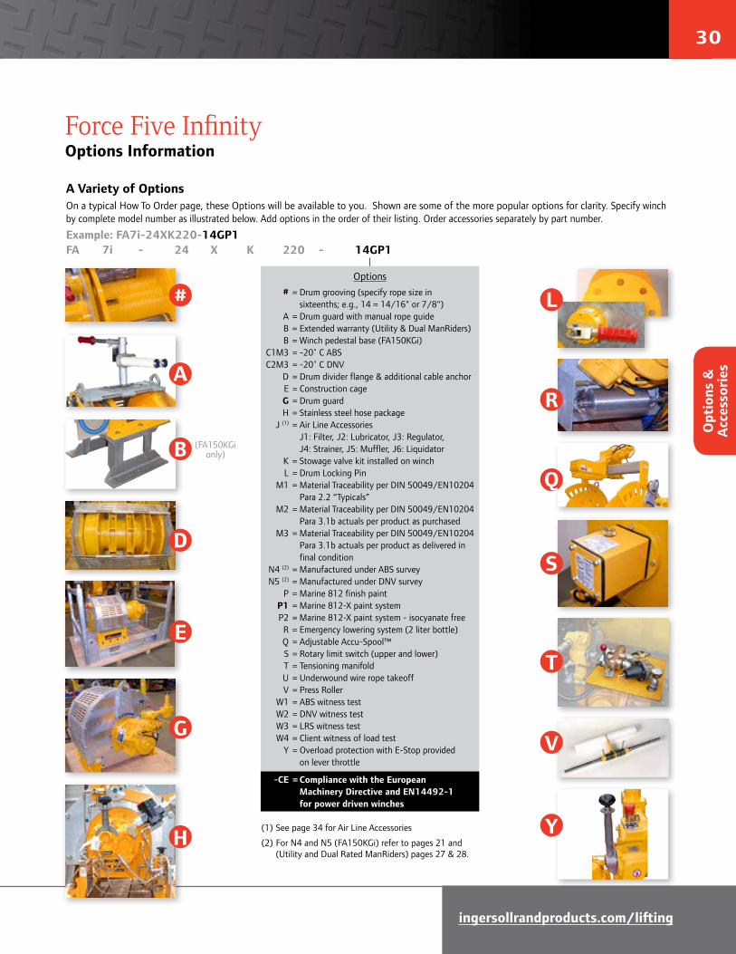
A Variety of OptionsOn a typical How To Order page, these Options will be available to you. Shown are some of the more popular options for clarity. Specify winch by complete model number as illustrated below. Add options in the order of their listing. Order accessories separately by part number.
Example: FA7i-24XK220-14GP1FA 7i - 24 X K 220 - 14GP1
(1) See page 34 for Air Line Accessories
(2) For N4 and N5 (FA150KGi) refer to pages 21 and (Utility and Dual Rated ManRiders) pages 27 & 28.
Options # = Drum grooving (specify rope size in sixteenths; e.g., 14 = 14/16" or 7/8") A = Drum guard with manual rope guide B = Extended warranty (Utility & Dual ManRiders) B = Winch pedestal base (FA150KGi) C1M3 = -20˚ C ABS C2M3 = -20˚ C DNV D = Drum divider flange & additional cable anchor E = Construction cage G = Drum guard H = Stainless steel hose package J (1) = Air Line Accessories J1: Filter, J2: Lubricator, J3: Regulator, J4: Strainer, J5: Muffler, J6: Liquidator K = Stowage valve kit installed on winch L = Drum Locking Pin M1 = Material Traceability per DIN 50049/EN10204 Para 2.2 “Typicals” M2 = Material Traceability per DIN 50049/EN10204 Para 3.1b actuals per product as purchased M3 = Material Traceability per DIN 50049/EN10204 Para 3.1b actuals per product as delivered in final condition N4 (2) = Manufactured under ABS survey N5 (2) = Manufactured under DNV survey P = Marine 812 finish paint P1 = Marine 812-X paint system P2 = Marine 812-X paint system - isocyanate free R = Emergency lowering system (2 liter bottle) Q = Adjustable Accu-Spool™ S = Rotary limit switch (upper and lower) T = Tensioning manifold U = Underwound wire rope takeoff V = Press Roller W1 = ABS witness test W2 = DNV witness test W3 = LRS witness test W4 = Client witness of load test Y = Overload protection with E-Stop provided on lever throttle
-CE = Compliance with the European Machinery Directive and EN14492-1 for power driven winches
#
A
B
D
E
G
H
L
R
Q
S
T
V
Y
(FA150KGi only)
Opt
ions
&
Acc
esso
ries

31
This updated remote control allows unlimited distance between the operator and winch or hoist without the excessive pressure drops, quick exhaust valves and resultant delays found in air control lines. On pendant controls, dialing-in an electrical setting determines the speed. Push buttons provide pay-in or pay-out. For variable speed control, the control buttons are depressed and the dial-in knob provides proportional control. The joystick lever control provides traditional winch style variable speed in a hand held or wall mounted control box.
Standard Features• Portable, easy to hold control pendent• NEMA 4 control box and pendent• Holding down the control button and turning the Dial-In control provides variable speed• Automatic return-to-center when joystick is released• Emergency stop button on control enclosure• Unlimited control length• Requires pilot control valve chest for field retrofit• Adaptable to most winch models and Hercu-Link hoists E/A-PCS150 shown with
150 ft (46 m) of control cable
Pendent Control
E-Stop
Dial-in speed control
Control buttons
Joystick lever type control
Variable speed lever
E-stop
Force Five InfinityElectric-Over-Air Pendant Control System
Optional pendant for secondary local control
Opt
ions
&
Acc
esso
riesO
ptions &
Accessories
32
ingersollrandproducts.com/lifting
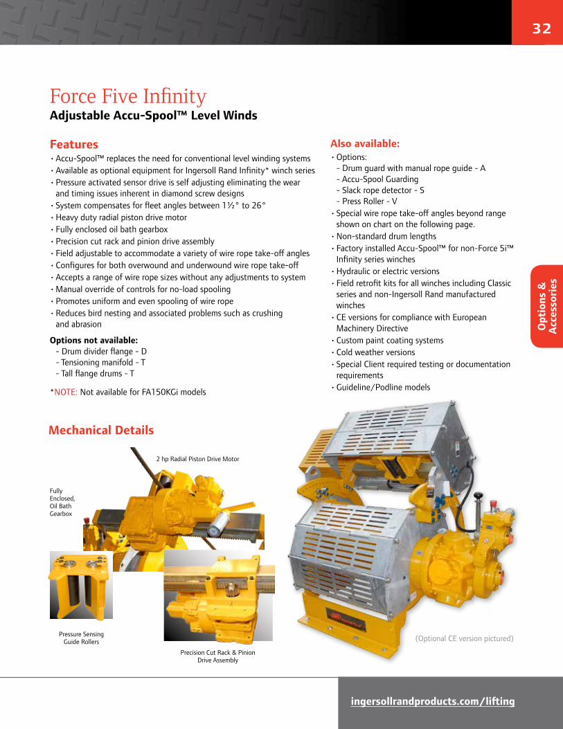
Precision Cut Rack & Pinion Drive Assembly
Fully Enclosed, Oil Bath Gearbox
2 hp Radial Piston Drive Motor
Pressure Sensing Guide Rollers
Mechanical Details
(Optional CE version pictured)
Features• Accu-Spool™ replaces the need for conventional level winding systems• Available as optional equipment for Ingersoll Rand Infinity* winch series• Pressure activated sensor drive is self adjusting eliminating the wear and timing issues inherent in diamond screw designs• System compensates for fleet angles between 1½° to 26°• Heavy duty radial piston drive motor• Fully enclosed oil bath gearbox• Precision cut rack and pinion drive assembly• Field adjustable to accommodate a variety of wire rope take-off angles• Configures for both overwound and underwound wire rope take-off• Accepts a range of wire rope sizes without any adjustments to system• Manual override of controls for no-load spooling• Promotes uniform and even spooling of wire rope• Reduces bird nesting and associated problems such as crushing and abrasion
Options not available: - Drum divider flange - D - Tensioning manifold - T - Tall flange drums - T
*NOTE: Not available for FA150KGi models
Force Five InfinityAdjustable Accu-Spool™ Level Winds
Also available: • Options: - Drum guard with manual rope guide - A - Accu-Spool Guarding - Slack rope detector - S - Press Roller - V• Special wire rope take-off angles beyond range shown on chart on the following page.• Non-standard drum lengths• Factory installed Accu-Spool™ for non-Force 5i™ Infinity series winches• Hydraulic or electric versions• Field retrofit kits for all winches including Classic series and non-Ingersoll Rand manufactured winches• CE versions for compliance with European Machinery Directive• Custom paint coating systems• Cold weather versions• Special Client required testing or documentation requirements• Guideline/Podline models
Opt
ions
&
Acc
esso
ries

33
90100110
120
130
140
150
160
170
180
190
200
210
220
230
240250
260 270 280290
300
310
320
330340
3500
1020
3040
5060
7080Overwound 342 o (-18) - 95
o
90100110
120
130
140
150
160
170
180
190
200
210
220
230
240250
260 270 280290
300
310
320
330340
3500
1020
3040
5060
7080
Underwound 25 o - 120 o
Underwound
(Base)
Motor end
Overwound
(Base)
Motor end
How To Order• Begin with the base model driver and pricing of the Force Five Infinity series winch you have selected.
NOTE: *manual drum brakes are not available with adjustable Accu-Spool™ level wind.
• Add the model driver option code: “Q” to the your winch model.
NOTE: If the desired wire rope take-off angle is provided at time of an order the adjustable Accu-Spool™ will be preset for this angle prior to shipment. Otherwise the setting will be at the discretion of the factory.
*To prevent inadvertent contact with moving parts only automatic brakes are available on adjustable Accu-Spool™ level winds.
** Not all standard Force Five Infinity series winch options are compatible with the Accu-Spool™ level wind due to mechanical or regulatory issues.
Adjustable Accu-Spool™ wire rope take-off range
Force Five InfinityAdjustable Accu-Spool™ Level Winds
Options &
A
ccessories

34
ingersollrandproducts.com/lifting
Force Five Infinity AccessoriesAir Line Accessories
Model Filter driver J1 Lubricator driver J2 Regulator J3 Part # Inlet Part # Inlet Regulator Inlet Regulator Gauge size size w/Gauge (1) size Only Only FA2i F35461-410 1" L36461-110 1" 382-35597 1" R37561-100 104502 FA2.5i F35581-410 1-1/2" L36581-110 1-1/2" 382-35598 1-1/2" R37581-100 104502 FA5i F35581-410 1-1/2" L36581-110 1-1/2" 382-35598 1-1/2" R37581-100 104502 FA5Ti F35581-410 1-1/2" L36581-110 1-1/2" 382-35598 1-1/2" R37581-100 104502 FA7i F35581-410 1-1/2" L36581-110 1-1/2" 382-35598 1-1/2" R37581-100 104502 FA7Ti F35581-410 1-1/2" L36581-110 1-1/2" 382-35598 1-1/2" R37581-100 104502 FA10i F35581-410 1-1/2" L36581-110 1-1/2" 382-35598 1-1/2" R37581-100 104502 FA7Ti-GL42 F35581-410 1-1/2" L36581-110 1-1/2" 382-35598 1-1/2" R37581-100 104502 FA7Ti-PL42 F35581-410 1-1/2" L36581-110 1-1/2" 382-35598 1-1/2" R37581-100 104502 FA150KGi-MR F35561-411 1" L36561-100 1" N/A 1" R37561-100 43806249
Model Strainer J4 Muffler J5* Liquidator J6 Part # Inlet size Kit # Part # Inlet size Part # Inlet size FA2i HU-A267AT 1" 382-29922 (2) 52465 (2 per kit) 1-1/4" — Design Required — 382-36314 (3) (4) 52465 (2 per kit) 1-1/4" FA2.5i K4U-A267AT 1-1/4" 24375 (5) 50594 u 2" 8834-W1-000 2" 52472 v 1-1/2" FA5i K4U-A267AT 1-1/4" 24375 (5) 50594 u 2" 8834-W1-000 2" 52472 v 1-1/2" FA5Ti K4U-A267AT 1-1/4" 24375 (5) 50594 u 2" 8834-W1-000 2" 52472 v 1-1/2" FA7i K4U-A267AT 1-1/4" 24375 (5) 50594 u 2" 8834-W1-000 2" 52472 v 1-1/2" FA7Ti K4U-A267AT 1-1/4" 24375 (5) 50594 u 2" 8834-W1-000 2" 52472 v 1-1/2" FA10i K4U-A267AT 1-1/4" 24375 (5) 50594 u 2" 8834-W1-000 2" 52472 v 1-1/2" FA7Ti-GL42 K4U-A267AT 1-1/4" 24375 (5) 50594 u 2" 8834-W1-000 2" 52472 v 1-1/2" FA7Ti-PL42 K4U-A267AT 1-1/4" 24375 (5) 50594 u 2" 8834-W1-000 2" 52472 v 1-1/2" FA150KGi-MR — Contact Factory — 52104 3/4" — Contact Factory —
Continued
* Standard on -E models • (1) All Regulators "J3" options ship with a gauge installed • (2) Standard throttle lever • (3) 3XX remote pilot pendent(4) 4XX remote pilot lever throttle • (5) Fits all throttle options
Lubricator, Regulator, FilterControl Exhaust (top) and Motor Exhaust (bottom)
u
v
NOTE: For protection during shipment and due to the wide range of installation variables the air line accessories are not installed on the units at the factory. All “J” accessories are shipped loose for client installation. While no mounting hardware is supplied to attached accessories to the winch some basic fittings are included to facilitate assembly of the selected “J” option accessories to one another.
Opt
ions
&
Acc
esso
ries
35
Force Five InfinityTech Tips and Drawings
Technical support is an integral part of the Total System Solution philosophy that Ingersoll Rand is dedicated to providing. The following pages contain useful technical information to assist in the selection of high capacity hoists and winches.
For regular updates and additions, please go to www.ingersollrandproducts.com. Select your global region. Select Products & Services > Lifting/Material Handling > Winches > Winch Selection Support for:
• Drum Capacity Estimator program: Plug in your numbers to determine the amount of wire rope a given size drum can hold.
• Fleet Angle Calculator: Distance from winch drum to sheave.
• Horizontal Load Reversing Capacity Estimator: Calculates length of drum required to move a load a given distance.
• Winch & Hoist Checklist: Interactive checklist designed to gather information to determine your material handling needs.
• Winch and Hoist Options: Detailed descriptions and benefits of various options for Ingersoll Rand hoists and winches
• Winch and Hoist Solutions: Overviews and photos of engineered custom products not found in this catalog
• Wire Rope Selection: Wire rope recommendations
• Drawings: Outline dimensional drawings for many specific models are shown, including models with all options required by the European Machinery Directive; - suffix “-CE” option code on their product family pages.
For instance, for Force Five Infinity Winch Drawings, select Winches > Air Winches > Force 5i™ Infinity Winch Series. Scroll down to the Document Library and select the Outline Drawing tab.
Please contact Ingersoll Rand Tech Support at (253) 398-3900 or email WinchandHoistSolutions.com if a drawing you need is not listed.
Tech Tips &
Draw
ings

36
ingersollrandproducts.com/lifting
Ingersoll Rand Limited WarrantyIngersoll Rand Company (“IR”) warrants to the original user its material handling products (“Products”) to be free of defects in material and workmanship for a period of one year from the date of purchase. IR will, at its option either (1) repair, without cost, any Product found to be defective, including parts and labor charges, or (2) replace such Products or refund the purchase price, less a reasonable allowance for depreciation, in exchange for the Product. Repairs or replacements are warranted for the remainder of the original warranty.
If any Product proves defective within its original one-year warranty period, it should be returned to any Authorized Product Service Distributor, transportation prepaid with proof of purchase or warranty card. This warranty does not apply to Products which IR has determined to have been misused or abused, improperly maintained by the user, or where the malfunction or defect can be attributed to the use of non-genuine IR repair parts.
Force Five InfinityWarranty Information
IR MAKES NO OTHER WARRANTY, CONDITION OR REPRESENTATION OF ANY KIND WHATSOEVER, EXPRESSED OR IMPLIED, STATUTORY OR OTHERWISE, AND ALL IMPLIED WARRANTIES AND CONDITIONS RELATING TO MERCHANTABILITY AND FITNESS FOR A PARTICULAR PURPOSE, ARE HEREBY DISCLAIMED.
IR’s maximum liability is limited to the purchase price of the Product and in no event shall IR be liable for any consequential, indirect incidental or special damages of any nature arising from the sale or use of the Product, whether in contract, tort or otherwise.
Note: Some states do not allow limitations on incidental or consequential damages, so that the above limitations may not apply to you. This warranty gives you specific legal rights and you may also have other rights which may vary from state to state.
Fulcrum series electric winch, product code 405-002: 2 year warranty.
War
rant
y In
form
atio
n
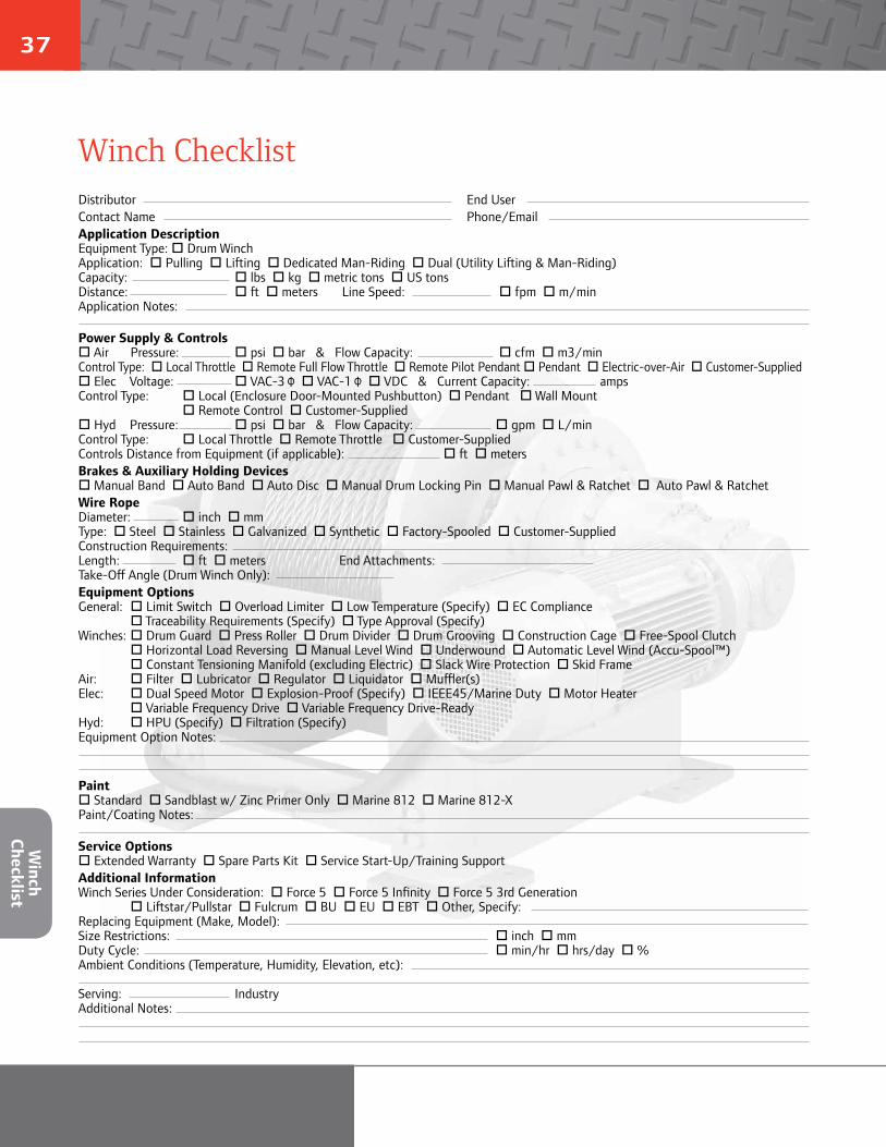
37
Winch ChecklistDistributor End User Contact Name Phone/Email Application DescriptionEquipment Type: Drum WinchApplication: Pulling Lifting Dedicated Man-Riding Dual (Utility Lifting & Man-Riding)Capacity: lbs kg metric tons US tonsDistance: ft meters Line Speed: fpm m/minApplication Notes: Power Supply & Controls Air Pressure: psi bar & Flow Capacity: cfm m3/minControl Type: Local Throttle Remote Full Flow Throttle Remote Pilot Pendant Pendant Electric-over-Air Customer-Supplied Elec Voltage: VAC-3 Φ VAC-1 Φ VDC & Current Capacity: ampsControl Type: Local (Enclosure Door-Mounted Pushbutton) Pendant Wall Mount Remote Control Customer-Supplied Hyd Pressure: psi bar & Flow Capacity: gpm L/minControl Type: Local Throttle Remote Throttle Customer-SuppliedControls Distance from Equipment (if applicable): ft metersBrakes & Auxiliary Holding Devices Manual Band Auto Band Auto Disc Manual Drum Locking Pin Manual Pawl & Ratchet Auto Pawl & RatchetWire RopeDiameter: inch mm Type: Steel Stainless Galvanized Synthetic Factory-Spooled Customer-SuppliedConstruction Requirements: Length: ft meters End Attachments: Take-Off Angle (Drum Winch Only): Equipment OptionsGeneral: Limit Switch Overload Limiter Low Temperature (Specify) EC Compliance Traceability Requirements (Specify) Type Approval (Specify)Winches: Drum Guard Press Roller Drum Divider Drum Grooving Construction Cage Free-Spool Clutch Horizontal Load Reversing Manual Level Wind Underwound Automatic Level Wind (Accu-Spool™) Constant Tensioning Manifold (excluding Electric) Slack Wire Protection Skid FrameAir: Filter Lubricator Regulator Liquidator Muffler(s)Elec: Dual Speed Motor Explosion-Proof (Specify) IEEE45/Marine Duty Motor Heater Variable Frequency Drive Variable Frequency Drive-ReadyHyd: HPU (Specify) Filtration (Specify) Equipment Option Notes:
Paint Standard Sandblast w/ Zinc Primer Only Marine 812 Marine 812-XPaint/Coating Notes: Service Options Extended Warranty Spare Parts Kit Service Start-Up/Training SupportAdditional InformationWinch Series Under Consideration: Force 5 Force 5 Infinity Force 5 3rd Generation Liftstar/Pullstar Fulcrum BU EU EBT Other, Specify: Replacing Equipment (Make, Model): Size Restrictions: inch mmDuty Cycle: min/hr hrs/day %Ambient Conditions (Temperature, Humidity, Elevation, etc): Serving: IndustryAdditional Notes:
Winch
Checklist

© 2014 Ingersoll Rand IRITS-1209-097 Rev 4 / 03202014
Ingersoll Rand (NYSE:IR) advances the quality of life by creating and sustaining safe, comfortable and efficient environments. Our people and our family of brands—including Club Car®, Ingersoll Rand®, Thermo King® and Trane® —work together to enhance the quality and comfort of air in homes and buildings; transport and protect food and perishables; secure homes and commercial properties; and increase industrial productivity and efficiency. Ingersoll Rand products range from complete compressed air systems, tools and pumps to material handling systems. The diverse and innovative products, services and solutions enhance our customers’ energy efficiency, productivity and operations. We are a $14 billion global business committed to a world of sustainable progress and enduring results. For more information, visit ingersollrand.com.
Ingersoll Rand, IR and the IR logo are trademarks of Ingersoll Rand, its subsidiaries and/or affiliates. All other trademarks are the property of their respective owners.
WARNING: This equipment is not designed for transporting people or lifting loads above people. It is the user’s responsibility to determine the suitability of this product for any particular use and to check compliance with applicable regulations. Before installation, see maintenance and operations manual for additional warnings and precautions
Nothing contained on these pages is intended to extend any warranty or representation, expressed or implied, regarding the product described herein. Any such warranties or other terms and conditions of sale of products shall be in accordance with Ingersoll Rand’s standard terms and conditions of sale for such products, which are available upon request.
Product improvement is a continuing goal at Ingersoll Rand. Designs and specifications are subject to change without notice or obligation.
www.ingersollrandproducts.com
Distributed by:
Top Related