


Languages
Pages
Legal


POWER LAUNCHING AND
COUPLING

Launching optical power from source into fiber needs following considerations:
Fiber parameters:
• Numerical aperture
• Core size
• Refractive index profile
• Core cladding index difference
Source parameters:
• Size
• Radiance
• Angular power distribution

Coupling efficiency:
It is the measure of the amount of optical power emitted from a source that can be coupled into a fiber .
η = PF / PS
PF =Power coupled into the fiber
PS = Power emitted from the light source
Coupling efficiency depends on:
1. Type of fiber that is attached to the source
2. Coupling Process (e.g. lenses or other coupling improvement schemes)
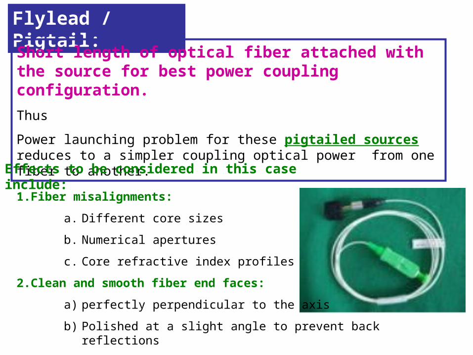
Flylead / Pigtail:
Short length of optical fiber attached with the source for best power coupling configuration.
Thus
Power launching problem for these pigtailed sources reduces to a simpler coupling optical power from one fiber to another.
Effects to be considered in this case include:
1.Fiber misalignments:
a. Different core sizes
b. Numerical apertures
c. Core refractive index profiles
2.Clean and smooth fiber end faces:
a) perfectly perpendicular to the axis
b) Polished at a slight angle to prevent back reflections
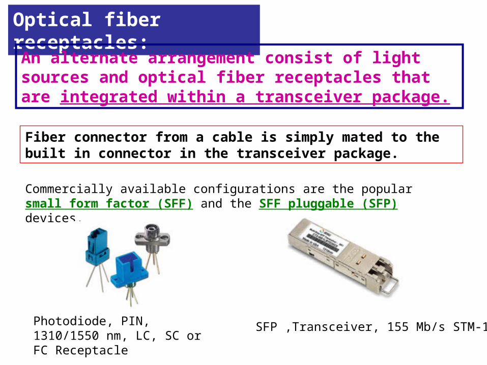
Optical fiber receptacles:
An alternate arrangement consist of light sources and optical fiber receptacles that are integrated within a transceiver package.
Fiber connector from a cable is simply mated to the built in connector in the transceiver package.
Commercially available configurations are the popular small form factor (SFF) and the SFF pluggable (SFP) devices.
Photodiode, PIN, 1310/1550 nm, LC, SC or FC Receptacle
SFP ,Transceiver, 155 Mb/s STM-1

Laser diodes with pigtails and Receptacle

Source to fiber power launchingOptical output of a luminescent source is usually measured by its radiance B at a given diode current.
Radiance: It is the optical power radiated into a unit solid angle per unit emitting surface area and is generally specified in terms of watts per square centimeter per steradian.
Radiance = Power / per unit solid angle x per unit emitting surface area
Solid angle is defined by the projected area of a surface patch onto a unit sphere of a point.
The angle that, seen from the center of a sphere, includes a given area on the surface of that sphere. The value of the solid angle is numerically equal to the size of that area divided by the square of the radius of the sphere
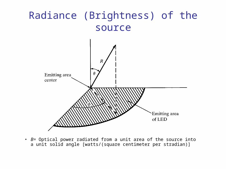
Radiance (Brightness) of the source
• B= Optical power radiated from a unit area of the source into a unit solid angle [watts/(square centimeter per stradian)]
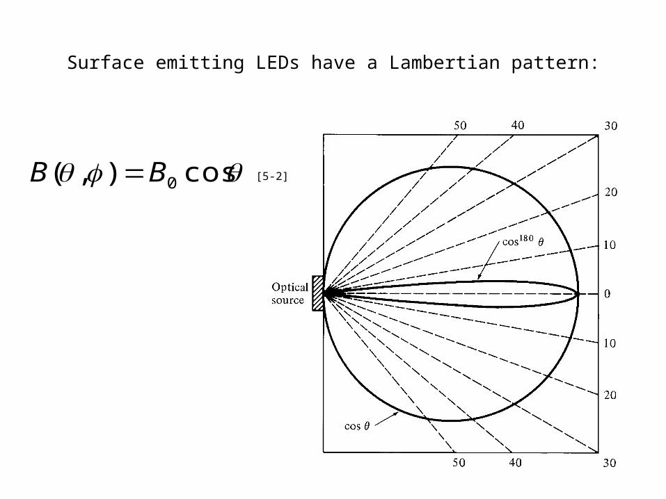
Surface emitting LEDs have a Lambertian pattern:
cos),( 0BB [5-2]
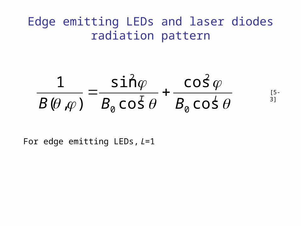
Edge emitting LEDs and laser diodes radiation pattern
LT BBB cos
cos
cos
sin
),(
1
0
2
0
2
For edge emitting LEDs, L=1
[5-3]

Power Coupled from source to the fiber
rdrdddB
dAdABP
s
r
s
A
sssF
m
f f
max0
0
2
0
2
00
sin),(
),([5-4]
source theof angleemission solid and area : and ssA
fiber of angle acceptance solid
and area : and ffA

Power coupled from LED to the Fiber
rdrdB
rdrdB
rdrddBP
s
r
s
r
s
r
s
s
s
22
00
0
2
0
max02
0
0
2
0 0
0
0
NA
sin
sincos2max0
210
2220
22stepLED, 2)NA( nBrBrP ss [5-5]

Power coupling from LED to step-index fiber
• Total optical power from LED:
sincos2
sin),(
2/
0
022
02
2
0
2/
0
BrdBrP
ddBAP
sss
ss
[5-6]
arP
r
a
arP
Pss
s
ss
if )NA(
if )NA(
2
2
2
stepLED, [5-7]

Power coupling from LED to graded-index fiber
• Power coupled from the LED to the graded indexed fiber is given as
• If the medium between source and fiber is different from the core material with refractive index n, the power coupled into the fiber will be reduced by the factor
a
rnP
rdrnrnBP
ss
r
oginLED
s
2
212
2
21
0
22
22,
2
1
1
nn
nnR

Power Launching Vs Wavelength
• Optical power only depends on the radiance and not on the wavelength of the mode. For a graded index fiber number of modes is related to the wavelength as
• So twice as many modes propagate for 900 nm as compared to 1300 nm but the radiated power per mode from a source is
• So twice as much power is launched per mode for 1300nm as compared to the 900nm
2
12
2
an
M
2os B
M
P

Equilibrium Numerical aperture
• For fibers with flylead attachments the connecting fiber should have the same NA. A certain amount of loss occurs at this junction which is almost 0.1 – 1dB. Exact loss depends on the connecting mechanism.
• Excess power loss occurs for few tens of meters of a multimode fiber as the launched modes come to the equilibrium.
• The excess power loss is due to the non propagating modes• The loss is more important for SLED.• Fiber coupled lasers are less prone to this effect as they have
very few non propagating modes.• The optical power in the fiber scales as

Equilibrium Numerical Aperture

Lensing Scheme for Coupling Improvement
Several Possible lensing schemes are:
1. Rounded end fiber
2. Nonimaging Microsphere (small glass sphere in contact with
both the fiber and source)
3. Imaging sphere ( a larger spherical lens used to image the
source on the core area of the fiber end)
4. Cylindrical lens (generally formed from a short section of fiber)
5. Spherical surfaced LED and spherical ended fiber
6. Taper ended fiber.

Examples of possible lensing scheme used to improve optical source to fiber coupling efficiency

Problem in using lens:
Lensing Scheme for Coupling Improvement
One problem is that the lens size is similar to the source and fiber core dimensions, which introduces fabrication and handling difficulties.
In the case of taper end fiber, the mechanical alignment must be carried out with great precision

Irfan khan
Non Imaging Microsphere
• Use for surface emitter is shown
• Assumptions: refractive indices shown in the fig. and emitting area is circular
• To collimate the output from the LED, the emitting surface should be located at the focal point of the lens which can be found as
• Where s and q are object and image distances as measured from the lens surface, n is the refractive index of the lens, n/ is the refractive index of the outside medium and r is the radius of curvature of the lens surface

Irfan khan
continued
The following sign conventions are used1. Light travels from left to right2. Object distances are measured as positive to the left of a vertex and
negative to the right3. Image distances are measured as positive to the right of a vertex and
negative to the left4. All convex surfaces encountered by the light have a positive radius of
curvature, and concave surfaces have a negative radius.
For these conventions, we can find the focal point for the right hand surface of the lens shown in the last fig. We set q = infinity, solve for s yields
s = f = 2RL
So the focal point is at point A. Magnification M of the emitting area is given as

Irfan khan
continued
Using eq. 5.4 one can show that, with the lens, the optical power PL that can be coupled into a full aperture angle 2θ is given by
For the fiber of radius a and numerical aperture NA, the maximum coupling efficiency max is given by
So when the radius of the emitting area is larger than the fiber radius, there’ll be no improvement in the coupling efficiency with the use of lens

Irfan khan
Laser diode to Fiber Coupling
• Edge emitting laser diodes have an emission pattern that nominally has FWHM of
• 30 – 50o in the plane perpendicular to the active area junction• 5 – 10o in the plane parallel to the junction
• As the angular output distribution of the laser is greater than the fiber acceptance angle and since the laser emitting area is much smaller than the fiber core, so that one can use
• spherical lenses• cylindrical lenses• Fiber taper
to improve the coupling efficiency between edge emitting laser diodes and optical fibers
• Same technique is used for vertical cavity surface emitting lasers (VCSELs).

Irfan khan
continued
• Mass produced connections of laser arrays to parallel multimode fiber has efficiencies of 35%
• Direct (lensless) coupling from a single VCSEL source to a multimode fiber results into efficiencies of upto 90%.
• The use of homogeneous glass microsphere lenses has been tested in series of several hundred laser diode assemblies.
• Spherical glass lens of refractive index 1.9 and diameters ranging between 50 and 60μm were epoxied to the ends of 50 μm core diameter graded index fibers having NA of 0.2. The measured FWHM values of the laser output beams were as follows
• b/w 3 and 9μm for the near field parallel to the junction• b/w 30 and 60o for the field perpendicular to the junction• b/w 15 and 55o for the field parallel to the junction Coupling efficiencies in these experiments ranged between 50 and
80%.
Irfan khan
Fiber-to-Fiber Joints
Interconnecting fibers in a fiber optic system is another very important factor. These interconnects should be low-loss. These interconnects occur at
• Optical source• Photodetector• Within the cable where two fibers are connected• Intermediate point in a link where two cables are connected
The connection can be
• Permanent bond: known as SPLICE
• Easily demountable connection: Known as CONNECTOR
Irfan khan
continued
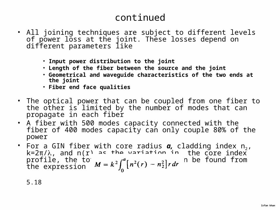
• All joining techniques are subject to different levels of power loss at the joint. These losses depend on different parameters like
• Input power distribution to the joint• Length of the fiber between the source and the joint• Geometrical and waveguide characteristics of the two ends at the joint• Fiber end face qualities
• The optical power that can be coupled from one fiber to the other is limited by the number of modes that can propagate in each fiber
• A fiber with 500 modes capacity connected with the fiber of 400 modes capacity can only couple 80% of the power
• For a GIN fiber with core radius a, cladding index n2, k=2π/, and n(r) as the variation in the core index profile, the total number of modes can be found from the expression
5.18

Irfan khan
continued
• Eq. 5.18 can be associated with the general local numerical aperture to yield
• As the different fibers can have different values of a, NA(0) and α, so M can be different for different fibers
• The fraction of energy that can be coupled is proportional to the common mode volume Mcomm. The fiber-to-fiber coupling efficiency F is given by
Where ME is the number of modes in the emitting fiber. The fiber-to-fiber coupling loss LF is given in terms of F as
LF = -10 log F

Irfan khan
Case a: All modes equally excited, joint with fiber of the same size having even slight mechanical misalignment can cause power loss
Case b: Propagating modes in the steady state have an equilibrium NA. Joining with an optical fiber of the same core size and same characteristics will face a NA of larger size in the receiving fiber and even a mechanical misalignment cannot cause the power loss.
case b is for longer fibers. Power loss will occur when in the receiving fiber, steady state will be achieved
Irfan khan
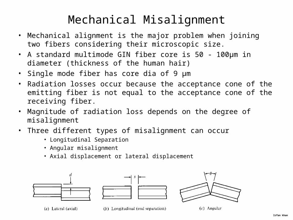
Mechanical Misalignment• Mechanical alignment is the major problem when joining two fibers
considering their microscopic size. • A standard multimode GIN fiber core is 50 - 100μm in diameter
(thickness of the human hair)• Single mode fiber has core dia of 9 μm • Radiation losses occur because the acceptance cone of the emitting
fiber is not equal to the acceptance cone of the receiving fiber.• Magnitude of radiation loss depends on the degree of misalignment• Three different types of misalignment can occur
• Longitudinal Separation• Angular misalignment• Axial displacement or lateral displacement

Irfan khan
Axial displacement
• Most common misalignment is the axial displacement.
• It causes the greatest power loss
Illustration:
• Axial offset reduces the overlap area of the two fiber-core end faces
• This in turn reduces the power coupled between two fibers.

Irfan khan
continued
• To illistrate the effect of misalignment, consider two identical step-index fibers of radii a.
• Suppose the axes are offset be a separation d• Assume there is a uniform mdal power distribution in the emitting
fiber.• NA is constant for the two fibers so coupled fiber will be proportional
to the common area Acomm of the two fiber cores
• Assignment: show that Acomm has expression
• For step index fiber, the coupling efficiency is simply the ratio of the common core area of the core end face area
Irfan khan
continued
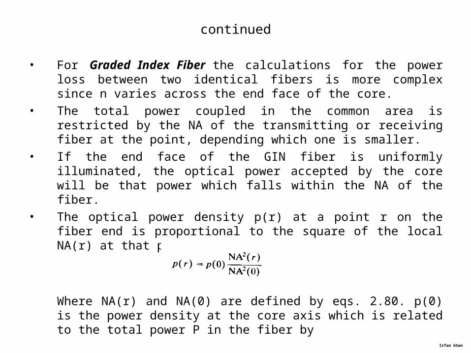
• For Graded Index Fiber the calculations for the power loss between two identical fibers is more complex since n varies across the end face of the core.
• The total power coupled in the common area is restricted by the NA of the transmitting or receiving fiber at the point, depending which one is smaller.
• If the end face of the GIN fiber is uniformly illuminated, the optical power accepted by the core will be that power which falls within the NA of the fiber.
• The optical power density p(r) at a point r on the fiber end is proportional to the square of the local NA(r) at that point
Where NA(r) and NA(0) are defined by eqs. 2.80. p(0) is the power density at the core axis which is related to the total power P in the fiber by
Irfan khan
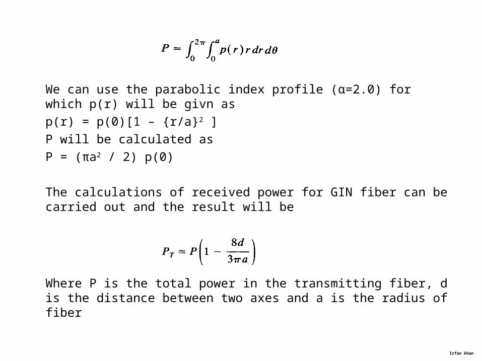
We can use the parabolic index profile (α=2.0) for which p(r) will be givn as
p(r) = p(0)[1 – {r/a}2 ]
P will be calculated as
P = (πa2 / 2) p(0)
The calculations of received power for GIN fiber can be carried out and the result will be
Where P is the total power in the transmitting fiber, d is the distance between two axes and a is the radius of fiber

Irfan khan
continued
The coupling loss for the offsets is given as
For Longitudinal misalignment:
For longitudinal misalignment of distance s, the coupling loss is given as
Where s is the misalignment and θc is the critical acceptance angle of the fiber

Irfan khan
Angular misalignment at the joint
When the axes of two fibers are angularly misaligned at the joint, the optical power that leaves the emitting fiber outside the acceptance angle of the receiving fiber will be lost. For two step index fibers with misalignment angle θ, the optical power loss at the joint will be
where

Irfan khan
Fiber Related Losses
Fiber losses are related to the• Core diameter• Core area ellipticity, numerical aperture• Refractive index profiles• Core-cladding concentricity
Fiber losses are significant for differences in core radii and NA
Different core radii: Loss is given as
Different NA: Power loss is given as

Irfan khan
Different core index profiles: Coupling loss will be given as

Irfan khan
Fiber End Face Preparation
• End face preparation is the first step before splicing or connecting the fibers through connectors.
• Fiber end must be • Flat• Perpendicular to the fiber axis• Smooth
• Techniques used are• Sawing• Grinding• Polishing
• Grinding and Polishing require a controlled environment like laboratory or factory

Irfan khan
continued
• Controlled fracture techniques are used to cleave the fiber
• Highly smooth and perpendicular end faces can be produced through this method
• Requires a careful control of the curvature and the tension• Improperly controlled tension can cause multiple fracture and can
leave a lip or hackled portion
Irfan khan
Fiber Splicing
Three different types of splicing can be done
• Fusion splicing• V-groove mechanical splicing• Elastic tube splice

Irfan khan
Self-Centering Effect
Influences on Fusion Process
The self-centering effect is the tendency of the fiber to form a homogeneous joint which is consequently free of misalignment as result of the surface tension of the molten glass during the fusion bonding process
Core Eccentricity
The process of aligning the fiber cores is of great importance in splicing. Fibers with high core eccentricity can cause , depending on the position of the relating cores, increased splice losses due to the core offset within the splice
Fiber End Face Quality
The end face quality of fibers to be fused directly influences the splice loss. Thus when cleaving fibers for splicing, the end face of the fiber has to be clean, unchipped, flat and perpendicular to the fiber axis

Irfan khan
Influences on Fusion Process
Fiber Preparation Quality
When preparing the fibers for splicing, it is necessary to ensure that no damage occurs to the fiber cladding
Any damage to the unprotected glass of the fiber can produce micro cracks causing the fiber to break during handling, splicing or storage
Dirt Particles or Coating Residues
Any contamination on the fiber cladding or in the v-grooves can lead to bad fiber positioning.
This can cause fiber offset (fiber axis misalignment) and can influence the fusion process extremely like bad cleave angles

Irfan khan
Influences on Fusion Process
Fiber Melting Characteristics
When fibers are brought together for splice some air gaps are present, called gas bubbles
Electric arc should not be too intense or weak.
When electric arc melts the fibers, the glass tends to collapse inwards, filling the gap
Electrode Condition
High quality splices require a reproducible and stable fusion arc.
Fusion arc is influenced by electrode condition.
Electrode cleaning or replacement is necessary from time to time.

Irfan khan
Fusion Splicing
• It is the thermal bonding of two prepared fiber ends
• The chemical changes during melting sometimes produce a weak splice
• Produce very low splice losses

Irfan khan
V-groove splicing
• The prepared fiber ends are first butt together in a V-shaped groove• They are bonded with an adhesive• The V-shaped channel is either grooved silicon, plastic ceramic or
metal substrate• Splice loss depends on the fiber size and eccentricity

Irfan khan
Elastic Tube splicing
• It automatically performs lateral, longitudinal and angular alignment• It splices multimode fiber with losses in the range as commercial
fusion splice• Less equipment and skills are needed• It consists of tube of an elastic material• Internal hole is of smaller diameter as compared to the fiber and is
tapered at two ends for easy insertion of the fiber• A wide range of fiber diameters can be spliced• The fibers to be spiced might not be of the same diameter, still its
axial alignment will be maximum
Irfan khan
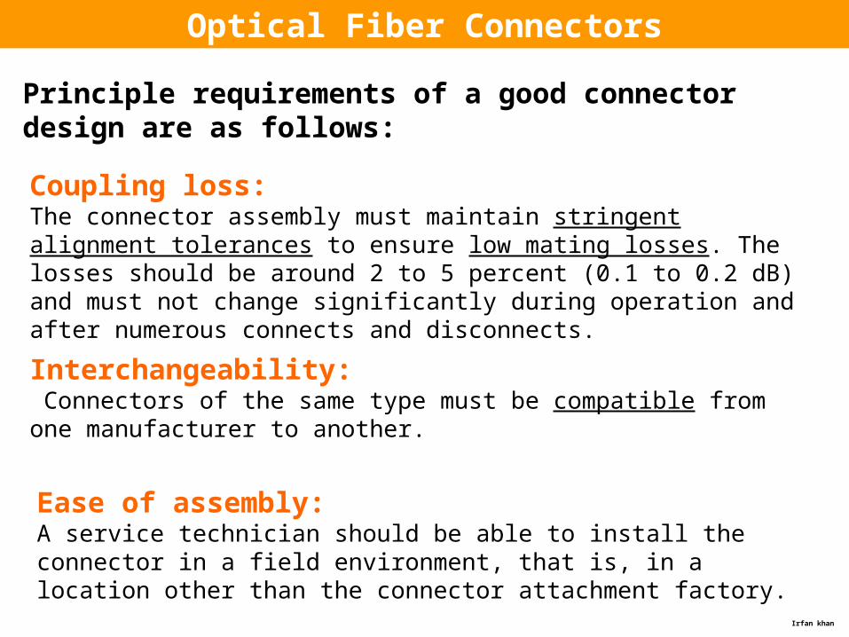
Optical Fiber Connectors
Principle requirements of a good connector design are as follows:
Coupling loss: The connector assembly must maintain stringent alignment tolerances to ensure low mating losses. The losses should be around 2 to 5 percent (0.1 to 0.2 dB) and must not change significantly during operation and after numerous connects and disconnects.
Interchangeability: Connectors of the same type must be compatible from one manufacturer to another.
Ease of assembly: A service technician should be able to install the connector in a field environment, that is, in a location other than the connector attachment factory.

Irfan khan
Low environmental sensitivity:Conditions such as temperature, dust, and moisture should have a small effect on connector loss variations.
Low cost and reliable construction:The connector must have a precision suitable to the application, but it must be reliable and its cost must not be a major factor in the system.
Ease of connection:Except for certain unique applications, one should be able to mate and disconnect the connector simply and by hand.

Irfan khan
Connector components
Connectors are available in designs that screw on, twist on, or snap in place. The twist-on and snap-on designs are the ones used most commonly.
The basic coupling mechanisms used belong to either butt-joint or the expanded-beam classes. The majority of connectors use a butt-joint coupling mechanism.
The key components are a long, thin stainless steel, glass,
ceramic, or plastic cylinder, known as a ferrule, and a precision sleeve into which the ferrule fits.
This sleeve is known variably as an alignment sleeve, an adapter, or a coupling receptacle.
The center of the ferrule has a hole that precisely matches the sizeof the fiber cladding diameter.
Butt-joint connector:
Irfan khan
Connector components
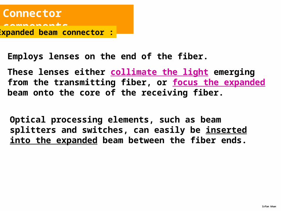
Expanded beam connector :
Employs lenses on the end of the fiber.
These lenses either collimate the light emerging from the transmitting fiber, or focus the expanded beam onto the core of the receiving fiber.
Optical processing elements, such as beam splitters and switches, can easily be inserted into the expanded beam between the fiber ends.

Irfan khan
Connector types
• Connector are available in designs that screw on, twist on, or snap into place
• Most commonly used are twist on, or snap on designs• These include single channel and multi channel assemblies• The basic coupling mechanism is either a Butt joint or an expanded
beam class• Butt joint connectors employ a metal, ceramic or a molded plastic
Ferrule for each fiber
Irfan khan
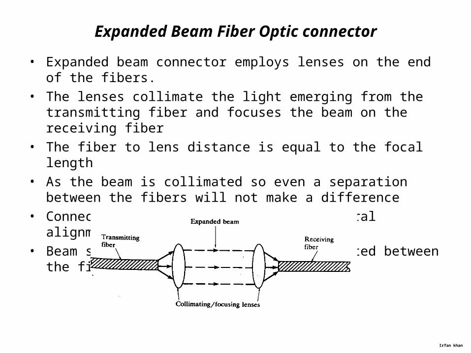
Expanded Beam Fiber Optic connector
• Expanded beam connector employs lenses on the end of the fibers.• The lenses collimate the light emerging from the transmitting fiber
and focuses the beam on the receiving fiber• The fiber to lens distance is equal to the focal length• As the beam is collimated so even a separation between the fibers
will not make a difference• Connector is less dependent on the lateral alignment• Beam splitters or switches can be inserted between the fibers

Irfan khan
Optical Connector Types
There are numerous connector styles and configurations.
The main ones are ST, SC, FC, LC, MU, MT-RJ, MPO, and variations on MPO.
ST is derived from the words straight tip, which refers to the ferrule configuration.
SC mean subscriber connector or square connector, although now the connectors are not known by those names.
A connector designed specifically for Fibre Channel applications was designated by the letters FC.
Since Lucent developed a specific connector type, they obviously nicknamed it the LC connector.
ST
SC
FC
LC
The letters MU were selected to indicate a miniature unit.MU

Irfan khan
The designation MT-RJ is an acronym for media termination—recommended jack.
Optical Connector Types
MT-RJ
The letters MPO were selected to indicate a multiple-fiber, push-on/pull-off connecting function.
MPO

Irfan khan
SC connectorST connector

Irfan khan
FC connector LC connector

Irfan khan
MU
MT-RJ
MPO
Irfan khan
Summary Coupling efficiencyFlylead / Pigtail
Optical fiber receptacles
Source to fiber power launching
Power coupling calculations
Lensing Scheme for Coupling Improvement
Fiber SplicingSplicing techniquesGood Splice RequirementsSplice PreparationInfluences on Fusion ProcessFusion Splicing Methods
Optical Fiber Connectors
Connector componentsOptical Connector Types
Coupling Losses
Intrinsic lossesExtrinsic losses
Irfan khan
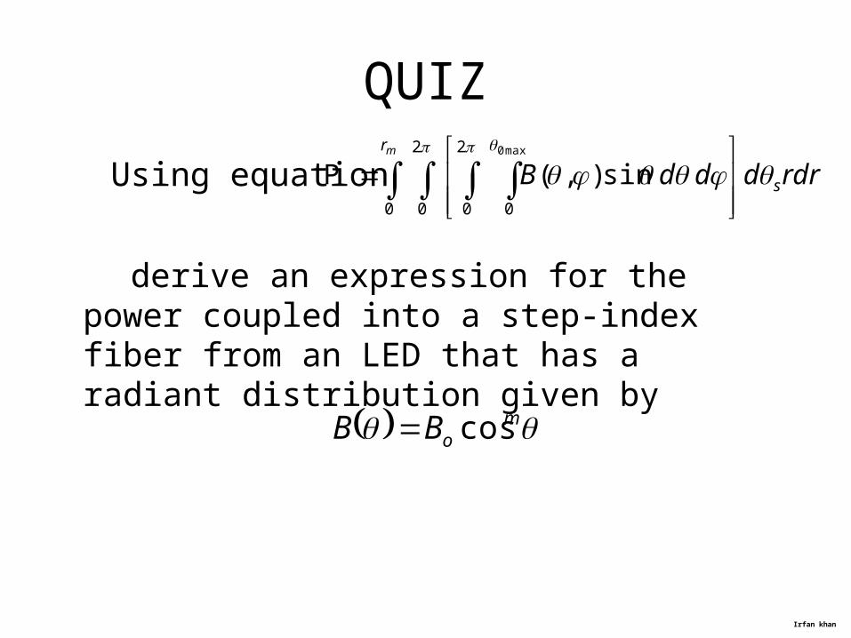
QUIZ
Using equation
derive an expression for the power coupled into a step-index fiber from an LED that has a radiant distribution given by
rdrdddB s
rm
max0
0
2
0
2
00
sin),( P
moBB cos
Top Related