


Languages
Pages
Legal

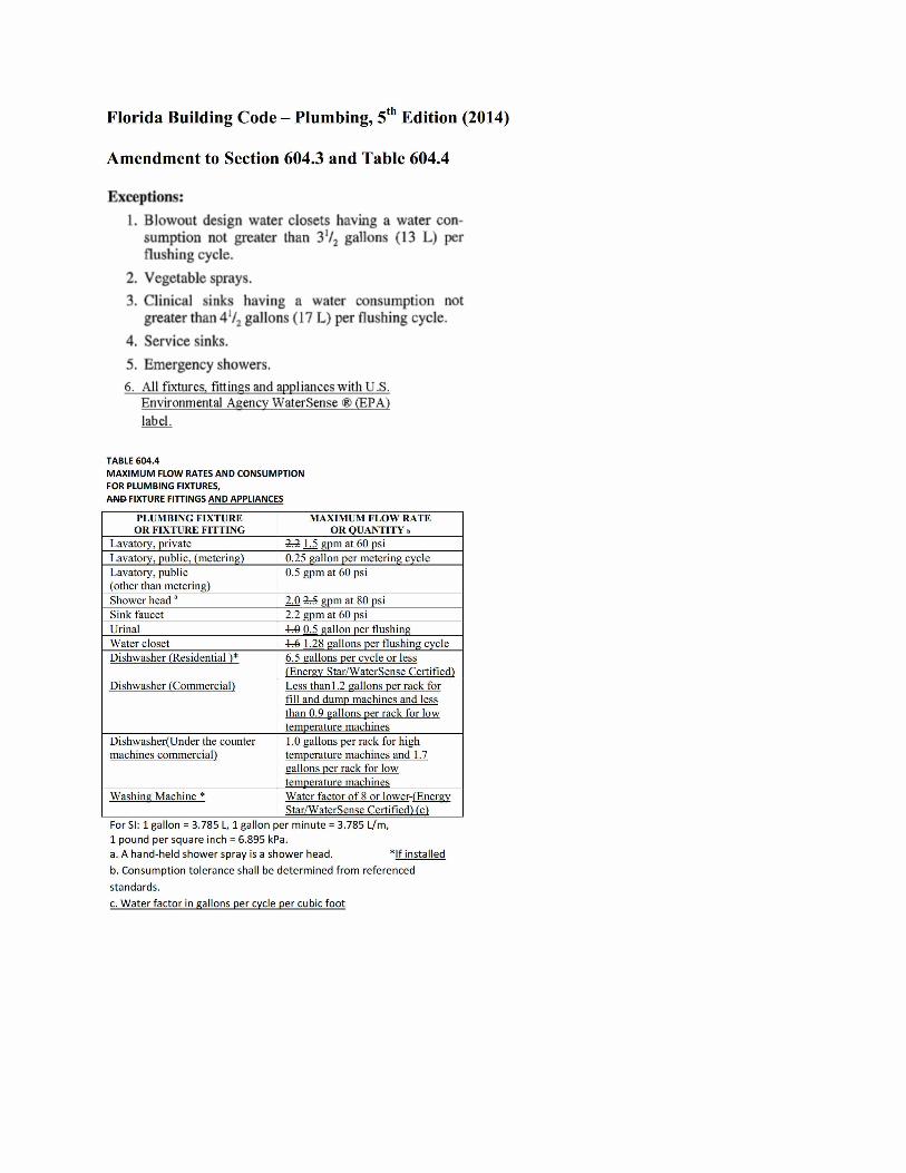
Florida Building Code - Plumbing, 5th Edition (2014)
Amendment to Section 604.3 and Table 604.4
Exceptions:
1. Blowout design water closets having a water con-sumption not greater than 3'/2 gallons (13 L) perflushing cycle.
2. Vegetable sprays.
3. Clinical sinks having a water consumption notgreater than 4'/2 gallons (17 L) per flushing cycle.
4. Service sinks.
5. Emergency showers.
6. All fixtures, fittings and appliances with U,S.
Environmental Agency WaterSense ® (EPA)
label.
TABLE 604.4
MAXIMUM FLOW RATES AND CONSUMPTION
FOR PLUMBING FIXTURES,
AND FIXTURE FITTINGS AND APPLIANCES
PLUMBING FIXTURE
OR FIXTURE FITTING
Lavatory, private
Lavatory, public, (metering)
Lavatory, public(other than metering)Shower head '
Sink faucet
Urinal
Water closet
Dishwasher (Residential )*
MAXIMUM FLOW RATE
OR QUANTITY .
1-4 13 gpm at 60 psi
0.25 gallon per metering cycle
0.5 gpm at 60 psi
2:Q 2-5 gpm at 80 psi
2.2 gpm at 60 psi
60 115 gallon per flushing
4=6 1.28 gallons per flushing cycle6.5 gallons per cycle or less
(Energy Star/WaterSense Certified}
Dishwasher (Commerciall Less than 1.2 gallons per rack for
fill and dump machines and less
than 0.9 gallons per rack for low
temperature niachines
Dishwasher(Under the counter 1.0 Hallons per rack for high
machines commerciall temperature machines and 1.7
gallons per rack for low
temperature machinesWashing Machine * Water factor of 8 or lower-(Energy
Star/WaterSense Certified) (c)
For SI: 1 gallon = 3.785 L, 1 gallon per minute = 3.785 L/m,
1 pound per square inch = 6.895 kPa.
a. A hand-held shower spray is a shower head. *If installed
b. Consumption tolerance shall be determined from referenced
standards.
c. Water factor in gallons per cycle per cubic foot
i 27* / S \\# 1
.
10 k./' 73''»C 1 0
Broward County
Board of Rules and AppealsOne N. University Drive, Suite 3500-8, Plantation, Florida 33324
TL 954.765.4500 4 FX 954.765.4504
http://www.broward.org/codeappeals
BROWARD COUNTY LOCAL AMENDMENT
Proposed Modification to the Florida Building Code
Per Section 553.73. Fla Stat
Name: Broward County, Board ofRules and Appeals, ATTN: J. DiPietro
Address: 1 North University Dr. Suite 350OB Plantation, FL 33324
E-mail: [email protected]
Phone: 954-765-4500
Fax: 954-765-4504
Code: 58 Edition (2014) FBC - Plumbing
Section #: 604 - Design of Building Water Distribution System, Table 604.4
Please see attachment.
THIS PROPOSED MODIFICATION SHALL BE EFFECTIVE JUNE 30, 2015.
Respond to the following questions:
1. How is the local amendment more stringent than the minimum standards described in the FBC?
This Amendment exceeds minimum standards by reducing plumbing fixture water flow rates
currently required by the Florida Building Code "Plumbing" thereby increasing water
conservation standards. This proposed amendment will adopt U.S. Environmental Protection
Agency (EPA) WaterSense Label as an Alternate for table 604.4.
2. Demonstrate or provide evidence or data that the geographical jurisdiction governed by the local
governing body exhibits a local need to strengthen the FBC beyond the needs or regional
variation addressed by the FBC.
Water conservation is an essential part of the Broward water supply plan and implementation of
high efficiency plumbing requirements is supported by the Broward County Board of County
Commissioners, the Broward League of Cities and the Broward Water Resources Task Force.
The Biscayne Aquifer is the primary source of drinking water for all of Broward County and
offers the lowest cost water supply for the region. However, concerns about future water
availability resulted in the permanent restrictions on withdrawals from this Aquifer while
saltwater intrusion limits withdrawals from two coastal well fields and threatens several others.
Efforts to conserve water are essential to preserving the capacity of existing water sources while
reducing the need to develop alternative water supplies which will impose a substantial cost to
rate payers.
3. Explain how the local need is addressed by the proposed local amendment.
This modification will help reduce the water demands on our Biscayne Aquifer while not creating
a health or inconvenience problem for the residents of this area.
4. Explain how the local amendment is no more stringent than necessary to address the local need.
The local need of water conservation is very serious as mandated by the Broward Commission.
The establishment of this amendment is only one of the means to help prevent a water shortage
situation.
5. Are the additional requirements discriminatory against materials, products, or construction
techniques of demonstrated capabilities?
Due to the advancement in technology by all Plumbing Fixture manufacturers and the need for
additional water conservation, this amendment would have little to no recognizable impact on
materials, products or construction developments.
6. Indicate whether or not additional requirements introduce a new subject not already addressed inthe FBC.
This amendment is modifying existing verbiage ofthe Florida Building Code "Plumbing",
therefore it does not address a new subject.
7. Include a fiscal impact statement which documents the costs and benefits of the proposed
amendment. Criteria for the fiscal impact statement shall include a, b, and c
a) Impact to local government, relative to enforcement.
b) Impact to property and building owners relative to cost of compliance.
c) Impact to industry relative to the cost of compliance
a) No impact.
b) This modification will reduce impactfees charged by Broward County.
0 No impact.
BROWARD BORA PUBLIC HEARING AND VOTE, 2015.
AMENDMENT EFFECTIVE DATE JUNE 30,2015.
G:\SHARED\FBC Amendments\2015\Plumbing 5thEdition\Section 603\604 StateForm.docx 5/26/2015
WATER SUPPLY AND DISTRIBUTION
6.2
SECTION 603
WATER SERVICE
603.1 Size of water service pipe. The water service pipeshall be sized to supply water to the structure in the quantitiesand at the pressures required in this code. The water servicepipe shall be not less than 3/4 inch (19.1 mm) in diameter.
603.2 Separation of water service and building sewer.Water service pipe and the building sewer shall be separatedby not less than 5 feet (1524 mm) of undisturbed or com-pacted earth.
Exceptions:
1. The required separation distance shall not applywhere the bottom of the water service pipe within 5feet (1524 mm) of the sewer is not less than 12inches (305 mm) above the top of the highest pointof the sewer and the pipe materials conform to Table702.3.
2. Water service pipe is permitted to be located in thesame trench with a building sewer, provided suchsewer is constructed of materials listed in Table
702.2.
3. The required separation distance shall not applywhere a water service pipe crosses a sewer pipe, pro-
vided the water service pipe is sleeved to a point notless than 5 feet (1524 mm) horizontally from thesewer pipe centerline on both sides of such crossingwith pipe materials listed in Table 605.3, 702.2 or702.3.
603.2.1 Water service near sources of pollution. Potablewater service pipes shall not be located in, under or abovecesspools, septic tanks, septic tank drainage fields or seep-age pits (see Section 605.1 for soil and groundwater condi-lions)
SECTION 604
DESIGN OF BUILDING WATER DISTRIBUTION
SYSTEM
604.1 General. The design of the water distribution systemshall conform to accepted engineering practice. Methods uti-lized to determine pipe sizes shall be approved.
604.2 System interconnection. At the points of interconnec-tion between the hot and cold water supply piping systemsand the individual fixtures, appliances or devices, provisionsshall be made to prevent flow between such piping systems.
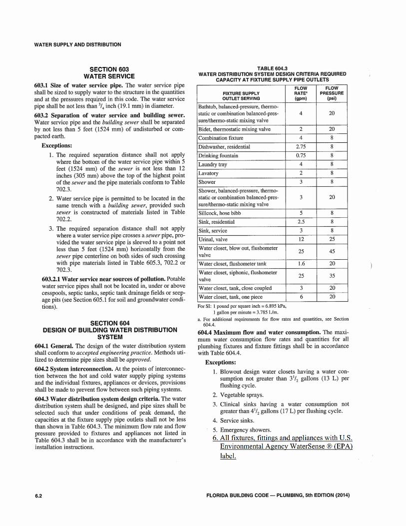
604.3 Water distribution system design criteria. The waterdistribution system shall be designed, and pipe sizes shall beselected such that under conditions of peak demand, thecapacities at the fixture supply pipe outlets shall not be lessthan shown in Table 604.3. The minimum flow rate and flow
pressure provided to fixtures and appliances not listed inTable 604.3 shall be in accordance with the manufacturer' sinstallation instructions.
TABLE 604.3
WATER DISTRIBUTION SYSTEM DESIGN CRITERIA REQUIRED
CAPACITY AT FIXTURE SUPPLY PIPE OUTLETS
FIXTURE SUPPLY
OUTLET SERVING
Bathtub, balanced-pressure, thermo-
static or combination balanced-pres-
sure/thermo-static mixing valve
Bidet, thermostatic mixing valve
Combination fixture
Dishwasher, residential
Drinking fountain
Laundry tray
Lavatory
Shower
Shower, balanced-pressure, thermo-
static or combination balanced-pres-
sure/thermo-static mixing valve
Sillcock, hose bibb
Sink, residential
Sink, service
Urinal, valve
Water closet, blow out, flushometer
valve
Water closet, flushometer tank
Water closet, siphonic, fit)shometervalve
Water closet, tank, close coupled
Water closet, tank, one piece
2
4
2.75
0.75
4
2
3
FLOW
RATES
(gpm)
4
3
25
1.6
25
5
2.5
3
12
3
6
FLOW
PRESSURE
(psi)
20
20
8
8
8
8
8
8
20
8
8
8
25
45
20
35
For SI: 1 pound per square inch = 6.895 kPa,
1 gallon per minute = 3.785 Um.
a. For additional requirements for flow rates and quantities, see Section604.4.
604.4 Maximum flow and water consumption. The maxi-mum water consumption flow rates and quantities for allplumbing fixtures and fixture fittings shall be in accordancewith Table 604.4.
Exceptions:
1. Blowout design water closets having a water con-sumption not greater than 31/2 gallons (13 L) perflushing cycle.
2. Vegetable sprays.
3. Clinical sinks having a water consumption notgreater than 41/2 gallons (17 L) per flushing cycle.
4. Service sinks.
5. Emergency showers,
6. All fixtures, fittings and appliances with U.S.
Environmental Agency WaterSense ® (EPA)
label.
FLORIDA BUILDING CODE - PLUMBING, 5th EDITION (2014)
20
20
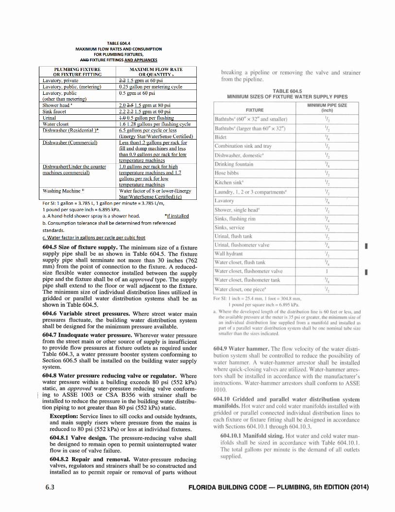
TABLE 604.4
MAXIMUM FLOW RATES AND CONSUMPTION
FOR PLUMBING FIXTURES,
ANG FIXTURE FITTINGS AND APPLIANCES
PLUMBING FIXTURE
OR FIXTURE FITTING
Lavatory, private
Lavatory, public, (metering)
Lavatory, public(other than metering)Shower head a
Sink faucet
Urinal
Water closet
Dishwasher (Residential )*
MAXIMUM FLOW RATE
OR QUANTITY .
2:213 gpm at 60 psi0.25 gallon per metering cycle
0.5 gpm at 60 psi
2,Q 2-5 13 gpm at 80 psi2,2 2-4 13 gpm at 60 psi
4,0 £13 gallon per flushing
4=61.28 gallons per flushing cycle6.5 gallons per cycle or less
(Energy Star/WaterSense Certified)
Dishwasher (Commerciall Less than 1.2 vallons per rack for
fill and dump machines and less
than 0.9 gallons per rack for low
temperature machines
Dishwasher(Under the counter 1.0 gallons per rack for high
machines commerciall temperature machines and 1.7
gallons per rack for low
temperature machines
Washing Machine * Water factor of 8 or lower-(Energy
Star/WaterSense Certified) (c)
For SI: 1 gallon = 3.785 L, 1 gallon per minute = 3.785 L./m,
1 pound per square inch = 6.895 kPa.
a. A hand-held showerspray is a shower head. *If installed
b. Consumption tolerance shall be determined from referenced
standards.
c. Water factor in gallons per cycle per cubic foot
604.5 Size of fixture supply. The minimum size of a fixturesupply pipe shall be as shown in Table 604.5. The fixturesupply pipe shall terminate not more than 30 inches (762mm) from the point of connection to the fixture, A reduced-size flexible water connector installed between the supplypipe and the fixture shall be of an approved type. The supplypipe shall extend to the floor or wall adjacent to the fixture.The minimum size of individual distribution lines utilized in
gridded or parallel water distribution systems shall be asshown in Table 604.5.
604.6 Variable street pressures. Where street water mainpressures fluctuate, the building water distribution systemshall be designed for the minimum pressure available.
604.7 Inadequate water pressure. Wherever water pressurefrom the street main or other source of supply is insufficientto provide flow pressures at fixture outlets as required underTable 604.3, a water pressure booster system conforming toSection 606.5 shall be installed on the building water supplysystem.
604.8 Water pressure reducing valve or regulator. Wherewater pressure within a building exceeds 80 psi (552 kPa)static, an approved water-pressure reducing valve conform-ing to ASSE 1003 or CSA B356 with strainer shall beinstalled to reduce the pressure in the building water distribu-tion piping to not greater than 80 psi (552 kPa) static.
6.3
Exception: Service lines to sill cocks and outside hydrants,and main supply risers where pressure from the mains isreduced to 80 psi (552 kPa) or less at individual fixtures.
604.8.1 Valve design. The pressure-reducing valve shallbe designed to remain open to permit uninterrupted waterflow in case of valve failure.
604.8.2 Repair and removal. Water-pressure reducingvalves, regulators and strainers shall be so constructed andinstalled as to permit repair or removal of parts without
breaking u pipeline c ir reti,£ 1iing the val\e and Mrainerfrm the pipeline.
TABLE 604.5
MINIMUM SIZES OF FIXTURE WATER SUPPLY PIPES
FIXTURE
Bathlubs' ((*)" x 32" and s.maller)
Bathrubs' (larger than 60" x 32")
Bidet
Combination sink and trai
1)ihwaher. domevic''
Drinking fountain
Hoxe hibbs
Kitchen ink'
1-aundry. 1.2 or.3 compartine,11¢
1..1 .itciry
Shower. ingle head'
Sinks. Iluhing rim
Sinks.service
Urinal. Ilush lank
Urilial. 111,410,neter valve
Wall hydrantWater closet, fluh tank
Water clo.et. Iluslic,meter valve
Water clowl. Iluhometer tank
Witter ch»,el, „tie piecey'
MINIMUM PIPE SIZE
(inch)
For .St I inch = 25.4 mm. I fc,c,1 = 3()4 .8 mm.
I piwild per *w.,te mch - 6 ><95 kl'a
a Where the desel„ped length *,1 thed:.tribull,in lii,e i. 6() teel „r le..ind
the av.tilable pre.ure .it the meter 3, 35 pv „r gre·,iter. lhe minimum 1/e „t.in Indiudial diuribution linc wpplied tr,itii .1 manih,hi and In.talled a,
part „1 ,* par,ille·l w .iler divrihution >.te'in h,ill be i,ne· miminal tihe vic.tiialler Ihan the .1/e indicated.
604.9 Water hammer. The flnw velocity 01 the water ditri-
hution >+Lent hall he Controlled ti, reduce the I,i,ihilit> 01water haminer. A water-haniner arre310, xhall be i,Nalled
uhere quick -clong Balies are utili/ed, Water-11,1,ii,iier arre1-tor hall he in31.illed in accordance with the mailul'acturer'*
intruction.. Water-hammer :irretors 11,111 conforni li) ANSI<
1010.
604.10 Gridded ;Ind parallel ,#:Iter distribution V Atemm:inifolds. 11£11 14 .,ter and cold u .iter iminiti,lil, in.talled with
gridded 4,1 parallel connected indisidual ditrihittion line4 toeach fi xture or fixture litting 111,111 he deiigned iii acc<,rilancewith Section5 604.10.1 througli 6()4.1().3.
604.10.1 Al:Inifuld sizing. Hot \#ater and cold water ni.„1ili,Id* hall be 51/ed M accord:itice with Table 6()4.10.1.
The lotal gal|(1114 per lilitilite iA the clematid 4,1 all (,utlebWpplied.
FLORIDA BUILDING CODE -- PLUMBING, 5th EDITION (2014)
l,
7*
1
1
1
Top Related