


Languages
Pages
Legal


electronic reprint
ISSN: 1600-5775
journals.iucr.org/s
Flexible sample cell for real-time GISAXS, GIWAXS and XRR:design and construction
M. Berlinghof, C. Bar, D. Haas, F. Bertram, S. Langner, A. Osvet, A.Chumakov, J. Will, T. Schindler, T. Zech, C. J. Brabec and T. Unruh
J. Synchrotron Rad. (2018). 25, 1664–1672
IUCr JournalsCRYSTALLOGRAPHY JOURNALS ONLINE
Copyright c© International Union of Crystallography
Author(s) of this paper may load this reprint on their own web site or institutional repository provided thatthis cover page is retained. Republication of this article or its storage in electronic databases other than asspecified above is not permitted without prior permission in writing from the IUCr.
For further information see http://journals.iucr.org/services/authorrights.html
J. Synchrotron Rad. (2018). 25, 1664–1672 M. Berlinghof et al. · Sample cell for GISAXS, GIWAXS and XRR
research papers
1664 https://doi.org/10.1107/S1600577518013218 J. Synchrotron Rad. (2018). 25, 1664–1672
Received 26 July 2018
Accepted 17 September 2018
Edited by I. Lindau, SLAC/Stanford University,
USA
Keywords: in situ; GIWAXS; GISAXS; XRR;
thin film.
Supporting information: this article has
supporting information at journals.iucr.org/s
Flexible sample cell for real-time GISAXS, GIWAXSand XRR: design and construction
M. Berlinghof,a C. Bar,a D. Haas,b F. Bertram,b S. Langner,c A. Osvet,c
A. Chumakov,f J. Will,a,e T. Schindler,a T. Zech,a C. J. Brabecc,d and T. Unruha,e*
aInstitute for Crystallography and Structural Physics (ICSP), Friedrich-Alexander-University Erlangen-Nurnberg (FAU),
Staudtstraße 3, 91058 Erlangen, Germany, bDESY Photon Science, Notkestraße 85, 22607 Hamburg, Germany,cInstitute Materials for Electronics and Energy Technology (i-MEET), Friedrich-Alexander-University Erlangen-Nurnberg
(FAU), Martensstraße 7, 91058 Erlangen, Germany, dBavarian Center for Applied Energy Research (ZAE Bayern),
Immerwahrstraße 2, 91058 Erlangen, Germany, eCenter for Nanoanalysis and Electron Microscopy (CENEM),
Friedrich-Alexander-University Erlangen-Nurnberg (FAU), Cauerstraße 6, 91058 Erlangen, Germany, and fThe European
Synchrotron Radiation Facility (ESRF), 71 Avenue des Martyrs, CS40220, 38043 Grenoble Cedex 9, France.
*Correspondence e-mail: [email protected]
Since the properties of functional materials are highly dependent on their
specific structure, and since the structural changes, for example during
crystallization, induced by coating and annealing processes are significant, the
study of structure and its formation is of interest for fundamental and applied
science. However, structure analysis is often limited to ex situ determination of
final states due to the lack of specialized sample cells that enable real-time
investigations. The lack of such cells is mainly due to their fairly complex design
and geometrical restrictions defined by the beamline setups. To overcome this
obstacle, an advanced sample cell has been designed and constructed; it
combines automated doctor blading, solvent vapor annealing and sample
hydration with real-time grazing-incidence wide- and small-angle scattering
(GIWAXS/GISAXS) and X-ray reflectivity (XRR). The sample cell has limited
spatial requirements and is therefore widely usable at beamlines and laboratory-
scale instruments. The cell is fully automatized and remains portable, including
the necessary electronics. In addition, the cell can be used by interested scientists
in cooperation with the Institute for Crystallography and Structural Physics and
is expandable with regard to optical secondary probes. Exemplary research
studies are presented, in the form of coating of P3HT:PC61PM thin films, solvent
vapor annealing of DRCN5T:PC71BM thin films, and hydration of supported
phospholipid multilayers, to demonstrate the capabilities of the in situ cell.
1. Introduction
In the recent decade, grazing-incidence X-ray scattering and
X-ray reflectivity have become crucial techniques for the
characterization of novel thin-film materials, like organic
photovoltaics (OPVs) (Proller et al., 2017; Sanyal et al., 2011;
Kassar et al., 2016; Wang et al., 2010; Guldal et al., 2017;
Muller-Buschbaum, 2014), molecular self-assembly at inter-
faces (Tang et al., 2005; Doshi et al., 2003; Steinruck et al., 2015;
Kirschner et al., 2017) and buried nanostructures and layers
(Ferrarese Lupi et al., 2017; Will et al., 2018; Jiang et al., 2011).
With the increasing flux and brilliance of synchrotron X-ray
sources and of state-of-the-art laboratory-scale instruments,
time-resolved in situ and operando studies became feasible. In
such studies further insight into structure formation processes
in thin films can be achieved upon drying and crystallization
(Proller et al., 2015; Kassar et al., 2016), annealing (Manley et
al., 2017; Gunkel et al., 2015), hydration (Kamata et al., 2014)
etc. To study those processes with grazing-incidence wide-
ISSN 1600-5775
# 2018 International Union of Crystallography
electronic reprint

angle X-ray scattering (GIWAXS), grazing-incidence small-
angle X-ray scattering (GISAXS) and X-ray reflectivity
(XRR) at beamlines, quite complex sample cells, which need
to be automatized, are required. Thus, some specialized cells
have been developed for in situ coating, e.g. doctor blading,
spray coating, roll-to-roll printing etc., by the authors of this
paper (Kassar et al., 2016; Guldal et al., 2016a) and by others
(Sanyal et al., 2011; Wang et al., 2010; Roth, 2016; Gu et al.,
2016; Liu et al., 2015). Many of these run under ambient
conditions. Other researchers have built sample cells specia-
lized for thermal annealing (Lilliu et al., 2012) or sample
hydration (Kucerka et al., 2005; Katsaras & Watson, 2000;
Wernecke, 2016). It is evident that there is a significant
scientific demand for suitable sample environments. There-
fore, we have designed and constructed a flexible setup which
allows for in situ and real-time studies of drying kinetics after
doctor blading of thin films, of solvent vapor annealing (SVA)
of thin films and of hydration of samples. The fully automated
and portable setup is designed for use at beamlines and
laboratory instruments. A similar approach was realized by
Proller et al. who constructed a sample cell for in situ studies of
slot-die coated samples using GIWAXS/GISAXS in combi-
nation with optical spectroscopy (Proller et al., 2017). In
contrast to this approach, our setup features a different but
very flexible coating technique (doctor blading) since doctor
blading is close to industrial roll-to-roll printing processes,
and still provides the necessary flexibility and reliability for
fundamental research (Krebs, 2009; Søndergaard et al., 2012;
Brabec & Durrant, 2008). In addition, our cell allows for very
homogeneous and stable temperature control, and is designed
to reach relative humidities close to 100% during hydration.
Moreover, this cell is available to the scientific community.
We openly encourage interested scientists to use our cell in
cooperation with the Institute for Crystallography and Struc-
tural Physics during beam times. In addition, the technical
drawings and specifications for duplication of the cell can be
provided. Some basic technical drawings are presented in xS1
of the supporting information.
After a technical description of the cell in x2, scientific
examples will be presented in x3 to demonstrate the capabil-
ities of the in situ cell. Each example focuses on different key
features and techniques usable with this cell. In the case of
OPVs, the power conversion efficiency (PCE) is strongly
dependent on the molecular structure of the bulk hetero-
junction thin films. Time-resolved GIWAXS studies provide
detailed insight into the structure formation and drying
kinetics needed for the design of efficient printed solar cells. In
this context, the first example is the time-resolved study of the
structure formation of P3HT:PC61BM after doctor blading
(x3.1). A P3HT:PC61BM solution was doctor bladed as it is one
of the most studied organic photoactive materials and is an
ideal reference sample. Another common tool used for opti-
mizing the structure of the photoactive layer with regard to
efficiency is to increase its crystallinity by post-processing the
device using SVA (Fuwen et al., 2018; Min et al., 2016, 2017;
Hu et al., 2014; Sun et al., 2014). In x3.2 the SVA-induced
crystallization of the small molecule photoactive material
DRCN5T:PC71BM is presented. Solid supported multilayers
of phospholipids like DMPC are commonly used as model
systems for membranes of biological cells used in life sciences
and pharmaceutical research (Teixeira et al., 2012; Peetla et al.,
2009). In order to match the conditions found in living
organisms these multilamellar systems need to be hydrated.
Structural changes of the DMPC multilayers during the
hydration process are presented in the last example of this
article (x3.3).
1.1. Methodology for sample annealing and hydration
In many cases, SVA is performed by pipetting the solvent
manually in a petri dish followed by incubation (Sun et al.,
2014; Min et al., 2016, 2017). It is evident that this kind of
annealing procedure is not suited for time-resolved repro-
ducible measurements. For this purpose the in situ cell can be
pumped constantly with solvent saturated gases. The flow of
the saturated gases is controlled by mass flow controllers,
which allow for a remarkably high reproducibility. Moreover,
they allow a precise adjustment of the solvent humidities from
0% up to a saturation of close to 100%. Thus, the annealing
speed and degree of annealing can be controlled accurately by
changing the vapor concentration inside the gas phase.
The hydration of thin films is often achieved by the
absorption of water from the gas phase with close to 100%
relative humidity (Kucerka et al., 2005; Nagle & Tristram-
Nagle, 2000). Placing the films in a closed cell next to a water
reservoir with a high surface-to-volume ratio is a common
approach (Wernecke, 2016; Katsaras & Watson, 2000; Jing et
al., 2009; Kucerka et al., 2005). In contrast to our in situ cell, a
constant stream of air saturated with water is pumped through
the cell. Analogous to SVA, this allows for precise control of
the degree and speed of hydration.
2. Technical description
The sample cell has been designed to meet spatial restrictions
of typical laboratory instruments and especially synchrotron
instruments, like the High Resolution Diffraction Beamline
P08 at PETRA III (DESY) (Seeck et al., 2012). Owing to its
compact design (see Fig. 1 and Table 1), the whole setup can
be installed easily on various instruments. Exemplary photo-
graphs of the in situ cell installed at several instruments are
presented in xS2 of the supporting information and a summary
of the specifications described in the paragraphs below is given
in Table 2.
The gas-tight sample cell is made of aluminium. The sample
stage inside the cell is made of copper, which enables a stable
and homogeneous temperature at the sample position. The
stage is covered by a flat 4 mm-thick glass-ceramics pane
(NEXTREMA 712-3N; Schott AG, Mainz, Germany), which
is perfectly suited as a base plate for coating experiments. The
cell features up to triple-pane windows (Nalophan; Kalle
GmbH, Wiesbaden, Germany) for the incoming and outgoing
X-ray beam to increase thermal isolation and prevent
condensation of vapors at elevated temperatures inside the
research papers
J. Synchrotron Rad. (2018). 25, 1664–1672 M. Berlinghof et al. � Sample cell for GISAXS, GIWAXS and XRR 1665electronic reprint

cell. The scattering background coming from the X-ray
windows is shown in Fig. 2 and is sufficiently low for most
sample systems. In addition the windows can be exchanged
with different kinds of materials like Kapton or mica and can
be reduced to single-pane windows. The size of the outgoing
X-ray windows also limits the maximal measurable scattering
angle 2�max = 34.5�. The size of the windows is a compromise
between the limited spatial freedom at many instruments and
the accessible angular range. This can be a limitation espe-
cially for measurements using tender X-ray energies. Thus, the
use of higher X-ray energies in the 20–30 keV range is often
recommended, which also reduces the extinction of the X-ray
beam by the atmosphere inside the cell and decreases the
probability for radiation damage (Richter & Kuzmenko,
2013).
The whole cell concept has been optimized to efficiently
perform real-time studies of thin-film formations after doctor
blading. A ZUA 2000 applicator (Zehntner GmbH, Sissach,
Switzerland) is used for blading, which allows a maximal
sample width of 60 mm. The cell mechanics limit the maximal
sample length to about 120 mm. The gap width of the appli-
cator can be adjusted between 0 mm and 3000 mm with a
precision of 10 mm. To optimize the homogeneity, quality and
thickness of the thin film it is necessary to adjust the blading
speed accordingly. The blading speed is one major parameter
for controlling the solution meniscus which is formed in
between the applicator and the substrate (Krebs, 2009).
Therefore, the applicator is driven by a stepper motor
(T5909X2508-B; Nanotec GmbH & Co. KG, Feldkirchen,
research papers
1666 M. Berlinghof et al. � Sample cell for GISAXS, GIWAXS and XRR J. Synchrotron Rad. (2018). 25, 1664–1672
Figure 1(a, b, c) Technical drawings of the automated in situ cell. Water-, solvent- and gas-hoses as well as optional optical probes are not depicted for clarity.(d) Photograph of the back side of the cell. Most connections (motor cables and heating, gas and water inlets) are removed for clarity.
Table 1Dimensions and weight of the in situ cell.
Dimensions of cables and hoses are not included in the tabulated values. Theinjection system and the controlled evaporator mixer can be removed, with thecorresponding dimensions being denoted as core. The width, length and heightof the cell are labeled as x, y and z, respectively (see Fig. 1).
Total Injection CoreFrontwindow
Backwindow
x (mm) 160 50 160y (mm) 491 187 214 40 97z (mm) 407 182 20 52
Mass (kg) 15
electronic reprint
Germany), which allows variable blading speeds from
0.25 mm s�1 up to 35 mm s�1.
The sample precursor solutions are applied by a motorized
syringe system (see Fig. 3) with typical sample volumes
between 50 ml and 200 ml and a maximum amount of 1 ml.
Since remote control is a necessity for operation at large-scale
facilities, both the blading and the sample injection are remote
controlled and scriptable, as is the rest of the sample cell (see
Fig. 4). For future upgrades, the cell is prepared to have a slot-
die applicator installed. This is even closer to industrial
printing than doctor blading.
Other important factors for the quality of the coated film is
the well defined temperature of the substrate, the atmosphere
inside the cell and the solvent used in the precursor solution.
For accurate temperature control the sample cell is connected
to an external water thermostat, with a Pt100 PTC-thermistor
placed inside the copper sample stage. To achieve a homo-
geneous temperature inside the cell, the sample stage, the
front, top and bottom walls and the edges of the cell are
heated by a temperated water flow. More details on the
temperature homogeneity and stability are given in xS3 of the
supporting information. Water containing additives limits the
achievable temperature range to between �20�C and 120�C.
In normal operation the sample stage and the rest of the
sample cell are thermally coupled, but can be decoupled if
needed.
In order to avoid radiation damage of the sample the whole
cell can be moved up to 40 mm perpendicular to the X-ray
beam by an external translation stage. The cell can also be
flushed with gases like helium or nitrogen which decrease the
risk of radiation damage on the sample and reduce scattering
of the gas phase in the in situ cell. For this purpose the cell is
equipped with a mass-flow controller for gases (EL-FLOW
Select, F-201CV-1K0-RGD-33-V; Bronkhorst High-Tech BV,
AK Ruurlo, The Netherlands) allowing the gas flow to be
adjusted in the range between 0 ln min�1 and 1 ln min�1. This
gas-mass-flow controller is part of a controlled evaporator
mixer (CEM) device (W-202A-330-K; Bronkhorst High-Tech
BV, AK Ruurlo, The Netherlands) which also includes a mass-
flow controller for liquids (MINI CORI-FLOW, M13-RGD-
33-O-S, Bronkhorst High-Tech BV, AK Ruurlo, The Nether-
lands) with a flow rate between 0 g h�1 and 1 g h�1. The liquid
is pumped into the in situ cell by pressurizing a filled washing
bottle with 1 bar excess pressure. This bottle also acts as a
reservoir for the liquid during the experiments. Both the gas
and the liquid flows are mixed in the CEM, which consists of a
research papers
J. Synchrotron Rad. (2018). 25, 1664–1672 M. Berlinghof et al. � Sample cell for GISAXS, GIWAXS and XRR 1667
Table 2Summary of the most important specifications of the in situ cell sorted bytheir occurrence in x2.
Applicator denotes the applicator of the doctor blade. Aliquot volume is thevolume which can be inserted on a substrate (for doctor blading) by theprecursor solution insertion system. The heating and cooling range of thesample is given for two heating mediums: pure water and water with additives.Translation denotes the range that the cell can be moved perpendicular to theX-ray beam by an external stage to minimize radiation damages. The last blockgives the specifications of the CEM. RT: room temperature.
Parameter Minimum Maximum
2� (�) 34.5
Sample width (mm) 60Sample length (mm) 120Applicator height (mm) 3000 � 10Blading speed (mm s�1) 0.25 35.0Aliquot volume (ml) 25 1000
Tpure water (�C) 3 97Twith additives (�C) �20 120
Translation (mm) 0 40
Gas flow (ln min�1) 0.0 1.0Solvent flow (g h�1) 0 100Tevaporator (�C) RT 200
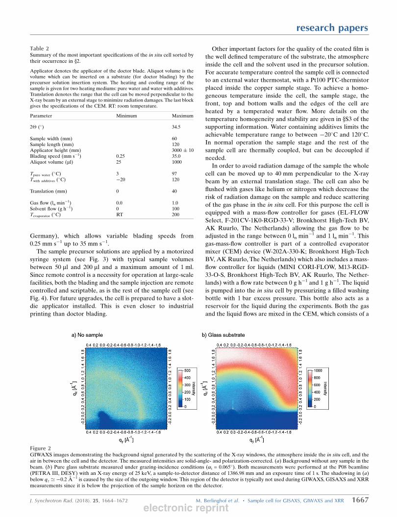
Figure 2GIWAXS images demonstrating the background signal generated by the scattering of the X-ray windows, the atmosphere inside the in situ cell, and theair in between the cell and the detector. The measured intensities are solid-angle- and polarization-corrected. (a) Background without any sample in thebeam. (b) Pure glass substrate measured under grazing-incidence conditions (�i = 0.065�). Both measurements were performed at the P08 beamline(PETRA III, DESY) with an X-ray energy of 25 keV, a sample-to-detector distance of 1386.98 mm and an exposure time of 1 s. The shadowing in (a)below qz ’�0.2 A�1 is caused by the size of the outgoing window. This region of the detector is typically not used during GIWAXS, GISAXS and XRRmeasurements since it is below the projection of the sample horizon on the detector.
electronic reprint

control valve and a thermal evaporator (see Fig. 4). The
thermal evaporator can be heated electrically up to 200�C,
which provides the necessary energy for the evaporation of
most liquids used in SVA or hydration experiments. The cell is
designed to withstand typical solvents used in SVA, with
chlorobenzene, chloroform, tetrahydrofuran, carbon disulfide
and water having already been used on a regular basis.
Examples of these applications are discussed in x3.2 and x3.3.
For many scientific studies additional complimentary
probes are desired. For example, optical techniques like white-
light reflectometry and photoluminescence spectroscopy are
often used to study (organic) thin films (Pistor et al., 2016;
Soltani et al., 2017; Guldal et al., 2016a; Bartelt et al., 2013).
Thus, the top cover of the cell can be exchanged easily with a
custom cover plate containing secondary probes. This concept
has been successfully tested in combination with previous
setups (Kassar et al., 2016; Guldal et al., 2016a,b).
3. Experimental use cases
In this section the capabilities of the in situ cell will be
demonstrated by three different experiments. X-ray scattering
experiments of the first (x3.1) and
second (x3.2) example were
performed at the P08 beamline at
PETRA III (DESY) (Seeck et al.,
2012). P08 is well suited for these
types of studies as it provides the
possibilities to characterize thin films
by XRR, GIWAXS and GISAXS
measurements. It is equipped with
a high-precision six-circle diffract-
ometer which allows for mounting of
sample environments with a total
weight of up to 15 kg. The GIWAXS
experiments at the P08 beamline were
performed using a photon energy
of 25 keV, a beam size of 0.1 mm �0.1 mm, a frame time of 0.1 s and an
XRD-1621 flat-panel detector (Perkin
Elmer Inc., Waltham, USA) with a sample-to-detector
distance of 1386.98 mm.
3.1. In situ doctor blading of P3HT:PC61BM
Doctor blading is a key method for studying thin-film
coatings for a large variety of applications. It is perfectly suited
for time-resolved studies of the drying kinetics of OPVs. As
discussed above, a key necessity for such time-resolved studies
on fast-drying thin films is the ability to vary the blading speed
over a wide range. This is one main feature discussed in this
section.
We chose a well known heterojunction OPV active layer
and used a 1.0 :1.0 weight ratio of poly(3-hexylthiophen-2,5-
diyl) (P3HT) (purity � 99%, regioregularity 96.6%; Merck
KGaA, Darmstadt, Germany) and [6,6]-phenyl-C61-butyric
acid methyl ester (PC61BM) (purity � 99%, Solenne BV,
Groningen, The Netherlands). 30 mg ml�1 of the
P3HT:PC61BM mixture were dissolved in chlorobenzene
(purity � 99.5%; Merck KGaA, Darmstadt, Germany) and a
50 ml aliquot was bladed with a blading speed vb of 7.5 mm s�1
on a {100} orientated silicon wafer (20 mm � 80 mm) with
a superficial native oxide layer (Siltronic AG, Munchen,
Germany). The temperature during the blading process and
the measurements was kept constant at 55�C. The measure-
ments were performed with an angle of incidence of 0.065�,
which is in between the critical angles of the substrate (�c,Si ’0.071�) and the P3HT:PC61BM layer (�c,layer ’ 0.057�) (Henke
et al., 1993). The data were reduced to qz-cuts using a custo-
mized version of the DPDAK software (Benecke et al., 2014)
without any further corrections.
During the film drying the diffraction patterns display the
rising intensity of the 100 Bragg peak at qz = 3.86 nm�1 which
corresponds to the formation of the lamellar stacking of P3HT
(see Fig. 5). Due to the low film crystallinity, higher orders of
the lamellar stacking were not resolved. P3HT also exhibits
the expected shrinking of the lamellar spacing starting
simultaneously with the crystallization of the 100 peak after
about 8 s (see Fig. 5c). As we have shown in our previous work
research papers
1668 M. Berlinghof et al. � Sample cell for GISAXS, GIWAXS and XRR J. Synchrotron Rad. (2018). 25, 1664–1672
Figure 3(a) Photograph of the inside of the in situ cell (with top cover removed) showing the doctor bladeabove a silicon substrate before coating. The sample precursor solution is inserted from the right-handside via a syringe with a long cannula. (b) Close-up of the sample precursor solution insertion system.
Figure 4Working principle of the automated sample cell. Arrows represent theflow of the different fluids. (CEM: controlled evaporator mixer, see x2).
electronic reprint
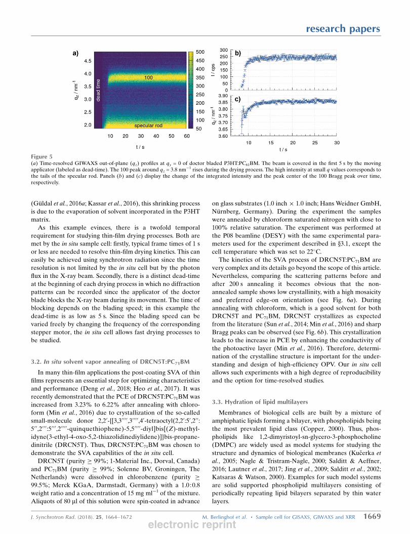
(Guldal et al., 2016a; Kassar et al., 2016), this shrinking process
is due to the evaporation of solvent incorporated in the P3HT
matrix.
As this example evinces, there is a twofold temporal
requirement for studying thin-film drying processes. Both are
met by the in situ sample cell: firstly, typical frame times of 1 s
or less are needed to resolve thin-film drying kinetics. This can
easily be achieved using synchrotron radiation since the time
resolution is not limited by the in situ cell but by the photon
flux in the X-ray beam. Secondly, there is a distinct dead-time
at the beginning of each drying process in which no diffraction
patterns can be recorded since the applicator of the doctor
blade blocks the X-ray beam during its movement. The time of
blocking depends on the blading speed; in this example the
dead-time is as low as 5 s. Since the blading speed can be
varied freely by changing the frequency of the corresponding
stepper motor, the in situ cell allows fast drying processes to
be studied.
3.2. In situ solvent vapor annealing of DRCN5T:PC71BM
In many thin-film applications the post-coating SVA of thin
films represents an essential step for optimizing characteristics
and performance (Deng et al., 2018; Heo et al., 2017). It was
recently demonstrated that the PCE of DRCN5T:PC71BM was
increased from 3.23% to 6.22% after annealing with chloro-
form (Min et al., 2016) due to crystallization of the so-called
small-molecule donor 2,20-{[3,30000,30000,40-tetraoctyl(2,20:50,200:500,2000:5000,200 00-quinquethiophene)-5,50000-diyl]bis[(Z)-methyl-
idyne(3-ethyl-4-oxo-5,2-thiazolidinediylidene)]}bis-propane-
dinitrile (DRCN5T). Thus, DRCN5T:PC71BM was chosen to
demonstrate the SVA capabilities of the in situ cell.
DRCN5T (purity � 99%; 1-Material Inc., Dorval, Canada)
and PC71BM (purity � 99%; Solenne BV, Groningen, The
Netherlands) were dissolved in chlorobenzene (purity �99.5%; Merck KGaA, Darmstadt, Germany) with a 1.0 :0.8
weight ratio and a concentration of 15 mg ml�1 of the mixture.
Aliquots of 80 ml of this solution were spin-coated in advance
on glass substrates (1.0 inch � 1.0 inch; Hans Weidner GmbH,
Nurnberg, Germany). During the experiment the samples
were annealed by chloroform saturated nitrogen with close to
100% relative saturation. The experiment was performed at
the P08 beamline (DESY) with the same experimental para-
meters used for the experiment described in x3.1, except the
cell temperature which was set to 22�C.
The kinetics of the SVA process of DRCN5T:PC71BM are
very complex and its details go beyond the scope of this article.
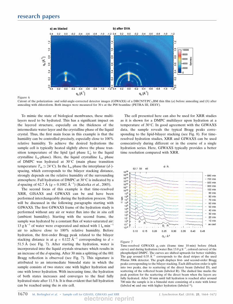
Nevertheless, comparing the scattering patterns before and
after 200 s annealing it becomes obvious that the non-
annealed sample shows low crystallinity, with a high mosaicity
and preferred edge-on orientation (see Fig. 6a). During
annealing with chloroform, which is a good solvent for both
DRCN5T and PC71BM, DRCN5T crystallizes as expected
from the literature (Sun et al., 2014; Min et al., 2016) and sharp
Bragg peaks can be observed (see Fig. 6b). This crystallization
leads to the increase in PCE by enhancing the conductivity of
the photoactive layer (Min et al., 2016). Therefore, determi-
nation of the crystalline structure is important for the under-
standing and design of high-efficiency OPV. Our in situ cell
allows such experiments with a high degree of reproducibility
and the option for time-resolved studies.
3.3. Hydration of lipid multilayers
Membranes of biological cells are built by a mixture of
amphiphatic lipids forming a bilayer, with phospholipids being
the most prevalent lipid class (Copper, 2000). Thus, phos-
pholipids like 1,2-dimyristoyl-sn-glycero-3-phosphocholine
(DMPC) are widely used as model systems for studying the
structure and dynamics of biological membranes (Kucerka et
al., 2005; Nagle & Tristram-Nagle, 2000; Salditt & Aeffner,
2016; Lautner et al., 2017; Jing et al., 2009; Salditt et al., 2002;
Katsaras & Watson, 2000). Examples for such model systems
are solid supported phospholipid multilayers consisting of
periodically repeating lipid bilayers separated by thin water
layers.
research papers
J. Synchrotron Rad. (2018). 25, 1664–1672 M. Berlinghof et al. � Sample cell for GISAXS, GIWAXS and XRR 1669
Figure 5(a) Time-resolved GIWAXS out-of-plane (qz) profiles at qy = 0 of doctor bladed P3HT:PC61BM. The beam is covered in the first 5 s by the movingapplicator (labeled as dead-time). The 100 peak around qz = 3.8 nm�1 rises during the drying process. The high intensity at small q values corresponds tothe tails of the specular rod. Panels (b) and (c) display the change of the integrated intensity and the peak center of the 100 Bragg peak over time,respectively.
electronic reprint
To mimic the state of biological membranes, these multi-
layers need to be hydrated. This has a significant impact on
the layered structure, especially on the thickness of the
intermediate water layer and the crystalline phase of the liquid
crystal. Thus, the first main focus in this example is that the
humidity can be controlled precisely, especially close to 100%
relative humidity. To achieve the desired hydrations the
sample cell is typically heated slightly above the phase tran-
sition temperature of the lipid (gel phase L0� to the liquid
crystalline L�-phase). Here, the liquid crystalline L� phase
of DMPC was hydrated at 30�C (main phase transition
temperature Tm ’ 24�C). In the L� phase the interplanar (d-)-
spacing, which corresponds to the bilayer stacking distance,
strongly depends on the relative humidity of the surrounding
atmosphere. Full hydration of DMPC at 30�C is indicated by a
d-spacing of 62.7 A (q = 0.1002 A�1) (Kucerka et al., 2005).
The second focus of this example is that time-resolved
XRR, GISAXS and GIWAXS can be and have been
performed interchangeably during the hydration process. This
will be discussed in the following paragraphs starting with
GIWAXS. The first GIWAXS frame of the hydration study is
performed without any air or water flux into the in situ cell
(ambient humidity). Starting with the second frame, the
sample was hydrated by a constant flux of water-saturated air:
13 g h�1 of water were evaporated and mixed with 1 ln min�1
air to achieve close to 100% relative humidity. Before
hydration, the first-order Bragg peak related to the bilayer
stacking distance is at q = 0.122 A�1 corresponding to d =
51.5 A (see Fig. 7). After starting the hydration, water is
incorporated into the liquid crystals structure which results in
an increase of the d-spacing. After 30 min a splitting of the 001
Bragg reflection is observed (see Fig. 7). This signature is
attributed to an intermediate bimodal state in which the
sample consists of two states: one with higher hydration and
one with lower hydration. With increasing time, the hydration
of both states increases and converges to the final fully
hydrated state after 11.5 h. It is thus evident that full hydration
can be reached using the in situ cell.
The cell presented here can also be used for XRR studies
as it is shown for a DMPC multilayer upon hydration at a
temperature of 30�C. In good agreement with the GIWAXS
data, the sample reveals the typical Bragg peaks corre-
sponding to the lipid-bilayer stacking (see Fig. 8). For time-
resolved hydration studies, XRR and GIWAXS can be used
consecutively during different or in the course of a single
hydration series. Here, GIWAXS typically provides a better
time resolution compared with XRR.
research papers
1670 M. Berlinghof et al. � Sample cell for GISAXS, GIWAXS and XRR J. Synchrotron Rad. (2018). 25, 1664–1672
Figure 7Time-resolved GIWAXS qz-cuts (frame time 10 min) before (blackcurve) and during hydration (water flux 13.0 g h�1, colored curves) of thephospholipid DMPC. The curves are shifted upwards for better visibility.The gap around 0.35 A�1 corresponds to the dead stripes of the usedPilatus 300k detector. The graph displays first- and second-order Braggpeaks corresponding to the bilayer stacking. Each diffraction order is splitinto two peaks, due to scattering of the direct beam (labeled D), andscattering of the reflected beam (labeled R). The dashed line marks thepeak position for the scattering of the direct beam when the layers arefully hydrated. After 30 min until full hydration is reached after around700 min the sample is in a bimodal state consisting of a state with lower(labeled �) and one with higher hydration (labeled *).
Figure 6Cutout of the polarization- and solid-angle-corrected detector images (GIWAXS) of a DRCN5T:PC71BM thin film (a) before annealing and (b) afterannealing with chloroform. Both images were measured for 30 s at the P08 beamline (PETRA III, DESY).
electronic reprint
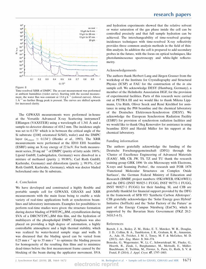
The GIWAXS measurements were performed in-house
at the Versatile Advanced X-ray Scattering instrumenT
ERlangen (VAXSTER) using a wavelength of 1.341 A and a
sample-to-detector distance of 418.2 mm. The incidence angle
was set to 0.170� which is in between the critical angle of the
Si substrate ({100} orientated Si/SiO2 wafer) and the DMPC
layer (�c,layer ’ 0.134�) (Henke et al., 1993). The XRR
measurements were performed at the ID10 EH1 beamline
(ESRF) using an X-ray energy of 22 keV. For both measure-
ment series, 20 mg ml�1 of DMPC (purity of fatty acids: 100%;
Lipoid GmbH, Ludwigshafen, Germany) were dissolved in a
mixture of methanol (purity � 99.98%; Carl Roth GmbH,
Karlsruhe, Germany) and chloroform (purity � 99.9%; Carl
Roth GmbH, Karlsruhe, Germany), which was doctor bladed
beforehand onto the Si substrate.
4. Conclusion
We have developed and constructed a highly flexible and
portable sample cell for GIWAXS, GISAXS and XRR
measurements with the main focus being to enable a wide
variety of real-time applications both at synchrotron beam-
lines and laboratory instruments. Examples for possibilities to
perform real-time studies were given: the structure formation
during doctor blading of P3HT:PC61BM, crystallization during
SVA of a DRCN5T:PC71BM thin film, and the hydration of
multilayers of the phospholipid DMPC. Emphasis was also
placed on providing a high degree of automation, a highly
controllable atmosphere and a high thermal stability, which
was realized by water-heated sample stage and walls. It
was discussed that the blading speed can be varied from
0.25 mm s�1 up to 35 mm s�1 to optimize the blading process
for homogeneity of the resulting thin films and to minimize
dead-times before the first measurement frame caused by the
blocking of the beam during the applicator movement. SVA
and hydration experiments showed that the relative solvent
or water saturation of the gas phase inside the cell can be
controlled precisely and that full sample hydration can be
achieved. The interchangeability of time-resolved grazing-
incidences techniques with time-resolved X-ray reflectivity
provides three common analysis methods in the field of thin-
film analysis. In addition the cell is prepared to add secondary
probes in the future, with the focus on optical techniques, like
photoluminescence spectroscopy and white-light reflecto-
metry.
Acknowledgements
The authors thank Herbert Lang and Jurgen Grasser from the
workshop of the Institute for Crystallography and Structural
Physics (ICSP) at FAU for the construction of the in situ
sample cell. We acknowledge DESY (Hamburg, Germany), a
member of the Helmholtz Association HGF, for the provision
of experimental facilities. Parts of this research were carried
out at PETRA III and we would like to thank Milena Lipp-
mann, Uta Ruth, Oliver Seeck and Rene Kirchhof for assis-
tance in using the P08 beamline and the chemical laboratory
of the Deutsches Elektronen-Synchrotron (DESY). We
acknowledge the European Synchrotron Radiation Facility
(ESRF) for provision of synchrotron radiation facilities and
we would like to thank Oleg Konovalov for assistance in using
beamline ID10 and Harald Muller for his support at the
chemical laboratory.
Funding information
The authors gratefully acknowledge the funding of the
Deutsche Forschungsgemeinschaft (DFG) through the
‘Cluster of Excellence Engineering of Advanced Materials
(EAM)’. MB, CB, JW, TS, TZ and TU thank the research
training group GRK 1896 ‘In situ Microscopy with Electrons,
X-rays and Scanning Probes’, the research unit FOR 1878
‘Functional Molecular Structures on Complex Oxide
Surfaces’, the German Federal Ministry of Education and
Research (BMBF, project numbers: 05K16WEB, 05K16WE1)
and the DFG (INST 90/825-1 FUGG, INST 90/751-1 FUGG,
INST 90/827-1 FUGG) for their funding. SL and CJB are
gratefully thankful for financial support provided by the DFG
in the framework of SFB 953 ‘Synthetic Carbon Allotropes’.
CJB gratefully acknowledges the ‘Solar Energy goes Hybrid’
Initiative (SolTech) and the ‘Solar Factory of the Future’ as
part of the Energy Campus Nurnberg (EnCN), which is
supported by the Bavarian State Government (FKZ 20.2-
3410.5-4-5).
References
Bartelt, J. A., Beiley, Z. M., Hoke, E. T., Mateker, W. R., Douglas,J. D., Collins, B. A., Tumbleston, J. R., Graham, K. R., Amassian,A., Ade, H., Frechet, J. M. J., Toney, M. F. & McGehee, M. D.(2013). Adv. Eng. Mater. 3, 364–374.
Benecke, G., Wagermaier, W., Li, C., Schwartzkopf, M., Flucke, G.,Hoerth, R., Zizak, I., Burghammer, M., Metwalli, E., Muller-Buschbaum, P., Trebbin, M., Forster, S., Paris, O., Roth, S. V. &Fratzl, P. (2014). J. Appl. Cryst. 47, 1797–1803.
research papers
J. Synchrotron Rad. (2018). 25, 1664–1672 M. Berlinghof et al. � Sample cell for GISAXS, GIWAXS and XRR 1671
Figure 8Time-resolved XRR of DMPC. The as-cast measurement was performedat ambient humidities (violet curve). Starting with the second measure-ment, the water flux was constant at 13.0 g h�1 (colored curves). Above1 A�1 no further Bragg peak is present. The curves are shifted upwardsfor increased clarity.
electronic reprint

Brabec, C. J. & Durrant, J. R. (2008). MRS Bull. 33, 670–675.Copper, G. M. (2000). The Cell: A Molecular Approach, 2nd ed.
American Society of Microbiology.Deng, W., Gao, K., Yan, J., Liang, Q., Xie, Y., He, Z., Wu, H., Peng, X.
& Cao, Y. (2018). Appl. Mater. Interfaces, 10, 8141–8147.Doshi, D. A., Gibaud, A., Goletto, V., Lu, M., Gerung, H., Ocko, B.,
Han, S. M. & Brinker, C. J. (2003). J. Am. Chem. Soc. 125, 11646–11655.
Ferrarese Lupi, F., Giammaria, T. J., Seguini, G., Laus, M., Dubcek, P.,Pivac, B., Bernstorff, S. & Perego, M. (2017). Appl. Mater.Interfaces, 9, 11054–11063.
Fuwen, Z., Chunru, W. & Xiaowei, Z. (2018). Adv. Eng. Mater. 109,1703147.
Gu, X., Reinspach, J., Worfolk, B. J., Diao, Y., Zhou, Y., Yan, H., Gu,K., Mannsfeld, S., Toney, M. F. & Bao, Z. (2016). Appl. Mater.Interfaces, 8, 1687–1694.
Guldal, N. S., Berlinghof, M., Kassar, T., Du, X., Jiao, X., Meyer, M.,Ameri, T., Osvet, A., Li, N., Destri, G. L., Fink, R. H., Ade, H.,Unruh, T. & Brabec, C. J. (2016b). J. Mater. Chem. A, 4, 16136–16147.
Guldal, N. S., Kassar, T., Berlinghof, M., Ameri, T., Osvet, A., Pacios,R., Li Destri, G., Unruh, T. & Brabec, C. J. (2016a). J. Mater. Chem.C. 4, 2178–2186.
Guldal, N. S., Kassar, T., Berlinghof, M., Unruh, T. & Brabec, C. J.(2017). J. Mater. Res. 32, 1855–1879.
Gunkel, I., Gu, X., Sun, Z., Schaible, E., Hexemer, A. & Russell, T. P.(2015). J. Polym. Sci. Part B Polym. Phys. 54, 331–338.
Henke, B., Gullikson, E. & Davis, J. (1993). At. Data Nucl. DataTables, 54, 181–342.
Heo, Y.-J., Jung, Y.-S., Hwang, K., Kim, J.-E., Yeo, J.-S., Lee, S., Jeon,Y.-J., Lee, D. & Kim, D.-Y. (2017). Appl. Mater. Interfaces, 9, 39519–39525.
Hu, S., Dyck, O., Chen, H., Hsiao, Y., Hu, B., Duscher, G., Dadmun,M. & Khomami, B. (2014). RSC Adv. 4, 27931–27938.
Jiang, Z., Lee, D. R., Narayanan, S., Wang, J. & Sinha, S. K. (2011).Phys. Rev. B, 84, 075440.
Jing, H. Y., Hong, D. H., Kwak, B. D., Choi, D. J., Shin, K., Yu, C.-J.,Kim, J. W., Noh, D. Y. & Seo, Y. S. (2009). Langmuir, 25, 4198–4202.
Kamata, Y., Parnell, A. J., Gutfreund, P., Skoda, M. W. A., Dennison,A. J. C., Barker, R., Mai, S., Howse, J. R., Ryan, A. J., Torikai, N.,Kawaguchi, M. & Jones, R. A. L. (2014). Macromolecules, 47, 8682–8690.
Kassar, T., Guldal, N. S., Berlinghof, M., Ameri, T., Kratzer, A.,Schroeder, B. C., Destri, G. L., Hirsch, A., Heeney, M., McCulloch,I., Brabec, C. J. & Unruh, T. (2016). Adv. Energy Mater. 6, 1502025.
Katsaras, J. & Watson, M. J. (2000). Rev. Sci. Instrum. 71, 1737–1739.
Kirschner, J., Will, J., Rejek, T. J., Portilla, L., Berlinghof, M.,Schweizer, P., Spiecker, E., Steinruck, H., Unruh, T. & Halik, M.(2017). Adv. Mater. Interfaces, 4, 1700230.
Krebs, F. C. (2009). Solar Energy Mater. Solar Cells, 93, 394–412.Kucerka, N., Liu, Y., Chu, N., Petrache, H. I., Tristram-Nagle, S. &
Nagle, J. F. (2005). Biophys. J. 88, 2626–2637.Lautner, L., Pluhackova, K., Barth, N. K., Seydel, T., Lohstroh, W.,
Bockmann, R. A. & Unruh, T. (2017). Chem. Phys. Lipids, 206, 28–42.
Lilliu, S., Agostinelli, T., Hampton, M., Pires, E., Nelson, J. &Macdonald, J. E. (2012). Energy Procedia, 31, 60–68.
Liu, F., Ferdous, S., Schaible, E., Hexemer, A., Church, M., Ding, X.,Wang, C. & Russell, T. P. (2015). Adv. Mater. 27, 886–891.
Manley, E. F., Strzalka, J., Fauvell, T. J., Jackson, N. E., Leonardi, M. J.,Eastham, N. D., Marks, T. J. & Chen, L. X. (2017). Adv. Mater. 29,1703933.
Min, J., Guldal, N. S., Guo, J., Fang, C., Jiao, X., Hu, H., Heumuller, T.,Ade, H. & Brabec, C. J. (2017). J. Mater. Chem. A, 5, 18101–18110.
Min, J., Jiao, X., Sgobba, V., Kan, B., Heumuller, T., Rechberger, S.,Spiecker, E., Guldi, D. M., Wan, X., Chen, Y., Ade, H. & Brabec,C. J. (2016). Nano Energy, 28, 241–249.
Muller-Buschbaum, P. (2014). Adv. Mater. 26, 7692–7709.Nagle, J. F. & Tristram-Nagle, S. (2000). Biochim. Biophys. Acta, 1469,
159–195.Peetla, C., Stine, A. & Labhasetwar, V. (2009). Mol. Pharm. 6, 1264–
1276.Pistor, P., Mainz, R., Heinemann, M. D., Unold, T. & Scheer, R.
(2016). Advanced Characterization Techniques for Thin Film SolarCells, Vol. 1, pp. 441–467. Wiley-VCH.
Proller, S., Liu, F., Zhu, C., Wang, C., Russell, T. P., Hexemer, A.,Muller-Buschbaum, P. & Herzig, E. M. (2015). Adv. Energy Mater.6, 1501580.
Proller, S., Moseguı Gonzalez, D., Zhu, C., Schaible, E., Wang, C.,Muller-Buschbaum, P., Hexemer, A. & Herzig, E. M. (2017). Rev.Sci. Instrum. 88, 066101.
Richter, A. G. & Kuzmenko, I. (2013). Langmuir, 29, 5167–5180.Roth, S. V. (2016). J. Phys. Condens. Matter, 28, 403003.Salditt, T. & Aeffner, S. (2016). Semin. Cell. Dev. Biol. 60, 65–77.Salditt, T., Li, C., Spaar, A. & Mennicke, U. (2002). Eur. Phys. J. E, 7,
105–116.Sanyal, M., Schmidt-Hansberg, B., Klein, M. F. G., Colsmann, A.,
Munuera, C., Vorobiev, A., Lemmer, U., Schabel, W., Dosch, H. &Barrena, E. (2011). Adv. Energy Mater. 1, 363–367.
Seeck, O. H., Deiter, C., Pflaum, K., Bertam, F., Beerlink, A., Franz,H., Horbach, J., Schulte-Schrepping, H., Murphy, B. M., Greve, M.& Magnussen, O. (2012). J. Synchrotron Rad. 19, 30–38.
Soltani, R., Katbab, A. A., Sytnyk, M., Yousefi Amin, A. A., Killilea,N., Berlinghof, M., Ahmadloo, F., Osvet, A., Unruh, T., Heiss, W. &Ameri, T. (2017). Sol. RRL, 1, 1700043.
Søndergaard, R., Hosel, M., Angmo, D., Larsen-Olsen, T. T. & Krebs,F. C. (2012). Mater. Today, 15, 36–49.
Steinruck, H. G., Will, J., Magerl, A. & Ocko, B. M. (2015). Langmuir,31, 11774–11780.
Sun, K., Xiao, Z., Hanssen, E., Klein, M. F. G., Dam, H. H., Pfaff, M.,Gerthsen, D., Wong, W. W. H. & Jones, D. J. (2014). J. Mater. Chem.A, 2, 9048–9054.
Tang, C., Tracz, A., Kruk, M., Zhang, R., Smilgies, D.-M.,Matyjaszewski, K. & Kowalewski, T. (2005). J. Am. Chem. Soc.127, 6918–6919.
Teixeira, V., Feio, M. J. & Bastos, M. (2012). Prog. Lipid Res. 51, 149–177.
Wang, T., Dunbar, A. D. F., Staniec, P. A., Pearson, A. J., Hopkinson,P. E., MacDonald, J. E., Lilliu, S., Pizzey, C., Terrill, N. J., Donald,A. M., Ryan, A. J., Jones, R. A. L. & Lidzey, D. G. (2010). SoftMatter, 6, 4128–4134.
Wernecke, J. (2016). PhD thesis, University of Lubeck, Germany.Will, J., Hou, Y., Scheiner, S., Pinkert, U., Hermes, I. M., Weber, S. A.,
Hirsch, A., Halik, M., Brabec, C. & Unruh, T. (2018). Appl. Mater.Interfaces, 10, 5511–5518.
research papers
1672 M. Berlinghof et al. � Sample cell for GISAXS, GIWAXS and XRR J. Synchrotron Rad. (2018). 25, 1664–1672
electronic reprint
Top Related