


Languages
Pages
Legal

Catalog
HA 35.41 ·
Supplement
September 2017
siemens.com/medium-voltage-switchgear
Fixed-Mounted Circuit-Breaker Switchgear Type NXPLUS C up to 24 kV, Gas-InsulatedMedium-Voltage Switchgear
R-H
A3
541
-18
5 t
if
2 Fixed-Mounted Circuit-Breaker Switchgear Type NXPLUS C up to 24 kV, Gas-Insulated · Siemens HA 35.41 · Supplement September 2017
Application PageTypical uses, ratings 3
Requirements Features, safety, technology 4 and 5
Technical data Electrical data 6
Room planning 7
Shipping data, classifi cation 8
Dimensions Front views, sections, fl oor openings, fi xing points 9 to 11
Product range Single-busbar panels 12
Design Basic panel design 13
Components Vacuum circuit-breaker 14 and 15
Three-position switch 16 and 17
HV HRC fuse assembly 18
Current transformers 19
Current sensors 20
Voltage sensors 21
Current and voltage transformers for air-insulated metering panel 22 and 23
Three-phase dry-type transformer for auxiliary transformer panel 24
Panel connection 25
Installation possibilities for cable connections and surge arresters, single-core PE and XLPE-insulated 26 and 27
Indicating and measuring equipment 28
Standards Standards, specifi cations, guidelines 29 to 31
Contents
Fixed-Mounted Circuit-Breaker Switchgear Type NXPLUS C up to 24 kV, Gas-Insulated
Medium-Voltage Switchgear
Catalog HA 35.41 ·Supplement September 2017
www.siemens.com/medium-voltage-switchgearwww.siemens.com/NXPLUSC-SBBwww.siemens.com/NXPLUSC-DBB
Circuit-breaker panel 450 mm
3Fixed-Mounted Circuit-Breaker Switchgear Type NXPLUS C up to 24 kV, Gas-Insulated · Siemens HA 35.41 · Supplement September 2017
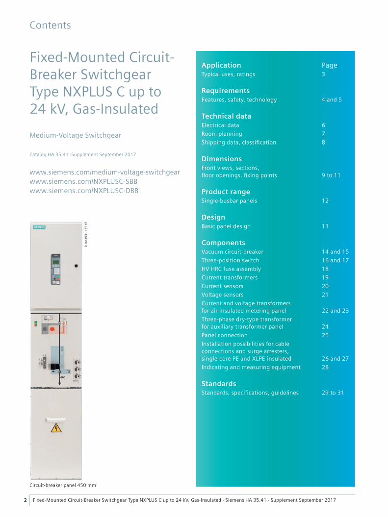
Fixed-mounted circuit-breaker switchgear NXPLUS C is a factory-assembled, type-tested, metal-enclosed, SF6-insulated switchgear with metallic partitions 4) for single-busbar and double-busbar applications for indoor installation.
It is used in transformer and switching substations, e.g., in:
• Power supply companies• Power stations• Cement industry• Automotive industry• Iron and steel works• Rolling mills• Mining industry• Textile, paper and food industries• Chemical industry• Petroleum industry• Pipeline installations• Offshore installations• Electrochemical plants• Petrochemical plants• Shipbuilding industry• Diesel power plants• Emergency power supply installations• Lignite open-cast mines• Traction power supply systems.
1) 32 kV / 60 kV according to some national requirements
2) 42 kV / 75 kV according to some national requirements
3) 450 mm: LS 630 A, 800 A600 mm: LS 630 A, 1000 A, 1250 A, TS, LK, ME, VS, RK, TR900 mm: LS 2000 A, 2500 A TS, LK, 2000 A, 2500 A EB aME
4) Corresponds to “metal-clad” according to former standard IEC 60298
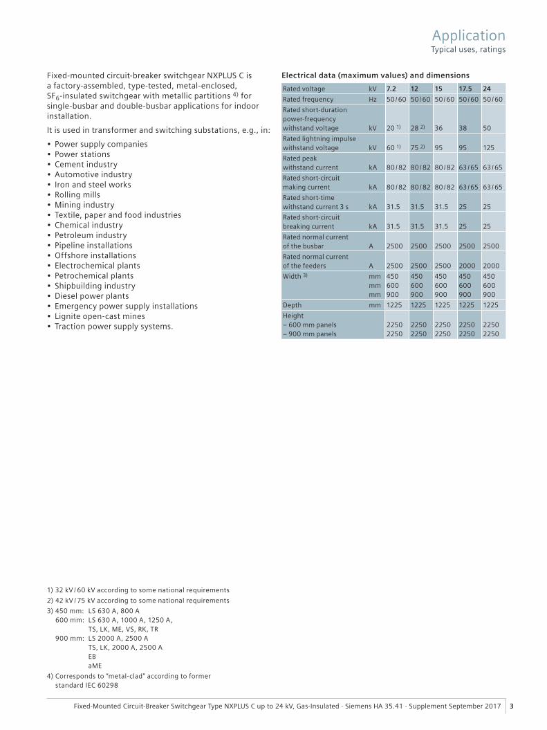
Electrical data (maximum values) and dimensions
Rated voltage kV 7.2 12 15 17.5 24
Rated frequency Hz 50 / 60 50 / 60 50 / 60 50 / 60 50 / 60
Rated short-duration power-frequency withstand voltage kV 20 1) 28 2) 36 38 50
Rated lightning impulse withstand voltage kV 60 1) 75 2) 95 95 125
Rated peak withstand current kA 80 / 82 80 / 82 80 / 82 63 / 65 63 / 65
Rated short-circuitmaking current kA 80 / 82 80 / 82 80 / 82 63 / 65 63 / 65
Rated short-timewithstand current 3 s kA 31.5 31.5 31.5 25 25
Rated short-circuitbreaking current kA 31.5 31.5 31.5 25 25
Rated normal currentof the busbar A 2500 2500 2500 2500 2500
Rated normal currentof the feeders A 2500 2500 2500 2000 2000
Width 3) mm mm mm
450600 900
450600 900
450600 900
450600 900
450600 900
Depth mm 1225 1225 1225 1225 1225
Height – 600 mm panels– 900 mm panels
22502250
22502250
22502250
22502250
22502250
Application Typical uses, ratings
4 Fixed-Mounted Circuit-Breaker Switchgear Type NXPLUS C up to 24 kV, Gas-Insulated · Siemens HA 35.41 · Supplement September 2017
Environmental independenceHermetically tight, welded switchgear vessels made of stain-less steel as well as single-pole solid insulation make the parts of the primary circuit under high voltage of NXPLUS C switchgear• Insensitive to certain aggressive ambient conditions, such as:
– Saline air – Air humidity – Dust – Condensation
• Tight to ingress of foreign objects, such as: – Dust – Pollution – Small animals – Humidity
• Independent of the site altitude.This high degree of environmental independence cannot be achieved for the air-insulated metering panel due to the partial air insulation (block-type current transformers, block-type voltage transformers with connecting bars).
Compact designThanks to the use of SF6 insulation, compact dimensions are possible. Thus:• Existing switchgear rooms and substation rooms can be
used effectively• New constructions cost little• Costly city-area space is saved.
Maintenance-free designSwitchgear vessels designed as sealed pressure systems, maintenance-free switching devices and enclosed cable plugs ensure:• Maximum supply reliability• Personnel safety• Sealed-for-life design according to IEC 62271-200
(sealed pressure system)• Installation, operation, extension and replacement
without SF6 gas work• Reduced operating costs• Cost-efficient investment• No maintenance cycles.
InnovationThe use of digital secondary systems and combined protec-tion and control devices ensures:• Clear integration in process control systems• Flexible and highly simplified adaptation to new system
conditions and thus to cost-efficient operation.
Service lifeUnder normal operating conditions, the expected service life of gas-insulated switchgear NXPLUS C is at least 35 years, probably 40 to 50 years, taking the tightness of the hermeti-cally welded switchgear vessel into account. The service life is limited by the maximum number of operating cycles of the switching devices installed:• For circuit-breakers according to the endurance class defined
in IEC 62271-100• For three-position disconnectors and earthing
switches according to the endurance class defined in IEC 62271-102
• For three-position switch disconnectors and earthing switches according to the endurance class defined in IEC 62271-103.
Personal safety• Safe-to-touch and hermetically sealed primary enclosure• Cable terminations, busbars and voltage transformers are
surrounded by earthed layers• All high-voltage parts including the cable terminations,
busbars and voltage transformers are metal-enclosed• Capacitive voltage detecting system to verify safe
isolation from supply• Operating mechanisms and auxiliary switches safely
accessible outside the primary enclosure (switchgear vessel)
• Due to the system design, operation is only possible with closed switchgear enclosure
• Standard degree of protection IP 65 for all high-voltage parts of the primary circuit, IP 3XD for the switchgear enclosure according to IEC 60529 and VDE 0470-1
• High resistance to internal arcs by logical mechanical interlocks and tested switchgear enclosure
• Panels tested for resistance to internal faults up to 31.5 kA
• Logical mechanical interlocks prevent maloperation• Make-proof earthing by means of the vacuum circuit-
breaker.
Security of operation• Hermetically sealed primary enclosure independent of
environmental effects (pollution, humidity and small animals)
• Maintenance-free in an indoor environment (IEC 62271-1 and VDE 0671-1)
• Operating mechanisms of switching devices accessible outside the primary enclosure (switchgear vessel)
• Metal-coated and plug-in inductive voltage transformers mounted outside the SF6 switchgear vessel
• Current transformers as ring-core current transformers mounted outside the SF6 switchgear vessel
• Complete switchgear interlocking system with logical me-chanical interlocks
• Welded switchgear vessels, sealed for life• Minimum fire load• Type and routine-tested• Standardized and manufactured using numerically
controlled machines• Quality assurance in accordance with DIN EN ISO 9001• More than 500,000 switchgear panels of Siemens
in operation worldwide for many years.
Reliability• Type and routine-tested• Standardized and manufactured using numerically
controlled machines• Quality assurance in accordance with DIN EN ISO 9001• More than 500,000 switchgear panels of Siemens
in operation worldwide for many years.
Requirements Features Safety
5Fixed-Mounted Circuit-Breaker Switchgear Type NXPLUS C up to 24 kV, Gas-Insulated · Siemens HA 35.41 · Supplement September 2017
General• 3-pole enclosure of the primary part consisting of a
switchgear vessel made of stainless steel• Insulating gas SF6 (fluorinated greenhouse gas)• Three-position switch as busbar disconnector and
feeder earthing switch• Make-proof earthing by means of the vacuum
circuit-breaker• Compact dimensions due to SF6 insulation• Hermetically tight, welded switchgear vessel made of
stainless steel• 1-pole, solid-insulated, screened busbars, plug-in type• Cable connection with outside-cone plug-in system,
or for connection of solid-insulated bars• Wall-standing or free-standing arrangement• Cable connection access from front• Low-voltage door hinge on the left and or the right• Installation and extension of existing switchgear at both
ends without gas work and without modification of existing panels
• Option: Flexible pressure relief duct systems.
Interlocks• According to IEC 62271-200 and VDE 0671-200• Logical mechanical interlocks prevent maloperation• Interlocking of three-position disconnector
– if the “DISCONNECTING” function is in CLOSED position, the “READY-TO-EARTH” function cannot be selected
– if the “READY-TO-EARTH” function is in CLOSED position, the “DISCONNECTING” function cannot be selected
• Interlocking of three-position switch-disconnector – if the “LOAD BREAKING” function is in CLOSED position, the “EARTHING” function cannot be selected
– if the “EARTHING” function is in CLOSED position, the “LOAD BREAKING” function cannot be selected
• Three-position disconnector can only be operated with circuit-breaker in OPEN position
• Circuit-breaker can only be operated with three-position switch in end position and operating lever removed
• “Feeder earthed” locking device• Locking device for three-position switch
The following interlocks can be fulfilled by placing the padlock accordingly:
– Padlock on the left: Three-position switch “DISCONNECTING” function cannot be operated, three-position switch “READY-TO-EARTH” function can be operated
– Padlock in the center: Control gate blocked, no switching operations possible
– Padlock on the right: Three-position switch “DISCONNECTING” function can be operated, three-position switch “READY-TO-EARTH” function cannot be operated
• Auxiliary transformer panel (with switch-disconnector) not interlocked due to its own switching capacity
• Fuse cover (access to HV HRC fuses) in auxiliary trans-former panel always interlocked against three-position switch-disconnector
• Fuse compartment can only be closed if the fuse box is completely closed
• De-earthing lockout when the fuse cover is removed• Option: Cable compartment cover interlocked against the
three-position switch (circuit-breaker panel)
• Option: Auxiliary transformer compartment interlocked against three-position switch-disconnector (auxiliary transformer panel)
• Option: Closing lockout for mechanical CLOSING of circuit-breaker
• Option: Closing lockout for three-position disconnector “DISCONNECTING” function when the cable compart-ment cover / instrument transformer compartment cover is removed (circuit-breaker panel, air-insulated metering panel)
• Option: Electromagnetic interlocks (-Y1, -Y5, -Y8E, -Y16, -Y32)
• Option: Mechanical pushbuttons of the circuit-breaker can be padlocked
• Option: “Feeder” locking device.
Modular design• Panel replacement possible without SF6 gas work• Low-voltage compartment removable, plug-in bus wires.
Instrument transformers• Current transformers not subjected to dielectric stress• Easy replacement of current transformers designed as
ring-core transformers• Metal-coated, plug-in and disconnectable voltage trans-
formers• Block-type current and block-type voltage transformers
in the air-insulated metering panel, also possible as customer supply (block-type current transformers are sub-ject to dielectric stress).
Sensors• Current sensor as inductive current transformer
in combination with precision shunt (voltage signal)• Voltage sensor as resistor divider• In combination with secondary devices such as
– SICAM FCM – 7SJ81.
Auxiliary transformer• Three-phase dry-type transformer• Power 40 kVA• Connection symbol Dyn1 or Dyn5• According to Ecodesign Directive
No. 548 /2014 of the EU.
Vacuum circuit-breaker• Maintenance-free under normal ambient conditions
according to IEC 62271-1 and VDE 0671-1• No relubrication or readjustment• Up to 10,000 operating cycles• Vacuum-tight for life.
Secondary systems• Customary protection, measuring and control equipment• Option: Numerical multifunction protection relay with
integrated protection, control, communication, operating and monitoring functions
• Can be integrated in process control systems.
Standards (see page 29)
Requirements Technology
6 Fixed-Mounted Circuit-Breaker Switchgear Type NXPLUS C up to 24 kV, Gas-Insulated · Siemens HA 35.41 · Supplement September 2017
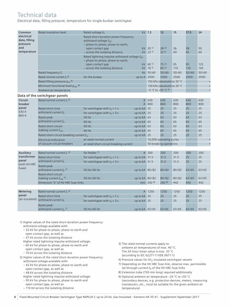
Common electrical data, fi lling pressure and temperature
Rated insulation level Rated voltage Ur kV 7.2 12 15 17.5 24
Rated short-duration power-frequency withstand voltage Ud:– phase-to-phase, phase-to-earth,
open contact gap kV– across the isolating distance kV
20 1)
23 1)
28 2)
32 2)
3640
3845
5060
Rated lightning impulse withstand voltage Up:– phase-to-phase, phase-to-earth,
open contact gap kV– across the isolating distance kV
60 1)
70 1)
75 2)
85 2)
95110
95110
125145
Rated frequency fr Hz 50 / 60 50 / 60 50 / 60 50 / 60 50 / 60
Rated normal current Ir 3) for the busbar up to A 2500 2500 2500 2500 2500
Rated fi lling pressure pre 4)
Minimum functional level pme 4)
Ambient air temperature
Data of the switchgear panelsCircuit-breaker panel 630 A800 A
Rated normal current Ir 3) A A
630800
630800
630800
630800
630800
Rated short-time withstand current Ik
for switchgear with tk = 1 s up to kA 25 25 25 25 25
for switchgear with tk = 3 s up to kA 25 25 25 25 25
Rated peak withstand current Ip
50 Hz up to kA 63 63 63 63 63
60 Hz up to kA 65 65 65 65 65
Rated short-circuit making current Ima
50 Hz up to kA 63 63 63 63 63
60 Hz up to kA 65 65 65 65 65
Rated short-circuit breaking current Isc up to kA 25 25 25 25 25
Electrical endurance of vacuum circuit-breakers
at rated normal current
at rated short-circuit breaking current
Auxiliary transformer panel(with HV HRC fuses)
Rated normal current Ir 3) for feeder 7) A 200 200 200 200 200
Rated short-time withstand current Ik
for switchgear with tk = 1 s up to kA 31.5 31.5 31.5 25 25
for switchgear with tk = 3 s up to kA 31.5 31.5 31.5 25 25
Rated peak withstand current Ip 7) 50 Hz / 60 Hz up to kA 80 / 82 80 / 82 80 / 82 63 / 65 63 / 65
Rated short-circuit making current Ima 7) 50 Hz / 60 Hz up to kA 80 / 82 80 / 82 80 / 82 63 / 65 63 / 65
Dimension “e” of HV HRC fuse-links mm 292 8) 292 8) 442 442 442
Metering panel(air-insulated)
Rated normal current Ir 3) A 1250 1250 1250 1250 1250
Rated short-time withstand current Ik
for switchgear with tk = 1 s up to kA 25 25 25 25 25
for switchgear with tk = 3 s up to kA 25 25 25 25 25
Rated peak withstand current Ip 7) 50 Hz / 60 Hz up to kA 63 / 65 63 / 65 63 / 65 63 / 65 63 / 65
–5 °C to +55 °C 9)
130 kPa (absolute) at 20 °C
150 kPa (absolute) at 20 °C
10,000 operating cycles
50 breaking operations
1) Higher values of the rated short-duration power-frequency withstand voltage available with:– 32 kV for phase-to-phase, phase-to-earth and open contact gap, as well as– 37 kV across the isolating distanceHigher rated lightning impulse withstand voltage:– 60 kV for phase-to-phase, phase-to-earth and open contact gap, as well as– 70 kV across the isolating distance
2) Higher values of the rated short-duration power-frequency withstand voltage available with:– 42 kV for phase-to-phase, phase-to-earth and open contact gap, as well as– 48 kV across the isolating distanceHigher rated lightning impulse withstand voltage:– 95 kV for phase-to-phase, phase-to-earth and open contact gap, as well as– 110 kV across the isolating distance
3) The rated normal currents apply to ambient air temperatures of max. 40 °C. The 24-hour mean value is max. 35 °C (according to IEC 62271-1/ VDE 0671-1)
4) Pressure values for SF6-insulated switchgear vessels
7) Depending on the HV HRC fuse-link, observe max. permissible let-through current ID of the HV HRC fuse-links
8) Extension tube (150 mm long) required additionally
9) Optional ambient air temperature –25 °C to +55 °C (secondary devices, e.g. protection devices, meters, measuring transducers, etc., must be suitable for the given ambient air temperature)
Technical data Electrical data, fi lling pressure, temperature for single-busbar switchgear
���
����
��
�
�
��
������
�����
����
���
��
����
����
���
�
�������
���
��
���
����
���
�
�
��
��
����
��
��
�����
��
����
�����
��
7Fixed-Mounted Circuit-Breaker Switchgear Type NXPLUS C up to 24 kV, Gas-Insulated · Siemens HA 35.41 · Supplement September 2017
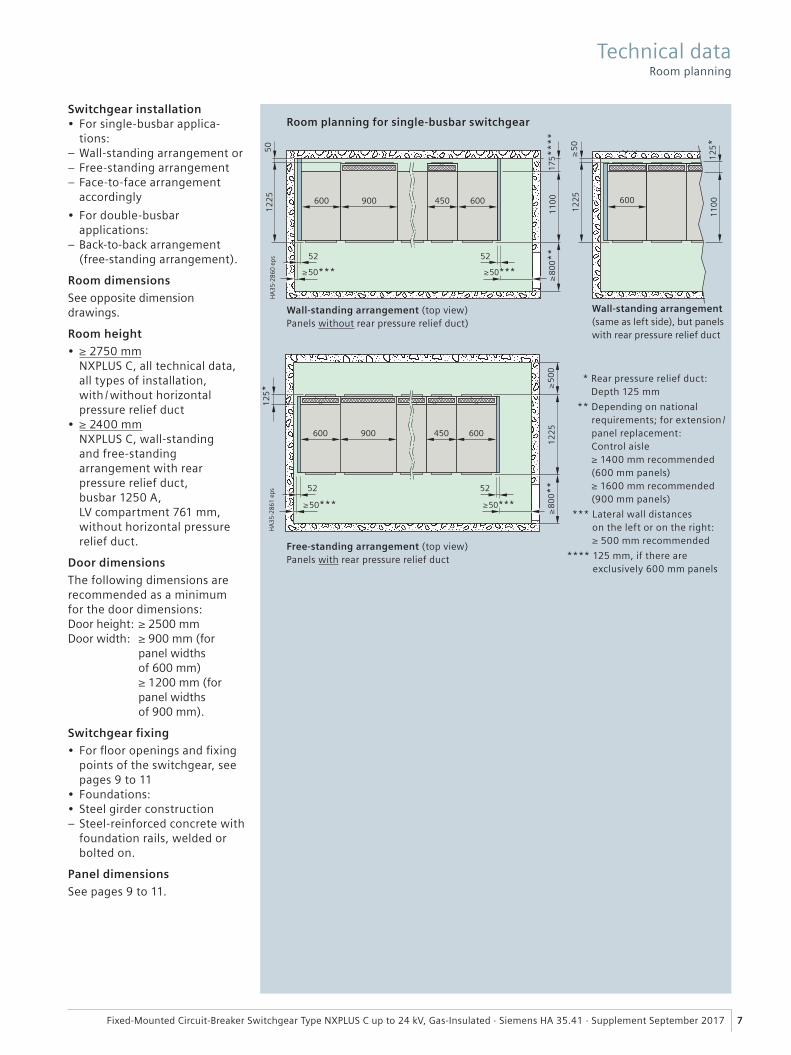
Room planning for single-busbar switchgearSwitchgear installation• For single-busbar applica-
tions: – Wall-standing arrangement or – Free-standing arrangement – Face-to-face arrangement accordingly
• For double-busbar applications:
– Back-to-back arrangement (free-standing arrangement).
Room dimensions
See opposite dimension drawings.
Room height
• ≥ 2750 mm NXPLUS C, all technical data, all types of installation, with / without horizontal pressure relief duct
• ≥ 2400 mm NXPLUS C, wall-standing and free-standing arrangement with rear pressure relief duct,busbar 1250 A, LV compartment 761 mm, without horizontal pressure relief duct.
Door dimensions
The following dimensions are recommended as a minimum for the door dimensions:Door height: ≥ 2500 mmDoor width: ≥ 900 mm (for panel widths of 600 mm) ≥ 1200 mm (for panel widths of 900 mm).
Switchgear fi xing
• For fl oor openings and fi xing points of the switchgear, see pages 9 to 11
• Foundations:• Steel girder construction
– Steel-reinforced concrete with foundation rails, welded or bolted on.
Panel dimensions
See pages 9 to 11.
Wall-standing arrangement (top view) Panels without rear pressure relief duct)
Free-standing arrangement (top view) Panels with rear pressure relief duct
Wall-standing arrangement (same as left side), but panels with rear pressure relief duct
* Rear pressure relief duct: Depth 125 mm
** Depending on national requirements; for extension /panel replacement: Control aisle ≥ 1400 mm recommended (600 mm panels) ≥ 1600 mm recommended (900 mm panels)
*** Lateral wall distances on the left or on the right: ≥ 500 mm recommended
**** 125 mm, if there are exclusively 600 mm panels
Technical data Room planning
8 Fixed-Mounted Circuit-Breaker Switchgear Type NXPLUS C up to 24 kV, Gas-Insulated · Siemens HA 35.41 · Supplement September 2017
Transport
NXPLUS C switchgear is delivered in form of individual panels. Please observe the following:
• Transport facilities on site
• Transport dimensions and transport weights
• Size of door openings in building
• Auxiliary transformer delivered separately from auxiliary transformer panel.
Packing
Means of transport: Rail and truck
– Panels on pallets – Open packing with PE protective foil.
Means of transport: Ship and airplane
– Panels on pallets – In closed crates (cardboard) with sealed upper and lower PE protective foil
– With desiccant bags – With sealed wooden base – Max. storage time: 6 months.
1) Average values depending on the degree to which panels are equipped
2) Corresponds to “metal-clad” according to former standard IEC 60298
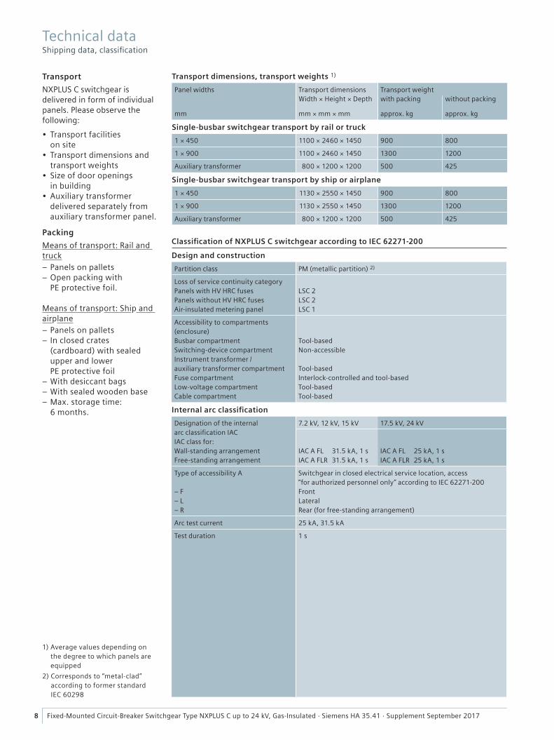
Transport dimensions, transport weights 1)
Panel widths Transport dimensions Transport weightWidth × Height × Depth with packing without packing
mm mm × mm × mm approx. kg approx. kg
Single-busbar switchgear transport by rail or truck
1 × 450 1100 × 2460 × 1450 900 800
1 × 900 1100 × 2460 × 1450 1300 1200
Auxiliary transformer 800 × 1200 × 1200 500 425
Single-busbar switchgear transport by ship or airplane
1 × 450 1130 × 2550 × 1450 900 800
1 × 900 1130 × 2550 × 1450 1300 1200
Auxiliary transformer 800 × 1200 × 1200 500 425
Classifi cation of NXPLUS C switchgear according to IEC 62271-200
Design and construction
Partition class PM (metallic partition) 2)
Loss of service continuity categoryPanels with HV HRC fusesPanels without HV HRC fusesAir-insulated metering panel
LSC 2LSC 2LSC 1
Accessibility to compartments(enclosure)Busbar compartmentSwitching-device compartmentInstrument transformer / auxiliary transformer compartmentFuse compartmentLow-voltage compartmentCable compartment
Tool-basedNon-accessible
Tool-basedInterlock-controlled and tool-basedTool-basedTool-based
Internal arc classifi cation
Designation of the internal arc classifi cation IACIAC class for:Wall-standing arrangementFree-standing arrangement
7.2 kV, 12 kV, 15 kV 17.5 kV, 24 kV
IAC A FL 31.5 kA, 1 sIAC A FLR 31.5 kA, 1 s
IAC A FL 25 kA, 1 sIAC A FLR 25 kA, 1 s
Type of accessibility A
– F– L– R
Switchgear in closed electrical service location, access “for authorized personnel only” according to IEC 62271-200FrontLateralRear (for free-standing arrangement)
Arc test current 25 kA, 31.5 kA
Test duration 1 s
Technical data Shipping data, classifi cation
���
����
����
�� �
�����
�
�
��
�
�
��
��
��
��
���
��
�
�
�
�
��
�
�
�
�
�
�
�
��
���
�
�
�
�����
���
��
�����
���
��
��
���
���
���
��
��
���
���
��
��
9Fixed-Mounted Circuit-Breaker Switchgear Type NXPLUS C up to 24 kV, Gas-Insulated · Siemens HA 35.41 · Supplement September 2017
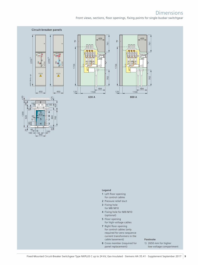
Circuit-breaker panels
630 A 800 A
Legend
1 Left fl oor opening for control cables
2 Pressure relief duct
3 Fixing hole for M8 / M10
4 Fixing hole for M8 / M10 (optional)
5 Floor opening for high-voltage cables
7 Right fl oor opening for control cables (only required for zero-sequence current transformers in the cable basement)
8 Cross member (required for panel replacement)
Footnote
1) 2650 mm for higher low-voltage compartment
Dimensions Front views, sections, fl oor openings, fi xing points for single-busbar switchgear
���
����
���
�� �
�����
��
��
��
��
��
���
��
�
�
��
��
�
�
���
�
��
�����
�
�
���
��
���
�
��
���
�
���
��
�
���
��
���
���
��
�
10 Fixed-Mounted Circuit-Breaker Switchgear Type NXPLUS C up to 24 kV, Gas-Insulated · Siemens HA 35.41 · Supplement September 2017
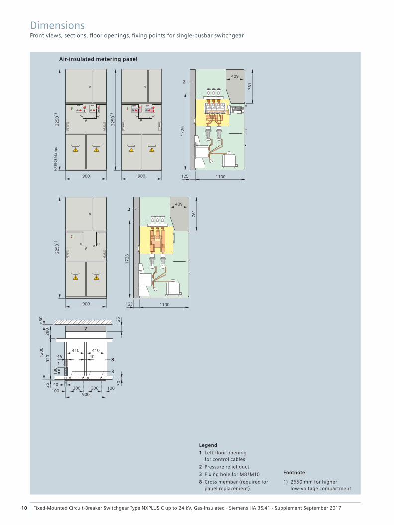
DimensionsFront views, sections, fl oor openings, fi xing points for single-busbar switchgear
Legend
1 Left fl oor opening for control cables
2 Pressure relief duct
3 Fixing hole for M8 / M10
8 Cross member (required for panel replacement)
Footnote
1) 2650 mm for higher low-voltage compartment
Air-insulated metering panel

���
����
����
�� �
�����
��
��
��
��
��
�
�
��
� ��
�
�
��
��
�
�
���
�
��
���
� �
���
��
�
���
��
���
�
�
��
���
��
�
��
�
�����
��
��
��
��
��
�
�
��
� ��
� �
��
��
�
�
���
�
��
���
� �
�
�
���
���
����
����
�� �
���
��
�
���
��
�
��
���
�
�
�� ��
�
�
11Fixed-Mounted Circuit-Breaker Switchgear Type NXPLUS C up to 24 kV, Gas-Insulated · Siemens HA 35.41 · Supplement September 2017
DimensionsFront views, sections, fl oor openings, fi xing points for single-busbar switchgear
Auxiliary transformer panel
Legend
1 Floor opening for control cables
2 Pressure relief duct
3 Fixing hole for M8 / M10
5 Floor opening for high-voltage cables
8 Cross member (required for panel replacement)
Footnote
1) 2650 mm for higher low-voltage compartment
���
���
���
�
����
����
����
����
���
���
����
� �
���
���
����
� �
������
12 Fixed-Mounted Circuit-Breaker Switchgear Type NXPLUS C up to 24 kV, Gas-Insulated · Siemens HA 35.41 · Supplement September 2017
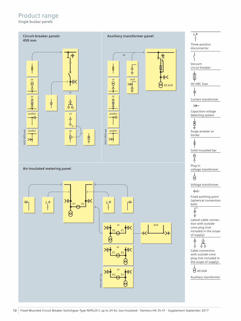
Circuit-breaker panels450 mm
Auxiliary transformer panel
Air-insulated metering panel
Product range Single-busbar panels
or
or
or
and
Three-positiondisconnector
Vacuum circuit-breaker
HV HRC fuse
Current transformer
Capacitive voltage detecting system
Surge arrester or limiter
Solid-insulated bar
Plug-in voltage transformer
Voltage transformer
Fixed earthing point (spherical connection bolt)
Lateral cable connec-tion with outside-cone plug (not included in the scope of supply)
Cable connection with outside-cone plug (not included in the scope of supply)
40 kVA
Auxiliary transformer
or or and
or
or
or
or
or
and/or and/or
and/or and/or
���
����
����
� �
�
��
��
��
�
��
��
��
�
��
�
��
��
�
��
��
�
��
�
�
�
�
�
����
��
�
��
�
��
��
��
13Fixed-Mounted Circuit-Breaker Switchgear Type NXPLUS C up to 24 kV, Gas-Insulated · Siemens HA 35.41 · Supplement September 2017
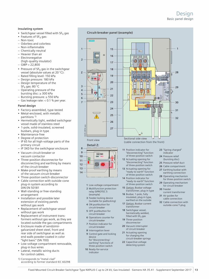
Insulating system
• Switchgear vessel fi lled with SF6 gas• Features of SF6 gas:
– Non-toxic – Odorless and colorless – Non-infl ammable – Chemically neutral – Heavier than air – Electronegative (high-quality insulator)
– GWP = 22,800
• Pressure of SF6 gas in the switchgear vessel (absolute values at 20 °C):
– Rated fi lling level: 150 kPa – Design pressure: 180 kPa – Design temperature of the SF6 gas: 80 °C
– Operating pressure of the bursting disc: ≥ 300 kPa
– Bursting pressure: ≥ 550 kPa – Gas leakage rate: < 0.1 % per year.
Panel design• Factory-assembled, type-tested• Metal-enclosed, with metallic
partitions 1)
• Hermetically tight, welded switchgear vessel made of stainless steel
• 1-pole, solid-insulated, screened busbars, plug-in type
• Maintenance-free• Degree of protection
– IP 65 for all high-voltage parts of the primary circuit
– IP 3XD for the switchgear enclosure
• Vacuum circuit-breaker or vacuum contactor
• Three-position disconnector for disconnecting and earthing by means of the circuit-breaker
• Make-proof earthing by means of the vacuum circuit-breaker
• Three-position switch-disconnector• Cable connection with outside-cone
plug-in system according to DIN EN 50181
• Wall-standing or free-standing arrangement
• Installation and possible later extension of existing panels without gas work
• Replacement of switchgear vessel without gas work
• Replacement of instrument trans-formers without gas work, as they are located outside the gas compartments
• Enclosure made of sendzimir-galvanized sheet steel, front and rear side of switchgear as well as end walls powder-coated in color “light basic” (SN 700)
• Low-voltage compartment removable, plug-in bus wires
• Lateral, metallic wiring ducts for control cables.
Circuit-breaker panel (example)
Front view
Detail Z:
Sectional side view (cable connection from the front)
1 Low-voltage compartment 2 Multifunction protection
relay SIPROTEC 5 (example)
3 Feeder locking device (suitable for padlocking)
4 ON pushbutton for circuit-breaker
5 OFF pushbutton for circuit-breaker
6 Operations counter for circuit-breaker
7 Position indicator for circuit-breaker
8 Interrogation lever 9 Control gate and locking
device for “disconnecting /earthing” functions of three-position switch
10 Ready-for-serviceindicator
11 Position indicator for “disconnecting” function of three-position switch
12 Actuating opening for “disconnecting” function of three-position switch
13 Actuating opening for “ready-to-earth” function of three-position switch
14 Position indicator for “ready-to-earth” function of three-position switch
15 Option: Busbar voltage transformer, plug-in type
16 Busbar, 1-pole, fully insulated, plug-in type, earthed on the outside
17 Option: Busbar current transformer
18 Switchgear vessel, hermetically welded, filled with SF6 gas
19 Three-position disconnector
20 Vacuum interrupter of circuit-breaker
21 Actuating opening for charging the circuit-breaker springs
22 Capacitive voltage detecting system
23 “Spring charged” indicator
24 Pressure relief (bursting disc)
25 Pressure relief duct 26 Cable compartment 27 Earthing busbar with
earthing connection 28 Operating mechanism
for three-position switch 29 Operating mechanism
for circuit-breaker 30 Feeder
current transformer 31 Air guides for
cable connection 32 Cable connection with
outside-cone T-plug
1) Corresponds to “metal-clad” according to former standard IEC 60298
Design Basic panel design
���
����
����
�
� �� � ���
�� � �
R-H
A3
541
-18
6 t
if
7
9
6 8
2
4
10
3
1
11
5
14 Fixed-Mounted Circuit-Breaker Switchgear Type NXPLUS C up to 24 kV, Gas-Insulated · Siemens HA 35.41 · Supplement September 2017
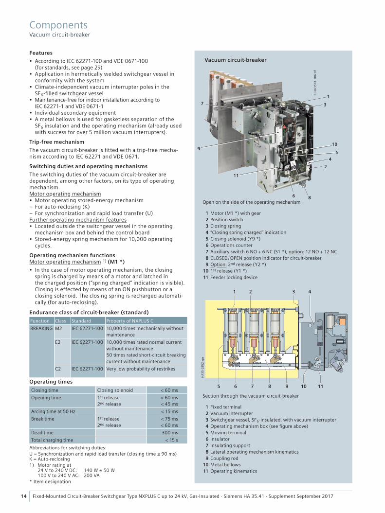
Vacuum circuit-breakerFeatures
• According to IEC 62271-100 and VDE 0671-100 (for standards, see page 29)
• Application in hermetically welded switchgear vessel in conformity with the system
• Climate-independent vacuum interrupter poles in the SF6-fi lled switchgear vessel
• Maintenance-free for indoor installation according to IEC 62271-1 and VDE 0671-1
• Individual secondary equipment• A metal bellows is used for gasketless separation of the
SF6 insulation and the operating mechanism (already used with success for over 5 million vacuum interrupters).
Trip-free mechanism
The vacuum circuit-breaker is fi tted with a trip-free mecha-nism according to IEC 62271 and VDE 0671.
Switching duties and operating mechanisms
The switching duties of the vacuum circuit-breaker are dependent, among other factors, on its type of operating mechanism.Motor operating mechanism• Motor operating stored-energy mechanism
– For auto-reclosing (K) – For synchronization and rapid load transfer (U)
Further operating mechanism features• Located outside the switchgear vessel in the operating
mechanism box and behind the control board• Stored-energy spring mechanism for 10,000 operating
cycles.
Operating mechanism functionsMotor operating mechanism 1) (M1 *)
• In the case of motor operating mechanism, the closing spring is charged by means of a motor and latched in the charged position (“spring charged” indication is visible). Closing is effected by means of an ON pushbutton or a closing solenoid. The closing spring is recharged automati-cally (for auto-reclosing).
Endurance class of circuit-breaker (standard)
Function Class Standard Property of NXPLUS C
BREAKING M2 IEC 62271-100 10,000 times mechanically without maintenance
E2 IEC 62271-100 10,000 times rated normal current without maintenance 50 times rated short-circuit breaking current without maintenance
C2 IEC 62271-100 Very low probability of restrikes
Operating times
Closing time Closing solenoid < 60 ms
Opening time 1st release2nd release
< 60 ms< 45 ms
Arcing time at 50 Hz < 15 ms
Break time 1st release2nd release
< 75 ms< 60 ms
Dead time 300 ms
Total charging time < 15 s
1 Motor (M1 *) with gear 2 Position switch 3 Closing spring 4 “Closing spring charged“ indication 5 Closing solenoid (Y9 *) 6 Operations counter 7 Auxiliary switch 6 NO + 6 NC (S1 *), option: 12 NO + 12 NC 8 CLOSED / OPEN position indicator for circuit-breaker 9 Option: 2nd release (Y2 *) 10 1st release (Y1 *) 11 Feeder locking device
Section through the vacuum circuit-breaker
Open on the side of the operating mechanism
Abbreviations for switching duties:U = Synchronization and rapid load transfer (closing time ≤ 90 ms)K = Auto-reclosing1) Motor rating at
24 V to 240 V DC: 140 W ± 50 W100 V to 240 V AC: 200 VA
* Item designation
Components Vacuum circuit-breaker
1 Fixed terminal 2 Vacuum interrupter 3 Switchgear vessel, SF6-insulated, with vacuum interrupter 4 Operating mechanism box (see figure above) 5 Moving terminal 6 Insulator 7 Insulating support 8 Lateral operating mechanism kinematics 9 Coupling rod 10 Metal bellows 11 Operating kinematics
15Fixed-Mounted Circuit-Breaker Switchgear Type NXPLUS C up to 24 kV, Gas-Insulated · Siemens HA 35.41 · Supplement September 2017
Secondary equipmentThe scope of the secondary equipment of the vacuum circuit-breaker depends on the type of application and offers a wide range of possible variations, allowing almost every requirement to be satisfi ed:Closing solenoid• Type 3AY14 10 (Y9 *)• For electrical closing.
Shunt release• Types:
– Standard: 3AY14 10 (Y1 *)– Option: 3AX11 01 (Y2 *), with energy store
• Tripping by protection relay or electrical actuation.
C.t.-operated release• Type 3AX11 02 (Y4 *), 0.5 A• Type 3AX11 04 (Y6 *) for tripping pulse ≥ 0.1 Ws
in conjunction with suitable protection systems• Used if external auxiliary voltage is missing, tripping via
protection relay.
Undervoltage release• Type 3AX11 03 (Y7 *)• Comprising:
– Energy store and unlatching mechanism – Electromagnetic system, which is permanently connected to voltage while the vacuum circuit-breaker is closed; tripping is initiated when this voltage drops
• Connection to voltage transformers possible.
Anti-pumping (mechanical and electrical)• Function: If constant CLOSE and OPEN commands are
present at the vacuum circuit-breaker at the same time, the vacuum circuit-breaker will return to the open position after closing. It remains in this position until a new CLOSE command is given. In this manner, continuous closing and opening (= pumping) is avoided.
Circuit-breaker tripping signal• For electrical signaling (as pulse > 5 ms), e.g. to remote
control systems, in the case of automatic tripping (e.g. protection)
• Via limit switch (S6 *).
Varistor module• To limit overvoltages to approx. 500 V for protection devices
(when inductive components are mounted in the vacuum circuit-breaker)
• For auxiliary voltages ≥ 60 V DC.
Auxiliary switch• Type 3SV9 (S1 *)• Standard: 6 NO + 6 NC, free contacts thereof 1) 3 NO + 4 NC• Option: 12 NO + 12 NC, free contacts thereof 1) 9 NO + 6 NC.
Position switch• Type 3SE4 (S4 *, S16*)• For signaling “closing spring charged”• For “circuit-breaker blocked” indication.
Mechanical interlocking• Mechanical interlocking to the three-position disconnector• During operation of the three-position switch, the vacuum
circuit-breaker cannot be operated.
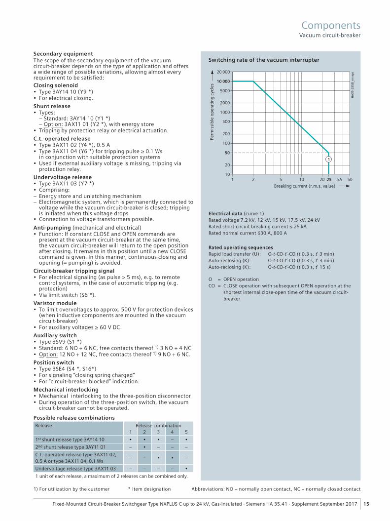
Switching rate of the vacuum interrupter
Electrical data (curve 1)Rated voltage 7.2 kV, 12 kV, 15 kV, 17.5 kV, 24 kVRated short-circuit breaking current ≤ 25 kA Rated normal current 630 A, 800 A
Rated operating sequencesRapid load transfer (U): O-t-CO-t‘-CO (t 0.3 s, t‘ 3 min)Auto-reclosing (K): O-t-CO-t‘-CO (t 0.3 s, t‘ 3 min)Auto-reclosing (K): O-t-CO-t‘-CO (t 0.3 s, t‘ 15 s)
O = OPEN operationCO = CLOSE operation with subsequent OPEN operation at the
shortest internal close-open time of the vacuum circuit-breaker
Possible release combinationsRelease
1 2 3 4 5
1st shunt release type 3AY14 10 • • • – •
2nd shunt release type 3AY11 01 – • – – –
C.t.-operated release type 3AX11 02, 0.5 A or type 3AX11 04, 0.1 Ws
– – • • –
Undervoltage release type 3AX11 03 – – – – •
1 unit of each release, a maximum of 2 releases can be combined only.
Release combination
1) For utilization by the customer * Item designation Abbreviations: NO = normally open contact, NC = normally closed contact
ComponentsVacuum circuit-breaker
���
����
��
� �
���
���
����
�
R-H
A3
541
-18
7 t
ifR-
HA
35
41
-18
8 t
if
4
4
3
3
2
2
1
1
16 Fixed-Mounted Circuit-Breaker Switchgear Type NXPLUS C up to 24 kV, Gas-Insulated · Siemens HA 35.41 · Supplement September 2017
Common features
• According to IEC 62271-102 and VDE 0671-102 (for standards, see page 29)
• Application in hermetically welded switchgear vessel in conformity with the system
• Climate-independent contacts in the SF6-fi lled switchgear vessel
• Maintenance-free for indoor installation according to IEC 62271-1 and VDE 0671-1
• Individual secondary equipment• A rotary bushing is used for separation of the
SF6 insulation and the operating mechanism (already used with success millions of times in medium-voltage and high-voltage switchgear)
• Compact design due to short contact gaps in SF6 gas• Operation via rotary bushing welded gas-tight into the
front of the switchgear vessel• Reliable mechanical switch position up to the operating
front of the panel.
Three-position disconnector
• Application in: – Circuit-breaker panel 630 A, 800 A – Air-insulated metering panel
• 2000 mechanical operating cycles for CLOSE / OPEN• 1000 mechanical operating cycles
for OPEN / READY-TO-EARTH.
Three-position switch-disconnector
• Application in auxiliary transformer panel• 1000 mechanical operating cycles for CLOSE / OPEN• 1000 mechanical operating cycles
for OPEN / READY-TO-EARTH• Switching functions as general-purpose switch-
disconnector according to – IEC 62271-103 – VDE 0670-301 – IEC 62271-102 – VDE 0671-102 (for standards, see page 29)
• Designed as a three-position switch with the functions – Switch-disconnector and – Make-proof earthing switch.
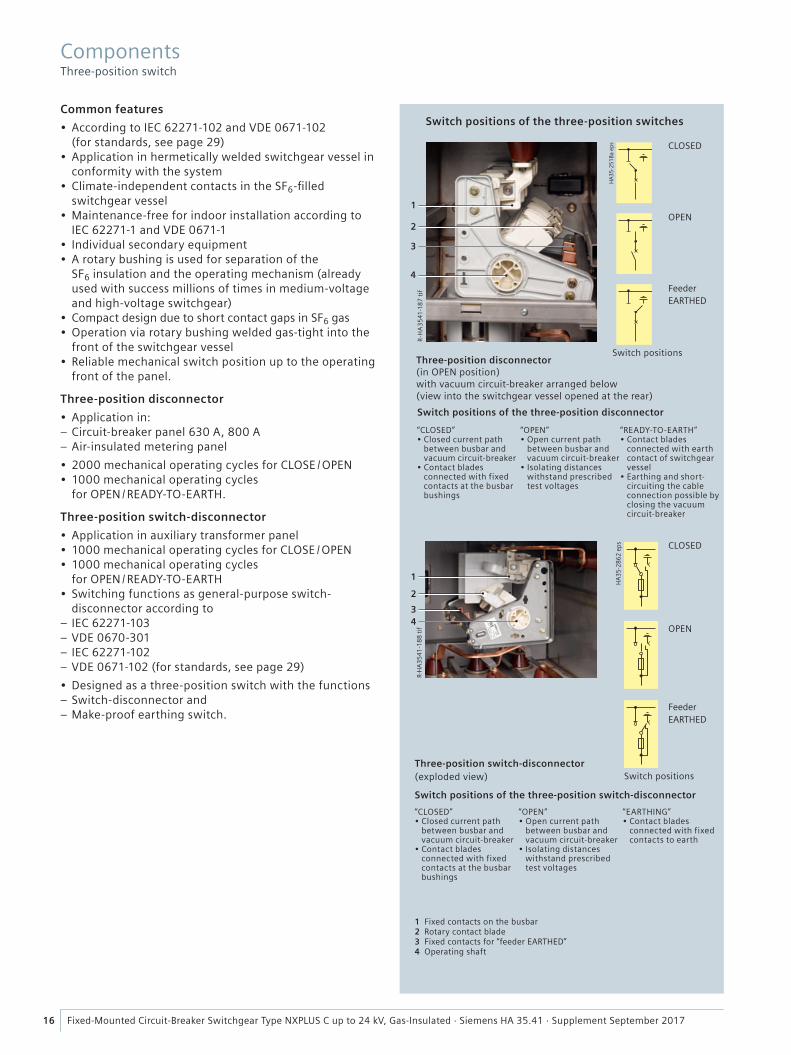
Three-position disconnector(in OPEN position) with vacuum circuit-breaker arranged below (view into the switchgear vessel opened at the rear)
Switch positions of the three-position switches
CLOSED
OPEN
Feeder EARTHED
Switch positions
CLOSED
OPEN
Feeder EARTHED
Switch positions
Switch positions of the three-position disconnector
Switch positions of the three-position switch-disconnector
“CLOSED”• Closed current path
between busbar and vacuum circuit-breaker
• Contact blades connected with fixed contacts at the busbar bushings
“OPEN”• Open current path
between busbar and vacuum circuit-breaker
• Isolating distanceswithstand prescribedtest voltages
“READY-TO-EARTH”• Contact blades
connected with earth contact of switchgear vessel
• Earthing and short-circuiting the cableconnection possible byclosing the vacuumcircuit-breaker
“CLOSED”• Closed current path
between busbar and vacuum circuit-breaker
• Contact blades connected with fixed contacts at the busbar bushings
“OPEN”• Open current path
between busbar and vacuum circuit-breaker
• Isolating distanceswithstand prescribedtest voltages
“EARTHING”• Contact blades
connected with fixed contacts to earth
1 Fixed contacts on the busbar2 Rotary contact blade3 Fixed contacts for “feeder EARTHED”4 Operating shaft
Three-position switch-disconnector(exploded view)
Components Three-position switch
���
����
���
� �
�
�
���
����
���
�
�
�
17Fixed-Mounted Circuit-Breaker Switchgear Type NXPLUS C up to 24 kV, Gas-Insulated · Siemens HA 35.41 · Supplement September 2017
Interlocks
• Selection of permissible switching operations by means of a control gate with mechanically interlocked vacuum circuit-breaker
• The corresponding operating shafts are not released at the operating front until they have been pre-selected with the control gate
• Operating lever cannot be removed until switching operation has been completed
• Circuit-breaker cannot be closed until control gate is in neutral position again
• Switchgear interlocking system also possible with electromechanical interlocks if switchgear is equipped with motor operating mechanisms (mechanical inter-locking for manual operation remains).
Switch positions
• “CLOSED”, “OPEN”, “EARTHED” or “READY-TO-EARTH”• In circuit-breaker panels, earthing and short-circuiting
the cable connection is completed by closing the vacuum circuit-breaker.
Operating mechanism
• Slow motion mechanism, used in: – Circuit-breaker panel 630 A, 800 A – Air-insulated metering panel
• Spring-operated /stored-energy mechanism, used in: – Auxiliary transformer panel
• Slow motion mechanism actuated via operating lever at the operating front of the panel
• Separate operating shafts for the “DISCONNECTING” and “READY-TO-EARTH” functions
• Option: Motor operating mechanism for the “DISCONNECTING” and “READY-TO-EARTH” functions
• Spring-operated /stored-energy mechanism for the switch-disconnector function with fuses:
– The switching movements are performed independently of the operating speed
– During the charging process, the closing and opening springs are charged. This ensures that the switch- disconnector / fuse combination can switch off all types of faults reliably even during closing
– Closing and opening is done via pushbuttons, and is therefore identical with the operation of circuit-breaker operating mechanisms
– An energy store is available for tripping by means of an operating HV HRC fuse, or tripping via shunt release (f-release)
– After tripping, a red bar appears on the position indicator – Operation of the switch-disconnector “READY-TO-EARTH” function with spring-operated mechanism and operating lever
• Maintenance-free due to non-rusting design of parts subjected to mechanical stress
• Bearings which require no lubrication.
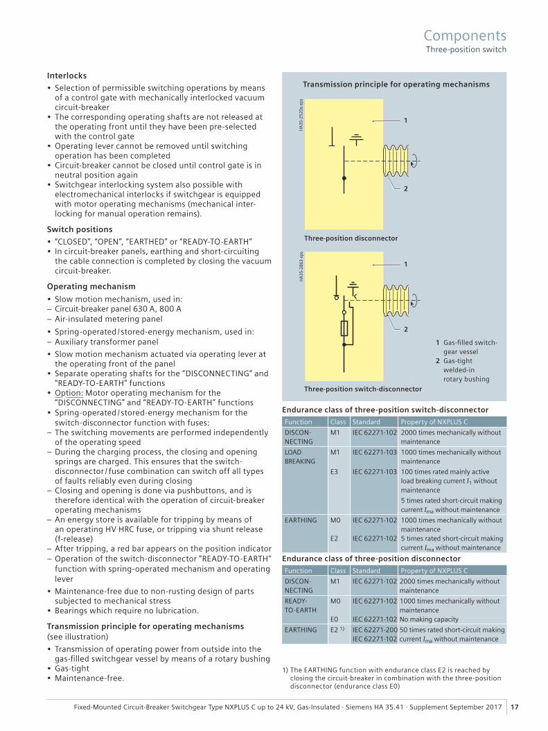
Transmission principle for operating mechanisms (see illustration)
• Transmission of operating power from outside into the gas-fi lled switchgear vessel by means of a rotary bushing
• Gas-tight• Maintenance-free.
Endurance class of three-position disconnector
Function Class Standard Property of NXPLUS C
DISCON-NECTING
M1 IEC 62271-102 2000 times mechanically without maintenance
READY-TO-EARTH
M0
E0
IEC 62271-102
IEC 62271-102
1000 times mechanically without maintenanceNo making capacity
EARTHING E2 1) IEC 62271-200IEC 62271-102
50 times rated short-circuit making current Ima without maintenance
Endurance class of three-position switch-disconnector
Function Class Standard Property of NXPLUS C
DISCON-NECTING
M1 IEC 62271-102 2000 times mechanically without maintenance
LOAD BREAKING
M1
E3
IEC 62271-103
IEC 62271-103
1000 times mechanically without maintenance
100 times rated mainly active load breaking current I1 without maintenance
5 times rated short-circuit making current Ima without maintenance
EARTHING M0
E2
IEC 62271-102
IEC 62271-102
1000 times mechanically without maintenance5 times rated short-circuit making current Ima without maintenance
1) The EARTHING function with endurance class E2 is reached by closing the circuit-breaker in combination with the three-position disconnector (endurance class E0)
Transmission principle for operating mechanisms
1 Gas-fi lled switch-gear vessel
2 Gas-tight welded-in rotary bushing
Three-position switch-disconnector
Three-position disconnector
ComponentsThree-position switch
����������� �
� � �
��� ���
����
����
��
�
18 Fixed-Mounted Circuit-Breaker Switchgear Type NXPLUS C up to 24 kV, Gas-Insulated · Siemens HA 35.41 · Supplement September 2017
Features
• Application in: – Auxiliary transformer panel
• HV HRC fuse-links according to DIN 43 625 (main dimen-sions) with striker in “medium” version according to IEC 60282 / VDE 0670-4
– As short-circuit protection before transformers in the auxiliary transformer panel
– 1-pole insulated
• Requirements according to IEC 62271-105 and VDE 0671-105 met by the combination of HV HRC fuses with the three-position switch-disconnector
• Climate-independent and maintenance-free, with fuse boxes made of cast resin
• Fuse assembly connected to the three-position switch- disconnector via welded-in bushings and connecting bars
• Arrangement of fuse assembly below the switchgear vessel• Fuse replacement possible only when the transformer is
earthed• Option: “Fuse tripped” indication for remote electrical
indication with 1 NO contact.
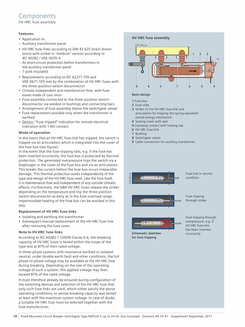
Mode of operation
In the event that an HV HRC fuse-link has tripped, the switch is tripped via an articulation which is integrated into the cover of the fuse box (see fi gure).In the event that the fuse tripping fails, e.g. if the fuse has been inserted incorrectly, the fuse box is protected by thermal protection. The generated overpressure trips the switch via a diaphragm in the cover of the fuse box and via an articulation. This breaks the current before the fuse box incurs irreparable damage. This thermal protection works independently of the type and design of the HV HRC fuse used. Like the fuse itself, it is maintenance-free and independent of any outside climatic effects. Furthermore, the SIBA HV HRC fuses release the striker depending on the temperature and trip the three-position switch-disconnector as early as in the fuse overload range. Impermissible heating of the fuse box can be avoided in this way.
Replacement of HV HRC fuse-links
• Isolating and earthing the transformer• Subsequent manual replacement of the HV HRC fuse-link
after removing the fuse cover.
Note to HV HRC fuse-links
According to IEC 60282-1 (2009) Clause 6.6, the breaking capacity of HV HRC fuses is tested within the scope of the type test at 87% of their rated voltage.
In three-phase systems with resonance-earthed or isolated neutral, under double earth fault and other conditions, the full phase-to-phase voltage may be available at the HV HRC fuse during breaking. Depending on the size of the operating voltage of such a system, this applied voltage may then exceed 87% of the rated voltage.
It must therefore already be ensured during confi guration of the switching devices and selection of the HV HRC fuse that only such fuse-links are used, which either satisfy the above operating conditions, or whose breaking capacity was tested at least with the maximum system voltage. In case of doubt, a suitable HV HRC fuse must be selected together with the fuse manufacturer.
HV HRC fuse assembly
Basic design
1 Fuse box2 Fuse slide3 Striker of the HV HRC fuse-link and
articulation for tripping the spring-operated /stored-energy mechanism
4 Sealing cover with seal5 Clamping contact with locking cap6 HV HRC fuse-link7 Bushing8 Switchgear vessel9 Cable connection for auxiliary transformer
Schematic sketches for fuse tripping
Fuse-link in service condition
Fuse tripping through striker
Fuse tripping through overpressure, e.g. if HV HRC fuse-link has been inserted incorrectly
Components HV HRC fuse assembly

���
����
���
��
�
�
�
�
�
�
�
�
���
����
���
�
�
�
�
�
19Fixed-Mounted Circuit-Breaker Switchgear Type NXPLUS C up to 24 kV, Gas-Insulated · Siemens HA 35.41 · Supplement September 2017
Features
• According to IEC 61869-2 and VDE 0414-9-2
• Designed as ring-core current transformers, 1-pole
• Free of dielectrically stressed cast-resin parts (due to design)
• Insulation class E• Inductive type• Certifi able• Climate-independent• Secondary connection by
means of a terminal strip in the low-voltage compart-ment of the panel.
Installation
• Arranged outside the primary enclosure (switchgear vessel).
Mounting locations
• At the busbar (1)• At the panel connection (2)• Around the cable (3).
Current transformer types
• Busbar current transformer (1):
– Inside diameter of trans-former56 mm / ≤ 1250 A and55 × 355 mm / > 1250 A
– Usable height max. 160 mm for ≤ 1250 A,max. 130 mm for > 1250 A
• Feeder current transformer (2)
– Inside diameter of trans-former 102 mm / ≤ 800 A
– Max. usable height 122 mm
• Cable-type current trans-former (3) for shielded cables:
– Inside diameter of trans-former 55 mm
– Max. usable height 55 mm
• Zero-sequence current transformer (4) underneath the panels (included in the scope of supply); on-site installation.
Busbar current transformer Example 1250 A
Front views:
630 A, 800 A 630 A and 800 A
Current transformer installation (basic scheme)
Panel with 1250 A busbar
Panel with 2500 A busbar
Electrical data
Designation type 4MC
Operating voltage max. 0.8 kV
Rated short-durationpower-frequency withstand voltage (winding test)
3 kV
Rated frequency 50 / 60 Hz
Rated continuous thermal current
1.0; 1.2; 1.33; 1.5; 2.0 × rated current (primary)
Rated short-time thermal current, max. 3 s
max. 31.5 kA
Rated dynamic current primary secondary
unlimited,40 A to 2500 A 1 A and 5 A
Current transformers
1 Busbar current transformer2 Feeder current transformer
at the panel connection3 Cable-type current transformer4 Zero-sequence current transformer
Components Current transformers
Designation type 4MC
Multiratio (secondary) 200 A – 100 A to 2500 A – 1250 A
Core data depending on the rated primary current:
max. 3 cores
Measuring core
RatingClassOvercurrent factor
2.5 VA to 30 VA0.2 to 1
FS 5, FS 10
Protection core
RatingClassOvercurrent factor
2.5 VA to 30 VA5 P or 10 P
10 to 30
Permissible ambient air temperature
max. 60 °C
Insulation class E
20 Fixed-Mounted Circuit-Breaker Switchgear Type NXPLUS C up to 24 kV, Gas-Insulated · Siemens HA 35.41 · Supplement September 2017
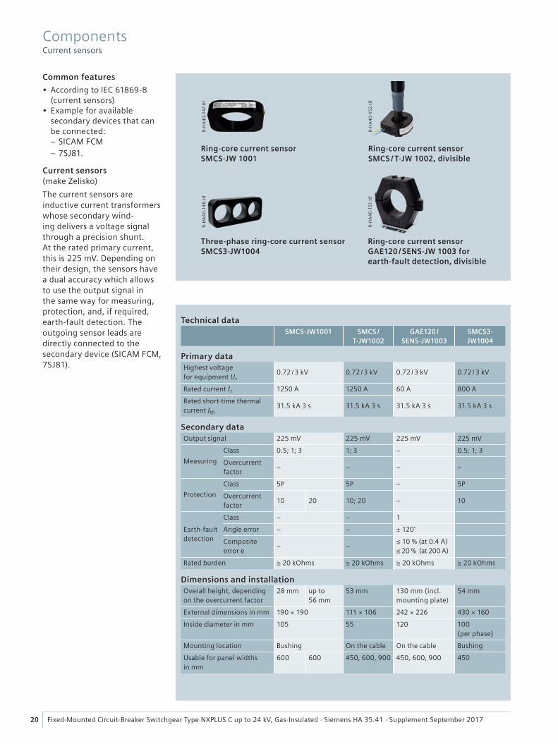
Common features
• According to IEC 61869-8 (current sensors)
• Example for available secondary devices that can be connected:
– SICAM FCM – 7SJ81.
Current sensors (make Zelisko)
The current sensors are inductive current trans formers whose secondary wind-ing delivers a voltage signal through a precision shunt. At the rated primary current, this is 225 mV. Depending on their design, the sensors have a dual accuracy which allows to use the output signal in the same way for measuring, protection, and, if required, earth-fault detection. The outgoing sensor leads are directly connected to the secondary device (SICAM FCM, 7SJ81).
Technical dataSMCS-JW1001 SMCS /
T-JW1002GAE120 /
SENS-JW1003SMCS3-JW1004
Primary dataHighest voltage for equipment Ur
0.72 / 3 kV 0.72 / 3 kV 0.72 / 3 kV 0.72 / 3 kV
Rated current Ir 1250 A 1250 A 60 A 800 A
Rated short-time thermal current Ith
31.5 kA 3 s 31.5 kA 3 s 31.5 kA 3 s 31.5 kA 3 s
Secondary dataOutput signal 225 mV 225 mV 225 mV 225 mV
Measuring
Class 0.5; 1; 3 1; 3 – 0.5; 1; 3
Overcurrent factor
– – – –
Protection
Class 5P 5P – 5P
Overcurrent factor
10 20 10; 20 – 10
Earth-fault detection
Class – – 1
Angle error – – ± 120'
Composite error e
– –≤ 10 % (at 0.4 A)≤ 20 % (at 200 A)
Rated burden ≥ 20 kOhms ≥ 20 kOhms ≥ 20 kOhms ≥ 20 kOhms
Dimensions and installationOverall height, depending on the overcurrent factor
28 mm up to 56 mm
53 mm 130 mm (incl. mounting plate)
54 mm
External dimensions in mm 190 × 190 111 × 106 242 × 226 430 × 160
Inside diameter in mm 105 55 120 100 (per phase)
Mounting location Bushing On the cable On the cable Bushing
Usable for panel widths in mm
600 600 450, 600, 900 450, 600, 900 450
Ring-core current sensor SMCS-JW 1001
Three-phase ring-core current sensor SMCS3-JW1004
Ring-core current sensor SMCS / T-JW 1002, divisible
Ring-core current sensor GAE120 / SENS-JW 1003 for earth-fault detection, divisible
R-H
A4
0-1
47.t
ifR
-HA
40
-14
8.t
if
R-H
A4
0-1
52
.tif
R-H
A4
0-1
51.t
if
Components Current sensors
21Fixed-Mounted Circuit-Breaker Switchgear Type NXPLUS C up to 24 kV, Gas-Insulated · Siemens HA 35.41 · Supplement September 2017
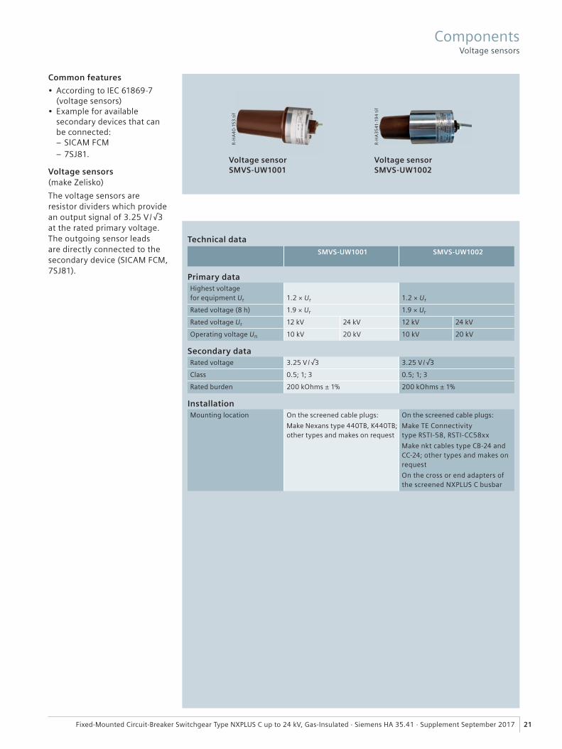
Common features
• According to IEC 61869-7 (voltage sensors)
• Example for available secondary devices that can be connected:
– SICAM FCM – 7SJ81.
Voltage sensors (make Zelisko)
The voltage sensors are resistor dividers which provide an output signal of 3.25 V /√3 at the rated primary voltage. The outgoing sensor leads are directly connected to the secondary device (SICAM FCM, 7SJ81).
Primary dataHighest voltage for equipment Ur 1.2 × Ur 1.2 × Ur
Rated voltage (8 h) 1.9 × Ur 1.9 × Ur
Rated voltage Ur 12 kV 24 kV 12 kV 24 kV
Operating voltage Un 10 kV 20 kV 10 kV 20 kV
Secondary dataRated voltage 3.25 V / √3 3.25 V / √3
Class 0.5; 1; 3 0.5; 1; 3
Rated burden 200 kOhms ± 1% 200 kOhms ± 1%
InstallationMounting location On the screened cable plugs:
Make Nexans type 440TB, K440TB; other types and makes on request
On the screened cable plugs:
Make TE Connectivity type RSTI-58, RSTI-CC58xx
Make nkt cables type CB-24 and CC-24; other types and makes on request
On the cross or end adapters of the screened NXPLUS C busbar
Technical dataSMVS-UW1001 SMVS-UW1002
Voltage sensor SMVS-UW1001
R-H
A4
0-1
53
.tif
Components Voltage sensors
Voltage sensor SMVS-UW1002
R-H
A3
541
-19
4 t
if
� �
���
����
����
� �
� �
���
����
���
� �
3
3
2
1
4
R-H
A3
541
-191
tif
R-H
A3
541
-193
tif
22 Fixed-Mounted Circuit-Breaker Switchgear Type NXPLUS C up to 24 kV, Gas-Insulated · Siemens HA 35.41 · Supplement September 2017
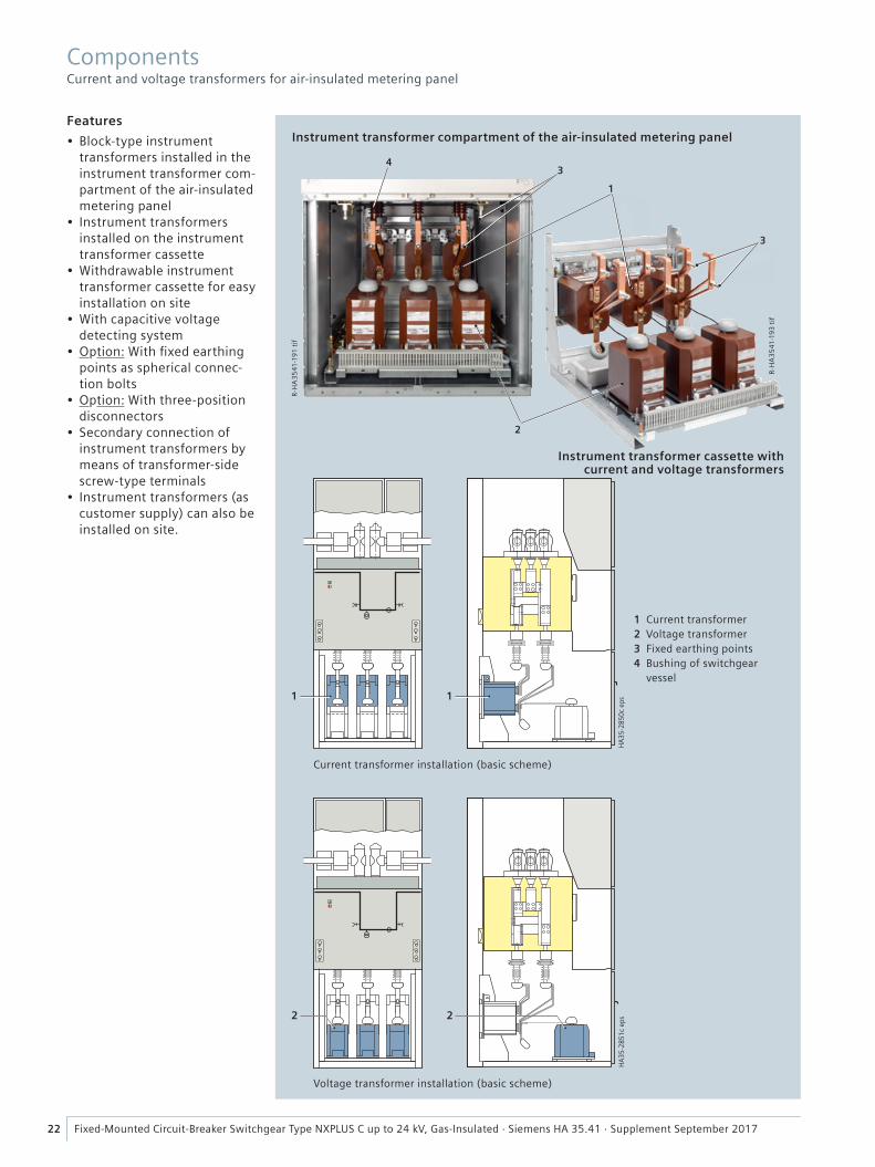
Features
• Block-type instrument transformers installed in the instrument transformer com-partment of the air-insulated metering panel
• Instrument transformers installed on the instrument transformer cassette
• Withdrawable instrument transformer cassette for easy installation on site
• With capacitive voltage detecting system
• Option: With fi xed earthing points as spherical connec-tion bolts
• Option: With three-position disconnectors
• Secondary connection of instrument transformers by means of transformer-side screw-type terminals
• Instrument transformers (as customer supply) can also be installed on site.
Current transformer installation (basic scheme)
Instrument transformer cassette with current and voltage transformers
Instrument transformer compartment of the air-insulated metering panel
Voltage transformer installation (basic scheme)
1 Current transformer2 Voltage transformer3 Fixed earthing points4 Bushing of switchgear
vessel
Components Current and voltage transformers for air-insulated metering panel
23Fixed-Mounted Circuit-Breaker Switchgear Type NXPLUS C up to 24 kV, Gas-Insulated · Siemens HA 35.41 · Supplement September 2017
Components Current and voltage transformers for air-insulated metering panel
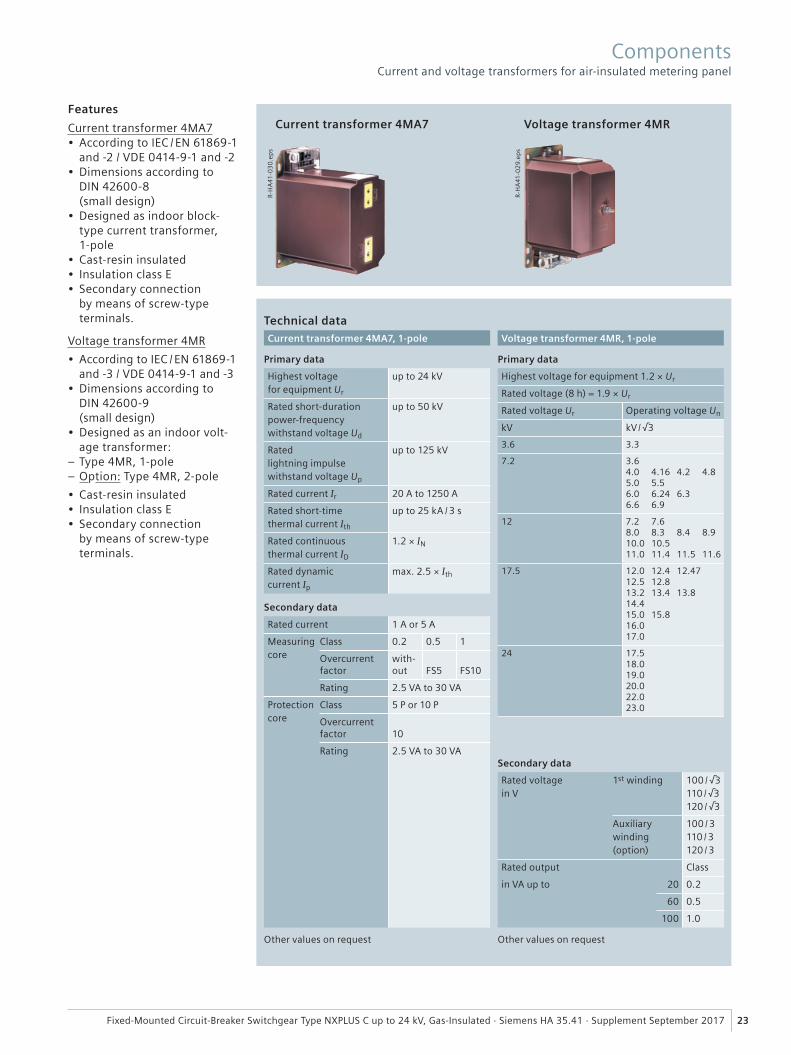
Features
Current transformer 4MA7• According to IEC / EN 61869-1
and -2 / VDE 0414-9-1 and -2• Dimensions according to
DIN 42600-8 (small design)
• Designed as indoor block-type current transformer, 1-pole
• Cast-resin insulated• Insulation class E• Secondary connection
by means of screw-type terminals.
Voltage transformer 4MR
• According to IEC / EN 61869-1 and -3 / VDE 0414-9-1 and -3
• Dimensions according to DIN 42600-9 (small design)
• Designed as an indoor volt-age transformer:
– Type 4MR, 1-pole – Option: Type 4MR, 2-pole
• Cast-resin insulated• Insulation class E• Secondary connection
by means of screw-type terminals.
Technical dataCurrent transformer 4MA7, 1-pole
Primary data
Highest voltage for equipment Ur
up to 24 kV
Rated short-duration power-frequency withstand voltage Ud
up to 50 kV
Rated lightning impulse withstand voltage Up
up to 125 kV
Rated current Ir 20 A to 1250 A
Rated short-time thermal current Ith
up to 25 kA / 3 s
Rated continuous thermal current ID
1.2 × IN
Rated dynamic current Ip
max. 2.5 × Ith
Secondary data
Rated current 1 A or 5 A
Measuring core
Class 0.2 0.5 1
Overcurrent factor
with-out FS5 FS10
Rating 2.5 VA to 30 VA
Protection core
Class 5 P or 10 P
Overcurrent factor 10
Rating 2.5 VA to 30 VA
Other values on request
Current transformer 4MA7 Voltage transformer 4MR
R-H
A41
-03
0.e
ps
R-H
A41
-02
9.ep
s
Secondary data
Rated voltage in V
1st winding 100 / √3110 / √3120 / √3
Auxiliary winding (option)
100 / 3110 / 3120 / 3
Rated output Class
in VA up to 20 0.2
60 0.5
100 1.0
Other values on request
Voltage transformer 4MR, 1-pole
Primary data
Highest voltage for equipment 1.2 × Ur
Rated voltage (8 h) = 1.9 × Ur
Rated voltage Ur Operating voltage Un
kV kV / √3
3.6 3.3
7.2 3.64.0 4.16 4.2 4.85.0 5.56.0 6.24 6.36.6 6.9
12 7.2 7.68.0 8.3 8.4 8.910.0 10.511.0 11.4 11.5 11.6
17.5 12.0 12.4 12.4712.5 12.813.2 13.4 13.814.415.0 15.816.017.0
24 17.518.019.020.022.023.0
24 Fixed-Mounted Circuit-Breaker Switchgear Type NXPLUS C up to 24 kV, Gas-Insulated · Siemens HA 35.41 · Supplement September 2017
Components Three-phase dry-type transformer for auxiliary transformer panel
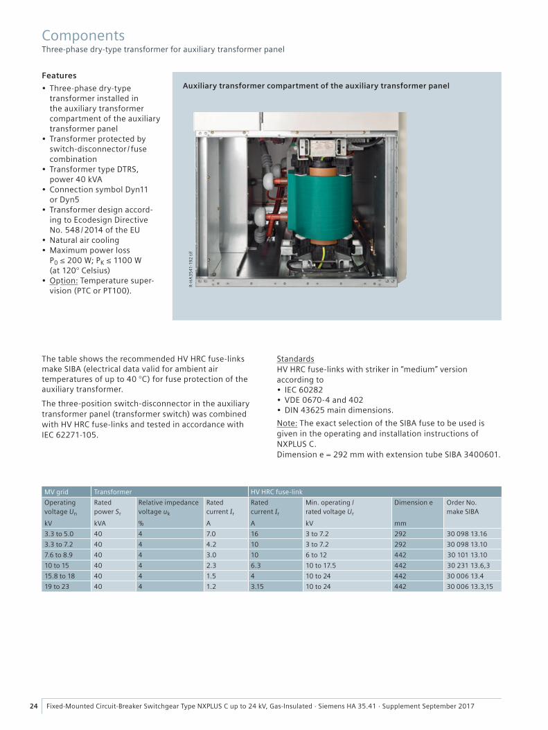
Features
• Three-phase dry-type transformer installed in the auxiliary transformer compartment of the auxiliary transformer panel
• Transformer protected by switch-disconnector / fuse combination
• Transformer type DTRS, power 40 kVA
• Connection symbol Dyn11 or Dyn5
• Transformer design accord-ing to Ecodesign Directive No. 548 / 2014 of the EU
• Natural air cooling• Maximum power loss
P0 ≤ 200 W; PK ≤ 1100 W(at 120° Celsius)
• Option: Temperature super-vision (PTC or PT100).
Auxiliary transformer compartment of the auxiliary transformer panel
The table shows the recommended HV HRC fuse-links make SIBA (electrical data valid for ambient air temperatures of up to 40 °C) for fuse protection of the auxiliary transformer.
The three-position switch-disconnector in the auxiliary transformer panel (transformer switch) was combined with HV HRC fuse-links and tested in accordance with IEC 62271-105.
StandardsHV HRC fuse-links with striker in “medium” version according to• IEC 60282• VDE 0670-4 and 402• DIN 43625 main dimensions.
Note: The exact selection of the SIBA fuse to be used is given in the operating and installation instructions of NXPLUS C.Dimension e = 292 mm with extension tube SIBA 3400601.
MV grid Transformer HV HRC fuse-link
Operating voltage Un
kV
Rated power Sr
kVA
Relative impedance voltage uk
%
Rated current Ir
A
Rated current Ir
A
Min. operating / rated voltage Ur
kV
Dimension e
mm
Order No. make SIBA
3.3 to 5.0 40 4 7.0 16 3 to 7.2 292 30 098 13.16
3.3 to 7.2 40 4 4.2 10 3 to 7.2 292 30 098 13.10
7.6 to 8.9 40 4 3.0 10 6 to 12 442 30 101 13.10
10 to 15 40 4 2.3 6.3 10 to 17.5 442 30 231 13.6,3
15.8 to 18 40 4 1.5 4 10 to 24 442 30 006 13.4
19 to 23 40 4 1.2 3.15 10 to 24 442 30 006 13.3,15
R-H
A3
541
-192
tif
�
��
� � �
���� ��� ��
����
����
���
�
��� ���
� � �
�
��
��� ���
� �
���
����
����
� �
� �
���
����
���
� �
HA
35-2
820
eps
4
�
���
����
���
� �
25Fixed-Mounted Circuit-Breaker Switchgear Type NXPLUS C up to 24 kV, Gas-Insulated · Siemens HA 35.41 · Supplement September 2017
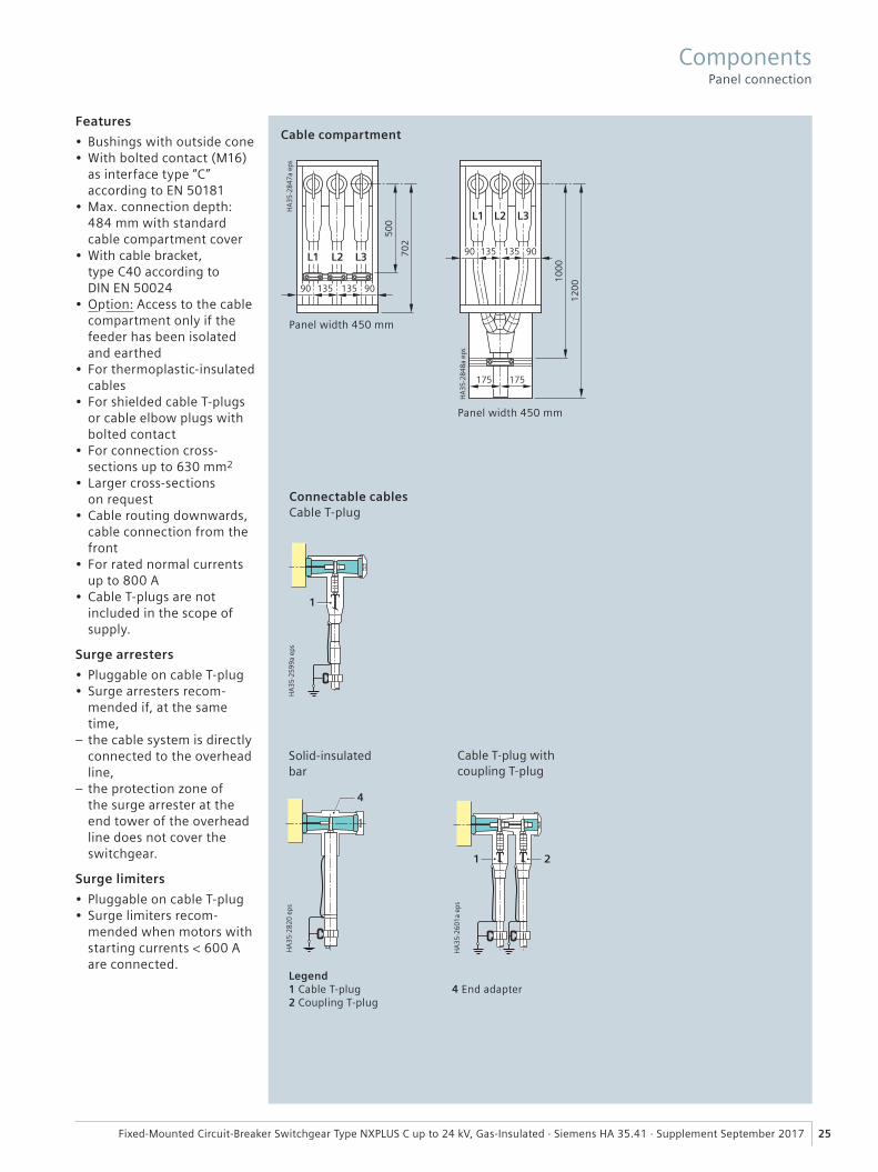
Features
• Bushings with outside cone• With bolted contact (M16)
as interface type “C” according to EN 50181
• Max. connection depth: 484 mm with standard cable compartment cover
• With cable bracket, type C40 according to DIN EN 50024
• Option: Access to the cable compartment only if the feeder has been isolated and earthed
• For thermoplastic-insulated cables
• For shielded cable T-plugs or cable elbow plugs with bolted contact
• For connection cross- sections up to 630 mm2
• Larger cross-sections on request
• Cable routing downwards, cable connection from the front
• For rated normal currentsup to 800 A
• Cable T-plugs are not included in the scope of supply.
Surge arresters
• Pluggable on cable T-plug• Surge arresters recom-
mended if, at the same time,
– the cable system is directly connected to the overhead line,
– the protection zone of the surge arrester at the end tower of the overhead line does not cover the switchgear.
Surge limiters
• Pluggable on cable T-plug• Surge limiters recom-
mended when motors with starting currents < 600 A are connected.
Connectable cablesCable T-plug
Cable T-plug with coupling T-plug
Cable compartment
Panel width 450 mm
Panel width 450 mm
Legend1 Cable T-plug2 Coupling T-plug
4 End adapter
Solid-insulated bar
Components Panel connection
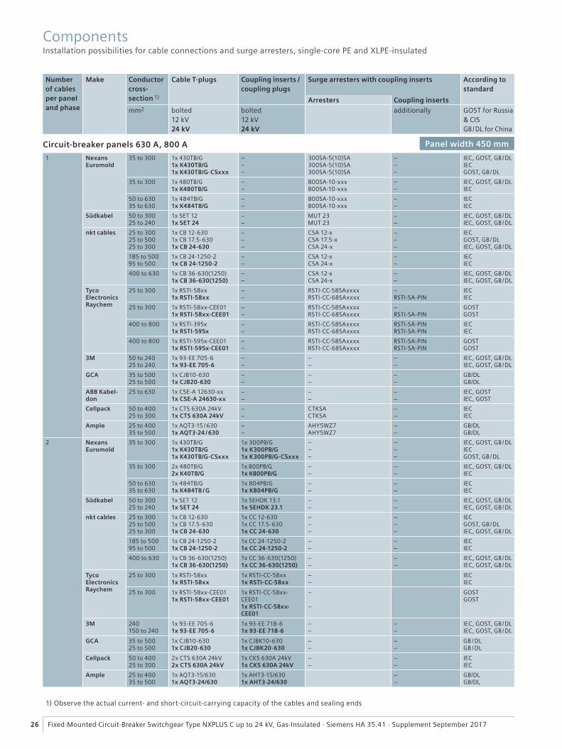
26 Fixed-Mounted Circuit-Breaker Switchgear Type NXPLUS C up to 24 kV, Gas-Insulated · Siemens HA 35.41 · Supplement September 2017
Numberof cablesper paneland phase
Make Conductor cross-section 1)
Cable T-plugs Coupling inserts /coupling plugs
Surge arresters with coupling inserts According to standard
Arresters Coupling inserts
mm2 bolted12 kV24 kV
bolted12 kV24 kV
additionally GOST for Russia & CISGB / DL for China
Circuit-breaker panels 630 A, 800 A Panel width 450 mm
1 Nexans Euromold
35 to 300 1x 430TB/G1x K430TB/G1x K430TB/G-CSxxx
–––
300SA-5(10)SA300SA-5(10)SA300SA-5(10)SA
–––
IEC, GOST, GB / DLIECGOST, GB / DL
35 to 300 1x 480TB/G1x K480TB/G
––
800SA-10-xxx800SA-10-xxx
––
IEC, GOST, GB / DLIEC
50 to 63035 to 630
1x 484TB/G1x K484TB/G
––
800SA-10-xxx800SA-10-xxx
––
IECIEC
Südkabel 50 to 30025 to 240
1x SET 121x SET 24
––
MUT 23MUT 23
––
IEC, GOST, GB / DLIEC, GOST, GB / DL
nkt cables 25 to 30025 to 50025 to 300
1x CB 12-6301x CB 17.5-6301x CB 24-630
–––
CSA 12-xCSA 17.5-xCSA 24-x
–––
IECGOST, GB / DLIEC, GOST, GB / DL
185 to 50095 to 500
1x CB 24-1250-21x CB 24-1250-2
––
CSA 12-xCSA 24-x
––
IECIEC
400 to 630 1x CB 36-630(1250)1x CB 36-630(1250)
––
CSA 12-xCSA 24-x
––
IEC, GOST, GB / DLIEC, GOST, GB / DL
Tyco ElectronicsRaychem
25 to 300 1x RSTI-58xx1x RSTI-58xx
––
RSTI-CC-58SAxxxxRSTI-CC-68SAxxxx
–RSTI-SA-PIN
IECIEC
25 to 300 1x RSTI-58xx-CEE011x RSTI-58xx-CEE01
––
RSTI-CC-58SAxxxxRSTI-CC-68SAxxxx
–RSTI-SA-PIN
GOSTGOST
400 to 800 1x RSTI-395x1x RSTI-595x
––
RSTI-CC-58SAxxxxRSTI-CC-68SAxxxx
RSTI-SA-PINRSTI-SA-PIN
IECIEC
400 to 800 1x RSTI-595x-CEE011x RSTI-595x-CEE01
––
RSTI-CC-58SAxxxxRSTI-CC-68SAxxxx
RSTI-SA-PINRSTI-SA-PIN
GOSTGOST
3M 50 to 24025 to 240
1x 93-EE 705-61x 93-EE 705-6
––
––
––
IEC, GOST, GB / DLIEC, GOST, GB / DL
GCA 35 to 50025 to 500
1x CJB10-6301x CJB20-630
––
––
––
GB/DLGB/DL
ABB Kabel-don
25 to 630 1x CSE-A 12630-xx1x CSE-A 24630-xx
––
––
––
IEC, GOSTIEC, GOST
Cellpack 50 to 40025 to 300
1x CTS 630A 24kV1x CTS 630A 24kV
––
CTKSACTKSA
––
IECIEC
Ample 25 to 40035 to 500
1x AQT3-15 / 6301x AQT3-24 / 630
––
AHY5WZ7AHY5WZ7
––
GB/DLGB/DL
2 NexansEuromold
35 to 300 1x 430TB/G1x K430TB/G1x K430TB/G-CSxxx
1x 300PB/G1x K300PB/G1x K300PB/G-CSxxx
–––
–––
IEC, GOST, GB / DLIECGOST, GB / DL
35 to 300 2x 480TB/G2x K40TB/G
1x 800PB/G1x K800PB/G
––
––
IEC, GOST, GB / DLIEC
50 to 63035 to 630
1x 484TB/G1x K484TB / G
1x 804PB/G1x K804PB/G
––
––
IECIEC
Südkabel 50 to 30025 to 240
1x SET 121x SET 24
1x SEHDK 13.11x SEHDK 23.1
––
––
IEC, GOST, GB / DLIEC, GOST, GB / DL
nkt cables 25 to 30025 to 50025 to 300
1x CB 12-6301x CB 17.5-6301x CB 24-630
1x CC 12-6301x CC 17.5-6301x CC 24-630
–––
–––
IECGOST, GB / DLIEC, GOST, GB / DL
185 to 50095 to 500
1x CB 24-1250-21x CB 24-1250-2
1x CC 24-1250-21x CC 24-1250-2
––
––
IECIEC
400 to 630 1x CB 36-630(1250)1x CB 36-630(1250)
1x CC 36-630(1250)1x CC 36-630(1250)
––
––
IEC, GOST, GB / DLIEC, GOST, GB / DL
Tyco ElectronicsRaychem
25 to 300 1x RSTI-58xx1x RSTI-58xx
1x RSTI-CC-58xx1x RSTI-CC-58xx
––
IECIEC
25 to 300 1x RSTI-58xx-CEE011x RSTI-58xx-CEE01
1x RSTI-CC-58xx-CEE011x RSTI-CC-58xx-CEE01
–
–
GOSTGOST
3M 240150 to 240
1x 93-EE 705-61x 93-EE 705-6
1x 93-EE 718-61x 93-EE 718-6
––
––
IEC, GOST, GB / DLIEC, GOST, GB / DL
GCA 35 to 50025 to 500
1x CJB10-6301x CJB20-630
1x CJBK10-6301x CJBK20-630
––
––
GB / DLGB / DL
Cellpack 50 to 40025 to 300
2x CTS 630A 24kV2x CTS 630A 24kV
1x CKS 630A 24kV1x CKS 630A 24kV
––
––
IECIEC
Ample 25 to 40035 to 500
1x AQT3-15/6301x AQT3-24/630
1x AHT3-15/6301x AHT3-24/630
––
GB/DLGB/DL
1) Observe the actual current- and short-circuit-carrying capacity of the cables and sealing ends
Components Installation possibilities for cable connections and surge arresters, single-core PE and XLPE-insulated
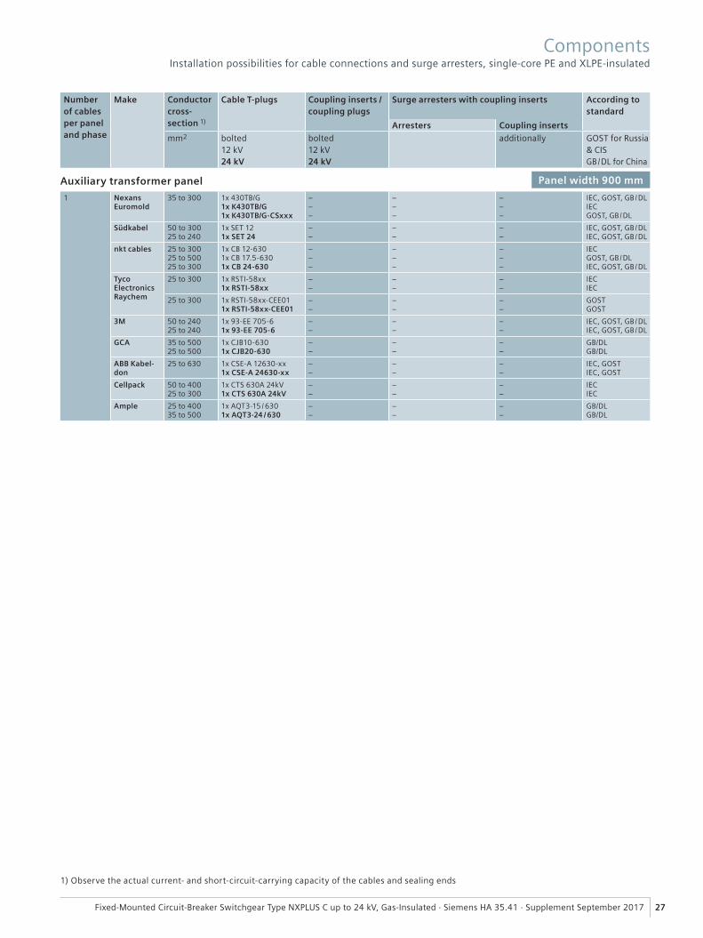
27Fixed-Mounted Circuit-Breaker Switchgear Type NXPLUS C up to 24 kV, Gas-Insulated · Siemens HA 35.41 · Supplement September 2017
1) Observe the actual current- and short-circuit-carrying capacity of the cables and sealing ends
ComponentsInstallation possibilities for cable connections and surge arresters, single-core PE and XLPE-insulated
Numberof cablesper paneland phase
Make Conductor cross-section 1)
Cable T-plugs Coupling inserts /coupling plugs
Surge arresters with coupling inserts According to standard
Arresters Coupling inserts
mm2 bolted12 kV24 kV
bolted12 kV24 kV
additionally GOST for Russia & CISGB / DL for China
Auxiliary transformer panel Panel width 900 mm
1 Nexans Euromold
35 to 300 1x 430TB/G1x K430TB/G1x K430TB/G-CSxxx
–––
–––
–––
IEC, GOST, GB / DLIECGOST, GB / DL
Südkabel 50 to 30025 to 240
1x SET 121x SET 24
––
––
––
IEC, GOST, GB / DLIEC, GOST, GB / DL
nkt cables 25 to 30025 to 50025 to 300
1x CB 12-6301x CB 17.5-6301x CB 24-630
–––
–––
–––
IECGOST, GB / DLIEC, GOST, GB / DL
Tyco ElectronicsRaychem
25 to 300 1x RSTI-58xx1x RSTI-58xx
––
––
––
IECIEC
25 to 300 1x RSTI-58xx-CEE011x RSTI-58xx-CEE01
––
––
––
GOSTGOST
3M 50 to 24025 to 240
1x 93-EE 705-61x 93-EE 705-6
––
––
––
IEC, GOST, GB / DLIEC, GOST, GB / DL
GCA 35 to 50025 to 500
1x CJB10-6301x CJB20-630
––
––
––
GB/DLGB/DL
ABB Kabel-don
25 to 630 1x CSE-A 12630-xx1x CSE-A 24630-xx
––
––
––
IEC, GOSTIEC, GOST
Cellpack 50 to 40025 to 300
1x CTS 630A 24kV1x CTS 630A 24kV
––
––
––
IECIEC
Ample 25 to 40035 to 500
1x AQT3-15 / 6301x AQT3-24 / 630
––
––
––
GB/DLGB/DL
�
��
�
���
����
��
� �
R-H
A3
541
-18
9 t
if
1
28 Fixed-Mounted Circuit-Breaker Switchgear Type NXPLUS C up to 24 kV, Gas-Insulated · Siemens HA 35.41 · Supplement September 2017
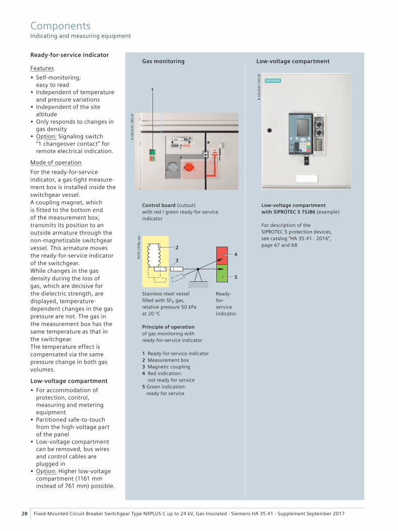
Gas monitoring Low-voltage compartmentReady-for-service indicator
Features
• Self-monitoring; easy to read
• Independent of temperature and pressure variations
• Independent of the site altitude
• Only responds to changes in gas density
• Option: Signaling switch “1 changeover contact” for remote electrical indication.
Mode of operation
For the ready-for-service indicator, a gas-tight measure-ment box is installed inside the switchgear vessel.A coupling magnet, which is fi tted to the bottom end of the measurement box, transmits its position to an outside armature through the non-magnetizable switchgear vessel. This armature moves the ready-for-service indicator of the switchgear. While changes in the gas density during the loss of gas, which are decisive for the dielectric strength, are displayed, temperature-dependent changes in the gas pressure are not. The gas in the measurement box has the same temperature as that in the switchgear.The temperature effect is compensated via the same pressure change in both gas volumes.
Low-voltage compartment
• For accommodation of protection, control, measuring and metering equipment
• Partitioned safe-to-touch from the high-voltage part of the panel
• Low-voltage compartment can be removed, bus wires and control cables are plugged in
• Option: Higher low-voltage compartment (1161 mm instead of 761 mm) possible.
Control board (cutout) with red / green ready-for-service indicator
Stainless-steel vesselfi lled with SF6 gas,relative pressure 50 kPa at 20 °C
Principle of operation of gas monitoring with ready-for-service indicator
1 Ready-for-service indicator2 Measurement box3 Magnetic coupling4 Red indication:
not ready for service5 Green indication:
ready for service
Ready-for-service indicator
Low-voltage compartment with SIPROTEC 5 7SJ86 (example)
For description of theSIPROTEC 5 protection devices, see catalog “HA 35.41 · 2016”, page 67 and 68
R-H
A3
541
-19
0 t
if
Components Indicating and measuring equipment
���
����
���
����
�
�����
��������������������
����
����
����
����
��������� ����� �����
����
�
����
����
���
���
����
!��
�
"�����������������#�$�������$��
29Fixed-Mounted Circuit-Breaker Switchgear Type NXPLUS C up to 24 kV, Gas-Insulated · Siemens HA 35.41 · Supplement September 2017
Overview of standards (September 2017)IEC standard VDE standard EN standard
Switchgear NXPLUS C IEC 62271-1 VDE 0671-1 EN 62271-1IEC 62271-200 VDE 0671-200 EN 62271-200IEC 62271-304 – eLC / TS 62271-304
Devices Circuit-breakers IEC 62271-100 VDE 0671-100 EN 62271-100
Vacuum contactors IEC 60470 VDE 0670-501 EN 60470Disconnectors and earthing switches IEC 62271-102 VDE 0671-102 EN 62271-102Switch-disconnectors IEC 62271-103 VDE 0671-103 EN 62271-103Switch-disconnector /fuse combination
IEC 62271-105 VDE 0671-105 EN 62271-105
HV HRC fuses IEC 60282 VDE 0670-4 EN 60282Voltage detecting systems IEC 61243-5 VDE 0682-415 EN 61243-5
Degree of protection IP code IEC 60529 VDE 0470-1 EN 60529IK code IEC 62262 VDE 0470-100 EN 50102
Insulation – IEC 60071 VDE 0111 EN 60071Instrument transformers – IEC 61869-1 VDE 0414-9-1 EN 61869-1
Current transformers IEC 61869-2 VDE 0414-9-2 EN 61869-2Voltage transformers IEC 61869-3 VDE 0414-9-3 EN 61869-3
Installation, erection – IEC 61936-1 VDE 0101 –
Insulating gas SF6 Specifi cation for new SF6 IEC 60376 VDE 0373-1 EN 60376
Type of service locationThe switchgear can be used as indoor installation accord-ing to IEC 61936 (Power installations exceeding AC 1 kV) and VDE 0101• outside lockable electrical service locations at places which
are not accessible to the public. Enclosures of switchgear can only be removed with tools
• in lockable electrical service locations. A lockable electrical service location is a place outdoors or indoors that is reserved exclusively for housing electrical equipment and which is kept under lock and key. Access is restricted to authorized personnel and persons who have been properly instructed in electrical engineering. Untrained or unskilled persons may only enter under the supervision of authorized personnel or properly instructed persons.
Terms“Make-proof earthing switches” are earthing switches with short-circuit making capacity according to IEC 62271-102 and VDE 0671-102 / EN 62271-102.
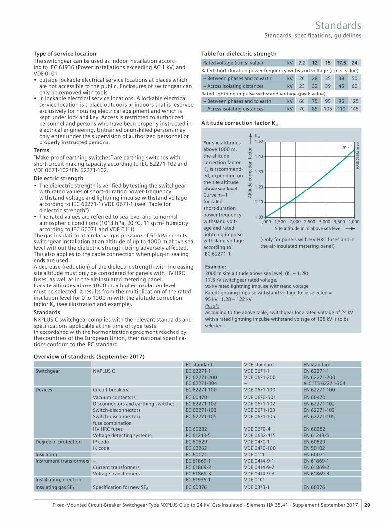
Dielectric strength• The dielectric strength is verifi ed by testing the switchgear
with rated values of short-duration power-frequency withstand voltage and lightning impulse withstand voltage according to IEC 62271-1/ VDE 0671-1 (see “Table for dielectric strength”).
• The rated values are referred to sea level and to normal atmospheric conditions (1013 hPa, 20 °C, 11 g /m3 humidity according to IEC 60071 and VDE 0111).
The gas insulation at a relative gas pressure of 50 kPa permits switchgear installation at an altitude of up to 4000 m above sea level without the dielectric strength being adversely affected. This also applies to the cable connection when plug-in sealing ends are used.A decrease (reduction) of the dielectric strength with increasing site altitude must only be considered for panels with HV HRC fuses, as well as in the air-insulated metering panel.For site altitudes above 1000 m, a higher insulation level must be selected. It results from the multiplication of the rated insulation level for 0 to 1000 m with the altitude correction factor Ka (see illustration and example).
Standards NXPLUS C switchgear complies with the relevant standards and specifi cations applicable at the time of type tests.In accordance with the harmonization agreement reached by the countries of the European Union, their national specifi ca-tions conform to the IEC standard.
Example:3000 m site altitude above sea level, (Ka = 1.28), 17.5 kV switchgear rated voltage, 95 kV rated lightning impulse withstand voltageRated lightning impulse withstand voltage to be selected = 95 kV · 1.28 = 122 kVResult:According to the above table, switchgear for a rated voltage of 24 kV with a rated lightning impulse withstand voltage of 125 kV is to be selected.
Table for dielectric strength
Rated voltage (r.m.s. value) kV 7.2 12 15 17.5 24
Rated short-duration power-frequency withstand voltage (r.m.s. value)
– Between phases and to earth kV 20 28 35 38 50
– Across isolating distances kV 23 32 39 45 60
Rated lightning impulse withstand voltage (peak value)
– Between phases and to earth kV 60 75 95 95 125
– Across isolating distances kV 70 85 105 110 145
For site altitudes above 1000 m, the altitude correction factor Ka is recommend-ed, depending on the site altitude above sea level.Curve m=1 for ratedshort-durationpower-frequency withstand volt-age and rated lightning impulse withstand voltage according toIEC 62271-1
(Only for panels with HV HRC fuses and in the air-insulated metering panel)
Altitude correction factor Ka
Standards Standards, specifi cations, guidelines
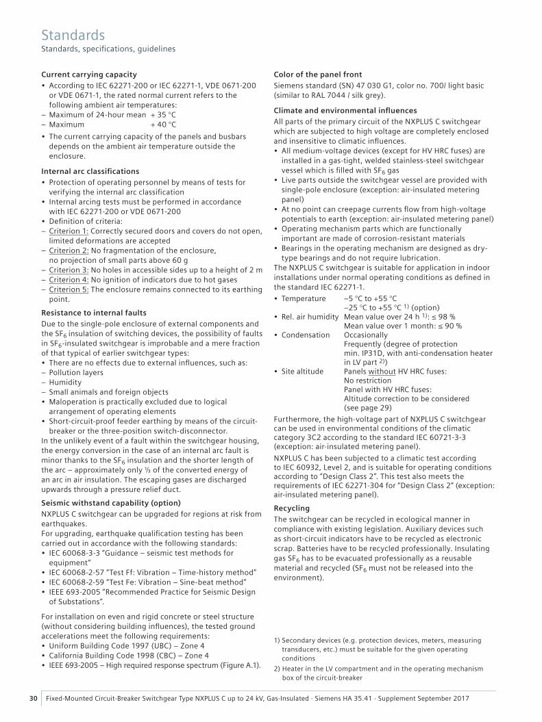
30 Fixed-Mounted Circuit-Breaker Switchgear Type NXPLUS C up to 24 kV, Gas-Insulated · Siemens HA 35.41 · Supplement September 2017
Current carrying capacity• According to IEC 62271-200 or IEC 62271-1, VDE 0671-200
or VDE 0671-1, the rated normal current refers to the following ambient air temperatures:
– Maximum of 24-hour mean + 35 °C – Maximum + 40 °C
• The current carrying capacity of the panels and busbars depends on the ambient air temperature outside the enclosure.
Internal arc classifi cations• Protection of operating personnel by means of tests for
verifying the internal arc classifi cation• Internal arcing tests must be performed in accordance
with IEC 62271-200 or VDE 0671-200 • Defi nition of criteria:
– Criterion 1: Correctly secured doors and covers do not open, limited deformations are accepted
– Criterion 2: No fragmentation of the enclosure, no projection of small parts above 60 g
– Criterion 3: No holes in accessible sides up to a height of 2 m – Criterion 4: No ignition of indicators due to hot gases – Criterion 5: The enclosure remains connected to its earthing point.
Resistance to internal faultsDue to the single-pole enclosure of external components and the SF6 insulation of switching devices, the possibility of faults in SF6-insulated switchgear is improbable and a mere fraction of that typical of earlier switchgear types:• There are no effects due to external infl uences, such as:
– Pollution layers – Humidity – Small animals and foreign objects
• Maloperation is practically excluded due to logical arrangement of operating elements
• Short-circuit-proof feeder earthing by means of the circuit-breaker or the three-position switch-disconnector.
In the unlikely event of a fault within the switchgear housing, the energy conversion in the case of an internal arc fault is minor thanks to the SF6 insulation and the shorter length of the arc – approximately only ⅓ of the converted energy of an arc in air insulation. The escaping gases are discharged upwards through a pressure relief duct.
Seismic withstand capability (option) NXPLUS C switchgear can be upgraded for regions at risk from earthquakes.For upgrading, earthquake qualifi cation testing has been carried out in accordance with the following standards:• IEC 60068-3-3 “Guidance – seismic test methods for
equipment”• IEC 60068-2-57 “Test Ff: Vibration – Time-history method”• IEC 60068-2-59 “Test Fe: Vibration – Sine-beat method”• IEEE 693-2005 “Recommended Practice for Seismic Design
of Substations”.
For installation on even and rigid concrete or steel structure (without considering building infl uences), the tested ground accelerations meet the following requirements:• Uniform Building Code 1997 (UBC) – Zone 4• California Building Code 1998 (CBC) – Zone 4• IEEE 693-2005 – High required response spectrum (Figure A.1).
Color of the panel frontSiemens standard (SN) 47 030 G1, color no. 700/ light basic(similar to RAL 7044 / silk grey).
Climate and environmental infl uencesAll parts of the primary circuit of the NXPLUS C switchgear which are subjected to high voltage are completely enclosed and insensitive to climatic infl uences.• All medium-voltage devices (except for HV HRC fuses) are
installed in a gas-tight, welded stainless-steel switchgear vessel which is fi lled with SF6 gas
• Live parts outside the switchgear vessel are provided with single-pole enclosure (exception: air-insulated metering panel)
• At no point can creepage currents fl ow from high-voltage potentials to earth (exception: air-insulated metering panel)
• Operating mechanism parts which are functionally important are made of corrosion-resistant materials
• Bearings in the operating mechanism are designed as dry-type bearings and do not require lubrication.
The NXPLUS C switchgear is suitable for application in indoor installations under normal operating conditions as defi ned in the standard IEC 62271-1.
• Temperature –5 °C to +55 °C –25 °C to +55 °C 1) (option)
• Rel. air humidity Mean value over 24 h 1): ≤ 98 % Mean value over 1 month: ≤ 90 %
• Condensation OccasionallyFrequently (degree of protection min. IP31D, with anti-condensation heater in LV part 2))
• Site altitude Panels without HV HRC fuses: No restriction Panel with HV HRC fuses: Altitude correction to be considered (see page 29)
Furthermore, the high-voltage part of NXPLUS C switchgear can be used in environmental conditions of the climatic category 3C2 according to the standard IEC 60721-3-3 (exception: air-insulated metering panel).
NXPLUS C has been subjected to a climatic test according to IEC 60932, Level 2, and is suitable for operating conditions according to “Design Class 2”. This test also meets the requirements of IEC 62271-304 for “Design Class 2” (exception: air-insulated metering panel).
RecyclingThe switchgear can be recycled in ecological manner in compliance with existing legislation. Auxiliary devices such as short-circuit indicators have to be recycled as electronic scrap. Batteries have to be recycled professionally. Insulating gas SF6 has to be evacuated professionally as a reusable material and recycled (SF6 must not be released into the environment).
1) Secondary devices (e.g. protection devices, meters, measuring transducers, etc.) must be suitable for the given operating conditions
2) Heater in the LV compartment and in the operating mechanism box of the circuit-breaker
StandardsStandards, specifi cations, guidelines
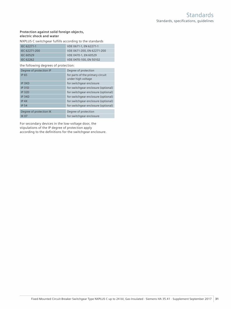
31Fixed-Mounted Circuit-Breaker Switchgear Type NXPLUS C up to 24 kV, Gas-Insulated · Siemens HA 35.41 · Supplement September 2017
Protection against solid foreign objects, electric shock and water
NXPLUS C switchgear fulfi lls according to the standards
IEC 62271-1 VDE 0671-1, EN 62271-1
IEC 62271-200 VDE 0671-200, EN 62271-200
IEC 60529 VDE 0470-1, EN 60529
IEC 62262 VDE 0470-100, EN 50102
the following degrees of protection:
Degree of protection IP Degree of protection
IP 65 for parts of the primary circuit under high voltage
IP 3XD for switchgear enclosure
IP 31D for switchgear enclosure (optional)
IP 32D for switchgear enclosure (optional)
IP 34D for switchgear enclosure (optional)
IP 4X for switchgear enclosure (optional)
IP 54 for switchgear enclosure (optional)
Degree of protection IK Degree of protection
IK 07 for switchgear enclosure
For secondary devices in the low-voltage door, the stipulations of the IP degree of protection apply according to the defi nitions for the switchgear enclosure.
StandardsStandards, specifi cations, guidelines
Supplement September 2017
Published bySiemens AG 2017
Energy ManagementMedium Voltage & SystemsMozartstraße 31 C91052 Erlangen, Germany
For further information, please contactour Customer Support Center:Phone: +49 180 524 70 00Fax: +49 180 524 24 71E-mail: [email protected]/medium-voltage-switchgearsiemens.com/NXPLUSC-SBBsiemens.com/NXPLUSC-DBB
Article No. EMMS-K1435-E401-A3-7600Printed in GermanyKG 9.17 2.0 32 En | BG184 / 1780
Subject to changes and errors. The information given in this document only contains general descriptions and/or performance features which may not always specifically reflect those described, or which may undergo modification in the course of further development of the products. The requested performance features are binding only when they are expressly agreed upon in the con-cluded contract.
Top Related