


Languages
Pages
Legal


FISICA Deliverable D1.2
Far Infra-red Space Interferometer Critical Assessment
PU 1 v1.0
FISICA
Far Infra-red Space Interferometer Critical Assessment Deliverable D1.2
Grant agreement no. 312818
SPA.2012.2.2-01: Key technologies enabling observations in and from space
- Collaborative project -
D1.2 Instrument performance requirements preliminary
document WP 1 - Scientific definition of Instrument Requirements
Due date of deliverable: Month 25 Actual submission date: Start date of project: January 1st 2013 Duration: 36 months
Lead beneficiary for this deliverable: Science and Technology Facilities Council (STFC), UK Lead author: Wayne Holland, UK ATC (STFC)/University of Edinburgh Contributing authors: Giorgio Savini (UCL), Créidhe O’Sullivan (NUIM), Enzo Pascale (Cardiff), David Naylor
(Lethbridge), Brad Gom (Lethbridge), Luigi Spinoglio (INAF), Kjetil Dohlen (LAM)
Project co-funded by the European Union’s Seventh Framework Programme for research, technological development and demonstration
Dissemination Level
PU Public
PP Restricted to other programme participants (including the Commission Services)
RE Restricted to a group specified by the consortium (including the Commission Services)
CO Confidential, only for members of the consortium (including the Commission Services)

FISICA Deliverable D1.2
Far Infra-red Space Interferometer Critical Assessment
PU 2 v1.0
FISICA Deliverable D1.2
Far Infra-red Space Interferometer Critical Assessment
PU 3 v1.0
Summary This document presents the design requirements for the next generation far-infrared space
interferometer (FIRI) that will allow such a mission to achieve its scientific goals. Starting from the
science case (outlined in submitted FISICA report D1.1) a preliminary set of requirements for the
telescope/instrument are derived. These include a series of “top-level” conditions based on the need
to carry out ultra-sensitive observations at high angular resolution in the far-infrared region of the
electromagnetic spectrum. Further to this, requirements are generated for both the telescope system
and the instrument (contained within the “hub” of the satellite). Calculations, based on a current
“Strawman” model of the telescope/instrument have been performed to estimate achievable
sensitivities, which in turn place stringent demands on the detector arrays. Finally, preliminary
operational requirements are also discussed, particularly those that have a potential impact on
instrument performance. It should be emphasised that this document represents an interim report on
the identified preliminary requirements, largely as a result of the science case, and future/ongoing
work in specific areas is highlighted. A final document, which will consolidate and expand upon the
work presented here and in other work-packages, will be submitted at the end of the project.
History table
Version Date Released by Comments
0.1 05/12/2014 Wayne Holland Draft for comment
0.2 19/1/2015 Wayne Holland Second complete draft
1.0 25/1/2015 Wayne Holland Final version

FISICA Deliverable D1.2
Far Infra-red Space Interferometer Critical Assessment
PU 4 v1.0
Table of Contents Summary .......................................................................................................................................................... 3
History table ..................................................................................................................................................... 3
Key word list .................................................................................................................................................... 6
Definitions and acronyms .............................................................................................................................. 6
Acknowledgements ........................................................................................................................................ 6
Disclaimer ........................................................................................................................................................ 6
1. Introduction .............................................................................................................................................. 7
1.1 Science drivers ..................................................................................................................................... 7
1.2 Science requirements .......................................................................................................................... 7
2. Top-level requirements .......................................................................................................................... 8
2.1 Wavelength range ................................................................................................................................ 8
2.2 Angular resolution ................................................................................................................................ 9
2.3 Spectral resolution ............................................................................................................................. 10
2.4 Sensitivity ............................................................................................................................................ 10
2.5 Field-of-view ........................................................................................................................................ 11
3. Telescope requirements ...................................................................................................................... 11
3.1 Collecting area of the primary .......................................................................................................... 11
3.2 Optical configuration .......................................................................................................................... 11
3.2.1 FIRI-type design .................................................................................................................... 12
3.2.2 BETTII-type design ............................................................................................................... 12
3.3 Image quality ....................................................................................................................................... 13
3.4 Thermal considerations and stray light ........................................................................................... 14
3.5 Pointing accuracy ............................................................................................................................... 15
4. Instrument requirements ...................................................................................................................... 17
4.1 Cryostat and cooling systems .......................................................................................................... 17
4.2 Delay line and re-imaging optics ................................................................................................ 20
4.3 Filtering and dichroic .......................................................................................................................... 20
4.4 Beam combiner .................................................................................................................................. 21
4.5 Cold stop and baffling ........................................................................................................................ 21
4.6 Detector arrays ................................................................................................................................... 22
4.7 Electronics/signal readout requirements ........................................................................................ 24
5. Operational requirements .................................................................................................................... 25

FISICA Deliverable D1.2
Far Infra-red Space Interferometer Critical Assessment
PU 5 v1.0
5.1 Observing modes ............................................................................................................................... 25
5.2 Calibration ........................................................................................................................................... 26
5.3 Sky coverage ...................................................................................................................................... 26
5.4 Time to acquire an object .................................................................................................................. 26
5.5 Metrology ............................................................................................................................................. 27
5.5 Mission lifetime ................................................................................................................................... 27
References ..................................................................................................................................................... 28
Appendices .................................................................................................................................................... 28

FISICA Deliverable D1.2
Far Infra-red Space Interferometer Critical Assessment
PU 6 v1.0
Key word list
Instrumentation: high angular resolution
Instrumentation: interferometers
Instrumentation: spectrographs
Instrumentation: detector arrays
Techniques: high angular resolution
Techniques: imaging spectroscopy
Definitions and acronyms
ALMA Atacama Large Millimeter/Submillimeter Array
APE Absolute Pointing Error
BETTII Balloon Experimental Twin Telescope for Infrared Interferometry
JWST James Web Space Telescope
PSF Point-spread function
SCUBA-2 Submillimetre Common-User Bolometer Array
SPECS Submillimeter Probe of the Evolution of Cosmic Structure
SPIRE Spectral and Photometric Imaging Receiver
SPIRIT Space Infrared Interferometric Telescope
Acknowledgements The research leading to this report has received funding from the European Union’s Seventh
Framework Programme for research, technology development and demonstration under Grant
Agreement no. 312818 – FISICA.
Disclaimer The content of this deliverable does not reflect the official opinion of the European Union.
Responsibility for the information and views expressed in the deliverable therein lies with the
authors.

FISICA Deliverable D1.2
Far Infra-red Space Interferometer Critical Assessment
PU 7 v1.0
1. Introduction
1.1 Science drivers
The far-infrared region, which encompasses the spectral range from 30 to 300µm, contains a wealth
of information about the cold Universe. Observations of gas and dust probe the earliest stages in the
formation of galaxies, stars and planets. The recent success of the Herschel Space Observatory has
highlighted the importance of studying astrophysics in the far-IR region. However, the limited
angular resolution afforded by Herschel mean that the study of some of the most critical
astrophysical phenomena, which are often found on small size-scales, remains elusive. The FIRI
concept was proposed to fill the “resolution gap” by providing detail on sub-arcsecond scales in the
far-IR, as a complement, for example, to the James Webb Space telescope (JWST) at shorter
wavelengths (near IR) and the Atacama Large Millimeter/Submillimeter Array (ALMA) at longer
(300µm onwards).
The primary goal of such a mission is thus to carry out ultra-sensitive observations at high angular
resolution in the far-infrared region of the electromagnetic spectrum. The science case has been put
together based on a mission that will achieve the following three main goals:
1. That will operate in the far-infrared region of the spectrum addressing a number of key
scientific objectives, hitherto unanswered;
2. Will have the sensitivity and resolving power to measure a number of key ionic, atomic and
molecular lines over a range of astrophysical phenomena;
3. Has sufficient angular resolution to be able to probe the previously unexplored inner regions
of astrophysical phenomena, e.g. nuclei of galaxies, circumstellar disks and star-forming
cores.
1.2 Science requirements
The science requirements for a FIRI mission have been studied in detail in the first year of the
FISICA project. This culminated in a highly successful workshop, held in Rome in February 2014,
and the subsequent publication of a report on “Definition/update of key science questions and
relevant data products” (project deliverable D1.1; main author: Luigi Spinoglio). A number of key
scientific themes have been identified each of which has one or more relevant science cases. An
assessment was made on each in terms of the requirement on instrument sensitivity, angular-
resolution, field-of-view and spectral resolution. These are summarised in Table 1 in terms of the
requirements for medium resolution spectroscopy.
Theme Science Case Required field-of-view
(arcmin)
Required angular resolution
(arcsec)
Required spectral
resolution
Sensitivity required
(estimated line flux)
Star formation: Protostars
Resolve 100AU: detection of the first hydrostatic cores
0.5 – 1
0.25" @ 400pc
0.40" @ 250pc
0.66" @ 150pc
~3000
H2O: 2.1 10-20 W/m2
H2O: 5.4 10-20
H2O: 1.5 10-19
Star formation: Protoplanetary disks/Formation of planetary systems
Resolve the outer structure (10 – 100AU) of protoplanetary disks
1 – 2 0.20"
(30AU @ 140pc)
0.75"
(100AU @ 140pc)
~5000
A: [OI]63µm: 2.4 10-16
[OI]145µm: 1.2 10-17
B: [OI]63µm: 3.7 10-16
[OI]145µm: 3.1 10-17

FISICA Deliverable D1.2
Far Infra-red Space Interferometer Critical Assessment
PU 8 v1.0
Star formation: Binary and multiple systems
Resolve binary and multiple protostellar objects
0.5 0.25" @ 400pc ~3000
[OI]63µm: 9 10-19
H2O: 8 10-19 – 4 10-18
CO: 2 10-19 – 4 10-18
HDO: 4 10-18
Star formation: Massive star formation
Answer to the question if massive clumps form only one massive star or stellar clusters
1 – 2+ 0.25" @3kpc ~3000
12CO(10-9): 5 10-18 13CO(10-9): 8 10-19
C18O(10-9): 1 10-19
The Galactic Center
Map the central thousands AU around the SgrA* Black Hole in extinction free continuum and lines
1 – 2+ 0.25" @ 8kpc ~3000
[OI]63µm: 2.4 10-17
CO(14-13)@186µm:
1.9 10-19
CO(24-23)@108µm:
2.0 10-20
AGN in the local Universe
Resolving the torus and the emission-line regions in the circumnuclear environment of local AGN
0.5 – 1
0.10" @ 50Mpc 1500 – 3000
[OIV]26µm:
1 10-19, 1 10-18,
3 10-18 (min, ave, max) [NeV]24µm:
3 10-20, 2.8 10-19,
9 10-19 [OI]63µm:
6 10-19, 2.6 10-18,
7.6 10-18 Galaxy formation and Evolution
Resolving starburst complexes and Narrow Line Regions along galaxy evolution
1 – 2
0.10" starburst
(0.02" NLR)
1500 – 3000
Line fluxes are typically in the range 10-21 – 10-19
Table 1: Summary of the main requirements for each science theme in terms of medium resolution spectroscopy
2. Top-level requirements As outlined in section 1.2 the key drivers for a FIRI mission will be to carry out moderately-sized
field imaging, with medium spectral, and high angular resolution to great depth in the far-infrared.
FIRI will seek to maximise these capabilities within the constraints of a practical system. The
science requirements dictate a number of key top-level requirements which are now discussed.
2.1 Wavelength range
To achieve the science goals requires a continual spectral coverage between 25 and 400µm. The
vast majority of this wavelength range is inaccessible from the ground, necessitating a space-borne
mission. To optimise performance it will be necessary to split such a wide spectral range into
multiple bands, each of which, for example, will have its own optimised camera. The proposed
bands are listed in Table 2.
Band Central wavelength
(µm)
Lower-edge cut-off (µm)
Higher-edge cut-off (µm)
1 37.5 25 50
2 75 50 100
3 150 100 200
4 300 200 400

FISICA Deliverable D1.2
Far Infra-red Space Interferometer Critical Assessment
PU 9 v1.0
Table 2: Proposed bands for the instrument
R2.1.1. The continuous spectral coverage for the instrument will be from 25 to 400µm.
R2.1.2. Over the spectral range there will be 4 discrete bands, each of which will be optimised with
its own camera.
R2.1.3. Band 1 will be centered at 37.5µm and have low and high wavelength cut-offs at 25 and
50µm, respectively.
R2.1.4. Band 2 will be centered at 75µm and have low and high wavelength cut-offs at 50 and
100µm, respectively.
R2.1.5. Band 3 will be centered at 150µm and have low and high wavelength cut-offs at 100 and
200µm, respectively.
R2.1.6. Band 4 will be centered at 300µm and have low and high wavelength cut-offs at 200 and
400µm, respectively.
The baseline instrument currently has the aforementioned 4 observing bands by default. It is
possible that future iterations of the instrument may consolidate the spectral range, say from 30 to
300µm. This largely depends on factors such as whether overlap with ground-based facilities (such
as ALMA at 350µm) would be beneficial. For example, an instrument working over the range from
30 to 300µm could, in principle be covered with high efficiency using only 3 bands.
2.2 Angular resolution
The science requirements point to the need to spatially resolve astronomical objects with angular
sizes in the range 0.1 – 0.7 arcsecs. In particular, a key requirement for several of the science cases
is to achieve a resolution of 0.1 arcsec at a wavelength of 40µm. Since this requires a telescope
aperture of around 100m, an interferometer arrangement with 2 telescopes is the only realistic
option. Within the FISICA study 3 options are being considered with a maximum inter-telescope
baseline of 100m:
1. A tether connection between the 2 telescopes;
2. A rigid structure (boom) connecting the 2 telescopes;
3. A free-flying configuration.
The pros and cons of these options are subject to a separate design report (D1.3). For the baseline
FIRI design there will be 2 telescopes, nominally connected on a rigid boom, performing aperture
synthesis interferometry to achieve the required angular resolution.
R2.2.1. The minimum angular resolution achievable will be 0.1 arcsec at a wavelength of 40µm.
R2.2.2. The baseline will be variable from a few metres up to a maximum inter-telescope distance
of 100m.

FISICA Deliverable D1.2
Far Infra-red Space Interferometer Critical Assessment
PU 10 v1.0
2.3 Spectral resolution
The science drivers require the ability to perform imaging medium-resolution spectroscopy (R ~
1000 – 5000) as the key types of observations. This will allow ionic, atomic and molecular lines to
be observed within the spectral range of the instrument.
R2.3.1. In “spectroscopy mode” the resolving power required will be in the range 1000 – 5000.
Although the aforementioned “spectroscopy mode” is key to the achieving many of the science
requirements, the instrument should also not preclude complementary lower resolution
spectroscopy (R ~ 100) and even a spectrophotometry (R ~ 5) mode. For example, a mode with R ~
100 would be well-suited to measure the spectral energy distribution of objects within the
wavebands.
R2.3.2. In “SED mode” the resolving power required will be around 100.
Finally, a spectrophotometry capability should be available (R ~ 5). This will not only give crucial
information on the small and large-scale dust distribution but will also provide the ultimate
sensitivity on faint objects with wide spectral features, including galaxies, dust grains, and planetary
atmospheres.
R2.3.3. For “spectrophotometry mode” a spectral resolving power of ~5 is needed.
To achieve the range of spectral resolution needed it is proposed that a double Fourier spectro-
imaging technique be adopted.
2.4 Sensitivity
Typical line fluxes are in the range a few 10-16 to 10-19 W/m2, and so the requirement for the
sensitivity will be to reach the faintest levels of 10-19 W/m2 in 1 hour of observing time (1σ). The
goal is to improve on this by an order of magnitude i.e. achieve a level of 10-20 W/m2 (1σ in 1hr, or
5σ in 24 hrs).
R2.4.1. The requirement for the line sensitivity is 10-19 W/m2 (1σ in 1hr), with a goal of ~10-20
W/m2 (1σ in 1hr, or 5σ in 24 hrs).
For operating in spectrophotometry mode typical fluxes are in the mJy to few 10µJy range and so
the requirement is to be able to measure point-source fluxes to 30 µJy with a goal of again
improving upon this by an order of magnitude.
R2.4.2. The point-source sensitivity is required to measure flux density levels of 30µJy (1σ in 1hr,
or 5σ in 24 hrs) with a goal of <10µJy (1σ in 1hr, or 5σ in 24 hrs).
These are challenging levels to reach and will require careful consideration of the mission design,
including not only the collecting area of the telescope but the thermal design of the system to keep
background power to a minimum to avoid degrading sensitivity. To assist in this exercise Appendix
A1 summarises the rationale (and current performance estimates) behind the “FISICA Strawman
sensitivity model” which is being used to determine whether these sensitivity levels are feasible,
particularly in view of an evolving instrument design.

FISICA Deliverable D1.2
Far Infra-red Space Interferometer Critical Assessment
PU 11 v1.0
2.5 Field-of-view
The requirements for the field-of-view, for the majority of the science cases, are satisfied by a field
of 1 arcmin in diameter (assumed square) at the diffraction limit of the telescope. However, there
are some cases for which a larger field would be highly beneficial (e.g. following up on deep
“blank” surveys and the study of molecular clouds in nearby galaxies). For surveys of unresolved
point sources with a Nyquist-sampled telescope, the performance metric is D2Npix, where D is the
telescope diameter and Npix is the number of detector pixels, so there is a clear motivation for
having a larger field. Hence, there will be a goal of having a 2 arcmin diameter field for FIRI, and
the optical design will take this into account if possible.
R2.5.1. The field-of-view of the instrument will be 1 arcmin in diameter with a goal of 2 arcmins.
3. Telescope requirements The requirement for angular resolution in the typical range 0.1 – 0.7 arcsec, and crucially achieving
0.1 arcsec at 40µm, dictates that the telescope will be an interferometer with variable baseline of up
to 100m. The default design is currently for a 2 telescope system performing aperture synthesis
interferometry. The requirements of the telescopes and optical configuration to relay the beam to
the instrument hub beam combiner will now be considered.
3.1 Collecting area of the primary
Ideally, the collecting area of the primary should be as large as possible to maximise sensitivity.
However, practical limitations (e.g. size for launch, mass, manufacturability, cooling and pointing
tolerances) dictate a compromise in terms of diameter. Based on modelling (predictions of
achievable sensitivity – see Appendix A1), and taking into account practical sizes, the diameter of
the primary mirrors should be of order 2m.
R3.1.1. The primary mirrors of the telescope will be 2m in diameter.
A number of factors can degrade sensitivity (aberrations and surface errors) causing a loss of
throughput (see section 3.3) or distort the optical beam leading to poorer-than-expected image
quality. In addition, diffuse stray light from the telescope and sun-shield will degrade sensitivity by
adding noise to the observations (section 3.4).
3.2 Optical configuration
The optical configuration for each telescope has to ensure that the light collected from the sky is
relayed to the instrument hub, beam combiner and the detector arrays. This has to be done taking
into account the physical size of the relay optics (and subsequent hub optical components), whilst
minimising beam truncation and aberrations across the field. Aberrations will be considered further
in section 3.3.
One of the key consequences of the telescope optical configuration is the bearing on the diameter of
the cryostat window, subsequent optics and cold stop. The cryostat window should be kept small to
minimise background loading on the arrays and stray light, but accepting that a large de-
magnification factor from the telescope may introduce an unacceptable level of aberrations. A
practical upper limit for the size of the window and cold optics is 200mm.
R3.2.1 The instrument cryostat window and cold optics will not exceed 200mm in diameter.

FISICA Deliverable D1.2
Far Infra-red Space Interferometer Critical Assessment
PU 12 v1.0
Initial design work on the optical configuration was based on the original FIRI layout, having a 2m
diameter aperture stop at the primary mirror. The result of this, the cryostat window and subsequent
hub optics required were very large (approaching 0.5m for the latter). As an alternative, designs that
adopted compression (de-magnification) of the beam to reduce the size of the window and cold
optics were investigated:
1. Condensing optics at the primary element followed by a flat to direct the beam to the hub
(referred to as the "FIRI‐type");
2. A flat primary mirror (siderostat) with condensing optics near the hub (referred to as the
"BETTII‐type").
These will now be considered in turn.
3.2.1 FIRI-type design
The FIRI-type design incorporates an off-axis Cassegrain telescope together with an afocal beam
condenser arrangement as shown in Figure 1. Placing the aperture stop at the cryostat window
minimises its size but at the expense of needing a larger primary mirror (where the input beams no
longer overlap). The cryostat window size then just depends on the de-magnification chosen.
Figure 1: Optical configuration for the “FIRI-type” design.
In the example in Figure 1 the diameter of the primary mirror needed to keep the cryostat window
to 200mm with a de-magnification of 10 is ~3.5m. Hence, this configuration requires one (very)
large component (the primary) but more modestly-sized relay optics.
3.2.2 BETTII-type design
An alternative configuration is based on the design being built for BETTII as shown in Figure 2. In
this arrangement a flat siderostat relays the beam to an afocal telescope placed close to the hub. The
FISICA Deliverable D1.2
Far Infra-red Space Interferometer Critical Assessment
PU 13 v1.0
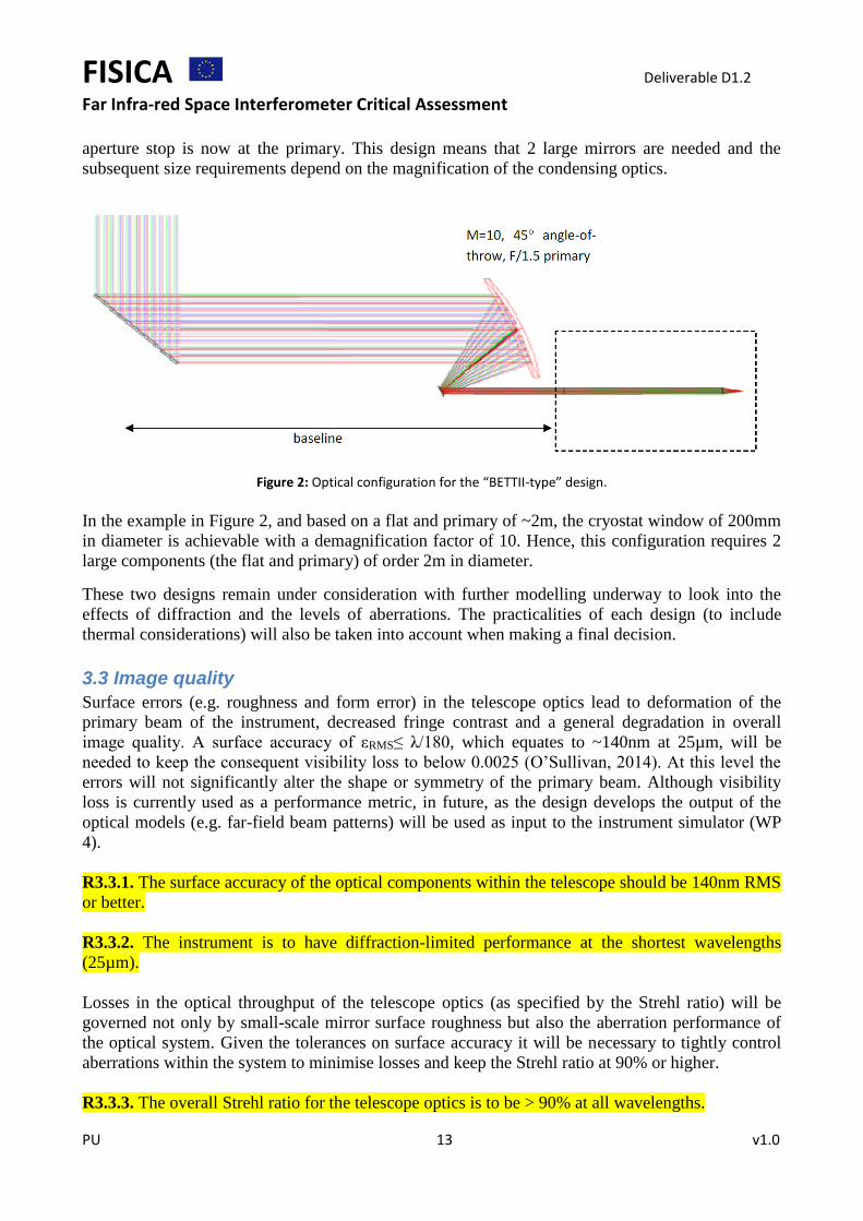
aperture stop is now at the primary. This design means that 2 large mirrors are needed and the
subsequent size requirements depend on the magnification of the condensing optics.
Figure 2: Optical configuration for the “BETTII-type” design.
In the example in Figure 2, and based on a flat and primary of ~2m, the cryostat window of 200mm
in diameter is achievable with a demagnification factor of 10. Hence, this configuration requires 2
large components (the flat and primary) of order 2m in diameter.
These two designs remain under consideration with further modelling underway to look into the
effects of diffraction and the levels of aberrations. The practicalities of each design (to include
thermal considerations) will also be taken into account when making a final decision.
3.3 Image quality
Surface errors (e.g. roughness and form error) in the telescope optics lead to deformation of the
primary beam of the instrument, decreased fringe contrast and a general degradation in overall
image quality. A surface accuracy of εRMS≤ λ/180, which equates to ~140nm at 25µm, will be
needed to keep the consequent visibility loss to below 0.0025 (O’Sullivan, 2014). At this level the
errors will not significantly alter the shape or symmetry of the primary beam. Although visibility
loss is currently used as a performance metric, in future, as the design develops the output of the
optical models (e.g. far-field beam patterns) will be used as input to the instrument simulator (WP
4).
R3.3.1. The surface accuracy of the optical components within the telescope should be 140nm RMS
or better.
R3.3.2. The instrument is to have diffraction-limited performance at the shortest wavelengths
(25µm).
Losses in the optical throughput of the telescope optics (as specified by the Strehl ratio) will be
governed not only by small-scale mirror surface roughness but also the aberration performance of
the optical system. Given the tolerances on surface accuracy it will be necessary to tightly control
aberrations within the system to minimise losses and keep the Strehl ratio at 90% or higher.
R3.3.3. The overall Strehl ratio for the telescope optics is to be > 90% at all wavelengths.

FISICA Deliverable D1.2
Far Infra-red Space Interferometer Critical Assessment
PU 14 v1.0
Another key issue for the optical design is to minimise field distortion (field dependent
magnification) across the focal plane of the detector array (particularly near the edges). These need
to be at such a level that one part of the array does not have a significantly worse point PSF than
any other. Field distortion should never be sufficient to mean that when performing an observation
one part of the array is left less than critically sampled. This criterion requires that field distortion at
the shortest wavelengths is less than 3% across the detector arrays.
R3.3.4. Field distortion across the detector arrays is required to be < 3%.
Further work:
1. Requirements (science-driven) for the maximum amplitude of near and far side-lobes
(“error beam”).
2. The maximum level of cross polarisation allowed.
3.4 Thermal considerations and stray light
The telescope components need to contribute as little as possible to the error budget for the
background photon noise, which in turn should ideally set the limit for the overall instrument
sensitivity. Figure 3 shows the contribution of photon noise from the telescope mirrors as a fraction
of the total background NEP as a function of mirror temperature. This was derived from the
sensitivity model (see Appendix A1). As can be seen the telescope mirror temperature is crucial at
the longer wavebands, and needs to be 4.5K or less to contribute 50% of the background power at
band 4.
Figure 3: The contribution of photon noise from the telescope as a fractional of the overall background NEP as a function of telescope temperature. This assumes any subsequent optics has a negligible contribution to the
background.
FISICA Deliverable D1.2
Far Infra-red Space Interferometer Critical Assessment
PU 15 v1.0
R3.4.1. The temperature of the mirrors in the telescope will be 4.5K or less.
This also assumes that the mirrors in the telescope have low emissivity values of 3% or less at all
wavebands.
R3.4.2. The emissivity of each telescope mirror will be < 3% at all wavelengths.
Understanding and controlling stray light to low levels is an essential requirement for success in the
deep exposures planned for FIRI. Diffuse stray light limits sensitivity by adding noise to the
observations. The diffuse stray light from the telescope and sunshield must contribute negligible
amounts to the overall background power budget. These levels can be determined by modelling
leading to enhancements in the design as needed (e.g. provision of baffles etc.). This also applies to
potential stray light sources within the instrument.
R3.4.3. Diffuse stray light will contribute less than 5% to the overall background power levels.
Local stray light sources (i.e. within the field-of-view) can produce ghost images and ultimately
limit image quality and the dynamic range of an observation. It should be the case that no more than
2% of the light from point sources will appear in the form of stray light or ghosts in the focal plane.
R3.4.4. A point source within the field-of-view will contribute < 2% of the light that appears as a
ghost image.
3.5 Pointing accuracy
The overall instrument (including telescope) needs several highly accurate metrology sub-systems.
Knowledge of the origin and propagation of phase and positional errors along the optical path is
critical to fringe visibility and interferogram reconstruction. Further discussion is given in section
5.4, and it is clear that minimising these errors will be a major operational challenge.
The requirements for the pointing and tracking (drift) accuracy depend on the science aims,
observing efficiency desired and the ultimate angular resolution to be achieved. To generate a
requirement assume that at the shortest wavelength (25µm) the normalised coupling (thus observing
efficiency) due to pointing error in one-dimension be greater than 90% over long integrations.
Goldsmith (Goldsmith 1998) considers the case of a perfectly pointed telescope, for which the point
source coupling, or aperture efficiency, is limited by the illumination edge taper and the secondary
blockage (Goldsmith equation 8.8). A telescope pointing error of θ manifests as a beam waist offset
of δ = Fθ at the focal plane, where F is the focal ratio of the telescope optics. Figure 4 shows the
fractional loss of signal due a RMS pointing offset (Goldsmith equation 4.30) assuming a F/10
telescope illuminated with Gaussian beam with 10dB edge taper.

FISICA Deliverable D1.2
Far Infra-red Space Interferometer Critical Assessment
PU 16 v1.0
Figure 4: The coupling efficiency to a point-source as a function of RMS telescope pointing error.
Hence, if a loss of 10% coupling can be tolerated the “blind” absolute pointing accuracy (absolute
pointing error or APE) of 2 arcsec will suffice. These requirements are far less stringent than if the
telescope was coupling to, for example, a long-slit spectrometer. After data acquisition, pointing
must be known well enough to compare observations with those from other observatories. This
places requirements on the knowledge of the optical field distortion of the telescope and
instruments, and on the accuracy of any guide star catalogue used.
R3.5.1. The absolute pointing error will have a requirement of <2 arcsec RMS and a goal of <1
arcsec.
The accuracy to which the telescope can maintain a position over some time interval is the tracking
accuracy (or pointing drift error, or jitter). This must be tightly controlled as small variations can
lead to phase noise contributions in the measured interferogram. Furthermore, high frequency
oscillations can cause blurring of the individual fringes, leading to a reduction in the fringe visibility
and overall image quality. This may be maintained, for example, to high precision using active
tracking of guide stars, but considerations of mechanical design (structural rigidity) of the entire
satellite structure is crucial in this regard.
R3.5.2. A tracking accuracy of <1 arcsec RMS will be maintained over a 24 hr period (typical
observing period) with a goal of <0.5 arcsec.
Further work:
1. To investigate if there will be a source of pointing error due to the finite offsets between the
2 telescopes.

FISICA Deliverable D1.2
Far Infra-red Space Interferometer Critical Assessment
PU 17 v1.0
4. Instrument requirements The instrument cryostat will be located at the hub of the interferometer. There are a number of key
challenges associated with the cryostat design:
1. Minimise size of the optical components (and cryostat window);
2. Provide support, cooling and mechanism control for the optical delay lines;
3. Split the beam into 4 channels with each feeding a separate camera system;
4. Combine the beams from both telescopes with high accuracy and efficiency;
5. Provide an ultra-low temperature environment for the detector arrays.
Figure 5 shows a schematic representation of a possible layout for the cryostat, highlighting the
main features. It should be emphasised that this is only one possible option and there could be
variants of this (e.g. moving the delay line outside the main cryostat).
The collimated beam from each telescope enters the cryostat through a window. The first folding
flat mirror could be a dichroic which transmits the near-IR to be used as part of a fringe tracking
metrology sub-system. The beam passes through the beam delay line, consisting of a block of roof-
top mirrors which move as a single unit with high precision. Each channel being picked off via a
dichroic and it is likely that the shortest wavelength channel will be picked off first. For each
channel the beam is further folded as needed and interferes with that from the other telescope at the
beam combiner. The resultant beam is then focussed onto an array via an off-axis parabolic mirror.
Each spectral band will have 2 detector arrays recording both the resultant interferogram and its
inverse. The requirements of the instrument hub will now be considered.
4.1 Cryostat and cooling systems
The instrument cryostat should be, as far as possible, designed in simple modular sections, making
maintenance and upgrades relatively straightforward. A key goal from the opto-mechanical design
is to minimise the size of the optical elements within the cryostat (and hence the size and mass of
the cryostat itself) as specified in section 3.2. A key factor for the cryostat design itself is to provide
the ultra-low temperature environment in which to operate the highly sensitive detector arrays.
The cryostat window must ideally be as small as possible to minimise thermal loads inside the
cryostat (see R3.2.1). The window must be made of a highly transmissive material for wavelengths
beyond 25µm. In addition, optical/IR rejection baffles will be needed at the window to keep the
thermal loads on the cryogenics to acceptable levels.
R4.1.1. The cryostat window must be made of a highly transmissive material with a requirement of
>90% transmission at all wavelengths.
R4.1.2. The opto-mechanical design should allow for the provision of optical baffles at the cryostat
window.

FISICA Deliverable D1.2
Far Infra-red Space Interferometer Critical Assessment
PU 18 v1.0
Figure 5: A schematic representation for the possible layout of the instrument cryostat.
Common practice is to design a modular system having nested radiation shields at decreasing
temperatures to minimise loading and stray light at the detector arrays. Having the temperature of
all optical components within the cryostat (“optics box”) as cold as practical will also minimise the
power loading on the detector arrays.
R4.1.3. To minimise stray light and heat loads the cryostat should have nested radiation shields,
nominally at 4, 2 and 1K.
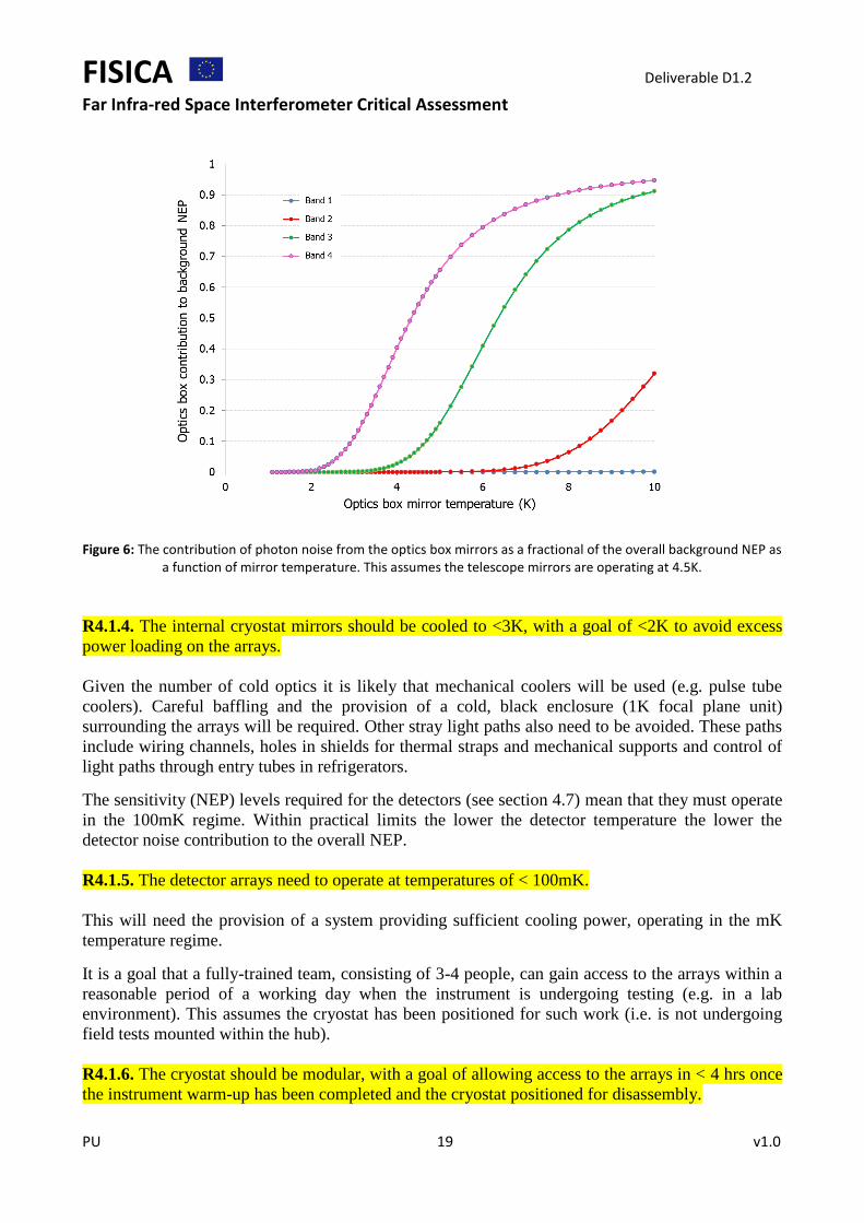
Figure 6 shows the contribution of photon noise from the optics box mirrors as a fraction of the
total background NEP as a function of mirror temperature. As can be seen the mirror temperature is
crucial at the longer wavebands, and needs to be 3K or less to contribute <20% of the background
power at band 4. A negligible contribution to the total background would be achieved by having the
mean optics box temperature at 2K or less.
FISICA Deliverable D1.2
Far Infra-red Space Interferometer Critical Assessment
PU 19 v1.0
Figure 6: The contribution of photon noise from the optics box mirrors as a fractional of the overall background NEP as
a function of mirror temperature. This assumes the telescope mirrors are operating at 4.5K.
R4.1.4. The internal cryostat mirrors should be cooled to <3K, with a goal of <2K to avoid excess
power loading on the arrays.
Given the number of cold optics it is likely that mechanical coolers will be used (e.g. pulse tube
coolers). Careful baffling and the provision of a cold, black enclosure (1K focal plane unit)
surrounding the arrays will be required. Other stray light paths also need to be avoided. These paths
include wiring channels, holes in shields for thermal straps and mechanical supports and control of
light paths through entry tubes in refrigerators.
The sensitivity (NEP) levels required for the detectors (see section 4.7) mean that they must operate
in the 100mK regime. Within practical limits the lower the detector temperature the lower the
detector noise contribution to the overall NEP.
R4.1.5. The detector arrays need to operate at temperatures of < 100mK.
This will need the provision of a system providing sufficient cooling power, operating in the mK
temperature regime.
It is a goal that a fully-trained team, consisting of 3-4 people, can gain access to the arrays within a
reasonable period of a working day when the instrument is undergoing testing (e.g. in a lab
environment). This assumes the cryostat has been positioned for such work (i.e. is not undergoing
field tests mounted within the hub).
R4.1.6. The cryostat should be modular, with a goal of allowing access to the arrays in < 4 hrs once
the instrument warm-up has been completed and the cryostat positioned for disassembly.

FISICA Deliverable D1.2
Far Infra-red Space Interferometer Critical Assessment
PU 20 v1.0
4.2 Delay line and re-imaging optics
Interferometry and spectroscopy with FIRI rely on accurate delay lines. For accurate spectroscopic
phase retrieval and ghost line suppression, it has been shown that sampling accuracy better than
0.1% of the shortest wavelength is required (Davis et al. 2001).
R4.2.1. The sampling accuracy required for the linear translation stage for the delay line is 0.1% at
the shortest wavelength.
A major challenge is to achieve this requirement in space and at cryogenic temperatures. This is the
subject of a separate work-package (D3.1) led by the University of Lethbridge. In this activity a
Renishaw differential laser interferometer will be used to evaluate the performance of a cryogenic
translation stage mounted in a pulse-tube cooled 4K cryostat. In addition to studying cryogenic
metrology issues, the work will investigate the performance of critical components such as beam
splitters and filters at their nominal operating temperatures.
The opto-mechanical design will determine the exact requirement for re-imaging optics within the
cryostat. The mirrors that make up the optical delay line and re-imaging optics (e.g. flat or powered
mirrors) should be easy to manufacture, and have a surface finish (micro-roughness) of < 140nm
RMS to contribute negligible efficiency loss due to scattering (see section 3.3).
R4.2.2. The surface accuracy of the delay line and re-imaging mirrors should be 140nm RMS or
better.
The emissivity of the mirror surfaces should ideally be minimised with a goal of less than 3%
across the spectral band per mirror.
R4.2.3. The emissivity of the mirror surfaces within the cryostat should be < 3%.
In addition, the choice of optical components that make up the delay lines is crucial. For example,
roof-top mirrors allow the most compact configuration minimising the overall optical path length in
the cryostat as well as diffraction effects.
4.3 Filtering and dichroic
The instrument will use two types of filters: bandpass filters to select the passbands for the
observations and low-pass (or edge) filters to block shorter (optical/IR) wavelength radiation. The
bandpass filters must have high efficiency (>80%) and low harmonic leaks so as not to contribute to
a potential stray light issue.
R4.3.1. Bandpass filters have a requirement of >80% transmission and <1% out-of-band power.
The bandpass is to be located close to the array (in the near-field of the detector to aid the control of
any ghosting), and will have a circular cross-section (in manufacture). As an alternative to a
bandpass filter the passband could also be defined using high-efficiency low- and high-pass edge
filters. The optical design and their chosen location in the instrument govern the diameter of the
filters. Filters of the anticipated size required have been manufactured before.
It may be necessary to fine-tune the gap between bandpass filter and the array. Hence, there should
be provision for varying the gap between the filter and the array (probably using shims).
FISICA Deliverable D1.2
Far Infra-red Space Interferometer Critical Assessment
PU 21 v1.0
R4.3.2. Provision is needed to vary the gap between the bandpass filter and the array by up to 3.
Infrared blocking and low-pass filters will also be needed on the radiation shields at 10, 4 and 1K
(temperatures to be confirmed upon completion of the cryostat design). Again these will be
manufactured as circular components. The diameter of the filters is dictated by the opto-mechanical
design.
R4.3.3. IR blocking and low-pass filters on radiation shields will each have > 95% transmission for
wavelengths longer than the cut-off.
Observations at 4 wavelengths simultaneously mean that high efficiency dichroic beamsplitters are
needed. Such dichroics have been developed for other instruments. The dichroic must also work
with high efficiency at the angle of incidence required for the opto-mechanical design of the focal
plane units.
R4.3.4. High efficiency dichroics with > 95% transmission and reflectance at an appropriate cut-off
wavelength are required for each spectral band.
4.4 Beam combiner
The beam from both telescopes interferes at the beam combiner with the subsequent interferograms
recorded by the detector arrays. The beam combiner needs to have excellent transmissive and
reflective properties with low emissivity.
R4.4.1. The beam combiner will have 49% transmission and reflection over the spectral band.
R4.4.2. The beam combiner will have ≤ 1% emissivity over the spectral band.
4.5 Cold stop and baffling
One option for the detector architecture is to use bare arrays (i.e. not feedhorn-coupled). If this is
the case then it will be necessary to control the 2 steradian detector field-of-view with a cold stop,
ideally placed near to the detector focal plane, possibly at the entrance of a 1K box surrounding the
arrays and bandpass filters.
R4.5.1. For bare arrays a cold stop will define the detector field-of-view.
Hence, the optics needs to be designed to ensure a high-quality pupil image of the secondary mirror
at a cold stop within the cryostat. It must also be ensured that the pupil imaging at the cold stop is
maintained with minimal variation in illumination as the telescope aspect changes. The optical
design will determine the cold stop diameter and optimum location.
R4.5.2. The optical design will determine the optimum diameter and location of the cold stop.
It may also be necessary to change the cold stop to optimise the detector coupling and control
background power. Therefore, the design should allow for the stop to be manually changed if
needed.
R4.5.3. The cold stop design must allow changeable apertures to be inserted.

FISICA Deliverable D1.2
Far Infra-red Space Interferometer Critical Assessment
PU 22 v1.0
The cryostat should contain optical baffles and other measures (e.g. low emissivity surfaces) to
minimise stray light. This includes sources of stray light such as wiring ports, thermal links and heat
generated by mechanisms.
4.6 Detector arrays
At the heart of the instrument are the detector arrays which are crucial to achieving the science
goals of the mission. The detectors must operate with high efficiency over the spectral range of the
instrument and meet the demanding sensitivity requirements. Kinetic inductance detectors are the
most promising candidate for the choice of detector technology at the current time. They also have
the potential to be mass-produced into the large-format arrays needed for low-background operation
at these wavelengths. However, other technologies should not be precluded at this stage with the
final choice being made after further assessment.
R4.6.1: The choice of detector technology will be down-selected from an assessment of the
available options at the time.
To produce an instantaneous, fully (Nyquist) sampled image of the sky requires that the detectors be
spaced by 0.5F in the re-imaged focal plane (where F is the focal ratio of the final optics). This
will be assumed to be the preferred pixel spacing pending further discussion on the relative merits
of using bare arrays, feedhorns or Winston cones to couple to the telescope beam.
R4.6.2: The pixel spacing in the focal plane at all wavelengths will be 0.5Fλ.
Representative pixel counts, required to fully-sample the sky within the 1 arcmin diameter field-of-
view (2 arcmin goal) are given in Table 3. The final pixel totals will depend critically on the optical
design. For the example case shown in Table 3 it has been assumed that the telescope focal ratio is
f/10 and at the arrays the optical beam is f/3. To ensure Nyquist sampling across the band the lower-
edge cut-off wavelength has been used.
Band Lower cut-off wavelength
(µm)
Pixel geometry/count
1 1 arcmin f-o-v
Pixel geometry/count
2 2 arcmin f-o-v
1 25 48 48 (2304) 96 96 (9216)
2 50 24 24 (576) 48 48 (2304)
3 100 12 12 (144) 24 24 (576)
4 200 6 6 (36) 12 12 (144)
Table 3: Representative pixel counts for the instrument
R4.6.3. The pixel geometry/count for band 1 will be of order 48 48 (2304) with a goal of 96 96
(9216).
R4.6.4. The pixel geometry/count for band 2 will be of order 24 24 (576) with a goal of 48 48
(2304).
R4.6.5. The pixel geometry/count for band 3 will be of order 12 12 (144) with a goal of 24 24
(576).

FISICA Deliverable D1.2
Far Infra-red Space Interferometer Critical Assessment
PU 23 v1.0
R4.6.6. The pixel geometry/count for band 4 will be of order 6 6 (36) with a goal of 12 12
(144).
Ideally, the overall instrument sensitivity should be limited by the background photon noise (from
the sky and telescope) and not by the intrinsic detector or electronics/readout noise. This means
adopting a detector noise equivalent power (NEP) of half that of the minimum background noise.
The FISICA sensitivity model spreadsheet (see Appendix A1) estimates the background NEP from
the sky, telescope and instrument using a representative model for the overall “Strawman” system.
The requirement for the detector NEP is that it be half that level or less, so when added in
quadrature will add no more than 12% to the total NEP. The detector NEP values are summarised in
Table 4.
Band Central wavelength
(µm)
Background photon noise NEP
(W/√Hz)
Required detector NEP
(W/√Hz)
1 37.5 1.6 10-18 7.7 10-19
2 75 1.1 10-18 5.6 10-19
3 150 9.4 10-19 4.7 10-19
4 300 1.8 10-18 9.1 10-19
Table 4: Summary of the background photon noise and required detector NEP values for the 4 bands
R4.6.7. The requirement NEP for a B1 detector is < 7.7 10-19 W/Hz.
R4.6.8. The requirement NEP for a B2 detector is < 5.6 10-19 W/Hz.
R4.6.9. The requirement NEP for a B3 detector is < 4.7 10-19 W/Hz.
R4.6.10. The requirement NEP for a B4 detector is < 9.1 10-19 W/Hz.
To achieve such NEP levels will require detector operating temperatures of < 100mK (see section
4.1).
Assuming a stare mode of observation the pixel yield on each array should be maximised to avoid
having perform a micro-step (e.g. using the secondary mirror) to maintain Nyquist sampling of an
area of sky. A realistic requirement is to have array yields of at least 90%.
R4.6.11. The pixel yield for each detector array will be 90%.
If a stare mode is to be used then the distribution of bad pixels is also important. Therefore, in
addition to the 90% yield criterion there is also a specification on the distribution of bad pixels on
an array. There should be no two (or more) adjacent bad rows or columns, and there should be no
“clusters” of more than 4 × 4 bad pixels.

FISICA Deliverable D1.2
Far Infra-red Space Interferometer Critical Assessment
PU 24 v1.0
R4.6.12. The detector array must not have adjacent bad columns or rows, as well as no dead
clusters of greater than 4 × 4 pixels.
Power from a source must be coupled as efficiently as possible to the detector element. For
example, when coupling to a point source this depends on the relative size of a pixel with respect to
the Airy disk. For 0.5Fλ sized pixels the maximum coupling efficiency to a point source is 16%
(assuming a near perfect illumination pattern of the primary, negligible obscuration by the
secondary). The requirement is that the coupling be maximised with a goal of >15%.
R4.6.13. The optical coupling efficiency for an individual 0.5Fλ detector should be maximised with
a goal of 15% for all spectral channels.
The detector element must also been designed to maximise the radiation absorption efficiency. It
should be possible to design absorbing substrates that can achieve at least 80% absorption
efficiency.
R4.6.14. The absorption efficiency for an individual detector should be 80% for all spectral
channels.
Not only do the detectors need to have the required sensitivity to meet the science goals but they
also need a fast enough response time to accommodate the observing strategies. In particular, the
detector time constant must be shorter than the time required by the delay line to move one
sampling step.
R4.6.15. The detector time constant needs to be of order 0.2 msec.
Future work:
1. Depending on the operational mode(s) it may be necessary to set a requirement for the “1/f
knee” frequency for the detector noise. Other things to potentially consider:
4.7 Electronics/signal readout requirements
The data acquisition system must read out the detector signals at a rate of at least 3 detector time
constants to avoid possible aliasing of noise into the signal band. This corresponds to a minimum
data acquisition frequency of approximately 1.7 kHz per pixel. Assuming frequency domain
multiplexing the read out rate should be of order 2 kHz.
R4.7.1. The data acquisition system must read out each detector signal at a rate of ~ 2 kHz.
For example, the maximum scan speed (set so that sampling yields a Nyquist frequency coincident
with the high frequency edge of the band) depends solely on the data acquisition rate and the
Nyquist (over)sampling factor.
The number of bits required to digitise the detector output also needs to take into account
engineering requirements, such as the necessity to measure "system noise" with the cryostat
window blanked off (i.e. there will be negligible photon noise from the sky or telescope). The data
acquisition system must therefore have at least 16-bits over the entire dynamic range of input
signals.

FISICA Deliverable D1.2
Far Infra-red Space Interferometer Critical Assessment
PU 25 v1.0
R4.7.2. The data acquisition system must have at least 16 bits to digitise the signal.
As discussed in section 4.7 the requirement is that the background photon noise from the sky and
telescope dominate the overall noise levels. This means adopting a design detector NEP at least half
that of the minimum background noise. Noise levels due to non-TES sources (i.e. associated with
the readout scheme) should cause the detector NEP to increase by no more than 20%.
R4.7.3. Non-detector noise should cause no more than a 20% increase in the detector NEP.
FIRI is expected to observe astronomical sources over a wide range of flux levels. The achievable
dynamic range in an image will most likely be limited by crosstalk. The effect of crosstalk
manifests itself as an unwelcome or ghost signal falling onto a neighbouring pixel. Crosstalk can be
split into two components: electrical crosstalk (arising, for example, from the way the signal
readouts are wired) and optical spillover (caused by the diffraction pattern of the telescope). It is the
level of optical spillover that sets the (unavoidable) crosstalk limit for the instrument. For nearest
neighbour pixels the diffraction pattern of the telescope means that optical spillover dominates. It is
the electrical crosstalk from non-nearest neighbours that is potentially a problem.
For observations for which the signal dynamic range is low in any case (e.g. deep extragalactic) this
should not be a major concern. It is more critical for observations that contain one or more “bright”
point-like sources in the field surrounded by fainter emission (which contains additional sources of
interest). Hence, it will be quite likely that observations of galactic star forming regions (which
contain at least some “bright” sources) will set the crosstalk requirement for the instrument. The
specification for this depends on the map dynamic range (MDR) that is acceptable. A MDR of
200300 might be reasonable and so this sets the crosstalk limit to be around 0.3%.
R4.7.4. The distant pixel crosstalk is required to be < 0.3%.
Future work:
1. Consider requirements for the attenuation of stray magnetic fields (e.g. from motors).
2. Consider requirements for RF shielding (perhaps of particular concern for the FDM?).
5. Operational requirements
5.1 Observing modes
The ultimate scientific potential of FIRI depends critically on the ability to observe survey fields for
very long times with possible multiple field orientations, with possible total exposure times of
several days. Long exposure times will be needed to provide scans covering the entire u-v plane. To
obtain an image of a sky area is necessary to perform spectrographic interferometry for every single
point in the 𝑢, 𝑣 plane maintaining the spatial coherence (compared to some known sources). Every
single (𝑢, 𝑣) point acquired by the interferometer, gives the spatial Fourier component for a fixed
distance between the sources contained in the sky area in observation and in a direction parallel to
the telescope baseline and for the various spectroscopic components.
Future work:

FISICA Deliverable D1.2
Far Infra-red Space Interferometer Critical Assessment
PU 26 v1.0
1. Derive any specific requirements related to either exposure times or the ability to cover the
u-v plane for particular observations (really part of a future Operational Concept
Definition).
5.2 Calibration
Observations in the far-infrared from space rely on three basic kinds of calibration. Firstly, at the
instrument level calibration sources are used, for example, to disentangle uncertainties in the optics
and to regularly measure the linearity of the detector arrays (“flat-field”). The design of such
calibrators is the subject of a separate work-package report (D3.5) by University College London.
R.5.2.1 The instrument will have the provision for one of more internal calibrators to assess the
performance of the optics and detector arrays.
Another possibility is that a compact “telescope simulator” could be used to mimic the full-sized
interferometer, providing diffraction-limited beams that would be used to evaluate the optical
system (and potentially carry out simulated observations).
Secondly, it will be necessary to measure well-characterised astronomical objects to provide flux
and line calibration for the detector outputs.
R.5.2.2 The instrument will be capable of rapidly carrying out routine, calibration observations of
flux and line standards.
Finally, it is also necessary to be able to periodically make an accurate measurement of the
telescope beam shape, using observations of a bright, point-like source, to ensure that the full
optical system is performing as expected (e.g. diffraction-limited beam size and sidelobe levels are
well characterised).
R.5.2.3 The instrument will carry out periodic measurements of a bright, point-like source to enable
a full characterisation of the telescope beam shape.
5.3 Sky coverage
The field of regard should allow access to all desirable science targets. This needs to be determined
but a nominal field of 40⁰ band centered on the ecliptic (i.e. similar to proposed for SPECS and
SPIRIT) is a reasonable first assumption.
R.5.3.1 The field of regard for the satellite should be a 40⁰ band centered on the Ecliptic (TBC).
5.4 Time to acquire an object
To time to acquire a target needs to be minimised as far as is practical. The time to slew to a target
over a large angle (anywhere on the sky, but noting that large slews should be few in numbers
within a well-planned programme) should be 10 minutes or less.
R.5.4.1 The time to slew to a target over a large angle (anywhere on the sky) should be < 10 mins.
Similarly, the time to slew to relatively nearby targets, e.g. next science target or calibration source,
say within 45 degrees cone angle, should be less than 2 mins.

FISICA Deliverable D1.2
Far Infra-red Space Interferometer Critical Assessment
PU 27 v1.0
R.5.4.2 The time to slew to a target over a small angle (within a cone angle of 45 degrees) should
be < 2 mins.
After a slew is complete it will be necessary to allow some time for the entire satellite and
instrument to settle. Again, this should be minimised with a requirement of 0.5 minutes.
R.5.4.3 After a slew a settling time of 0.5 minutes will be allowed, with a goal to reduce this time as
far as practical.
5.5 Metrology
The overall instrument (including telescope) needs several highly accurate metrology sub-systems.
Knowledge of the origin and propagation of phase and positional errors along the optical path is
critical to fringe visibility and interferogram reconstruction. Ultimately, an overall error budget will
need to be constructed that assesses all possible causes or error. Further work on this is also
presented in report 1.3.
For example, further work is needed to assess the maximum allowable optical path difference
(OPD) of the two beams. Sporadic, modest “jumps” of order λ/4 can most likely be contained, but
bearing in mind the wideband of operation, the RMS of the OPD will need to be constrained to
much tighter tolerance (of order tens of nm).
Other metrology information:
1. Requirements on fringe tracking/monitoring/OPD accuracy.
2. Telescope position and altitude monitoring.
3. Relative tip/tilt displacement monitoring of the beams.
4. Alignment sensing for the telescope optical axis with respect to the detector array focal
planes.
Future work:
1. Assess the requirements of these metrology systems.
5.5 Mission lifetime
The mission lifetime should be dictated by the science to be undertaken, but in practical terms is
likely to be limited by the amount of propellant to manoeuvre the spacecraft and the mechanical
reliability of key system (e.g. telescope motors, closed-cycle coolers). To maximise the lifetime will
require the careful planning of observations to minimise spacecraft movements. Hence, the lifetime
should be maximised with a minimum requirement of 5 years.
R.5.5.1 The mission lifetime should be maximised with a minimum requirement of 5 years.

FISICA Deliverable D1.2
Far Infra-red Space Interferometer Critical Assessment
PU 28 v1.0
References O’Sullivan C., “Effect of surface irregularities on fringe visibility”, Internal FISICA report, (draft dated
10/5/14)
Spinoglio L., 2014, “Definition/update of key science questions and relevant data products, FISICA
deliverable report D1.1” (July 2014).
Davis S. P., et al., 2001, Fourier Transform Spectrometry (Academic Press)
Goldsmith, P., 1998, Quasioptical Systems, (IEEE Press, New York)
Appendices
Appendix A1
FISICA sensitivity model
A spreadsheet-based model has been constructed to estimate the performance of the current
“Strawman” instrument for astronomical observations. This approach has considerable heritage
from pervious instruments (such as Herschel/SPIRE and SCUBA-2) and also borrows concepts and
ideas from current missions and conceptual studies (e.g. BETTII, SPIRIT and SPECS).
The spreadsheet is designed into separate worksheets (or modules) that detail all areas of the
system, such as the spacecraft, interferometer, telescope system, instrument cold optics and
detectors, and electronics and readout. The current version assumes a near-perfect optical system
with component parameters (e.g. sizes, temperatures, emissivities etc.) as specified in this
document. There are a number of further assumptions that have been included in the current version
of the model:
Sensitivity model assumptions:
1. Telescope: A 5-mirror telescope system (conservative, to, for example, allow for more beam
folding if required or the need for a beam steering mirror).
2. Throughput: The optical throughout (“etendue”) is assumed to be single-moded (AΩ = λ2).
There is no account for imperfect coupling of the beam from the detector to the telescope
primary mirror (e.g. edge-taper illumination).
3. Instrument: The baseline layout for the instrument is as given in Figure 5.
4. Stray light: Although a modest factor of 1% has been included for the internal optics it is
possible that this is underestimated.
Further worksheets then estimate the background power arriving at the detector, taking into account
the sky (e.g. Zodiacal light, infrared and microwave backgrounds), and emission from the telescope
and instrument components. These levels are then used to derive the expected background photon
noise level at the detector. To gain a level of confidence in the results an independent approach was

FISICA Deliverable D1.2
Far Infra-red Space Interferometer Critical Assessment
PU 29 v1.0
also adopted (using MathCad) to model the sensitivity for subsets of the optical system. This
method led to agreement with the spreadsheet approach to within 10%.
Figure A1.1 shows a plot of the relative contribution to the overall background photon noise NEP
from the sky, telescope and instrument for all 4 bands. For band 1 it can be seen that the
unavoidable zodiacal light provides the overwhelming limit to sensitivity. At band 2 the zodi
contribution is also dominant but with an increasing contribution from the cosmic infrared
background. For band 3 the CIB and zodi dominate, whilst at the longer band 4 it is the telescope
and CIB that are the main contributions.
Figure A1.1: The relative contribution to the overall photon noise from the sky, telescope and
instrument for the 4 wavebands.
Table A1 summarises the estimated background power and NEPs (per detector element) for each of
the 4 spectral bands. The results of the point-source sensitivity (NEFD) and line fluxes calculations
at each waveband are also given.
Parameter Units Band 1 Band 2 Band 3
Band 4
Background power
W 4.03 10-16 3.16 10-16 2.78 10-16 1.33 10-15
Background photon noise NEP
W/√Hz 1.55 10-18 1.07 10-18 9.37 10-19 1.81 10-18
Detector NEP(1)
W/√Hz 7.74 10-19 5.57 10-19 4.69 10-19 9.06 10-19
Overall system NEP(3)
W/√Hz 2.50 10-18 1.25 10-18 1.09 10-18 2.11 10-18
Noise equivalent flux density (NEFD)
µJy/√Hz
266 448 903 3823
Point-source detection limit(3) (5σ, 1hr)
µJy 9.9 16.7 28.5 110
Point-source spectro- photometry(3) (5σ, 1hr) at R=5
µJy 37.2 51.7 90.3 349

FISICA Deliverable D1.2
Far Infra-red Space Interferometer Critical Assessment
PU 30 v1.0
Point-source limiting line strength(3) (5σ, 1hr)
W/m2 6.0 10-19 4.1 10-19 3.6 10-19 7.0 10-19
Table A1: Summary of the results from the FISICA sensitivity model per detector. The table also includes estimates of the point-source detection limit, detection limit for spectrophotometry at R=5 and a limiting line strength.
Table notes: 1 The detector NEP is set to be half that of the background photon noise NEP (see R4.6.7-10) 2 The overall NEP is the quadrature sum of the background NEP and detector NEP (allowing for an extra 20% to the detector NEP
for non-detector noise contributions (e.g. from the readout – see R4.7.3). 3 Includes the contribution from both telescopes, taking into account interferometric efficiency.
To put these results into perspective Figure A1.1 shows how the performance of FIRI, based on the
current FISICA study design and sensitivity model, compares with other recent and future missions
in terms of sensitivity.
FISICA Deliverable D1.2
Far Infra-red Space Interferometer Critical Assessment
PU 31 v1.0
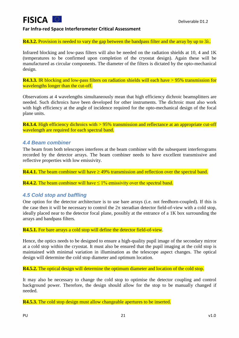
Figure A1: (Top) Point-source detection limit (5σ, 1hr) for spectrophotometry (R=5) for FIRI-FISICA and other missions; (Bottom) The limiting line flux achievable from a point-source (5σ, 1hr) for FIRI-FISICA and other missions. The dashed black lines give the approximate sensitivity requirements levels as outlined in this document (section 2.4) in each case.
Top Related