


Languages
Pages
Legal


Test report # PF21009-A
Test Number 21009
Issued to: Intex International
Fire resistance tests for wall penetrations
Test method: AS 1530.4:2014
Report Date 17/09/2021

Report # PF21009 dated 17-Sept-2021 Page 2 of 55
1. Table of Contents
1. Table of Contents ................................................................................................................ 2
1.1 Document revision schedule ....................................................................................... 4
1.2 Signatories ................................................................................................................... 4
2. Contact details ..................................................................................................................... 5
2.1 IANZ registered Testing Authority ............................................................................... 5
2.2 Issued to....................................................................................................................... 5
2.3 Manufacturer ............................................................................................................... 5
3. Test Results ......................................................................................................................... 6
4. Test Details .......................................................................................................................... 7
5. Equipment ........................................................................................................................... 9
6. Test Conditions .................................................................................................................. 10
6.1 Furnace Temperature ................................................................................................ 10
6.2 Ambient Temperature ............................................................................................... 10
6.3 Pressure Readings ...................................................................................................... 11
7. Schedule of materials ........................................................................................................ 12
8. Test Specimens details ...................................................................................................... 17
8.1 Thermocouple Positions Table .................................................................................. 17
8.2 Observations .............................................................................................................. 21
9. Separating element and main fire-stopping system ......................................................... 23
10. Specimens ..................................................................................................................... 24
10.1 Specimen A ................................................................................................................ 25
10.2 Specimen B ................................................................................................................ 28
10.3 Specimen C ................................................................................................................ 31
10.4 Specimen D ................................................................................................................ 34
10.5 Specimen E................................................................................................................. 37
10.6 Specimen F ................................................................................................................. 40
10.7 Specimen G ................................................................................................................ 44
10.8 Specimen H ................................................................................................................ 47
11. Additional photographs................................................................................................. 49
Report # PF21009 dated 17-Sept-2021 Page 3 of 55
11.1 Materials used ........................................................................................................... 49
11.2 During and after the test ........................................................................................... 50

Report # PF21009 dated 17-Sept-2021 Page 4 of 55
1.1 Document revision schedule
Revision # Date Description
1 24/08/2021 Initial Issue for Client review
2 11/09/2021 Issued with Client comments
3 17/09/2021 Issued to Intex International
1.2 Signatories
Report Name Signature Date
Prepared by: Alexey Kokorin (Technical Manager)
17/09/2021
Authorized by: Andrew Bain (Authorized signatory)
17/09/2021

Report # PF21009 dated 17-Sept-2021 Page 5 of 55
2. Contact details
2.1 IANZ registered Testing Authority
Passive Fire Inspection and Test Services Ltd
Accreditation No: 1335
1/113 Pavilion Drive, Mangere, Auckland, 2022
New Zealand
Contact e-mail: [email protected]
2.2 Issued to
Intex International
91-115 Link Drive, Campbellfield, Victoria Australia, 3061
Australia
Contact e-mail: [email protected]
2.3 Manufacturer
RLA Polymers Pty Ltd
215 Colchester Road, Kilsyth, Victoria, 3137
Australia
Report # PF21009 dated 17-Sept-2021 Page 6 of 55
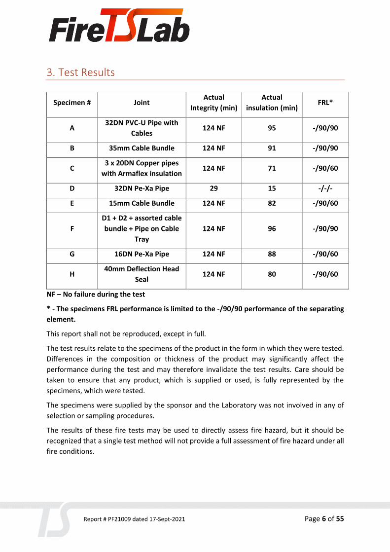
3. Test Results
Specimen # Joint Actual
Integrity (min)
Actual
insulation (min) FRL*
A 32DN PVC-U Pipe with
Cables 124 NF 95 -/90/90
B 35mm Cable Bundle 124 NF 91 -/90/90
C 3 x 20DN Copper pipes
with Armaflex insulation 124 NF 71 -/90/60
D 32DN Pe-Xa Pipe 29 15 -/-/-
E 15mm Cable Bundle 124 NF 82 -/90/60
F
D1 + D2 + assorted cable
bundle + Pipe on Cable
Tray
124 NF 96 -/90/90
G 16DN Pe-Xa Pipe 124 NF 88 -/90/60
H 40mm Deflection Head
Seal 124 NF 80 -/90/60
NF – No failure during the test
* - The specimens FRL performance is limited to the -/90/90 performance of the separating
element.
This report shall not be reproduced, except in full.
The test results relate to the specimens of the product in the form in which they were tested.
Differences in the composition or thickness of the product may significantly affect the
performance during the test and may therefore invalidate the test results. Care should be
taken to ensure that any product, which is supplied or used, is fully represented by the
specimens, which were tested.
The specimens were supplied by the sponsor and the Laboratory was not involved in any of
selection or sampling procedures.
The results of these fire tests may be used to directly assess fire hazard, but it should be
recognized that a single test method will not provide a full assessment of fire hazard under all
fire conditions.

Report # PF21009 dated 17-Sept-2021 Page 7 of 55
4. Test Details
Test Specification Fire Resistance:
Failure shall be deemed to have occurred when one of the following occurs:
a) the temperature at any location on the unexposed face of the test specimen exceeds the
initial temperature by more than 180 °C
b) Integrity failure shall be deemed to have occurred upon ignition of the cotton pad when
glowing or flaming occurs for a period of 30 seconds.
c) Flaming to the unexposed face for 10 seconds or longer shall be deemed to be an Integrity
failure.
d) Integrity failure shall be deemed to occur when a 6mm gap gauge can be passed through
the specimen so that the gap gauge projects into the furnace and can be moved a distance of
150mm along the gap.
e) Integrity failure shall be deemed to occur when a 25mm gap gauge can be passed through
the specimen so that the gap gauge projects into the furnace
Testing scope:
AS 1530-2014 Part 4 Section 10 Service penetrations and control joints
AS 4072.1-2005 Part 1 Appendix A - Typical examples of fire-stopping systems for movement
joints.
Documentation:
Testing products were verified and tested based on Client description, refer to Specimens
description below. All drawings were provided by Client, in case of any difference between
the drawings and report description, the text description shall prevail.
Testing date: Installation completion date:
02/08/2021 22/07/2021
Specimens conditioning and delivery to Laboratory:
Separating element was built by Laboratory in line with Client instructions. Installation of fire
stopping system was performed by Client. The Laboratory was not involved in sampling of the
materials. Laboratory verified materials during construction of the specimen. The Client

Report # PF21009 dated 17-Sept-2021 Page 8 of 55
confirmed in writing that BlazeBlocker® Fire Rated Sealant is based on the same formulation
as FirePro FR Acrylic Sealant and has identical chemical composition, manufacturing process
and properties.
Termination of The Test:
The test was discontinued at 124 minutes.
Use of Reports:
This report shall not be reproduced, except in full.
This report details the methods of construction, test conditions and the results obtained when
the specific element of construction described herein was tested following the procedure
outlined in AS 1530.4. Any significant variation with respect to size, constructional details,
loads, stresses, edge or end conditions, other than that allowed under the field of direct
application in the relevant test method, is not covered by this report.
Because of the nature of fire resistance testing and the consequent difficulty in quantifying
the uncertainty of measurement of fire resistance, it is not possible to provide a stated degree
of accuracy of the result.

Report # PF21009 dated 17-Sept-2021 Page 9 of 55
5. Equipment
Furnace:
1200X1200 Indicative Furnace designed to operate to AS1530.4:2014
Temperature:
Furnace Temperature measurements were controlled with four 3mm Type K MIMS
thermocouples set within 50-100 mm from the face of the specimens in line with AS1530.4-
2014. All thermocouples are calibrated by ISO/IEC 17025 accredited laboratory - a signatory
to the International Laboratory Accreditation Corporation (ILAC) through their Mutual
Recognition Agreement (MRA) to the accuracy required by AS 1530.4-2014.
Pressure measurement:
Kepware Siemens Data logging system including multi-channel recording data at 5 second
intervals. Calibrated by ISO/IEC 17025 accredited laboratory - a signatory to the International
Laboratory Accreditation Corporation (ILAC) through their Mutual Recognition Agreement
(MRA) to the accuracy required by AS 1530.4-2014.
Ambient Temperature:
Ambient temperature was recorded 15 minutes before the test was commenced, at the start
of the test and monitored during the test. All thermocouples are calibrated by ISO/IEC 17025
accredited laboratory - a signatory to the International Laboratory Accreditation Corporation
(ILAC) through their Mutual Recognition Agreement (MRA) to the accuracy required by AS
1530.4-2014.
Specimen thermocouples:
Specimen thermocouples were installed to the unexposed face. Type K copper disk
thermocouples fixed within the required locations referenced from AS1530.4-2014.
Thermocouples are calibrated by ISO/IEC 17025 accredited laboratory - a signatory to the
International Laboratory Accreditation Corporation (ILAC) through their Mutual Recognition
Agreement (MRA) to the accuracy required by AS 1530.4-2014.
Dimensional measurements:
All linear measurements are made with equipment calibrated by ISO/IEC 17025 accredited
laboratory - a signatory to the International Laboratory Accreditation Corporation (ILAC)
through their Mutual Recognition Agreement (MRA) to the accuracy required by AS 1530.4-
2014.

Report # PF21009 dated 17-Sept-2021 Page 10 of 55
6. Test Conditions
6.1 Furnace Temperature
The furnace was controlled to follow the temperature/time relationship specified in
AS 1530.4-2014 as closely as possible.
6.2 Ambient Temperature
The ambient temperature of the test area 15 minutes before the test and at the
commencement of the test was 18 °C.

Report # PF21009 dated 17-Sept-2021 Page 11 of 55
6.3 Pressure Readings
The furnace pressure was maintained at 16 ± 3 Pa with respect to atmosphere. The probe was
located 500mm above the furnace floor.

Report # PF21009 dated 17-Sept-2021 Page 12 of 55
7. Schedule of materials
All firestopping products were supplied and installed by Client.
Separating Element
1.1 Item / Product Name 92mm Steel Stud Plasterboard Separating element with 1
layer of 16mm firerated plasterboard each side
Measurements Width / Height (W/H): 1200mm x 1060mm
Thickness (T): 126mm
1.2 Item / Product Name Rondo 92mm Steel Stud
Measurements Width / Height (W/H): 92mm x 29mm
Thickness (T): 1mm
Installation Used to construct separating element
1.3 Item / Product Name Rondo 92mm Steel Track
Measurements Width / Height (W/H): 94mm x 29mm
Thickness (T): 0.75mm
Installation Used to construct separating element
1.4 Item / Product Name Rondo Deflection Head Track
Measurements Width / Height (W/H): 94mm x 50mm
Thickness (T): 1mm
Installation Used to construct separating element
1.5 Item / Product Name USG Boral Firestop Plasterboard
Measurements Width / Height (W/H): 1020mm x 1200mm
Thickness (T): 16mm
Installation Used to construct separating element
Services
2.1 Item / Product Name Nexans CU TPS Cable
Measurements Outer Diameter (OD): 11.99mm x 5.42mm
Additional Info Specimen A, B, E, F

Report # PF21009 dated 17-Sept-2021 Page 13 of 55
2.2 Item / Product Name FL@tCore Minimal Section Premise Optical Cable
Measurements Outer Diameter (OD): 2.88mm x 1.72mm
Additional Info Specimen A, B, E, F
2.3 Item / Product Name Dynamix UTP Cat6 Cable
Measurements Outer Diameter (OD): 5.85mm
Additional Info Specimen A, B, E, F
2.4 Item / Product Name 20mm Copper Pipe
Measurements Inner Diameter (ID): 16.01mm
Outer Diameter (OD): 19.09mm
Width (W): 1.48mm
Additional Info Specimen C
2.5 Item / Product Name Armacell Armaflex Nitrile Rubber Insulation
Measurements Inner Diameter (ID): 20.23mm
Outer Diameter (OD): 55.15mm
Width (W): 17.97mm
Additional Info Specimen C
2.6 Item / Product Name 32DN Kempex Pipe Pe-Xa
Measurements Inner Diameter (ID): 22.51mm
Outer Diameter (OD): 32.23mm
Width (W): 4.98mm
Additional Info Specimen D
2.7 Item / Product Name 16 DN Kempex Pipe Pe-Xa
Measurements Inner Diameter (ID): 10.49mm
Outer Diameter (OD): 16.05mm
Width (W): 2.25mm
Additional Info Specimen G
2.8 Item / Product Name 20mm IPLEX Volta PVC-U Pipe
Measurements Inner Diameter (ID): 16.70mm

Report # PF21009 dated 17-Sept-2021 Page 14 of 55
Outer Diameter (OD): 19.82mm
Width (W): 1.73mm
Additional Info Specimen F
2.9 Item / Product Name 32mm IPLEX Volta PVC-U Pipe
Measurements Inner Diameter (ID): 27.49mm
Outer Diameter (OD): 31.85mm
Width (W): 2.44mm
Additional Info Specimen A
2.10 Item / Product Name 50mm IPLEX Volta PVC-U Pipe
Measurements Inner Diameter (ID): 43.99mm
Outer Diameter (OD): 50.01mm
Width (W): 3.23mm
Additional Info Specimen F
2.11 Item / Product Name Galvanised Steel Cable tray
Measurements Width / Height (W/H): 450mm x 50mm
Thickness (T): 1.00mm
Additional Info Specimen F
2.12 Item / Product Name Single-core PVC Insulated Cable (D1 Cable Bundle)
Measurements Outer Diameter (OD): 40.72mm
Additional Info Specimen F
2.13 Item / Product Name Three core + Earth PVC Insulated Cable (D1 Cable Bundle)
Measurements Outer Diameter (OD): 53.40mm
Additional Info Specimen F
2.14 Item / Product Name Three core + Earth PVC Insulated Cable (D1 Cable Bundle)
Measurements Outer Diameter (OD): 14.43mm
Additional Info Specimen F
2.15 Item / Product Name Three core + Earth PVC Insulated Cable (D1 Cable Bundle)
Measurements Outer Diameter (OD): 22.59mm
Report # PF21009 dated 17-Sept-2021 Page 15 of 55
Additional Info Specimen F
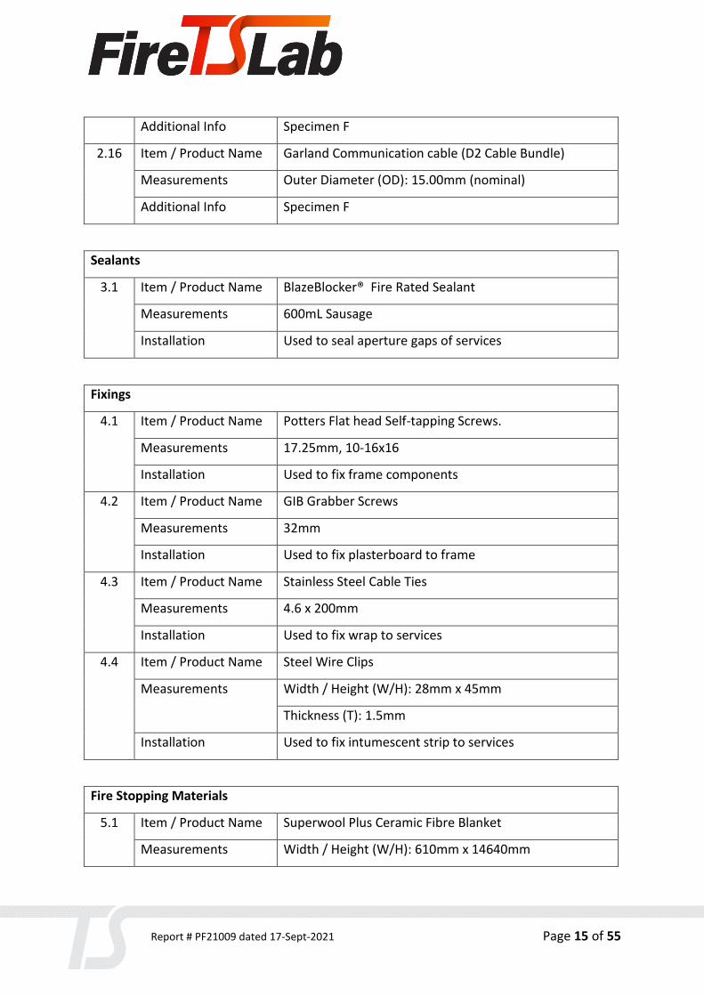
2.16 Item / Product Name Garland Communication cable (D2 Cable Bundle)
Measurements Outer Diameter (OD): 15.00mm (nominal)
Additional Info Specimen F
Sealants
3.1 Item / Product Name BlazeBlocker® Fire Rated Sealant
Measurements 600mL Sausage
Installation Used to seal aperture gaps of services
Fixings
4.1 Item / Product Name Potters Flat head Self-tapping Screws.
Measurements 17.25mm, 10-16x16
Installation Used to fix frame components
4.2 Item / Product Name GIB Grabber Screws
Measurements 32mm
Installation Used to fix plasterboard to frame
4.3 Item / Product Name Stainless Steel Cable Ties
Measurements 4.6 x 200mm
Installation Used to fix wrap to services
4.4 Item / Product Name Steel Wire Clips
Measurements Width / Height (W/H): 28mm x 45mm
Thickness (T): 1.5mm
Installation Used to fix intumescent strip to services
Fire Stopping Materials
5.1 Item / Product Name Superwool Plus Ceramic Fibre Blanket
Measurements Width / Height (W/H): 610mm x 14640mm

Report # PF21009 dated 17-Sept-2021 Page 16 of 55
Thickness (T): 13mm
Density (ρ): 128kg/m3
Installation Wrapped around services
5.2 Item / Product Name Expandawrap - Intumescent Strip
Measurements Width (W): 25mm
Thickness (T): 2.75mm
Installation Wrapped around services
Report # PF21009 dated 17-Sept-2021 Page 17 of 55
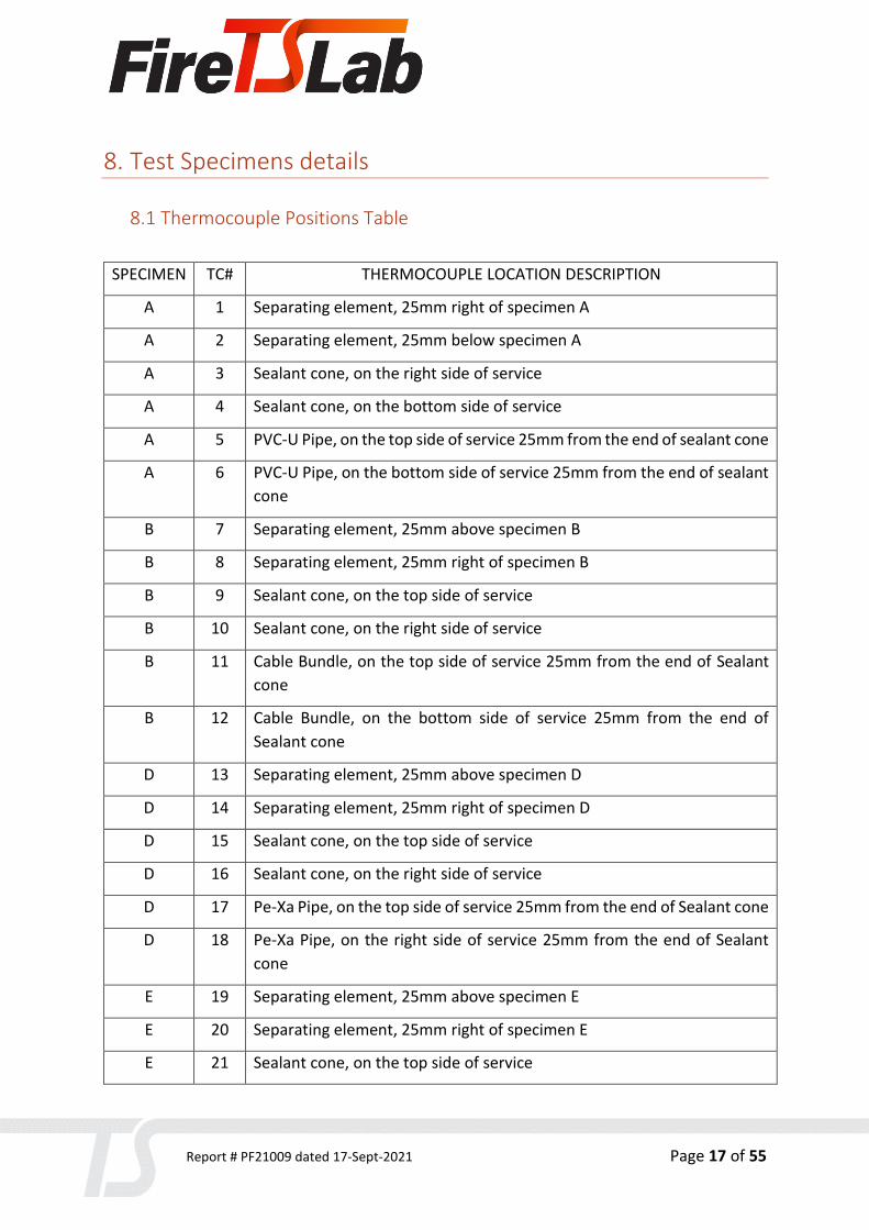
8. Test Specimens details
8.1 Thermocouple Positions Table
SPECIMEN TC# THERMOCOUPLE LOCATION DESCRIPTION
A 1 Separating element, 25mm right of specimen A
A 2 Separating element, 25mm below specimen A
A 3 Sealant cone, on the right side of service
A 4 Sealant cone, on the bottom side of service
A 5 PVC-U Pipe, on the top side of service 25mm from the end of sealant cone
A 6 PVC-U Pipe, on the bottom side of service 25mm from the end of sealant
cone
B 7 Separating element, 25mm above specimen B
B 8 Separating element, 25mm right of specimen B
B 9 Sealant cone, on the top side of service
B 10 Sealant cone, on the right side of service
B 11 Cable Bundle, on the top side of service 25mm from the end of Sealant
cone
B 12 Cable Bundle, on the bottom side of service 25mm from the end of
Sealant cone
D 13 Separating element, 25mm above specimen D
D 14 Separating element, 25mm right of specimen D
D 15 Sealant cone, on the top side of service
D 16 Sealant cone, on the right side of service
D 17 Pe-Xa Pipe, on the top side of service 25mm from the end of Sealant cone
D 18 Pe-Xa Pipe, on the right side of service 25mm from the end of Sealant
cone
E 19 Separating element, 25mm above specimen E
E 20 Separating element, 25mm right of specimen E
E 21 Sealant cone, on the top side of service

Report # PF21009 dated 17-Sept-2021 Page 18 of 55
E 22 Sealant cone, on the right side of service
E 23 Cable Bundle, on the top side of service 25mm from the end of Sealant
cone
E 24 Cable Bundle, on the bottom side of service 25mm from the end of
Sealant cone
SE 25 Separating element, Equidistant between Specimens C, D and E
G 26 Separating element, 25mm above specimen F
G 27 Separating element, 25mm right of specimen F
G 28 Sealant cone, on the top side of service
G 29 Sealant cone, on the right side of service
G 30 Pe-Xa Pipe, on the top side of service 25mm from the end of Sealant cone
G 31 Pe-Xa Pipe, on the bottom side of service 25mm from the end of Sealant
cone
C 32 Top left Armaflex copper pipe, on the top side of service 25mm from the
end of the intumescent strip
C 33 Top left Armaflex copper pipe, on the right side of service 25mm from
the end of the intumescent strip
C 34 Top right Armaflex copper pipe, on the top side of service 25mm from
the end of the intumescent strip
C 35 Top right Armaflex copper pipe, on the right side of service 25mm from
the end of the intumescent strip
C 36 Bottom Armaflex copper pipe, on the right side of service 25mm from the
end of the intumescent strip
C 37 Bottom Armaflex copper pipe, on the left side of service 25mm from the
end of the intumescent strip
C 38 Separating element, 25mm above specimen F
C 39 Separating element, 25mm right of specimen F
C 40 Sealant cone, above top left Armaflex copper pipe
C 41 Sealant cone, above top right Armaflex copper pipe
C 42 Sealant cone, below bottom Armaflex copper pipe
F 43 Separating element, 25mm above additional plasterboard of specimen F

Report # PF21009 dated 17-Sept-2021 Page 19 of 55
F 44 Separating element, 25mm right of additional plasterboard of specimen
F
F 45 Separating element, 25mm below additional plasterboard of specimen F
F 46 Additional plasterboard, 25mm above the ceramic blanket, above D2
configuration
F 47 Additional plasterboard, 25mm above the ceramic blanket, above D1
configuration
F 48 Ceramic Blanket, on the top side of service above D2 configuration,
25mm from separating element
F 49 Ceramic Blanket, on the top side of service above 50mm PVC-U Pipe,
25mm from separating element
F 50 Ceramic Blanket, on the top side of service above D1 configuration,
25mm from separating element
F 51 Ceramic Blanket, on the bottom side of service below D2 configuration,
25mm from separating element
F 52 Ceramic Blanket, on the bottom side of service below D1 configuration,
25mm from separating element
F 53 On cable bundle (2.16), on the top side of service, 25mm from the end of
the ceramic blanket
F 54 On PVC-U Pipe (2.10), on the top side of service, 25mm from the end of
the ceramic blanket
F 55 On cable bundle (2.15), on the top side of service, 25mm from the end of
the ceramic blanket
F 56 On cable bundle (2.14), on the top side of service, 25mm from the end of
the ceramic blanket
F 57 On PVC-U Pipe (2.8), on the top side of service, 25mm from the end of
the ceramic blanket
F 58 On cable bundle (2.13), on the top side of service, 25mm from the end of
the ceramic blanket
F 59 On cable bundle (2.12), on the top side of service, 25mm from the end of
the ceramic blanket
F 60 On cable tray (2.13), on the bottom side of service, below D2
Configuration, 25mm from the end of the ceramic blanket

Report # PF21009 dated 17-Sept-2021 Page 20 of 55
F 61 On cable tray (2.13), on the bottom side of service, below D1
Configuration, 25mm from the end of the ceramic blanket
H 62 On the concrete lintel, in-line with service B, 25mm from deflection head
seal
H 63 On deflection head seal, in-line with service B
H 64 On separation element, in-line with service B, 25mm below deflection
head seal
H 65 On the concrete lintel, 50mm right of service A, 25mm from deflection
head seal
H 66 On deflection head seal, 50mm right of service A
H 68 On the concrete lintel, in-line with service D, 25mm from deflection head
seal
H 69 On deflection head seal, in-line with service D
H 70 On separation element, in-line with service D, 25mm below deflection
head seal
SE – separating element

Report # PF21009 dated 17-Sept-2021 Page 21 of 55
8.2 Observations
Time
Minutes
Test
Face SP# Observations
1 U C Visible smoke protruding from between Armaflex pipes near the
end of service
1 U F Visible heavy smoke protruding from cable tray, between cable
trays and wrap
3 U F Further increase in smoke from cable tray
3 U G Visible smoke from the end of the pipe
4 U A Visible smoke from between cables In the cable bundle
5 E A Conduit and cables have begun to melt and deflect
5 U D Visible smoke from the end of the pipe
7 E D, G Pipes have fallen away from specimen, penetrations appear to
be blocked
8 U F Visible discolouring and bubbling of 50mm PVC pipe
10 E C Armaflex has combusted and beginning to melt, visible
expansion
10 U F Heavy smoke with dark discolouring
13 U D, G Visible deflection in pipes beyond separating element
13 U F Visible yellow liquid coming from the end of the pipe
18 U D Visible expansion of sealant cone, pipe pulling away from the
separating element
20 U C Visible expansion of Armaflex beyond sealant cone
29 U D 25mm Gap Gauge test, protruded through separating element –
FAIL
29 U D Cotton Pad test for 30 seconds, FAIL
30 E ALL No notable changes
42 U B Visible expansion of sealant cone from separating element
45 E/U ALL No notable changes
55 U F Roving thermocouple test on 50mm PVC pipe, 80 degrees
Report # PF21009 dated 17-Sept-2021 Page 22 of 55
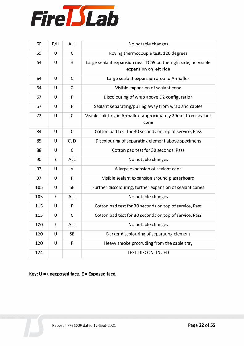
Key: U = unexposed face. E = Exposed face.
60 E/U ALL No notable changes
59 U C Roving thermocouple test, 120 degrees
64 U H Large sealant expansion near TC69 on the right side, no visible
expansion on left side
64 U C Large sealant expansion around Armaflex
64 U G Visible expansion of sealant cone
67 U F Discolouring of wrap above D2 configuration
67 U F Sealant separating/pulling away from wrap and cables
72 U C Visible splitting in Armaflex, approximately 20mm from sealant
cone
84 U C Cotton pad test for 30 seconds on top of service, Pass
85 U C, D Discolouring of separating element above specimens
88 U C Cotton pad test for 30 seconds, Pass
90 E ALL No notable changes
93 U A A large expansion of sealant cone
97 U F Visible sealant expansion around plasterboard
105 U SE Further discolouring, further expansion of sealant cones
105 E ALL No notable changes
115 U F Cotton pad test for 30 seconds on top of service, Pass
115 U C Cotton pad test for 30 seconds on top of service, Pass
120 E ALL No notable changes
120 U SE Darker discolouring of separating element
120 U F Heavy smoke protruding from the cable tray
124 TEST DISCONTINUED

Report # PF21009 dated 17-Sept-2021 Page 23 of 55
9. Separating element and main fire-stopping system
The separating element was constructed within the refractory frame, with a 140mm concrete
lintel attached, reducing the frame size to 1200mm x 1060mm. Steel Track (1.3) was fixed to
the bottom of the frame, and a Deflection Head (1.4) was fixed to the concrete lintel at 600mm
centres. Four Studs (1.2) were fixed to the frame at 50mm, 200mm, 830mm and 1150mm
from the unexposed left side of the refractory frame. The frame components were fixed
together using screws (4.1). Two sections of plasterboard were cut to 1020mm x 1200mm,
resulting in a 40mm gap between the lintel and the top edge of the plasterboard, to become
the deflection seal. One layer of plasterboard (1.5) was fixed to each face of the frame, fixed
using screws (4.2) at 300mm centres.
The Separating Element was constructed by the laboratory, in accordance with the client-
supplied diagrams. The laboratory supplied the cable tray, D1 and D2 cables. The laboratory
constructed the cable tray in accordance with the client’s description. The laboratory was not
involved in the service penetration preparation or installation.

Report # PF21009 dated 17-Sept-2021 Page 24 of 55
10. Specimens
Unexposed faced:
Exposed face:

Report # PF21009 dated 17-Sept-2021 Page 25 of 55
10.1 Specimen A

Report # PF21009 dated 17-Sept-2021 Page 26 of 55
Penetration System
A Service 32DN PVC-U Pipe with Cables
Service Details Pipe (2.9), 3 x Cable (2.1), 3 x Cable (2.2), 3 x Cable (2.3), Sealant (3.1)
Service Support Unistrut structure at 500mm and 1500mm
Aperture Size 45mm x 80mm
Annular Spacing Min: 1mm, Max: 48mm
Local Fire-stopping Protection
Application Symmetrical, capped from exposed face only
Protection Used Aperture was cut into the separating element, 2mm below the concrete lintel. 3 x Cable (2.1), 3 x Cable (2.2), 3 x Cable (2.3) were bundled together and passed into the PVC-U pipe. PVC-U pipe (2.9) was passed through the aperture, extending 500mm from both faces.
Polystyrene backing was installed in the aperture, recessed 13mm (nominal) from both faces. Sealant (3.1) was applied to the apertures, flush with the plasterboard. Once cured, a 25mm (nominal) sealant cone was applied to both faces.
An additional section of PVC-U pipe was glued to the unexposed side, extending the total length of the pipe to 2000mm.

Report # PF21009 dated 17-Sept-2021 Page 27 of 55
Test results
Structural adequacy Not applicable
Integrity No failure at 124 min
Insulation 95 min
Specimen A Thermocouples Readings

Report # PF21009 dated 17-Sept-2021 Page 28 of 55
10.2 Specimen B

Report # PF21009 dated 17-Sept-2021 Page 29 of 55
Penetration System
B Service 35mm Cable Bundle
Service Details 3 x Cable (2.1), 3 x Cable (2.2), 3 x Cable (2.3), Sealant (3.1)
Service Support Unistrut structure at 500mm
Aperture Size 50.70mm
Annular Spacing Min: 10mm, Max: 13mm
Local Fire-stopping Protection
Application Symmetrical, capped from exposed face only
Protection Used Aperture was cut into the separating element. 3 x Cable (2.1), 3 x Cable (2.2), 3 x Cable (2.3) were bundled together and passed through the aperture, extending 500mm from both faces.
Polystyrene backing was installed in the aperture, recessed 13mm (nominal) from both faces. Sealant (3.1) was applied to the apertures, flush with the plasterboard. Once cured, a 25mm (nominal) sealant cone was applied to both faces.
Test results
Structural adequacy Not applicable
Integrity No failure at 124 min
Insulation 91 min

Report # PF21009 dated 17-Sept-2021 Page 30 of 55
Specimen B Thermocouples Readings

Report # PF21009 dated 17-Sept-2021 Page 31 of 55
10.3 Specimen C

Report # PF21009 dated 17-Sept-2021 Page 32 of 55
Penetration System
C Service 3 x 20DN Copper pipes with Armaflex insulation
Service Details 3 x Armaflex (2.5), 3 x Copper Pipe (2.4), Intumescent Strap (5.2), Steel Wire clips, (4.4), Screws, (4.2), Cable Ties (4.3)
Service Support Unistrut structure at 500mm
Aperture Size 3 x 57.70mm
Annular Spacing Min: 0mm, Max: 1mm
Local Fire-stopping Protection
Application Symmetrical, capped from exposed face only
Protection Used 3 holes were cut in the separating element such that the aperture can accommodate 3 pipes. The overall dimensions of the aperture were 115mm x 110mm. A pipe (2.4) was placed into the Armaflex and passed through the aperture extending 500mm from both faces. This was repeated for all 3 pipes.
A length of Intumescent strap (5.2) was cut to wrap around each pipe one time, with approximately 20mm overlap. The strap was fixed to the separating element using steel wire clips (4.4) and screws (4.2). This was repeated for all 3 pipes. A 25mm (nominal) radius bead of sealant was applied between the intumescent strip and the separating element.

Report # PF21009 dated 17-Sept-2021 Page 33 of 55
Test results
Structural adequacy Not applicable
Integrity No failure at 124 min
Insulation 71 min
Specimen C Thermocouples Readings

Report # PF21009 dated 17-Sept-2021 Page 34 of 55
10.4 Specimen D

Report # PF21009 dated 17-Sept-2021 Page 35 of 55
Penetration System
D Service 32DN Pe-Xa Pipe
Service Details Pipe (2.6), Sealant (3.1)
Service Support Unistrut structure at 500mm and 1500mm
Aperture Size 50.79mm
Annular Spacing Min: 8mm, Max: 11mm
Local Fire-stopping Protection
Application Symmetrical, capped from exposed face only
Protection Used Aperture was cut into the separating element, then Pe-Xa pipe (2.6) was passed through the aperture, extending 500mm from the exposed face, and 2000mm from the unexposed face.
Polystyrene backing was installed in the aperture, recessed 13mm (nominal) from both faces. Sealant (3.1) was applied to the apertures, flush with the plasterboard. Once cured, a 25mm (nominal) sealant cone was applied to both faces.
Test results
Structural adequacy Not applicable
Integrity 29 min
Insulation 15 min

Report # PF21009 dated 17-Sept-2021 Page 36 of 55
Specimen D Thermocouples Readings

Report # PF21009 dated 17-Sept-2021 Page 37 of 55
10.5 Specimen E
Report # PF21009 dated 17-Sept-2021 Page 38 of 55
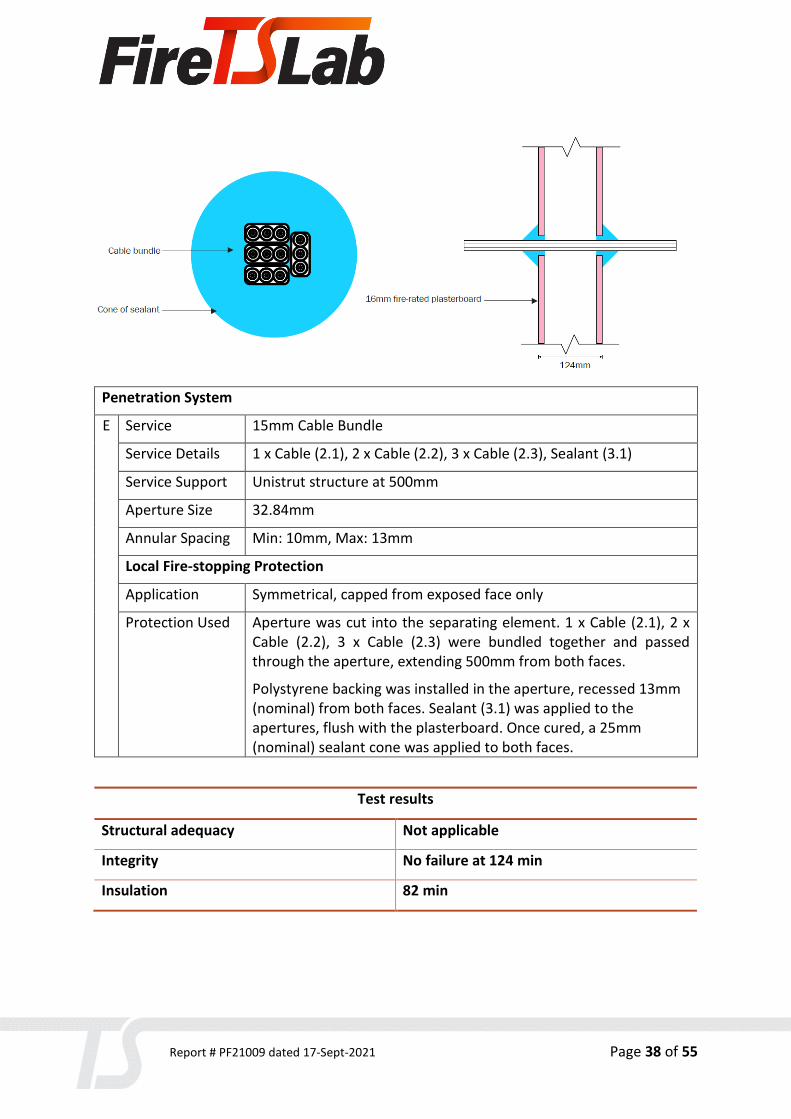
Penetration System
E Service 15mm Cable Bundle
Service Details 1 x Cable (2.1), 2 x Cable (2.2), 3 x Cable (2.3), Sealant (3.1)
Service Support Unistrut structure at 500mm
Aperture Size 32.84mm
Annular Spacing Min: 10mm, Max: 13mm
Local Fire-stopping Protection
Application Symmetrical, capped from exposed face only
Protection Used Aperture was cut into the separating element. 1 x Cable (2.1), 2 x Cable (2.2), 3 x Cable (2.3) were bundled together and passed through the aperture, extending 500mm from both faces.
Polystyrene backing was installed in the aperture, recessed 13mm (nominal) from both faces. Sealant (3.1) was applied to the apertures, flush with the plasterboard. Once cured, a 25mm (nominal) sealant cone was applied to both faces.
Test results
Structural adequacy Not applicable
Integrity No failure at 124 min
Insulation 82 min

Report # PF21009 dated 17-Sept-2021 Page 39 of 55
Specimen E Thermocouples Readings

Report # PF21009 dated 17-Sept-2021 Page 40 of 55
10.6 Specimen F
Report # PF21009 dated 17-Sept-2021 Page 41 of 55
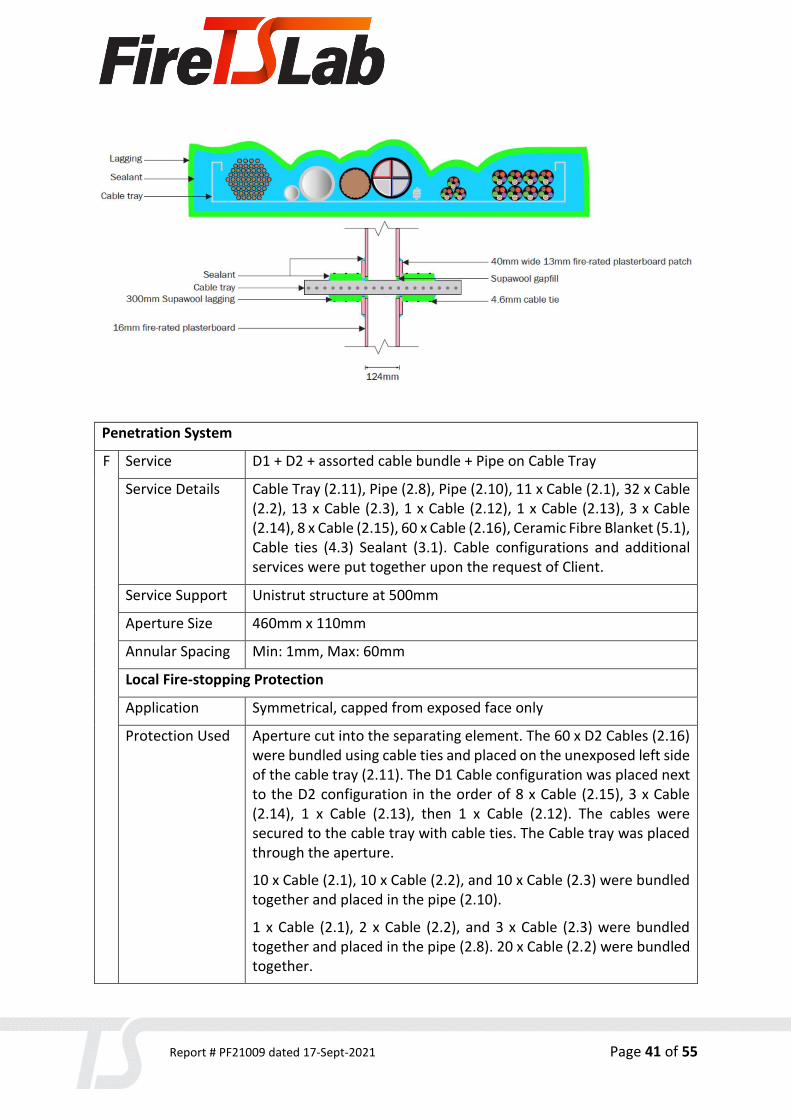
Penetration System
F Service D1 + D2 + assorted cable bundle + Pipe on Cable Tray
Service Details Cable Tray (2.11), Pipe (2.8), Pipe (2.10), 11 x Cable (2.1), 32 x Cable (2.2), 13 x Cable (2.3), 1 x Cable (2.12), 1 x Cable (2.13), 3 x Cable (2.14), 8 x Cable (2.15), 60 x Cable (2.16), Ceramic Fibre Blanket (5.1), Cable ties (4.3) Sealant (3.1). Cable configurations and additional services were put together upon the request of Client.
Service Support Unistrut structure at 500mm
Aperture Size 460mm x 110mm
Annular Spacing Min: 1mm, Max: 60mm
Local Fire-stopping Protection
Application Symmetrical, capped from exposed face only
Protection Used Aperture cut into the separating element. The 60 x D2 Cables (2.16) were bundled using cable ties and placed on the unexposed left side of the cable tray (2.11). The D1 Cable configuration was placed next to the D2 configuration in the order of 8 x Cable (2.15), 3 x Cable (2.14), 1 x Cable (2.13), then 1 x Cable (2.12). The cables were secured to the cable tray with cable ties. The Cable tray was placed through the aperture.
10 x Cable (2.1), 10 x Cable (2.2), and 10 x Cable (2.3) were bundled together and placed in the pipe (2.10).
1 x Cable (2.1), 2 x Cable (2.2), and 3 x Cable (2.3) were bundled together and placed in the pipe (2.8). 20 x Cable (2.2) were bundled together.

Report # PF21009 dated 17-Sept-2021 Page 42 of 55
Sections of the separating element were cut to accommodate the additional pipes and cable bundle. The bundle was placed between the D1 and D2 configurations on the cable tray. The pipe (2.8) was placed on top of the D1 configuration between the 8 x Cable (2.15) and the 3 x Cable (2.14). The pipe (2.10) was placed between the D1 and D2 configurations on top of the additional cable bundle. The additional pipes and cable bundle extended 500mm from both faces.
Sections of ceramic fibre blanket (5.1) were cut and pushed into the aperture gaps around the perimeter of the cable bundle. An additional section of plasterboard was cut to follow the profile of the cable tray and was fixed to the separating element with screws. This resulted in a maximum aperture gap of approximately 20mm, and a minimum aperture gap of 2mm. A bead of sealant was applied to the perimeter junction between the additional plasterboard and separating element plasterboard, and the ceramic fibre recess within the aperture was filled with sealant, resulting in a thickness of 30mm (nominal). Sealant was applied flush with the additional plasterboard layer. Once cured, a 25mm (nominal) radius bead of sealant was applied between the plasterboard and the cable tray around the perimeter.
The outside of the cable tray was wrapped with two and a half revolutions of ceramic fibre blanket. The end of the blanket measured 300mm from the separating element. The ceramic blanket was secured to the cable tray using cable trays (4.3). The remaining gaps between the cable tray and ceramic blanket were filled using more ceramic blanket.
A 25mm (nominal) radius bead of sealant was applied between the plasterboard and the ceramic blanket around the perimeter. The PVC pipes were extended to 2000mm from the unexposed face by gluing another length to the existing pipes.
Test results
Structural adequacy Not applicable
Integrity No failure at 124 min
Insulation 96 min

Report # PF21009 dated 17-Sept-2021 Page 43 of 55
Specimen F Thermocouples Readings

Report # PF21009 dated 17-Sept-2021 Page 44 of 55
10.7 Specimen G

Report # PF21009 dated 17-Sept-2021 Page 45 of 55
Penetration System
G Service 16DN Pe-Xa Pipe
Service Details Pipe (2.7), Sealant (3.1)
Service Support Unistrut structure at 500mm and 1500mm
Aperture Size 32.90mm
Annular Spacing Min: 8mm, Max: 9mm
Local Fire-stopping Protection
Application Symmetrical, capped from exposed face only
Protection Used Aperture was cut into the separating element, then Pe-Xa pipe (2.7) was passed through the aperture, extending 500mm from the exposed face, and 2000mm from the unexposed face
Polystyrene backing was installed in the aperture, recessed 13mm (nominal) from both faces. Sealant (3.1) was applied to the apertures, flush with the plasterboard. Once cured, a 25mm (nominal) sealant cone was applied to both faces.
Test results
Structural adequacy Not applicable
Integrity No failure at 125 min
Insulation 88 min

Report # PF21009 dated 17-Sept-2021 Page 46 of 55
Specimen G Thermocouples Readings

Report # PF21009 dated 17-Sept-2021 Page 47 of 55
10.8 Specimen H
Penetration System
H Service 40mm Deflection Head Seal
Service Details Sealant (3.1)
Service Support N/A
Aperture Size 1200mm x 40mm
Annular Spacing N/A
Local Fire-stopping Protection
Application Symmetrical
Protection Used Backing was placed on top of the deflection head to reduce the recess from 16mm to 13mm. The remaining gaps from the deflection head service penetration were packed with backing, making it flush with the rest of the deflection head seal gap. Sealant was applied to the recess, flush with the plasterboard.
Test results
Structural adequacy Not applicable
Integrity No failure at 124 min
Insulation 80 min

Report # PF21009 dated 17-Sept-2021 Page 48 of 55
Specimen H Thermocouples Readings

Report # PF21009 dated 17-Sept-2021 Page 49 of 55
11. Additional photographs
11.1 Materials used
Item 5.2

Report # PF21009 dated 17-Sept-2021 Page 50 of 55
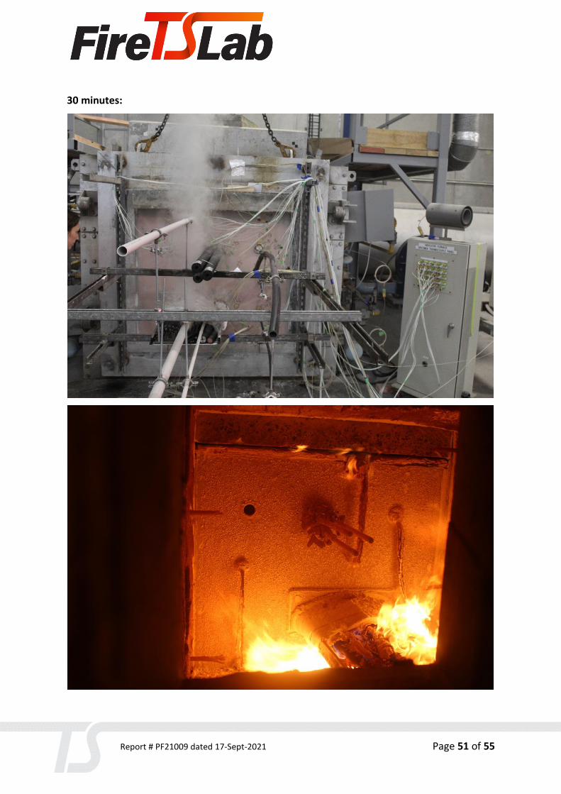
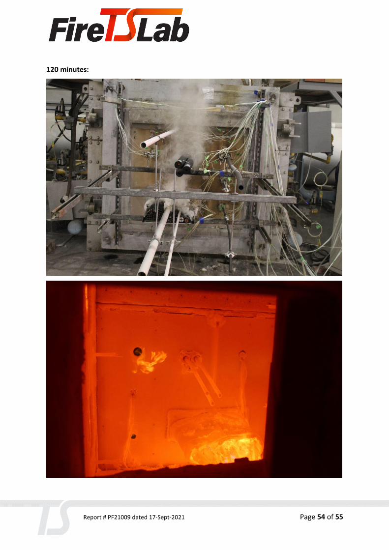
11.2 During and after the test
10 minutes:
15 minutes:
Report # PF21009 dated 17-Sept-2021 Page 51 of 55
30 minutes:

Report # PF21009 dated 17-Sept-2021 Page 52 of 55
60 minutes:

Report # PF21009 dated 17-Sept-2021 Page 53 of 55
90 minutes:
Report # PF21009 dated 17-Sept-2021 Page 54 of 55
120 minutes:

Report # PF21009 dated 17-Sept-2021 Page 55 of 55
After the test:
Top Related