


Languages
Pages
Legal


ORIGINAL RESEARCH
Finite element code-based modeling of a multi-feature isolationsystem and passive alleviation of possible inner pounding
Mohammed Ismail • Francesc Lopez-Almansa •
Amadeo Benavent-Climent • Luis G. Pujades-Beneit
Received: 8 January 2014 / Accepted: 28 July 2014
� The Author(s) 2014. This article is published with open access at Springerlink.com
Abstract The existing seismic isolation systems are based
on well-known and accepted physical principles, but they are
still having some functional drawbacks. As an attempt of
improvement, the Roll-N-Cage (RNC) isolator has been
recently proposed. It is designed to achieve a balance in
controlling isolator displacement demands and structural
accelerations. It provides in a single unit all the necessary
functions of vertical rigid support, horizontal flexibility with
enhanced stability, resistance to low service loads and minor
vibration, and hysteretic energy dissipation characteristics. It
is characterized by two unique features that are a self-braking
(buffer) and a self-recentering mechanism. This paper pre-
sents an advanced representation of the main and unique
features of the RNC isolator using an available finite element
code called SAP2000. The validity of the obtained SAP2000
model is then checked using experimental, numerical and
analytical results. Then, the paper investigates the merits and
demerits of activating the built-in buffer mechanism on both
structural pounding mitigation and isolation efficiency. The
paper addresses the problem of passive alleviation of pos-
sible inner pounding within the RNC isolator, which may
arise due to the activation of its self-braking mechanism
under sever excitations such as near-fault earthquakes. The
results show that the obtained finite element code-based
model can closely match and accurately predict the overall
behavior of the RNC isolator with effectively small errors.
Moreover, the inherent buffer mechanism of the RNC iso-
lator could mitigate or even eliminate direct structure-to-
structure pounding under severe excitation considering
limited septation gaps between adjacent structures. In addi-
tion, the increase of inherent hysteretic damping of the RNC
isolator can efficiently limit its peak displacement together
with the severity of the possibly developed inner pounding
and, therefore, alleviate or even eliminate the possibly aris-
ing negative effects of the buffer mechanism on the overall
RNC-isolated structural responses.
Keywords Seismic isolation � Adjacent structures �Self-recentering � Buffer � Hysteresis � Pounding
Introduction
Structural engineers are challenged to design economic and
visually appealing structures to safely withstand the forces
of nature such as earthquakes, which significantly affect
many areas of the world. Earthquakes generate forces as
the building inertia resists motion while the foundation
M. Ismail (&)
Structural Engineering Department, Zagazig University,
Zagazig 44519, Egypt
e-mail: [email protected];
M. Ismail
Department of Applied Mathematics III, Technical University of
Catalonia, 08034 Barcelona, Spain
F. Lopez-Almansa
Architecture Structures Department, Technical University of
Catalonia, 08028 Barcelona, Spain
e-mail: [email protected]
A. Benavent-Climent
Department of Structural Mechanics and Industrial
Constructions, Technical University of Madrid, 28006 Madrid,
Spain
e-mail: [email protected]
L. G. Pujades-Beneit
Department of Geotechnical Engineering and Geosciences,
Technical University of Catalonia, 08034 Barcelona, Spain
e-mail: [email protected]
123
Int J Adv Struct Eng (2014) 6:69
DOI 10.1007/s40091-014-0069-y
shakes with the surrounding earth. Traditionally, building
structures are designed to remain elastic during a weak
earthquake. However, for a moderately strong or strong
earthquake, the structures may behave inelastically result-
ing in cracks or residual deformations of the structures.
Although the inelastic behavior of the main structural
members provides structures with a source of energy dis-
sipation, the resulting permanent deformations and cracks
seriously affect the performance of structures and result in
costly and difficult repair work.
Along time, many innovative methods have been
developed, tested, and implemented for structural protec-
tion against earthquakes. Modern techniques for seismic
hazard mitigation in structures include seismic isolation
and energy dissipation systems. The principal function of
an energy dissipation system is to reduce the inelastic
energy dissipation demand on the framing system of a
structure (Constantinou and Symans 1993). The result is
reduced damage to the framing system. The added lateral
stiffness may shift the periods of the relevant modes of
vibration of the structure to a region of the response spectra
where the seismic demands are higher. The added lateral
strength may lead to higher component force demands,
producing premature yielding, and high story accelerations,
causing damage to contents. On the other hand, the concept
of seismic isolation is to decouple the structure from the
vibration source by means of a soft mechanical device,
usually located between the structure and its foundation.
Such an object filters the ground motion and shifts the
natural period of the structure out of the range of dominant
earthquake energy, increasing damping and limiting the
force transfer. This strategy reduces the seismic forces to or
near the elastic capacity of a structure, thus eliminating or
reducing inelastic deformation and structural damage.
A successful seismic isolation system must incorporate
seven basic elements. These are: (1) a rigid vertical
mounting to support safely the structural weight, (2) a
flexible horizontal mounting to lengthen the natural period
of the structure, (3) a damping mechanism to control the
relative deflections between the structure and the ground to
a practical design level, (4) a means of providing adequate
horizontal rigidity under low service load levels such as
wind and minor earthquakes, (5) a recentering mechanism
to re-center the isolated structure with the isolation system
after earthquake as before earthquake, (6) a buffer or
braking mechanism that imposes strict restrains on isolator
motion after a certain chosen limit to avoid structural
instability or destructive structural pounding under severe
earthquakes, and (7) the isolation system must not have any
critical inherent characteristic that may impair the isolated
structure.
A variety of isolation devices including elastomeric
bearings (with and without lead core), frictional, sliding
and roller bearings have been developed, tested and
implemented for aseismic design of structures during the
last 30 years (Kelly 1986; Skinner et al. 1993; Naeim and
Kelly 1999). In 1968, un-reinforced rubber blocks were
first implemented into a reinforced concrete building in
Macedonia but they bulged sideways under the weight the
structure and led to building bounce and rocking (Staud-
acher 1982; Jurukovski and Rakicevic 1995). The sub-
sequent development of laminated rubber bearings
improved the vertical bearing capacity but without adding a
source of damping. To combine flexibility and damping in
a single unit, the lead rubber bearing (LRB) was invented
in the 1970’s (Robinson and Tucker 1977, 1983; Tyler and
Robinson 1984). In the early 1980’s, high damping rubber
(HDR) bearings came into existence (Derham et al. 1985).
However, both LRB and HDR isolation systems still lack a
self-braking mechanism, under severe earthquakes, besides
the aptitude for low-mass structures. In addition, they
undergo bearing area reduction as displaced laterally,
which imposes restrictions on the height/width and defor-
mation/height ratios. In 1986, Al-Hussaini et al. (1994)
introduced an isolation system, namely the friction pen-
dulum system (FPS), which uses friction to dissipate the
transmitted energy to the structure and concave sliding
surfaces to provide a gravity-based recentering mechanism.
Due to the concavity of sliding surfaces, a building sup-
ported on FPS isolators exhibits vertical fluctuation and
vibrates as a simple pendulum having a constant vibration
independent of the structural mass, which represents a
severe practical difficulty that may lead to resonance fail-
ure as the FPS’s period approaches the dominant period of
the hitting earthquake (Murnal and Sinha 2004). Another
drawback is the increase of sliding friction coefficient as
sliding velocity increases as a characteristic of the interface
liner of Teflon. Such increase of friction coefficient reduces
the degree of structure–ground decoupling and results in
more force transfer.
Recently, the Roll-N-Cage (RNC) isolator has been
proposed (Ismail 2009; Ismail et al. 2008, 2009b, 2010) as
an attempt of improvement, see Figs. 1 and 2. It is a roll-
ing-based isolation system to achieve the maximum pos-
sible structure–ground decoupling and, therefore,
minimizes the seismic force transfer. It is designed to
achieve a balance in controlling isolator displacement
demands and structural accelerations. It provides in a single
unit all the necessary functions of vertical rigid support,
horizontal flexibility with enhanced stability, hysteretic
energy dissipation and resistance to minor vibration loads.
Although the rolling core is quasi-ellipsoidal, the RNC
isolator generates no vertical fluctuation of isolated struc-
ture during motion due to the inner curvatures of the upper
and lower bearing plates. Moreover, the RNC isolator is
distinguished by two unique features: (1) a self-braking
69 Page 2 of 23 Int J Adv Struct Eng (2014) 6:69
123

(buffer) mechanism to limit the isolator displacement under
severe seismic excitations to a preset value by the designer,
as shown in Fig. 3 and (2) a linear gravity-based self-
recentering mechanism that prevents residual displacement
after earthquakes, as shown in Fig. 4. Such recentering
mechanism is a result of adopting a quasi-ellipsoidal shape
of the rolling core. Besides the rolling-based motion
mechanism, which requires less lateral forces to initiate
and maintain high degree of structure–ground decoupling
compared to other motion mechanisms of the elastomeric-
based and friction-based isolation systems, the RNC iso-
lator is provided with a perfect design advantage to get the
most benefit of that rolling-based motion mechanism. Such
design advantage is the independency of both vertical
bearing mechanism and the mechanism that provides lat-
eral pre-yield stiffness against minor vibration loads. This
independency allows for accurate tuning of the initial pre-
yield stiffness to permit the commencement of the seismic
isolation process, or decoupling, just after the seismic
forces exceed the maximum limit of minor vibration loads,
contrary to the available isolation systems. The RNC iso-
lator can be available in different other forms to suit the
structure or object to be protected, see Fig. 2a and b. More
detailed description and thorough treatment of the RNC
isolator are found in Ismail (2009) reference.
This paper attempts to provide a full-featured and handy
modeling of a recently proposed multi-feature RNC isola-
tor using a commercially available finite element-based
code SAP2000 (SAP2000 documentation 2012). Such
model aims at accurately incorporating all the main and
unique features of the RNC isolator, away from mathe-
matical complications, to provide a convenient and precise
replacement of the RNC isolator in further professional
studies and research works by both practicing structural
designers as well as academic investigator. The resulting
model is then validated using different, previously
Fig. 1 The RNC isolator:
a neutral position, b vertical
cross-section at neutral position,
c to-the-left maximum
deformed position, d vertical
cross-section at to-the-left
maximum deformed position,
e metallic yield dampers and
their holders, f rolling core on
the bottom rubber plate and the
lower metallic bearing plate
Int J Adv Struct Eng (2014) 6:69 Page 3 of 23 69
123

obtained, force–displacement representations of the RNC
isolator. Then, the obtained SAP2000 model is numerically
implemented into a case study to investigate the influence
of activating its buffer mechanism on the structural
response considering severe uni and bidirectional near-
fault ground motions. Finally, the paper attempts to pas-
sively alleviate the possibly arising negative effects due to
the buffer activation of the RNC isolator.
The force–displacement relationship of the RNC
isolator
The mechanical characterization of an innovative system or
a device is often performed both experimentally and via
numerical simulation. The former approach, which is more
costly than the later one, leads directly to the physical
understanding of the system and, therefore, it can be
employed for final verification. In contrast, numerical
simulation which uses numerical methods such as finite
element method (FE) to quantitatively represent the evo-
lution of a physical system and allows for more economi-
cally exploring a large number of possible design solutions.
Using accurate models, the result of such simulations can
give a good representation of the real mechanical behavior
of the studied device or of the complex system which
comprises the device. This accuracy enables safe drawing
of proper conclusions and getting a thorough understanding
of the system.
The RNC isolator has been subjected to thorough
numerical characterization in Ismail et al. (2009b, 2010),
experimental verification in Ismail and Rodellar (2014a, b)
and full mathematical modeling in Ismail et al. (2013). The
resulting unique force–displacement relationship of the
RNC isolator is demonstrated schematically in Fig. 5. Based
on Fig. 5, the mathematical description of the total RNC
isolator’s restoring force, Fb, is obtained by superimposing
the following three individual restoring components:
1. Self-recentering component, FbR
2. Hysteretic component, FbH
3. Self-braking (buffer) component, FbB.
According to Ismail et al. (2013), the total restoring
force of the RNC isolator is expressed mathematically
according to the relationship between the actual displace-
ment of the RNC isolator and its preselected design dis-
placement xdes as:
Fb ¼FbH þ FbR if jxbj\xdes
FbH þ FbR þ FbB if jxbj[ xdes
�ð1Þ
Based on Fig. 5, the main controlling parameters of the
RNC isolator’s hysteresis loop shape are:
– Yield displacement Dy,
– Yield strength Fy of the hysteretic metallic yield
dampers,
– Maximum restoring forces (FbH þ FbR) and
(FbH þ FbR þ FbB)
(a) (b) (c)
Fig. 2 a A design of the RNC isolator for unidirectional isolation of light- to moderate-mass structures, b a design of the RNC isolator for
multidirectional isolation of heavy-mass structures, c the RNC-isolated structural model
69 Page 4 of 23 Int J Adv Struct Eng (2014) 6:69
123
– Maximum displacement Dmax,
– Elastic (pre-yield) stiffness ke defined as:Fy
Dy,
– Plastic (post-yield) stiffness kp,
– Buffer stiffness kB,
– Effective stiffness keff defined as:ðFbHþFbRÞ
xdes,
– Total effective stiffness keff�T defined as:ðFbHþFbRþFbBÞ
Dmax,
– characteristic strength Q,
– The yielding exponent n, which controls the curvature
at the hysteresis loop corners.
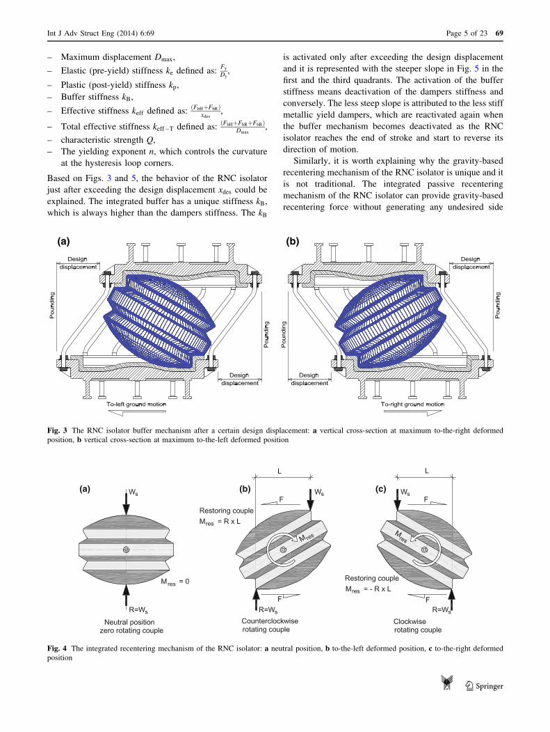
Based on Figs. 3 and 5, the behavior of the RNC isolator
just after exceeding the design displacement xdes could be
explained. The integrated buffer has a unique stiffness kB,
which is always higher than the dampers stiffness. The kB
is activated only after exceeding the design displacement
and it is represented with the steeper slope in Fig. 5 in the
first and the third quadrants. The activation of the buffer
stiffness means deactivation of the dampers stiffness and
conversely. The less steep slope is attributed to the less stiff
metallic yield dampers, which are reactivated again when
the buffer mechanism becomes deactivated as the RNC
isolator reaches the end of stroke and start to reverse its
direction of motion.
Similarly, it is worth explaining why the gravity-based
recentering mechanism of the RNC isolator is unique and it
is not traditional. The integrated passive recentering
mechanism of the RNC isolator can provide gravity-based
recentering force without generating any undesired side
(a) (b)
Fig. 3 The RNC isolator buffer mechanism after a certain design displacement: a vertical cross-section at maximum to-the-right deformed
position, b vertical cross-section at maximum to-the-left deformed position
(a) (c)(b)
Fig. 4 The integrated recentering mechanism of the RNC isolator: a neutral position, b to-the-left deformed position, c to-the-right deformed
position
Int J Adv Struct Eng (2014) 6:69 Page 5 of 23 69
123

effects. Several available traditional isolation devices [such
as springs, elliptical and friction pendulum systems (FPS)]
can provide some recentering forces but they are always
accompanied by the generation of vertical accelerations out
from the horizontal acceleration components, which leads
to additional vertical vibration of structural elements,
housed inner equipment and occupants discomfort. More-
over, the configurations that provide such recentering for-
ces in elliptical and FPS isolation systems force the isolated
structure to oscillate as a simple pendulum with a single
vibration period, which may be close to the dominant
period of the exciting earthquake causing resonance unlike
the RNC isolator. In the RNC isolator, although the rolling
core is ellipsoidal to provide adequate eccentricity for
gravity-based recentering, the upper and lower bearing
plates are provided with carefully designed inner curva-
tures (facing the rolling core) to exactly absorb any gen-
erated vertical displacement that arises from rolling of the
elliptical core. This always keeps the vertical offset
between the upper and the lower bearing plates unchanged
during the RNC isolator motion, which theoretically pre-
vents the generation of vertical motion component out from
the horizontal one, leading to a unique recentering behavior
of the RNC isolator.
Factor of safety against sliding motion of the rolling
core
The RNC isolator is configured to force only the rolling
motion of its rolling core. The relative sliding motion was
not allowed during the performed numerical and experi-
mental characterization of the device or during deriving a
full mathematical representation of its main and unique
features. Any slip between the rolling core and the upper
and lower plates is avoided, based on the following:
– The existence of two Neoprene or rubber plates
between the rolling core and both upper and lower
bearing steel plates. These rubber plates are completely
adhered to the upper and lower bearing steel plates, but
they are in direct rolling contact with the upper and
lower spherical surfaces of the rolling core. One of their
main roles is to improve the friction coefficient with the
rolling core surfaces to force only rolling motion and
prevent sliding.
– The upper and lower spherical surfaces of the rolling
core have small regular roughness to better increase the
friction coefficient with the upper and lower rubber
plates (Ismail 2009).
Hysteretic + Recentering components
Hysteretic +Recentering components
Fig. 5 Force–displacement relationship of RNC isolator
69 Page 6 of 23 Int J Adv Struct Eng (2014) 6:69
123

– The inner curvatures of the upper and lower bearing
plates (facing rolling core) were designed to prevent
vertical uplift while keeping adequate safety against
sliding (Ismail 2009).
To determine the factor of safety (FOS) against sliding of
the rolling core inside the RNC isolator at an instant of
time, let’s refer to Fig. 6 and consider only the developed
internal forces inside that core at a certain inclination angle
a, between the neutral and the farthest deformed positions.
Considering the upper contact point A between the rolling
core’s top surface and the upper bearing plate’s lower
surface, an upward reaction R1 is developed due to the
downward structural weight Ws. The reaction R1 is
decomposed into two components, normal and parallel-to-
tangent at point A, referred to as Fn1 and Fp1, respectively.
According to the design principles of the RNC isolator
(Ismail 2009), the steepest tangent slope of the inner triple
curvatures of the upper and lower bearing plates amax is
15�. Assume a static coefficient of friction between the
contact surfaces l. The parallel-to-tangent friction force
l Fn1 stabilizes the rolling core against sliding, while the
parallel-to-tangent component Fp1 is the destabilizing one
which compels sliding. Therefore, the FOS against sliding
is expressed as:
FOSsliding ¼lFn1
Fp1
¼ lR1 cosðamaxÞR1sinðamaxÞ
¼ 3:73l ð2Þ
The static coefficient of friction l is 0.74 for steel on steel
and 0.90 for steel on rubber (Grigoriev et al. 1996).
Therefore, the FOSsliding ranges from 2.76 to 3.36. Simi-
larly, the FOSsliding when considering the lower point of
contact B is high enough to avoid sliding motion of the
rolling core of the RNC isolator.
SAP2000 modeling of the RNC isolator
The objective of this Section is to develop a full-featured
and handy model of the recently proposed RNC isolator
using SAP2000 (SAP2000 documentation 2012), an
available sophisticated FE software in the area of structural
engineering. SAP2000 is an integrated stand-alone finite
element-based structural program, introduced over
30 years ago, for the analysis and design of civil structures.
SAP2000 is object-based, meaning that the models are
created using members that represent the physical reality.
Then, it automatically converts the object-based model into
an element-based model that is used for analysis. This
element-based model consists of traditional finite elements
and joints (nodes). Results of the analysis are reported back
on the object-based model. In this paper, the term ‘‘ele-
ment’’ will be used more often than ‘‘object’’, since it is
directly related to the FE analysis.
In this section, each of the three previously modeled
features of the RNC isolator (recentering, damping and
buffer) are modeled separately using one of the available
properties of the Link/Support built-in element of
SAP2000. Then, combined together to constitute a com-
prehensive model that matches the derived mathematical
model in Eq. (1) and the force–displacement relationship
shown in Fig. 5. ‘‘Modeling of the RNC isolator’s hyster-
etic damping mechanism in SAP2000’’ section models the
RNC isolator’s hysteretic damping mechanism first, as it
represents the fundamental behavior of the RNC isolator.
Then, the other two unique features of self-recentering and
self-braking mechanisms are modeled in ‘‘Modeling of the
RNC isolator’s self-recentering mechanism in SAP2000’’
and ‘‘Modeling of the RNC isolator’s self-braking (buffer)
mechanism in SAP2000’’, respectively.
(a) (b)
Fig. 6 Safety against sliding of the rolling core: a to-the-right rotation, b to-the-left rotation
Int J Adv Struct Eng (2014) 6:69 Page 7 of 23 69
123

Modeling of the RNC isolator’s hysteretic damping
mechanism in SAP2000
Although the above form of the Bouc–Wen model, which
is used to model the hysteretic behavior of the RNC iso-
lator, has been extensively used to describe nonlinear
hysteretic behaviors in seismic isolation systems, it was
proved that the parameters of that Bouc–Wen model form
are functionally redundant; that is, there exist multiple
parameter vectors that produce an identical response from a
given excitation by Constantinou and Adnane (1987) and
Ma et al. (2004). Constantinou and Adnane (1987) sug-
gested imposing the constraint Abþc ¼ 1 to reduce the model
to a formulation with well-defined properties. Ma et al.
(2004) recommended that removing this redundancy is best
achieved by setting A ¼ 1.
The hysteretic behavior of the RNC isolator can be
modeled using the Wen plasticity property in SAP2000.
Such plasticity model is based on the hysteretic behavior
proposed by Wen (1976), see Fig. 7 after eliminating the
redundant parameters (SAP2000 documentation 2012). An
independent uniaxial Wen plasticity property can be
assigned to any deformational degree of freedom, keeping
all the internal deformations independent. The hysteretic
behavior of the RNC isolator FbH can be represented by the
nonlinear force–deformation relationship of the Wen
plasticity property in SAP2000 as:
FbH ¼ ratio k d þ ð1þ ratioÞ yield z ð3Þ
where k is the elastic spring constant, yield is the yield
force, ratio is the specified ratio of post-yield stiffness to
elastic stiffness k, and z is an internal hysteretic variable.
This variable has a range of jzj � 1, with the yield surface
represented by jzj ¼ 1. The initial value of z is zero, and it
evolves according to the differential equation:
_z ¼ k
yield
_dð1� jzjexpÞ if _d z [ 0
_d otherwise
(ð4Þ
where exp is an exponent greater than or equal to unity.
Larger values of this exponent increases the sharpness of
yielding in the hysteresis loop. The practical limit for exp is
about 20.
It is worth stressing that the Wen plasticity property in
SAP2000 is based on the work of Constantinou and Adn-
ane (1987) and Ma et al. (2004). This means that the
Eq. (4) is equivalent to the standard Bouc–Wn model after
setting A ¼ 1 and b ¼ c ¼ 0:50 to eliminate redundancy of
the original model parameters (SAP2000 documentation
2012).
Modeling of the RNC isolator’s self-recentering
mechanism in SAP2000
The linear self-recentering force of the RNC isolator can be
represented simply by a horizontal linear spring property in
SAP2000, see Fig. 8a. A force equivalent to the linear
recentering force FbR of the RNC isolator can be repre-
sented by the simple force–deformation relationship for a
uniaxial linear spring property as:
FbR ¼ k d ð5Þ
where k is the spring constant and d is the deformation
across the spring.
Modeling of the RNC isolator’s self-braking (buffer)
mechanism in SAP2000
The self-braking (buffer) feature of the RNC isolator can be
modeled in SAP2000 using two Link/Support properties:
the Gap or ‘‘compression-only’’ property and the Hook or
‘‘Tension-only’’ property. Both properties can be assigned
to any deformational degree of freedom independently. The
opening or closing of a gap for one deformation does not
affect the behavior of the other deformations. Using the Gap
property, Fig. 8b, the restoring buffer component of the
RNC isolator can be represented by the following nonlinear
force–deformation relationship:
FbB ¼k ðd þ openÞ if ðd þ openÞ\0
0 otherwise
�ð6Þ
where k is the spring constant, and open is the initial gap
opening, which must be zero or positive. Using the Hook
f
d
Input:k,yield,ratio,exp,d.
Output:f.
Ground
Structure
Fig. 7 Wen plasticity property type for uniaxial deformation used in
SAP2000
69 Page 8 of 23 Int J Adv Struct Eng (2014) 6:69
123

property, Fig. 8c, the restoring buffer component of the
RNC isolator can be represented by the following nonlinear
force–deformation relationship:
FbB ¼k ðd � openÞ if ðd � openÞ[ 0
0 otherwise
�ð7Þ
where k is the spring constant, and open is the initial hook
opening, which must be zero or positive. According to Eqs.
(6) and (7), the behavior of both Gap and Hook properties
is identical except the force sign, as the Gap property
always supports compressive forces while the Hook prop-
erty supports only tensile forces. Since the buffer mecha-
nism of the RNC isolator restrains motion through
compression, Fig. 3, the concept of the Gap property
matches better than that of the buffer mechanism of the
RNC isolator.
Finally, the overall FE representation of the RNC iso-
lator using the built-in SAP2000 elements is shown in Fig.
9b. Such SAP2000 representation of the RNC isolator takes
into account the following inherent characteristics of the
device:
– Self-recentering,
– Hysteretic damping,
– Self-braking,
– Design displacement,
– Vertical rigidity,
– Horizontal flexibility,
– No uplift,
– Pre-yield stiffness.
Verification of the obtained full mathematical
and SAP2000 models for the RNC isolator
The obtained full-feature SAP2000 model of the RNC
isolator is subjected to deep numerical, analytical and
experimental validation in this section. Both numerical and
analytical verification are presented in ‘‘Numerical and
analytical verification’’, while the experimental validation
is presented in ‘‘Experimental validation’’. The discrepancy
between the measured and predicted outputs, Fm and FbH,
is then quantified using the L1 and L1-norms and the
corresponding relative errors e:
k k k
Gapelement
Open= design
displacement
Springelement
Hookelement
Ground
Structure
(a) (b) (c)
Ground
Structure
Ground
Structure
= = recentering =
Open= design
displacement
Fig. 8 a Spring property, b gap
property, c Hook property types
for uniaxial deformations used
in SAP2000
Fig. 9 Full modeling of the
RNC isolator using SAP2000’s
elements
Int J Adv Struct Eng (2014) 6:69 Page 9 of 23 69
123
jjf jj1 ¼Z Te
0
jf ðtÞjdt ð8Þ
jjf jj1 ¼ maxt2½0;Te�
jf ðtÞj ð9Þ
e1;1 ¼jjFm � Fbjj1;1jjFmjj1;1
ð10Þ
The relative error e1 quantifies the ratio of the bounded area
between the output curves to the area of the measured force
along the excitation duration Te, while e1 measures the
relative deviation of the peak force.
Numerical and analytical verification
In this section, the validity of the obtained complete
mathematical model, expressed by Eq. (1), and the full
SAP2000 model, illustrated in Fig. 9b, of the RNC isolator
are checked in five steps:
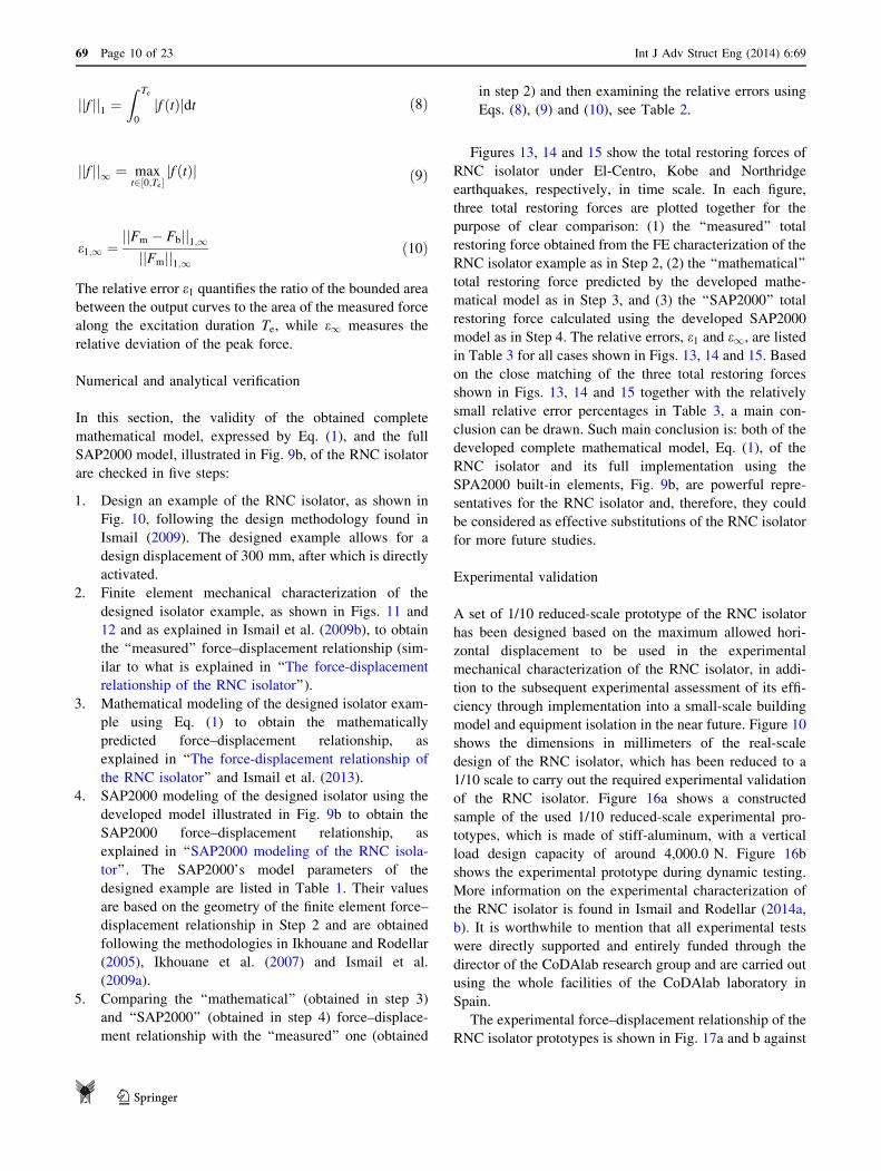
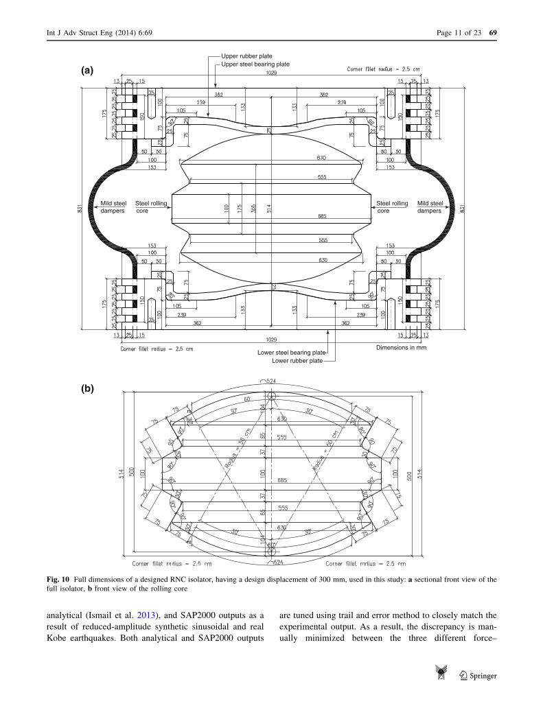
1. Design an example of the RNC isolator, as shown in
Fig. 10, following the design methodology found in
Ismail (2009). The designed example allows for a
design displacement of 300 mm, after which is directly
activated.
2. Finite element mechanical characterization of the
designed isolator example, as shown in Figs. 11 and
12 and as explained in Ismail et al. (2009b), to obtain
the ‘‘measured’’ force–displacement relationship (sim-
ilar to what is explained in ‘‘The force-displacement
relationship of the RNC isolator’’).
3. Mathematical modeling of the designed isolator exam-
ple using Eq. (1) to obtain the mathematically
predicted force–displacement relationship, as
explained in ‘‘The force-displacement relationship of
the RNC isolator’’ and Ismail et al. (2013).
4. SAP2000 modeling of the designed isolator using the
developed model illustrated in Fig. 9b to obtain the
SAP2000 force–displacement relationship, as
explained in ‘‘SAP2000 modeling of the RNC isola-
tor’’. The SAP2000’s model parameters of the
designed example are listed in Table 1. Their values
are based on the geometry of the finite element force–
displacement relationship in Step 2 and are obtained
following the methodologies in Ikhouane and Rodellar
(2005), Ikhouane et al. (2007) and Ismail et al.
(2009a).
5. Comparing the ‘‘mathematical’’ (obtained in step 3)
and ‘‘SAP2000’’ (obtained in step 4) force–displace-
ment relationship with the ‘‘measured’’ one (obtained
in step 2) and then examining the relative errors using
Eqs. (8), (9) and (10), see Table 2.
Figures 13, 14 and 15 show the total restoring forces of
RNC isolator under El-Centro, Kobe and Northridge
earthquakes, respectively, in time scale. In each figure,
three total restoring forces are plotted together for the
purpose of clear comparison: (1) the ‘‘measured’’ total
restoring force obtained from the FE characterization of the
RNC isolator example as in Step 2, (2) the ‘‘mathematical’’
total restoring force predicted by the developed mathe-
matical model as in Step 3, and (3) the ‘‘SAP2000’’ total
restoring force calculated using the developed SAP2000
model as in Step 4. The relative errors, e1 and e1, are listed
in Table 3 for all cases shown in Figs. 13, 14 and 15. Based
on the close matching of the three total restoring forces
shown in Figs. 13, 14 and 15 together with the relatively
small relative error percentages in Table 3, a main con-
clusion can be drawn. Such main conclusion is: both of the
developed complete mathematical model, Eq. (1), of the
RNC isolator and its full implementation using the
SPA2000 built-in elements, Fig. 9b, are powerful repre-
sentatives for the RNC isolator and, therefore, they could
be considered as effective substitutions of the RNC isolator
for more future studies.
Experimental validation
A set of 1/10 reduced-scale prototype of the RNC isolator
has been designed based on the maximum allowed hori-
zontal displacement to be used in the experimental
mechanical characterization of the RNC isolator, in addi-
tion to the subsequent experimental assessment of its effi-
ciency through implementation into a small-scale building
model and equipment isolation in the near future. Figure 10
shows the dimensions in millimeters of the real-scale
design of the RNC isolator, which has been reduced to a
1/10 scale to carry out the required experimental validation
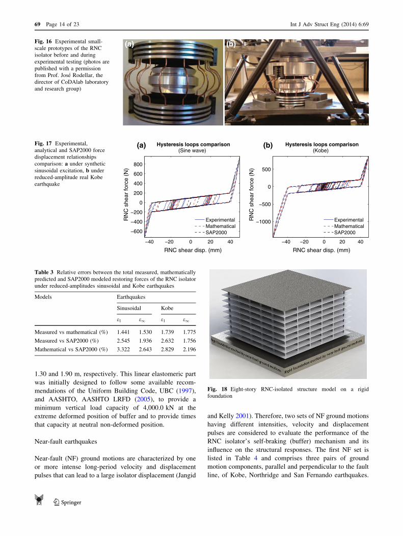
of the RNC isolator. Figure 16a shows a constructed
sample of the used 1/10 reduced-scale experimental pro-
totypes, which is made of stiff-aluminum, with a vertical
load design capacity of around 4,000.0 N. Figure 16b
shows the experimental prototype during dynamic testing.
More information on the experimental characterization of
the RNC isolator is found in Ismail and Rodellar (2014a,
b). It is worthwhile to mention that all experimental tests
were directly supported and entirely funded through the
director of the CoDAlab research group and are carried out
using the whole facilities of the CoDAlab laboratory in
Spain.
The experimental force–displacement relationship of the
RNC isolator prototypes is shown in Fig. 17a and b against
69 Page 10 of 23 Int J Adv Struct Eng (2014) 6:69
123
analytical (Ismail et al. 2013), and SAP2000 outputs as a
result of reduced-amplitude synthetic sinusoidal and real
Kobe earthquakes. Both analytical and SAP2000 outputs
are tuned using trail and error method to closely match the
experimental output. As a result, the discrepancy is man-
ually minimized between the three different force–
Upper steel bearing plateUpper rubber plate
Lower steel bearing plateLower rubber plate
Mild steeldampers
Mild steeldampers
Steel rollingcore
Steel rolling
Dimensions in mm
core
(a)
(b)
Fig. 10 Full dimensions of a designed RNC isolator, having a design displacement of 300 mm, used in this study: a sectional front view of the
full isolator, b front view of the rolling core
Int J Adv Struct Eng (2014) 6:69 Page 11 of 23 69
123

displacement relationships under each of the two consid-
ered excitations. Table 3 lists the relative errors, e1 and e1,
between the total restoring forces of the RNC isolator
under the two reduced-amplitude earthquakes considering
three outputs; the experimentally measured, the mathe-
matical, and the SAP2000 total restoring forces. Effec-
tively, the errors are small enough to lead nearly to the
same results considering any of the three RNC isolator
models. Although the errors of both experimentally mea-
sured and mathematical approaches are smaller, the use of
these two models is much more complicated and time
consuming than using the handy SAP2000 model. In other
words, regarding flexibility, versatility, computation
efforts, ease of use and wide sets of users, the SAP2000
model could represent another more practical alternative to
express the RNC isolator behavior without sacrificing or
losing the modeling accuracy. Therefore, one main con-
clusion could be drawn, which is the developed model of
the RNC isolator using SPA2000 is a powerful represen-
tative for the device in this study and further future pro-
fessional or academic research studies.
Implementation of the developed SAP2000 model
into a case study
Modeling of isolated structure
Figure 18 shows a schematic diagram of the RNC-isolated
linear multistory structure used in this study. The structure
is symmetric 3D building of five bays, each of 8.0 m span,
with double end cantilevers, each of 2.5 m length, in each
horizontal direction. It has eight floors plus the isolated
base floor with a typical story height of 3.0 m. The base
isolated structure is modeled as a shear type supported on
36 heavy load RNC isolators, Fig. 2b, one under each
column. Each floor has two lateral displacement degrees of
freedom (DOF) beside one rotational DOF around the
vertical axis. However, due to the symmetry of the 3D
structure, only one horizontal displacement DOF is con-
sidered at each floor and is excited by a single horizontal
component of earthquake ground motion in its direction.
The superstructure is considered to remain elastic during
the earthquake excitation and impact phenomenon. The
Fig. 11 Finite element meshing of the RNC isolator, neutral position
Fig. 12 Finite element meshing of the RNC isolator, to-the-left
farthest deformed position
0 2 4 6 8 10 12
-500
0
500
Time (sec)
Tot
al r
esto
ring
forc
e (k
N) Total restoring force (El-Centro)
Fig. 13 Measured vs mathematical vs SAP2000 total restoring forces of the RNC isolator due to El-Centro earthquake in time scale
69 Page 12 of 23 Int J Adv Struct Eng (2014) 6:69
123

construction material of the isolated structure is normal
weight reinforced concrete with a total material volume of
4,068.36 m3 and the structure has a total weight of
10,170.90 tons. The structural foundation is assumed to be
rigid and supported on rocky soil. The fixed-base structure
has a fundamental period of 0.436 s and modal frequencies
of 2.29, 6.80, 11.06, 14.94, 18.29, 21.02, 23.03 and
24.26 Hz for modes from one to eight, respectively. The
structural damping ratio for all modes is fixed to 2.50 % of
the critical damping.
The designed RNC isolator for this study is able to
accommodate a travel design displacement, xdes, of
53.0 cm. Just after the selected xdes, the self-braking (buf-
fer) mechanism is directly activated to stop motion over a
braking distance xbrake. The braking distance depends
mainly on pounding force intensity, FbB, and the selected
buffer stiffness kb. The designed RNC isolator is 1.20 m
high. The outer diameter of the upper and lower bearing
steel plates is 2.0 m. It is provided with eight hysteretic
mild steel dampers of the shape shown in Fig. 2b, each has
a diameter of 5.0 cm. As shown in Fig. 2b, the heavy load
form of the RNC isolator is provided with a linear hollow
elastomeric cylinder around the rolling body to represent
the main load carrying capacity, while the rolling body
itself works as a secondary support in this case. The inner
and outer diameters of the hollow elastomeric cylinder are
0 5 10 15 20 25 30 35 40-1000
-500
0
500
Time (sec)
Tot
al r
esto
ring
forc
e (k
N) Total restoring force (Kobe)
Fig. 14 Measured vs mathematical vs SAP2000 total restoring forces of the RNC isolator due to Kobe earthquake in time scale
0 5 10 15 20 25 30
-500
0
500
Time (sec)
Tot
al r
esto
ring
forc
e (k
N) Total restoring force (Northridge)
Fig. 15 Measured vs mathematical vs SAP2000 total restoring forces of the RNC isolator due to Northridge earthquake in time scale
Table 1 Numerical values of the developed SPA2000 model for the
RNC isolator
SAP2000’s full model parameter of RNC
isolator
Value (kN, mm, s)
units
Buffer stiffness 4.9033
Design displacement, Gap 300.0
Recentering stiffness 8.5808
Vertical rigidity Infinity
Horizontal freedom Pure roller
Hysteresis, k 3.4323
Hysteresis, yield 49.0333
Hysteresis, ratio 0.0500
Hysteresis, exp 2.5000
Table 2 Relative errors between the total measured, mathematically
predicted and SAP2000 modeled restoring forces of the RNC isolator
under El-Centro, Kobe and Northridge earthquakes
Models Earthquakes
El-Centro Kobe Northridge
e1 e1 e1 e1 e1 e1
Measured vs mathematical
(%)
0.24 1.49 0.68 0.64 0.20 1.12
Measured vs SAP2000 (%) 2.95 0.62 2.52 1.67 2.57 1.97
Mathematical vs SAP2000
(%)
2.71 0.86 3.22 1.02 2.77 3.12
Int J Adv Struct Eng (2014) 6:69 Page 13 of 23 69
123
1.30 and 1.90 m, respectively. This linear elastomeric part
was initially designed to follow some available recom-
mendations of the Uniform Building Code, UBC (1997),
and AASHTO, AASHTO LRFD (2005), to provide a
minimum vertical load capacity of 4,000.0 kN at the
extreme deformed position of buffer and to provide times
that capacity at neutral non-deformed position.
Near-fault earthquakes
Near-fault (NF) ground motions are characterized by one
or more intense long-period velocity and displacement
pulses that can lead to a large isolator displacement (Jangid
and Kelly 2001). Therefore, two sets of NF ground motions
having different intensities, velocity and displacement
pulses are considered to evaluate the performance of the
RNC isolator’s self-braking (buffer) mechanism and its
influence on the structural responses. The first NF set is
listed in Table 4 and comprises three pairs of ground
motion components, parallel and perpendicular to the fault
line, of Kobe, Northridge and San Fernando earthquakes.
Fig. 16 Experimental small-
scale prototypes of the RNC
isolator before and during
experimental testing (photos are
published with a permission
from Prof. Jose Rodellar, the
director of CoDAlab laboratory
and research group)
−40 −20 0 20 40
−600
−400
−200
0
200
400
600
800
RNC shear disp. (mm)
RN
C s
hear
forc
e (N
)
Hysteresis loops comparison(Sine wave)
ExperimentalMathematicalSAP2000
−40 −20 0 20 40
−1000
−500
0
500
RNC shear disp. (mm)R
NC
she
ar fo
rce
(N)
Hysteresis loops comparison(Kobe)
ExperimentalMathematicalSAP2000
(a) (b)Fig. 17 Experimental,
analytical and SAP2000 force
displacement relationships
comparison: a under synthetic
sinusoidal excitation, b under
reduced-amplitude real Kobe
earthquake
Table 3 Relative errors between the total measured, mathematically
predicted and SAP2000 modeled restoring forces of the RNC isolator
under reduced-amplitudes sinusoidal and Kobe earthquakes
Models Earthquakes
Sinusoidal Kobe
e1 e1 e1 e1
Measured vs mathematical (%) 1.441 1.530 1.739 1.775
Measured vs SAP2000 (%) 2.545 1.936 2.632 1.756
Mathematical vs SAP2000 (%) 3.322 2.643 2.829 2.196
Fig. 18 Eight-story RNC-isolated structure model on a rigid
foundation
69 Page 14 of 23 Int J Adv Struct Eng (2014) 6:69
123
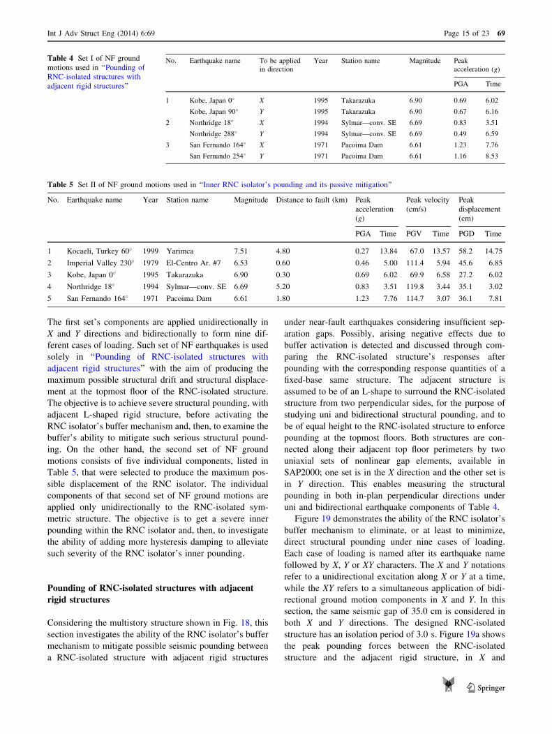
The first set’s components are applied unidirectionally in
X and Y directions and bidirectionally to form nine dif-
ferent cases of loading. Such set of NF earthquakes is used
solely in ‘‘Pounding of RNC-isolated structures with
adjacent rigid structures’’ with the aim of producing the
maximum possible structural drift and structural displace-
ment at the topmost floor of the RNC-isolated structure.
The objective is to achieve severe structural pounding, with
adjacent L-shaped rigid structure, before activating the
RNC isolator’s buffer mechanism and, then, to examine the
buffer’s ability to mitigate such serious structural pound-
ing. On the other hand, the second set of NF ground
motions consists of five individual components, listed in
Table 5, that were selected to produce the maximum pos-
sible displacement of the RNC isolator. The individual
components of that second set of NF ground motions are
applied only unidirectionally to the RNC-isolated sym-
metric structure. The objective is to get a severe inner
pounding within the RNC isolator and, then, to investigate
the ability of adding more hysteresis damping to alleviate
such severity of the RNC isolator’s inner pounding.
Pounding of RNC-isolated structures with adjacent
rigid structures
Considering the multistory structure shown in Fig. 18, this
section investigates the ability of the RNC isolator’s buffer
mechanism to mitigate possible seismic pounding between
a RNC-isolated structure with adjacent rigid structures
under near-fault earthquakes considering insufficient sep-
aration gaps. Possibly, arising negative effects due to
buffer activation is detected and discussed through com-
paring the RNC-isolated structure’s responses after
pounding with the corresponding response quantities of a
fixed-base same structure. The adjacent structure is
assumed to be of an L-shape to surround the RNC-isolated
structure from two perpendicular sides, for the purpose of
studying uni and bidirectional structural pounding, and to
be of equal height to the RNC-isolated structure to enforce
pounding at the topmost floors. Both structures are con-
nected along their adjacent top floor perimeters by two
uniaxial sets of nonlinear gap elements, available in
SAP2000; one set is in the X direction and the other set is
in Y direction. This enables measuring the structural
pounding in both in-plan perpendicular directions under
uni and bidirectional earthquake components of Table 4.
Figure 19 demonstrates the ability of the RNC isolator’s
buffer mechanism to eliminate, or at least to minimize,
direct structural pounding under nine cases of loading.
Each case of loading is named after its earthquake name
followed by X, Y or XY characters. The X and Y notations
refer to a unidirectional excitation along X or Y at a time,
while the XY refers to a simultaneous application of bidi-
rectional ground motion components in X and Y. In this
section, the same seismic gap of 35.0 cm is considered in
both X and Y directions. The designed RNC-isolated
structure has an isolation period of 3.0 s. Figure 19a shows
the peak pounding forces between the RNC-isolated
structure and the adjacent rigid structure, in X and
Table 4 Set I of NF ground
motions used in ‘‘Pounding of
RNC-isolated structures with
adjacent rigid structures’’
No. Earthquake name To be applied
in direction
Year Station name Magnitude Peak
acceleration (g)
PGA Time
1 Kobe, Japan 0� X 1995 Takarazuka 6.90 0.69 6.02
Kobe, Japan 90� Y 1995 Takarazuka 6.90 0.67 6.16
2 Northridge 18� X 1994 Sylmar—conv. SE 6.69 0.83 3.51
Northridge 288� Y 1994 Sylmar—conv. SE 6.69 0.49 6.59
3 San Fernando 164� X 1971 Pacoima Dam 6.61 1.23 7.76
San Fernando 254� Y 1971 Pacoima Dam 6.61 1.16 8.53
Table 5 Set II of NF ground motions used in ‘‘Inner RNC isolator’s pounding and its passive mitigation’’
No. Earthquake name Year Station name Magnitude Distance to fault (km) Peak
acceleration
(g)
Peak velocity
(cm/s)
Peak
displacement
(cm)
PGA Time PGV Time PGD Time
1 Kocaeli, Turkey 60� 1999 Yarimca 7.51 4.80 0.27 13.84 67.0 13.57 58.2 14.75
2 Imperial Valley 230� 1979 El-Centro Ar. #7 6.53 0.60 0.46 5.00 111.4 5.94 45.6 6.85
3 Kobe, Japan 0� 1995 Takarazuka 6.90 0.30 0.69 6.02 69.9 6.58 27.2 6.02
4 Northridge 18� 1994 Sylmar—conv. SE 6.69 5.20 0.83 3.51 119.8 3.44 35.1 3.02
5 San Fernando 164� 1971 Pacoima Dam 6.61 1.80 1.23 7.76 114.7 3.07 36.1 7.81
Int J Adv Struct Eng (2014) 6:69 Page 15 of 23 69
123

Y directions, before activating the buffer mechanism of the
RNC isolator. Such deactivation of the buffer mechanism is
guaranteed by choosing a design displacement of the RNC
isolator bigger than the actual separation seismic gap
between structures. In Fig. 19a, the RNC isolator’s design
displacement is taken 40.0 cm to ensure buffer deactiva-
tion, while it is limited to 30.0 cm in Fig. 19b to activate
the buffer mechanism before the peak bearing displace-
ment exceeds the selected seismic gap of 35.0 cm. As a
result, the influence of buffer activation on structural
pounding mitigation becomes obvious through comparing
both Fig. 19a and b.
Figure 19a shows that structural pounding has devel-
oped under six cases of loading with a maximum intensity
of 3.70 � 105 kN in Y direction under the unidirectional Y
component of the Northridge earthquake in the absence of
the buffer mechanism. On the other hand, Fig. 19b shows
that the buffer mechanism activation has entirely elimi-
nated direct structural pounding under four of the six cases
exhibiting pounding in Fig. 19a. The structural pounding of
the remaining two cases of loading is minimized to a
maximum intensity of 1.46 � 104 kN in X direction under
the unidirectional X component of the Northridge earth-
quake. This demonstrates significant reduction of direct
structural pounding under the same loading and structural
conditions, besides the entire pounding elimination under
two-thirds of the six cases exhibiting pounding.
The corresponding developed inner pounding within the
bounds of each RNC isolator is shown in Fig. 20 under the
same nine cases of loading. Figure 20a, which is corre-
sponding to Fig. 19a, shows zero developed inner pounding
inside the RNC isolator as a result of buffer deactivation.
This is attributed to the selected relatively high design
displacement of the RNC isolator of 40.0 cm, which must
be exceeded to generate inner pounding inside the RNC
isolator, what seems practically impossible under a seismic
gap of 35.0 cm with a rigid structure. Contrarily, Fig. 20b,
which corresponds to Fig. 19b, shows a developed inner
pounding within the RNC isolator due to buffer activation.
Although the peak inner RNC isolator’s pounding might be
comparable to the values of Fig. 19a of peak structural
pounding, the activation of the RNC isolator’s buffer offers
more important advantages. For example, it is not only able
to reduce or even cause structural pounding not to happen
Kobe−X Kobe−Y Kobe−XY Northridge−X Northridge−Y Northridge−XY S.Fernando−X S.Fernando−Y S.Fernando−XY0
1
2
3
4x 10
5
Peak structure pounding at the topmost floor level (buffer is NOT activeated)
Structure pounding before activating buffer
RNC-Isolated (buffer is NOT activated, i.e. design displacement of the isolator is bigger than the seismic gap), T1 = 3.0 sec
RNC-Isolated (buffer is activated, i.e. design displacement of the isolator is less than the seismic gap), T1 = 3.0 sec
Seismic gap = 35 cm, RNC design displacement = 40 cm
Exciting earthquakes (unidirectional and bidirectional)
Str
uctu
re P
ound
ing
(kN
)
Pounding in X directionPounding in Y direction
Kobe X Kobe Y Kobe XY Northridge X Northridge Y Northridge XY SanFernando X SanFernando YSanFernando XY0
1
2
3
4x 10
5
Peak structure pounding at the topmost floor level (buffer is activated)
Seismic gap = 35 cm, RNC design displacement = 30 cm
Exciting earthquakes (unidirectional and bidirectional)
Str
uctu
re P
ound
ing
(kN
)
Pounding in X directionPounding in Y direction
Structure pounding after activating buffer
(a)
(b)
Fig. 19 Peak structure pounding with adjacent structures at the topmost floors in X and Y directions under uni and bidirectional near-fault ground
motions: a buffer mechanism is not activated, b buffer mechanism is activated
69 Page 16 of 23 Int J Adv Struct Eng (2014) 6:69
123

but it also distributes pounding regularly on the isolated
base floor’s in-plan area and keeps pounding always within
the solid metallic body of the RNC isolator. Accordingly,
the RNC isolator’s buffer could prevent structural pound-
ing contact with no severe concentration of pounding for-
ces at a local point or zone anywhere in the RNC-isolated
structure, which is generally translated into less arising
damage and negative effects.
The corresponding effects of RNC isolator pounding on
the isolation efficiency are shown in Fig. 21 considering
the peak absolute structural acceleration at the topmost
floor as a performance measure. The peak absolute
structural accelerations of the RNC-isolated structure, with
buffer activated, is compared to those of the fixed-base
same structure. Although the peak acceleration responses
of the fixed-base structure are actually high, as in Fig. 21a,
they could be amplified remarkably if structural or RNC
isolator pounding exists. The load cases that exhibit no
pounding show minimal peak structural acceleration
responses. The behavior is dependent to the the interaction
between the ground motion characteristics and the struc-
tural characteristics. The amplified structural accelerations
due to inner RNC isolator’s pounding seem to be worse
(more amplified) under some loading cases and signifi-
cantly reduced under some other loading cases, as shown
by Fig. 21b. However, the main conclusion of this section
is that the RNC isolator could powerfully mitigate or even
eliminate direct structure-to-structure pounding, due to the
activation of its inherent buffer mechanism, under severe
NF ground motions. This could significantly reduce
structural and nonstructural damage and the possibly
needed repair works after strong earthquakes considering
insufficient separation gaps between adjacent structures.
Although, the peak structural accelerations could be
amplified under some ground motions after activating the
buffer mechanism. More future investigation may be
required to overcome the severity of buffer pounding and,
consequently, the amplification of structural acceleration
responses due to buffer pounding of the RNC isolator. The
next Section ‘‘Inner RNC isolator’s pounding and its
passive mitigation’’ presents a purely passive solution to
alleviate the inner pounding severity and, therefore,
reduce such amplification of structural acceleration
responses.
Kobe−X Kobe−Y Kobe−XY Northridge−X Northridge−Y Northridge−XY S.Fernando−X S.Fernando−Y S.Fernando−XY0
0.5
1
1.5
2
2.5
3
Peak RNC isolator inner pounding (for a single isolator)
Exciting earthquakes (unidirectional and bidirectional)
RN
C P
ound
ing
(kN
)
Pounding in X directionPounding in Y direction
Kobe X Kobe Y Kobe XY Northridge X Northridge Y Northridge XY SanFernando X SanFernando YSanFernando XY0
0.5
1
1.5
2
2.5
3x 10
4
Peak RNC isolator inner pounding (for a single isolator)
Exciting earthquakes (unidirectional and bidirectional)
RN
C P
ound
ing
(kN
)
Pounding in X directionPounding in Y direction
RNC isolator pounding before activating buffer
RNC-Isolated (buffer is NOT activated, i.e. design displacement of the isolator is bigger than the seismic gap), T1 = 3.0 sec
RNC-Isolated (buffer is activated, i.e. design displacement of the isolator is less than the seismic gap), T1 = 3.0 sec
Seismic gap = 35 cm, RNC design displacement = 40 cm
Seismic gap = 35 cm, RNC design displacement = 30 c
RNC isolator pounding after activating buffer
(a)
(b)
Fig. 20 Peak inner pounding of a RNC isolator in X and Y directions under uni and bidirectional near-fault ground motions: a buffer mechanism
is not activated, b buffer mechanism is activated
Int J Adv Struct Eng (2014) 6:69 Page 17 of 23 69
123

Inner RNC isolator’s pounding and its passive
mitigation
The RNC isolator is provided with a passive self-braking or
buffer mechanism to maintain structural stability under
severe earthquakes or to conform with limited surrounding
gaps. Under such conditions, the suspended base of the
RNC-isolated structure may arrive at the end of the isolator
design displacement, xdes, when the structure still has
considerable kinetic energy, due to high base velocity,
causing severe inner pounding within the RNC isolator
bounds. The first step to avoid or at least reduce the pos-
sible intense pounding, during preliminary design of RNC
isolator, is to select a design displacement, xdes, that
accommodates a travel distance a bit larger than that which
would occur during the design earthquakes. If the selected
xdes is not enough to alleviate pounding severity and to
conform with limited surrounding gaps, another alternative
is to be sought. This section investigates the ability of
increasing the amount of inherent hysteretic damping, of
the RNC isolator, as another possible non-expensive
alternative to achieve that targets considering rigorous
near-fault earthquakes.
Hysteretic damping estimation of the RNC isolator
The RNC isolator is provided with a set of triple-curvature
metallic yield dampers, as shown in Figs. 1 and 2, which
render the device a hysteretic behavior. Such curvatures are
designed to allow for smooth extension and contraction of
dampers during motion, provide adequate dampers’ length
for unrestrained rolling up to buffer and to reduce or avoid
stress concentrations at bends to increase the dampers
working life. So far, the selection of dampers number,
material and dimensions to provide a specific effective
damping ratio is carried out by trial and error. In this study,
eight mild steel dampers are selected, each of 5.0 cm
diameter. To estimate the provided effective damping of
the RNC isolator used in this study, it is modeled using
ADINA, a finite element analysis software (ADINA doc-
umentation 2011). Then, it is subjected to cyclic horizontal
shear displacement at different shear strain amplitudes up
to 100 % at loading frequency of 1 Hz. The resulting shear
force–displacement relationship is plotted against the shear
strain amplitudes in Fig. 22. From these hysteresis loops,
the effective damping n of the RNC isolator was calculated
using the following relationship:
Kobe−X Kobe−Y Kobe−XY Northridge−X Northridge−Y Northridge−XY S.Fernando−X S.Fernando−Y S.Fernando−XY0
20
40
60
80
Exciting earthquakes (unidirectional and bidirectional)
Pea
k ac
cel.
(m/s
ec2)
Peak acceleration in X directionPeak acceleration in Y direction
Kobe X Kobe Y Kobe XY Northridge X Northridge Y Northridge XY SanFernando X SanFernando YSanFernando XY0
20
40
60
80
Exciting earthquakes (unidirectional and bidirectional)
Pea
k ac
cel.
(m/s
ec2)
Peak acceleration in X directionPeak acceleration in Y direction
RNC-Isolated (buffer is activated, i.e. design displacement of the isolator is less than the seismic gap), T1 = 3.0 secSeismic gap = 35 cm, RNC design displacement = 30 c
Peak absolute structural acceleration
Peak absolute structural acceleration
Fixed−base case, T1 = 0.477 secSeismic gap = 35 cm
(a)
(b)
Fig. 21 Peak absolute structural acceleration in X and Y directions under uni and bidirectional near-fault ground motions: a fixed-base case,
b RNC-isolated case
69 Page 18 of 23 Int J Adv Struct Eng (2014) 6:69
123

n ¼ Aloop
2pFmaxdmax
g ð11Þ
where Fmax is the peak value of the shear force, dmax is the
peak value of the shear displacement, Aloop is the hysteresis
loop area, g is the number of metallic yield dampers.
The damping ratio is plotted as a function of the shear
strain in Fig. 23, where the damping ratio goes up rapidly
to a relatively high value of 48.76 % then remains almost
constant as the shear strain increases. The ability of this
high damping ratio, provided by the low-cost metallic yield
dampers, to limit the bearing displacement and pounding
severity is investigated herein under the NF earthquakes of
‘‘Near-fault earthquakes’’.
Influence of hysteretic damping on possible pounding
severity
Three structures are employed in the parametric study of
this section: the one described in ‘‘Modeling of isolated
structure’’ the same structure but once is 25 % lighter in
weight and the other time is 25 % heavier. This to inves-
tigate the influence of the isolated structural weight on
bearing displacement and pounding intensity. On the other
hand, to investigate the influence of the provided amount of
hysteretic damping by the RNC isolator on the bearing
displacement and consequently on pounding, three addi-
tional designs of the RNC isolator, of the form mentioned
in ‘‘Modeling of isolated structure’’, are considered. They
Fig. 22 The force–
displacement relationship of the
RNC isolator at different shear
strain amplitudes
Fig. 23 RNC isolator damping
vs shear strain
Int J Adv Struct Eng (2014) 6:69 Page 19 of 23 69
123
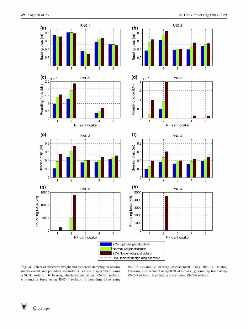
Fig. 24 Effect of structural weight and hysteretic damping on bearing
displacement and pounding intensity: a bearing displacement using
RNC-1 isolator, b bearing displacement using RNC-2 isolator,
c pounding force using RNC-1 isolator, d pounding force using
RNC-2 isolator, e bearing displacement using RNC-3 isolator,
f bearing displacement using RNC-4 isolator, g pounding force using
RNC-3 isolator, h pounding force using RNC-4 isolator
69 Page 20 of 23 Int J Adv Struct Eng (2014) 6:69
123
provide 75, 50 and 25 % less damping than the above main
designed RNC isolator, and referred to as RNC-1, RNC-2,
RNC-3, respectively, while the main RNC isolator design
of highest damping is denoted with RNC-4, i.e., the higher
the number the higher the provided damping. Then, all the
RNC-isolated structures are subjected to the five earth-
quakes of ‘‘Near-fault earthquakes’’, one at a time, and the
resulting bearing displacements as well as the pounding
forces are displayed in Fig. 24. Each earthquake is referred
to by its serial number found in the first column from left of
Table 5. All the response quantities in this section are
obtained by simulating the RNC-isolated structures using
SAP2000. The RNC isolator is represented in SAP2000
using its developed model in ‘‘SAP2000 modeling of the
RNC isolator’’. The structure floors were modeled as rigid
horizontal diaphragms while the columns are modeled with
zero axial deformation and the structural mass is lumped at
floor levels.
The bearing displacements of RNC isolators RNC-1,
RNC-2, RNC-3 and RNC-4 are displayed in Fig. 24a, b, e
and f, respectively. The corresponding pounding forces are
shown in Fig. 24c, d, g and h, respectively, considering
different structural weights and NF excitations. It seems
evident that increasing the isolator hysteretic damping
produces a decrease in the bearing displacement and con-
sequently eliminates or at least alleviates the pounding
intensity, although the heavier isolated structures are less
responsive to increasing the isolators damping. Figure 24
also demonstrates that pounding is always more intense in
the case of isolated heavy structures, even if they exhibit
closer bearing displacements to those of isolated lighter
structures. Moreover, the pounding intensity is directly
proportional to the amount of extra base displacement
beyond the bearing design displacement xdes.
Near-fault ground motions are rich in long-period fre-
quencies. This can lead to resonance conditions with
seismically isolated structures of long fundamental periods
causing undesirable higher bearing displacements. Such
resonance seems obvious in this study under the first two
earthquakes, particularly, using RNC-1 and RNC-2 isola-
tors. Although the Kocaeli and the Imperial Valley earth-
quakes have the lowest PGA in Table 5, the resulting
bearing displacements are the highest, even are higher than
those produced by San Fernando earthquake, which has the
highest PGA among the used earthquakes. This is mainly
attributed to the close structural and loading, dominant,
frequencies.
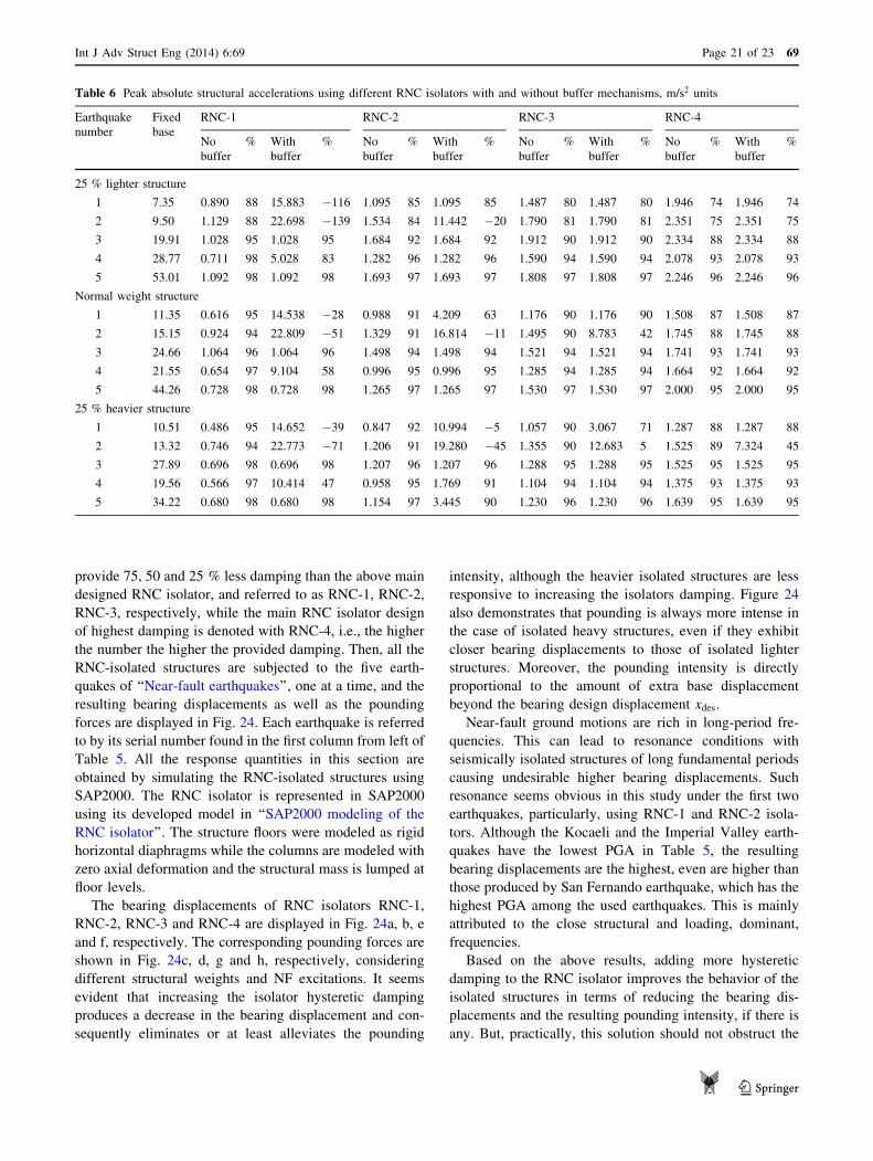
Based on the above results, adding more hysteretic
damping to the RNC isolator improves the behavior of the
isolated structures in terms of reducing the bearing dis-
placements and the resulting pounding intensity, if there is
any. But, practically, this solution should not obstruct the
Table 6 Peak absolute structural accelerations using different RNC isolators with and without buffer mechanisms, m/s2 units
Earthquake
number
Fixed
base
RNC-1 RNC-2 RNC-3 RNC-4
No
buffer
% With
buffer
% No
buffer
% With
buffer
% No
buffer
% With
buffer
% No
buffer
% With
buffer
%
25 % lighter structure
1 7.35 0.890 88 15.883 �116 1.095 85 1.095 85 1.487 80 1.487 80 1.946 74 1.946 74
2 9.50 1.129 88 22.698 �139 1.534 84 11.442 �20 1.790 81 1.790 81 2.351 75 2.351 75
3 19.91 1.028 95 1.028 95 1.684 92 1.684 92 1.912 90 1.912 90 2.334 88 2.334 88
4 28.77 0.711 98 5.028 83 1.282 96 1.282 96 1.590 94 1.590 94 2.078 93 2.078 93
5 53.01 1.092 98 1.092 98 1.693 97 1.693 97 1.808 97 1.808 97 2.246 96 2.246 96
Normal weight structure
1 11.35 0.616 95 14.538 �28 0.988 91 4.209 63 1.176 90 1.176 90 1.508 87 1.508 87
2 15.15 0.924 94 22.809 �51 1.329 91 16.814 �11 1.495 90 8.783 42 1.745 88 1.745 88
3 24.66 1.064 96 1.064 96 1.498 94 1.498 94 1.521 94 1.521 94 1.741 93 1.741 93
4 21.55 0.654 97 9.104 58 0.996 95 0.996 95 1.285 94 1.285 94 1.664 92 1.664 92
5 44.26 0.728 98 0.728 98 1.265 97 1.265 97 1.530 97 1.530 97 2.000 95 2.000 95
25 % heavier structure
1 10.51 0.486 95 14.652 �39 0.847 92 10.994 �5 1.057 90 3.067 71 1.287 88 1.287 88
2 13.32 0.746 94 22.773 �71 1.206 91 19.280 �45 1.355 90 12.683 5 1.525 89 7.324 45
3 27.89 0.696 98 0.696 98 1.207 96 1.207 96 1.288 95 1.288 95 1.525 95 1.525 95
4 19.56 0.566 97 10.414 47 0.958 95 1.769 91 1.104 94 1.104 94 1.375 93 1.375 93
5 34.22 0.680 98 0.680 98 1.154 97 3.445 90 1.230 96 1.230 96 1.639 95 1.639 95
Int J Adv Struct Eng (2014) 6:69 Page 21 of 23 69
123
isolator itself to achieve efficient isolation regarding
reducing the peak absolute structural accelerations. To
investigate that, the corresponding peak absolute structural
accelerations of the case study shown in Fig. are obtained
and listed in Table 6. The performance measure is taken as
the reduction percentage of acceleration responses. This
percentage (%) is expressed as:
% ¼ ð€xfixed�baseÞ � ð€xRNC�isolatedÞð€xfixed�baseÞ
� 100 ð12Þ
where €xfixed�base is the peak acceleration of fixed-base
structure and €xRNC�isolated is the peak acceleration of RNC-
isolated structure. The negative values of % in Table 6
indicates the undesired negative effect of pounding on
structural accelerations. From this table, the following
conclusions could be drawn:
1. Increasing the isolator hysteretic damping slightly
reduces the peak accelerations of the isolated structure.
2. At low provided damping levels, intense pounding of
an isolated structure results in structural accelerations
higher than those of its fixed-base case. This becomes
more obvious in structures with relatively light weight.
However, adding more non-expensive inherent damp-
ing can significantly improve that terrible conditions.
3. Increasing the isolator hysteretic damping can remark-
ably attenuate the undesirable increase of the structural
accelerations due to pounding.
4. The RNC isolator can achieve high levels of structural
accelerations reduction, especially under severe
ground motions.
5. Where there is no pounding, isolation of light weight
structures is less efficient under low-intensity earth-
quakes compared to heavier structures under the same
earthquakes. This isolation efficiency becomes higher
under more severe earthquakes showing similar behav-
ior to that of heavier structures under such strong
earthquakes.
Conclusions
This paper presents a full-feature representation of the Roll-
N-Cage (RNC) isolator using a commercially available
finite element code, referred to as SAP2000, to provide a
powerful and handy model of the device using a popular
software in the area of structural engineering. The devel-
oped SAP2000 model considers all the main and unique
features of the RNC isolator including self-recentering,
hysteretic damping, self-braking (buffer), design displace-
ment, vertical rigidity, horizontal flexibility, no uplift, post-
and pre-yield stiffness. The obtained model is then vali-
dated numerically, analytically and experimentally. The
discrepancy between the three representations of the RNC
isolator quantified using L1 and L1-norms with effectively
small errors. The obtained validated SAP2000 model is then
implemented into a real problem of mitigating direct
pounding of a RNC-isolated structure with a adjacent
structures, considering insufficient separation gaps in near-
fault zones, by means of the RNC isolator’s buffer mech-
anism. Finally, the paper has addressed the problem of
passive mitigation of the possible inner pounding that may
arise within the RNC isolator under severe near-fault
earthquakes. Three main conclusions are found. Firstly, the
developed SAP2000 model for the RNC isolator could be a
precise and powerful replacement of the device in more
future professional and research studies. Secondly, the
inherent buffer mechanism of the RNC isolator could suc-
cessfully reduce or even prevent direct structure-to-struc-
ture pounding under severe near-fault ground motions.
Thirdly, increasing the amount of provided non-expensive
hysteretic damping of the RNC isolator could efficiently
reduce the bearing displacement to be within affordable
design limits and, consequently, eliminates or at least
reduces pounding intensity to remarkable extents and,
therefore, reduces possible structural response amplification
due to buffer activation.
Acknowledgments The first author gratefully acknowledges the
financial support of professor Jose Rodellar, the director of CoDAlab
laboratory and research group at the Technical University of Cata-
lonia in Spain, to entirely accomplish the experimental validation of
the RNC isolator.
Open Access This article is distributed under the terms of the
Creative Commons Attribution License which permits any use, dis-
tribution, and reproduction in any medium, provided the original
author(s) and the source are credited.
References
AASHTO LRFD (2005) Bridge design specifications, SI units, 3rd
edn. American Association of State Highway and Transportation
Officials
ADINA Documentation (2011) Release 8.73. ADINA R & D Inc,
Watertown
Al-Hussaini T, Zayas V, Constantinou M (1994) Seismic isolation of
a multi-story frame structure using spherical sliding isolation
systems. In: Technical report, NCEER-94-0007. National Center
of Earthquake Engineering Research, Buffalo
Constantinou M, Adnane M (1987) Dynamics of soil-base-isolated
structure systems: evaluation of two models for yielding
systems. In: Report to NSAF, Department of Civil Engineering,
Drexel University, Philadelphia
Constantinou M, Symans M (1993) Seismic response of structures
with supplemental damping. Struct Des Tall Build 2(2):77–92
Derham C, Kelly J, Tomas A (1985) Nonlinear natural rubber
bearings for seismic isolation. Nucl Eng Des 84(3):417–428
Grigoriev I, Meilikhov E, Radzig A (1996) Handbook of physical
quantities. CRC Press, Boston
69 Page 22 of 23 Int J Adv Struct Eng (2014) 6:69
123

Ikhouane F, Rodellar J (2005) On the hysteretic Bouc–Wen model.
Part I: forced limit cycle characterization. Nonlinear Dyn
42:63–78
Ikhouane F, Manosa V, Rodellar J (2007) Dynamic properties of the
hysteretic Bouc–Wen model. Syst Control Lett 56:197–205
Ismail M (2009) An innovative isolation device for aseismic design.
PhD Thesis, Doctoral program, Earthquake engineering and
structural dynamics, vol 20, p 08, Technical University of
Catalonia, Barcelona. http://www.tdx.cat/handle/10803/6265.
Accessed 10 October 2009
Ismail M, Rodellar J (2014a) Experimental mechanical characteriza-
tion of a rolling-based seismic isolation system. In: 6th World
conference on structural control and monitoring, Barcelona,
15–17 July 2014
Ismail M, Rodellar J (2014b) A multi-purpose testing platform using
hexapod. In: 6th World conference on structural control and
monitoring, Barcelona, 15–17 July 2014
Ismail M, Rodellar J, Ikhouane F (2008) A seismic isolation system
for supported objects. Spanish patent no. P200802043, Spanish
Office of Patents and Marks
Ismail M, Ikhouane F, Rodellar J (2009a) The hysteresis Bouc–Wen
model, a survey. J Arch Comput Methods Eng 16:161–188
Ismail M, Rodellar J, Ikhouane F (2009b) Performance of structure-
equipment systems with a novel roll-n-cage isolation bearing.
Comput Struct 87:1631–1646
Ismail M, Rodellar J, Ikhouane F (2010) An innovative isolation
device for aseismic design. J Eng Struct 32:1168–1183
Ismail M, Casas J, Rodellar J (2013) Near-fault isolation of cable-
stayed bridges using RNC isolator. Eng Struct 56:327–342
Jangid R, Kelly J (2001) Base isolation for near-fault motions. Earthq
Eng Struct Dyn 30:691–707
Jurukovski D, Rakicevic Z (1995) Vibration base isolation develop-
ment and application. In: Duma (ed) 10th European conference
on earthquake engineering, Balkema, pp 667–676
Kelly J (1986) Seismic base isolation: review and bibliography. Soil
Dyn Earthq Eng 5:202–216
Ma F, Zhang H, Bockstedte A, Foliente G, Paevere P (2004)
Parameter analysis of the differential model of hysteresis. J Appl
Mech ASME 71:342–349
Murnal P, Sinha R (2004) Aseismic design of structure–equipment
systems using variable frequency pendulum isolator. Nucl Eng
Des 231:129–139
Naeim F, Kelly J (1999) Design of seismic isolated structures—from
theory to practice. Wiley, New York
Robinson W, Tucker A (1977) A lead-rubber shear damper. Bull N Z
Natl Soc Earthq Engl Natl Soc Earthq Eng 10(3):151–153
Robinson W, Tucker A (1983) Test results for lead-rubber bearings
for the William M. Clayton building, Toe Toe bridge, and
Waiotukupuna bridge. Bull N Z Natl Soc Eng 14(1):21–33
SAP2000 Documentation (2012) Release 15.1.0. Computer and
Structure Inc, Berkeley
Skinner R, Robinson W, McVerry G (1993) An introduction to
seismic isolation. Wiley, Chichester
Staudacher K (1982) Integral earthquake protection of structures IV:
full base isolation and seismic mass analogy. In: Technical
report, Eidgenossische Technische Hochschule (Zurich), Inst. fur
Baustatikund Konstruktion, Bericht 134, Birkhauser Verlag,
Basel
Tyler R, Robinson W (1984) High-strain tests on lead-rubber bearings
for earthquake loadings. Bull N Z Natl Soc Earthq Eng
17:90–105
(1997) Uniform building code. In: International conference of
building officials, California
Wen Y (1976) Method for random vibration of hysteretic systems.
J Eng Mech Div 102(EM2):246–263
Int J Adv Struct Eng (2014) 6:69 Page 23 of 23 69
123
Top Related