


Languages
Pages
Legal


© January 2018 | IJIRT | Volume 4 Issue 8 | ISSN: 2349-6002
IJIRT 145273 INTERNATIONAL JO URNAL OF INNOVATIVE RESEARCH IN TECHNOLOGY 251
Finite Element Analysis of I.C. Engine Piston –Ring
Shubham Bhawsar1, Prof K.K. Jain
2
1 Research Scholar, department of mechanical Eng. SRIT, Jabalpur (M.P)
2Professor, department of mechanical Eng. SRIT, Jabalpur (M.P)
Abstract- Piston rings have been being used for
whatever length of time that ignition motors themselves.
Regardless of this, obliviousness or lacking information
of piston rings is still every now and again clear today.
No other segment is so basic when control misfortune
and oil utilization are in question. With no other part in
the motor is the partition amongst desires and used
capital more noteworthy than when supplanting piston
rings. Very regularly, trust in piston rings endures
because of the misrepresented requests made on them.
As demonstrated in before, basic outlines of piston rings
are not examined sufficiently. Henceforth, the extent of
this venture includes following goals:To carry out the
Finite Element Analysis of piston rings subjected to
various loads acting on it. With also ,Compare the three
different material i.e. Grey Cast Iron, Aluminium Alloy
and Carbide Malleable Iron for Piston Ring using
Finite Element Analysis.
Index Terms- Piston, Piston-Ring, ANSYS, Rectangular
Cross Section and Tapered Face Cross Section piston
rings
I. INTRODUCTION
The first need for minimizing the fluid leakage
between the piston and the cylinder bore occurred in
many types of machinery, water pumps, combustion
engines, air compressors, hydraulic motors, hydraulic
pumps and others. In the early steam engines no
piston rings were used. The temperatures and the
steam pressures were not so high. Increasing power
demands required higher temperatures, which caused
stronger heat expansion of the piston material. Initial
attempt to make an extremely narrow gap resulted in
very low efficiency. The solution was found in
isolating the sealing function and making a separate
element – the piston ring – that could better conform
to the contact surface of the cylinder bore or cylinder
liner. The very first piston ring was made of rope and
assembled into a steam engine in 1774 – thermal
efficiency increased to 1.4 %. It had the sole task of
sealing off the combustion chamber, thus preventing
the combustion gases from trailing down into the
crankcase. This development increased the effective
pressure on the piston.
A piston ring is a split ring used in internal
combustion engines to fulfill three main functions:
seal the combustion chamber from transferring
gasses into the crankcase,
assure the heat flow from the piston to the
cylinder andprevent the oil, not required for
grease, from going from the crankcase to the
burning chamber and to give a uniform oil film
on the barrel bore surface.
Figure 1.1 Typical ring pack for Internal Combustion
Engine
1.1 Piston Ring Design
Piston rings are metallic seals which have the
capacity of fixing the ignition chamber from the
crankcase and assuring the stream of warmth from
the piston to the barrel. Different capacities are to
keep the oil not required for grease from going from
the crankcase to the burning chamber and to give a
uniform oil film on the barrel bore surface. Piston
rings are categorized into three basic types:
compression rings,
scraper rings and
oil control rings.
The piston rings form a ring pack, which usually
consists of 2-5 rings, including at least one
compression ring. The quantity of rings in the ring
pack relies upon the motor sort, however for the most

© January 2018 | IJIRT | Volume 4 Issue 8 | ISSN: 2349-6002
IJIRT 145273 INTERNATIONAL JO URNAL OF INNOVATIVE RESEARCH IN TECHNOLOGY 252
part includes 2-4 pressure rings and 0-3 oil control
rings (two-stroke start touched off motors don't have
an oil control ring since they have grease blended in
the fuel).
Figure 1.2 Compression ring cross sectional shape
II - LITERATURE REVIEW
The various researchers have been done research in
the field of optimization of piston rings considering
various parameters.
The piston rings are in charge of a substantial part of
the fuel utilization in overwhelming obligation diesel
motors. In this work Markus Soderfjalla et al (2017)
utilized a fast segment test fix for assessment of
piston ring contact. Various distinctive piston rings
and barrel liners are assessed in view of their grating
execution. Shear diminishing of run of the mill multi
review oil is researched by contrasting it with single
review oil.
Emil Wróblewski et al (2017) displayed the
consequences of recreation for the ventured
microgeometry piston bearing surface.Sorin-Cristian
Vlădescu et al (2017) presents an exploratory
examination into the stream conduct of grease in a
responding contact reproducing a piston ring–
chamber liner match. The point was to comprehend
the impacts of cavitation, starvation and surface, and
the association between these, so as to enhance car
motor execution.
Reducing the fuel consumption of a combustion
engine has been an important design issue. Engine
friction has to be reduced and the piston ring -
cylinder liner contact is a major source of friction.
The J. Fang et al (2016) analyses the friction and
load carrying capacity of an inclined parabolic at
piston ring. This relatively simple geometry permits
an analytical solution of the pressure distribution, the
load carrying capacity and the friction. The friction
coefficient is given as a function of twist angle, _at
width and total width. The analytical expressions
allow many thousands of calculations per second.
III-RESEARCH METHODOLOGY
3.1 Piston Ring Forces and Moments
The piston ring auxiliary movements can be isolated
into piston ring movement the transverse way, piston
ring turn, ring lift, and ring turn. These sorts of
movement result from various burdens following up
on the ring. Heaps of this kind are latency loads
emerging from the piston speeding up and
deceleration, oil film damping loads, loads
attributable to the weight distinction over the ring,
and rubbing loads from the sliding contact between
the ring and barrel liner.
Figure 3.1 Forces acting on he Piston Ring
(Handbook of Diesel Engines by Klaus Mollenhauer,
Helmut Tschöke)
3.2 Piston Ring Relationships
The ring is squeezed against the barrel divider under
a contact weight p which is represented by the
measurements and aggregate free hole of the ring and
by the modulus of flexibility of the material utilized.
The aggregate free hole is characterized as the
separation, measured along the impartial pivot,
between the finishes of a piston ring in its
uncompressed state.
Estimation of the contact pressure is tremendously
challenging. Consequently, the solution is to
calculate it from the tangential force. It can be
defined as the force which when applied tangentially
to the tops of the ring, is adequate to compress the
ring to the quantified closed gap. By solving the
© January 2018 | IJIRT | Volume 4 Issue 8 | ISSN: 2349-6002
IJIRT 145273 INTERNATIONAL JO URNAL OF INNOVATIVE RESEARCH IN TECHNOLOGY 253
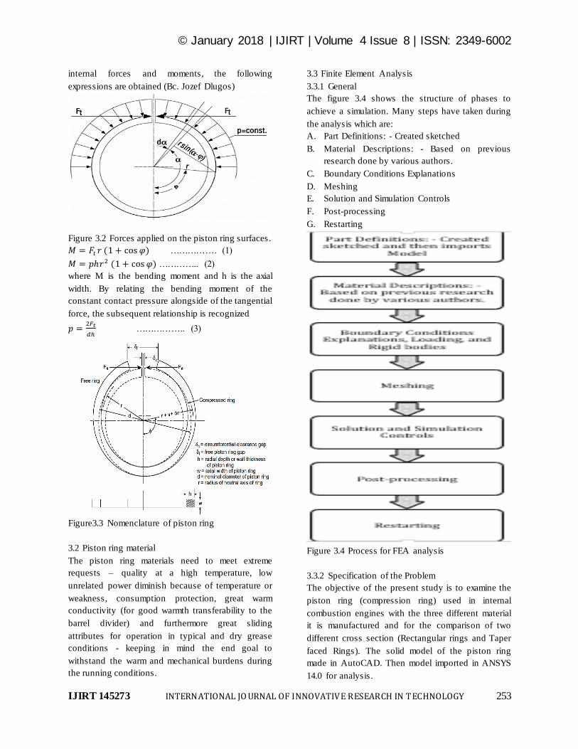
internal forces and moments, the following
expressions are obtained (Bc. Jozef Dlugos)
Figure 3.2 Forces applied on the piston ring surfaces.
……………. (1)
………….. (2)
where M is the bending moment and h is the axial
width. By relating the bending moment of the
constant contact pressure alongside of the tangential
force, the subsequent relationship is recognized
…………….. (3)
Figure3.3 Nomenclature of piston ring
3.2 Piston ring material
The piston ring materials need to meet extreme
requests – quality at a high temperature, low
unrelated power diminish because of temperature or
weakness, consumption protection, great warm
conductivity (for good warmth transferability to the
barrel divider) and furthermore great sliding
attributes for operation in typical and dry grease
conditions - keeping in mind the end goal to
withstand the warm and mechanical burdens during
the running conditions.
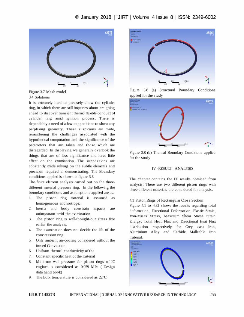
3.3 Finite Element Analysis
3.3.1 General
The figure 3.4 shows the structure of phases to
achieve a simulation. Many steps have taken during
the analysis which are:
A. Part Definitions: - Created sketched
B. Material Descriptions: - Based on previous
research done by various authors.
C. Boundary Conditions Explanations
D. Meshing
E. Solution and Simulation Controls
F. Post-processing
G. Restarting
Figure 3.4 Process for FEA analysis
3.3.2 Specification of the Problem
The objective of the present study is to examine the
piston ring (compression ring) used in internal
combustion engines with the three different material
it is manufactured and for the comparison of two
different cross section (Rectangular rings and Taper
faced Rings). The solid model of the piston ring
made in AutoCAD. Then model imported in ANSYS
14.0 for analysis.

© January 2018 | IJIRT | Volume 4 Issue 8 | ISSN: 2349-6002
IJIRT 145273 INTERNATIONAL JO URNAL OF INNOVATIVE RESEARCH IN TECHNOLOGY 254
3.3.3 Pre- processing
The Solid Modelling created using the AutoCAD and
subsequently it is imported in ANSYS workbench.
3.3.3.1 Modeling of Piston Ring
The model dimension is a model of real time design
of Piston ring used in IC engine as shown in figure
3.5. For the piston ring the outside radius R is 500
mm and minimal thickness is 2.2 mm as shown in
figure 3.5. The CAD drawing is shown in figure 3.6.
Figure 3.5 (a)
Figure 3.5 (b)
Figure 3.5 (c)
Figure 3.5 (d)
Figure 3.5 (a,b,c and d) The actual Piston Ring
considered for study.
Figure 3.6 (a) Rectangular face Piston Ring layout
Figure 3.6 (b) Tapered face Piston Ring layout
3.3.3.2 Piston Ring Materials
There are three materials used for comparison
The Table 3.1 shows the material property for all
different materials.
Table 3.3 Material properties
3.3.3 Discretization process (Meshing)
Structured meshing method done in ANSYS
Workbench used for meshing the geometry. 3840
nodes and 441 elements created. The mesh model is
presents in figure 3.4
© January 2018 | IJIRT | Volume 4 Issue 8 | ISSN: 2349-6002
IJIRT 145273 INTERNATIONAL JO URNAL OF INNOVATIVE RESEARCH IN TECHNOLOGY 255
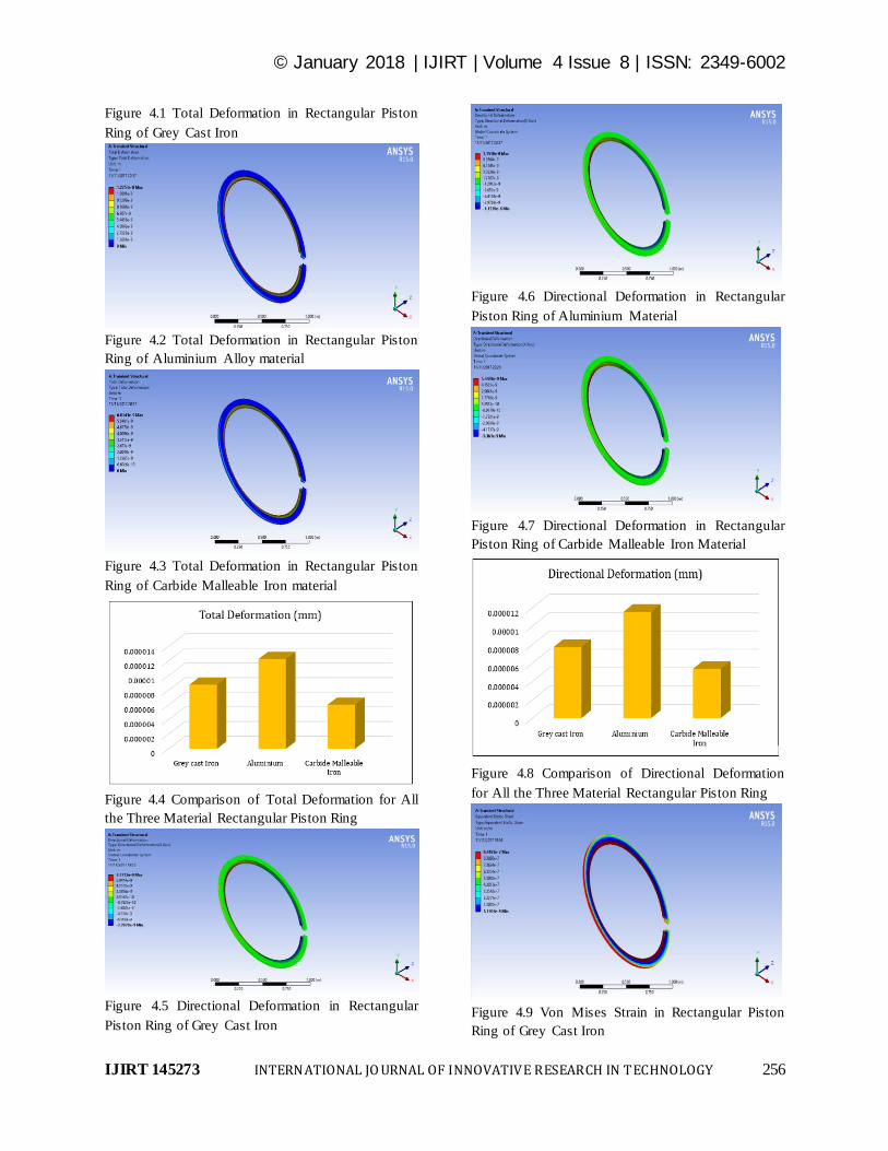
Figure 3.7 Mesh model
3.4 Solutions
It is extremely hard to precisely show the cylinder
ring, in which there are still inquiries about are going
ahead to discover transient thermo flexible conduct of
cylinder ring amid ignition process. There is
dependably a need of a few suppositions to show any
perplexing geometry. These suspicions are made,
remembering the challenges associated with the
hypothetical computation and the significance of the
parameters that are taken and those which are
disregarded. In displaying we generally overlook the
things that are of less significance and have little
effect on the examination. The suppositions are
constantly made relying on the subtle elements and
precision required in demonstrating. The Boundary
conditions applied is shown in figure 3.8
The finite element analysis carried out on the three-
different material pressure ring. In the following the
boundary conditions and assumptions applied are as:
1. The piston ring material is assumed as
homogeneous and isotropic.
2. Inertia and body constrain impacts are
unimportant amid the examination.
3. The piston ring is well-thought-out stress free
earlier the analysis.
4. The examination does not decide the life of the
compression ring.
5. Only ambient air-cooling considered without the
forced Convection.
6. Uniform thermal conductivity of the
7. Constant specific heat of the material
8. Minimum wall pressure for piston rings of IC
engines is considered as 0.059 MPa ( Design
data hand book)
9. The Bulk temperature is considered as 22°C
Figure 3.8 (a) Structural Boundary Conditions
applied for the study
Figure 3.8 (b) Thermal Boundary Conditions applied
for the study
IV -RESULT ANALYSIS
The chapter contains the FE results obtained from
analysis. There are two different piston rings with
three different materials are considered for analysis.
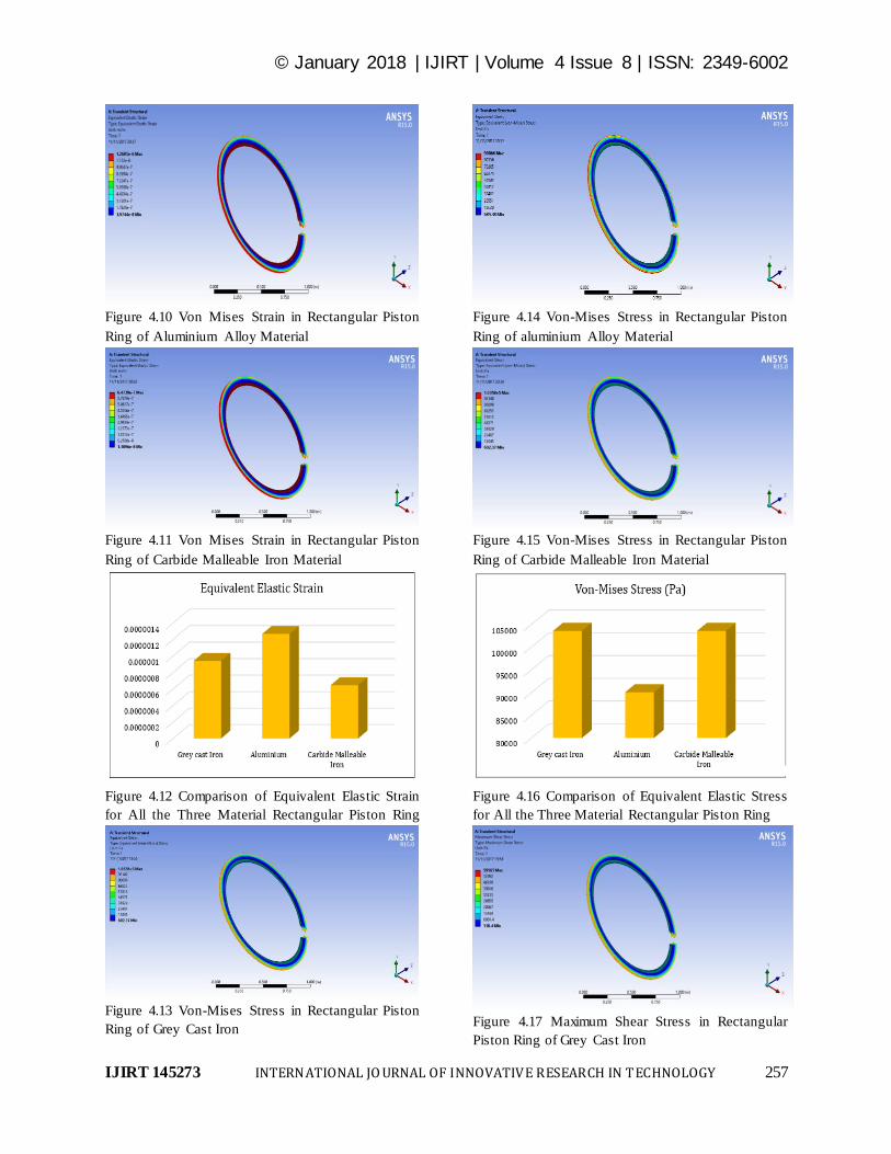
4.1 Piston Rings of Rectangular Cross Section
Figure 4.1 to 4.32 shows the results regarding total
deformation, Directional Deformation, Elastic Strain,
Von-Mises Stress, Maximum Shear Stress Strain
Energy, Total Heat Flux and Directional Heat Flux
distribution respectively for Grey cast Iron,
Aluminium Alloy and Carbide Malleable Iron
material.
© January 2018 | IJIRT | Volume 4 Issue 8 | ISSN: 2349-6002
IJIRT 145273 INTERNATIONAL JO URNAL OF INNOVATIVE RESEARCH IN TECHNOLOGY 256
Figure 4.1 Total Deformation in Rectangular Piston
Ring of Grey Cast Iron
Figure 4.2 Total Deformation in Rectangular Piston
Ring of Aluminium Alloy material
Figure 4.3 Total Deformation in Rectangular Piston
Ring of Carbide Malleable Iron material
Figure 4.4 Comparison of Total Deformation for All
the Three Material Rectangular Piston Ring
Figure 4.5 Directional Deformation in Rectangular
Piston Ring of Grey Cast Iron
Figure 4.6 Directional Deformation in Rectangular
Piston Ring of Aluminium Material
Figure 4.7 Directional Deformation in Rectangular
Piston Ring of Carbide Malleable Iron Material
Figure 4.8 Comparison of Directional Deformation
for All the Three Material Rectangular Piston Ring
Figure 4.9 Von Mises Strain in Rectangular Piston
Ring of Grey Cast Iron
© January 2018 | IJIRT | Volume 4 Issue 8 | ISSN: 2349-6002
IJIRT 145273 INTERNATIONAL JO URNAL OF INNOVATIVE RESEARCH IN TECHNOLOGY 257
Figure 4.10 Von Mises Strain in Rectangular Piston
Ring of Aluminium Alloy Material
Figure 4.11 Von Mises Strain in Rectangular Piston
Ring of Carbide Malleable Iron Material
Figure 4.12 Comparison of Equivalent Elastic Strain
for All the Three Material Rectangular Piston Ring
Figure 4.13 Von-Mises Stress in Rectangular Piston
Ring of Grey Cast Iron
Figure 4.14 Von-Mises Stress in Rectangular Piston
Ring of aluminium Alloy Material
Figure 4.15 Von-Mises Stress in Rectangular Piston
Ring of Carbide Malleable Iron Material
Figure 4.16 Comparison of Equivalent Elastic Stress
for All the Three Material Rectangular Piston Ring
Figure 4.17 Maximum Shear Stress in Rectangular
Piston Ring of Grey Cast Iron
© January 2018 | IJIRT | Volume 4 Issue 8 | ISSN: 2349-6002
IJIRT 145273 INTERNATIONAL JO URNAL OF INNOVATIVE RESEARCH IN TECHNOLOGY 258
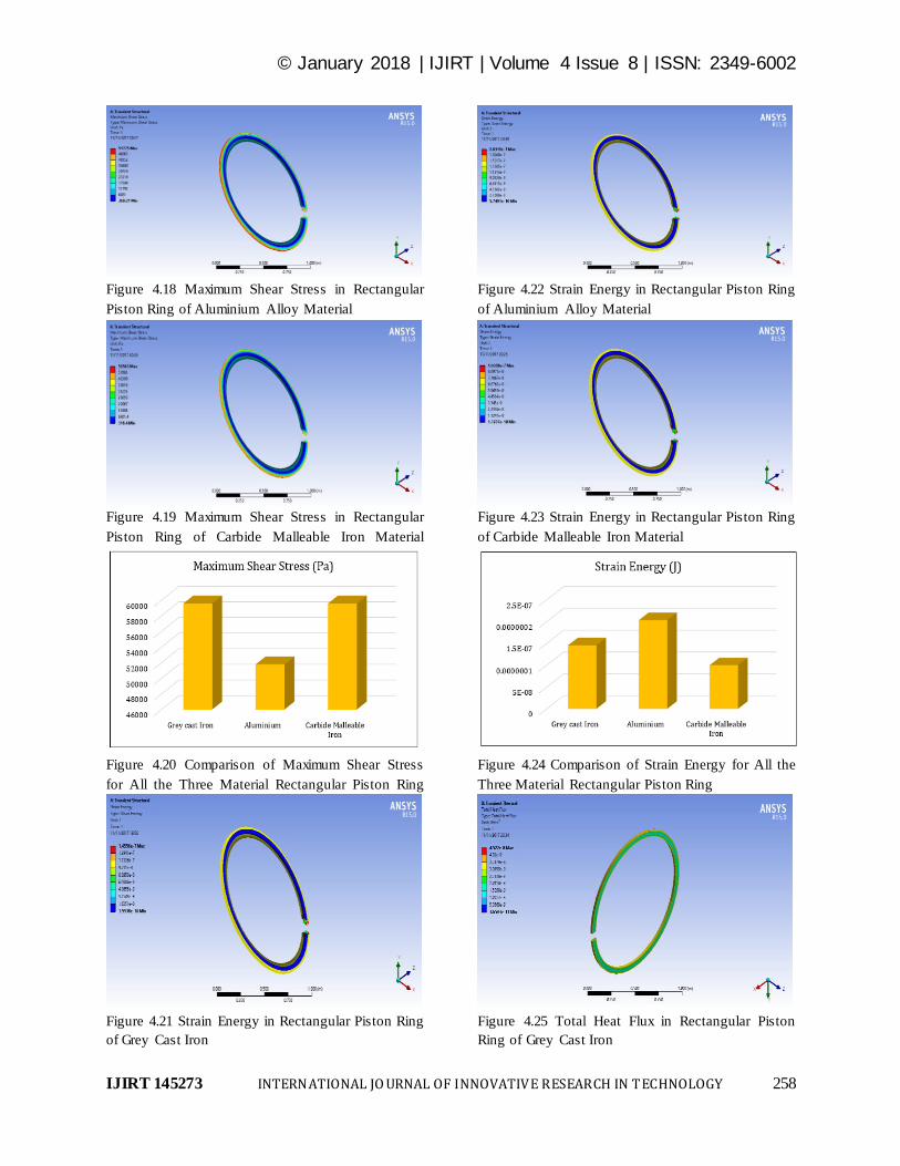
Figure 4.18 Maximum Shear Stress in Rectangular
Piston Ring of Aluminium Alloy Material
Figure 4.19 Maximum Shear Stress in Rectangular
Piston Ring of Carbide Malleable Iron Material
Figure 4.20 Comparison of Maximum Shear Stress
for All the Three Material Rectangular Piston Ring
Figure 4.21 Strain Energy in Rectangular Piston Ring
of Grey Cast Iron
Figure 4.22 Strain Energy in Rectangular Piston Ring
of Aluminium Alloy Material
Figure 4.23 Strain Energy in Rectangular Piston Ring
of Carbide Malleable Iron Material
Figure 4.24 Comparison of Strain Energy for All the
Three Material Rectangular Piston Ring
Figure 4.25 Total Heat Flux in Rectangular Piston
Ring of Grey Cast Iron
© January 2018 | IJIRT | Volume 4 Issue 8 | ISSN: 2349-6002
IJIRT 145273 INTERNATIONAL JO URNAL OF INNOVATIVE RESEARCH IN TECHNOLOGY 259
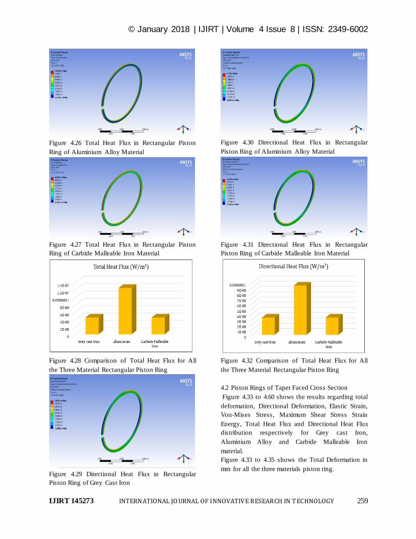
Figure 4.26 Total Heat Flux in Rectangular Piston
Ring of Aluminium Alloy Material
Figure 4.27 Total Heat Flux in Rectangular Piston
Ring of Carbide Malleable Iron Material
Figure 4.28 Comparison of Total Heat Flux for All
the Three Material Rectangular Piston Ring
Figure 4.29 Directional Heat Flux in Rectangular
Piston Ring of Grey Cast Iron
Figure 4.30 Directional Heat Flux in Rectangular
Piston Ring of Aluminium Alloy Material
Figure 4.31 Directional Heat Flux in Rectangular
Piston Ring of Carbide Malleable Iron Material
Figure 4.32 Comparison of Total Heat Flux for All
the Three Material Rectangular Piston Ring
4.2 Piston Rings of Taper Faced Cross Section
Figure 4.33 to 4.60 shows the results regarding total
deformation, Directional Deformation, Elastic Strain,
Von-Mises Stress, Maximum Shear Stress Strain
Energy, Total Heat Flux and Directional Heat Flux
distribution respectively for Grey cast Iron,
Aluminium Alloy and Carbide Malleable Iron
material.
Figure 4.33 to 4.35 shows the Total Deformation in
mm for all the three materials piston ring.
© January 2018 | IJIRT | Volume 4 Issue 8 | ISSN: 2349-6002
IJIRT 145273 INTERNATIONAL JO URNAL OF INNOVATIVE RESEARCH IN TECHNOLOGY 260
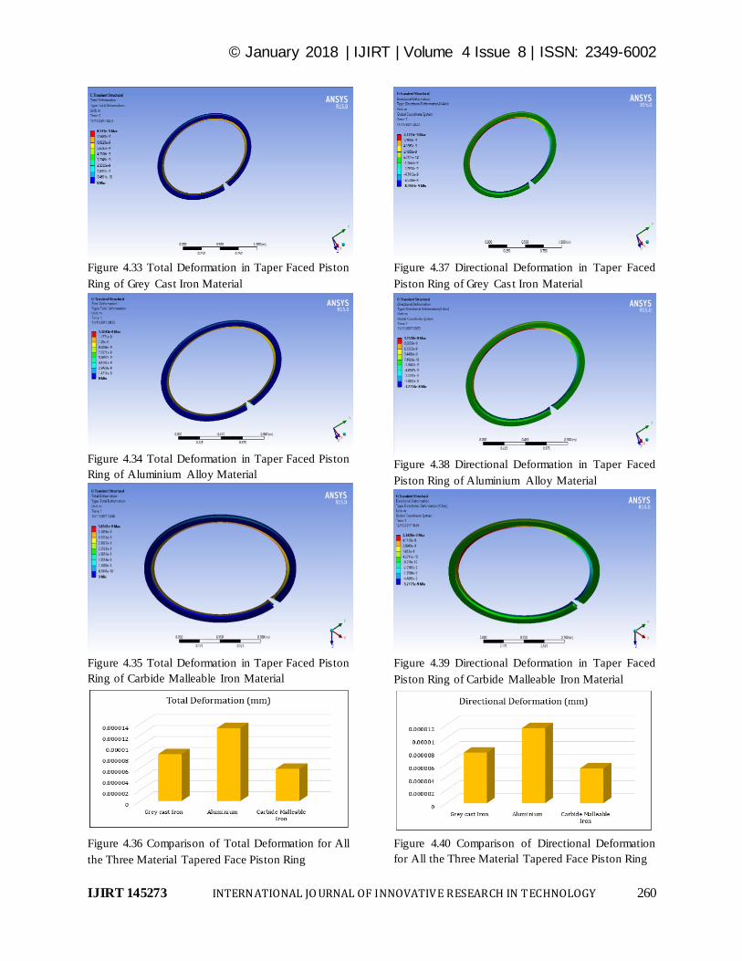
Figure 4.33 Total Deformation in Taper Faced Piston
Ring of Grey Cast Iron Material
Figure 4.34 Total Deformation in Taper Faced Piston
Ring of Aluminium Alloy Material
Figure 4.35 Total Deformation in Taper Faced Piston
Ring of Carbide Malleable Iron Material
Figure 4.36 Comparison of Total Deformation for All
the Three Material Tapered Face Piston Ring
Figure 4.37 Directional Deformation in Taper Faced
Piston Ring of Grey Cast Iron Material
Figure 4.38 Directional Deformation in Taper Faced
Piston Ring of Aluminium Alloy Material
Figure 4.39 Directional Deformation in Taper Faced
Piston Ring of Carbide Malleable Iron Material
Figure 4.40 Comparison of Directional Deformation
for All the Three Material Tapered Face Piston Ring
© January 2018 | IJIRT | Volume 4 Issue 8 | ISSN: 2349-6002
IJIRT 145273 INTERNATIONAL JO URNAL OF INNOVATIVE RESEARCH IN TECHNOLOGY 261
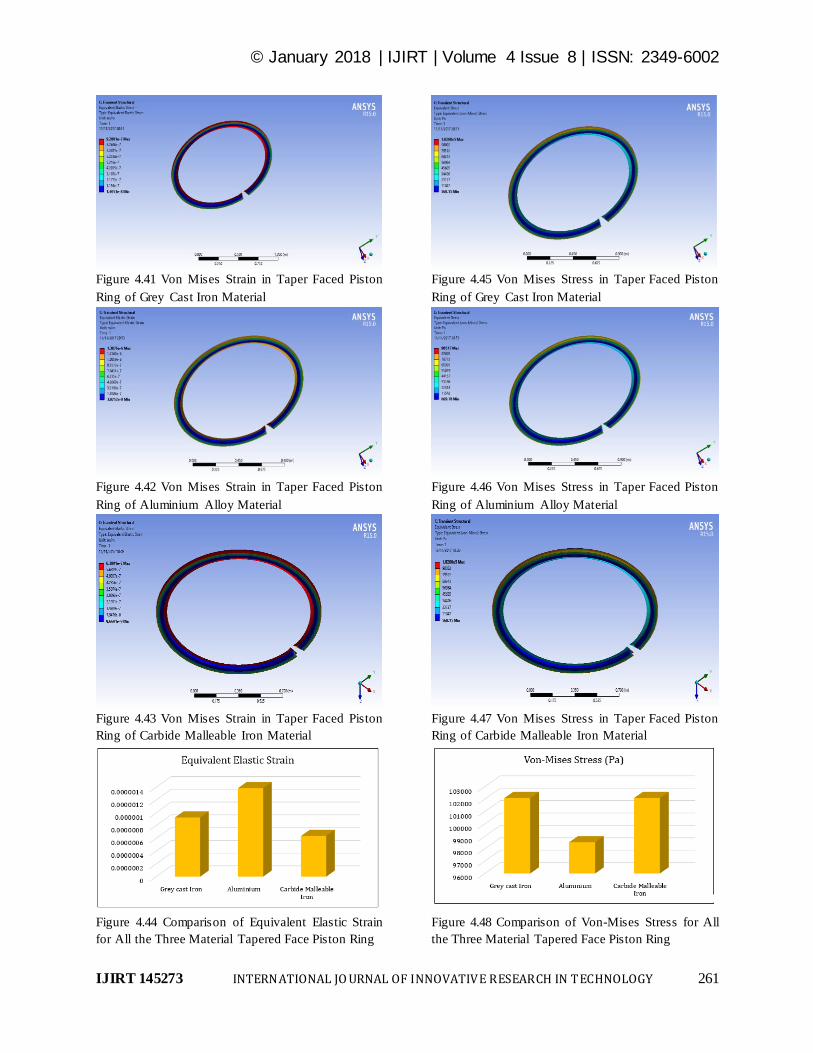
Figure 4.41 Von Mises Strain in Taper Faced Piston
Ring of Grey Cast Iron Material
Figure 4.42 Von Mises Strain in Taper Faced Piston
Ring of Aluminium Alloy Material
Figure 4.43 Von Mises Strain in Taper Faced Piston
Ring of Carbide Malleable Iron Material
Figure 4.44 Comparison of Equivalent Elastic Strain
for All the Three Material Tapered Face Piston Ring
Figure 4.45 Von Mises Stress in Taper Faced Piston
Ring of Grey Cast Iron Material
Figure 4.46 Von Mises Stress in Taper Faced Piston
Ring of Aluminium Alloy Material
Figure 4.47 Von Mises Stress in Taper Faced Piston
Ring of Carbide Malleable Iron Material
Figure 4.48 Comparison of Von-Mises Stress for All
the Three Material Tapered Face Piston Ring
© January 2018 | IJIRT | Volume 4 Issue 8 | ISSN: 2349-6002
IJIRT 145273 INTERNATIONAL JO URNAL OF INNOVATIVE RESEARCH IN TECHNOLOGY 262
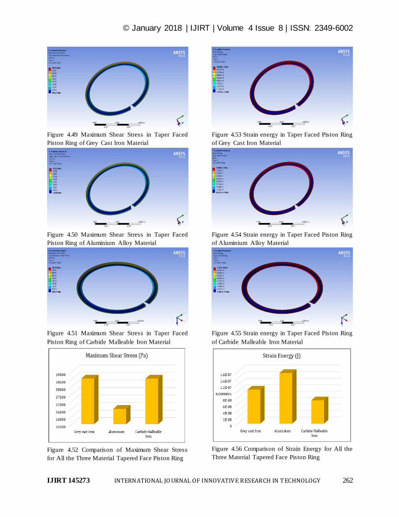
Figure 4.49 Maximum Shear Stress in Taper Faced
Piston Ring of Grey Cast Iron Material
Figure 4.50 Maximum Shear Stress in Taper Faced
Piston Ring of Aluminium Alloy Material
Figure 4.51 Maximum Shear Stress in Taper Faced
Piston Ring of Carbide Malleable Iron Material
Figure 4.52 Comparison of Maximum Shear Stress
for All the Three Material Tapered Face Piston Ring
Figure 4.53 Strain energy in Taper Faced Piston Ring
of Grey Cast Iron Material
Figure 4.54 Strain energy in Taper Faced Piston Ring
of Aluminium Alloy Material
Figure 4.55 Strain energy in Taper Faced Piston Ring
of Carbide Malleable Iron Material
Figure 4.56 Comparison of Strain Energy for All the
Three Material Tapered Face Piston Ring

© January 2018 | IJIRT | Volume 4 Issue 8 | ISSN: 2349-6002
IJIRT 145273 INTERNATIONAL JO URNAL OF INNOVATIVE RESEARCH IN TECHNOLOGY 263
Figure 4.57 Total Heat Flux in Taper Faced Piston
Ring of Grey cast Iron Material
Figure 4.58 Total Heat Flux in Taper Faced Piston
Ring of Aluminium Alloy Material
Figure 4.59 Total Heat Flux in Taper Faced Piston
Ring of Carbide Malleable Iron Material
Figure 4.60 Comparison of Total Heat Flux for All
the Three Material Tapered Face Piston Ring
Figure 4.61 Directional Heat Flux in Taper Faced
Piston Ring of Grey Cast Iron Material
Figure 4.62 Directional Heat Flux in Taper Faced
Piston Ring of Aluminium Alloy Material
Figure 4.63 Directional Heat Flux in Taper Faced
Piston Ring of Carbide Malleable Iron Material
Figure 4.60 Comparison of Directional Heat Flux for
All the Three Material Tapered Face Piston Ring

© January 2018 | IJIRT | Volume 4 Issue 8 | ISSN: 2349-6002
IJIRT 145273 INTERNATIONAL JO URNAL OF INNOVATIVE RESEARCH IN TECHNOLOGY 264
Table 4.1 Summarized results for Rectangular Cross
Section Piston Ring
Table 4.2 Summarized results for Taper Faced Cross
Section Piston Ring
V-CONCLUSION
In this work finite element analysis for static and
dynamic conditions of the engine piston ring of
different cross section with different materials was
performed. The following conclusion has been made
after the study.
The Total Deformation is about 8.748×10⁻⁶
mm for
Grey Cast Iron, 1.225×10⁻⁵
mm for Aluminium alloy
and 6.0145×10⁻⁶
mm for Carbide Malleable Iron in
case of Rectangular cross section piston ring while it
is about 8.515×10⁻⁶
mm for Grey Cast Iron,
1.3243×10⁻⁵
mm for Aluminium alloy and 5.8541×10-
6 mm for Carbide Malleable Iron in case of Tapered
face piston ring.
The Aluminium material piston ring shows the more
elastic strain compare then other two in both type of
piston rings. Carbide Malleable Iron piston ring
shows the less elastic strain in both type of piston
rings. But if compare the individual material piston
ring of same material the tapered face piston rings of
Grey Cast Iron and Carbide Malleable Cast Iron
shows the less elastic strain compare then rectangular
cross section piston rings. The condition is opposite
when we consider aluminium alloy rings.
The maximum and minimum value Von-Mises stress
or equivalent Stress for all three materials piston
rings with both cross sections are in safe limit.
The value of Shear stress for all three materials piston
rings with both cross sections are in safe limit. Thus
it can be stated that the design is safe from shear
stress point of view. The tapered face piston rings of
Grey Cast Iron and Carbide Malleable Cast Iron
shows the less shear stress compare then rectangular
cross section piston rings while it is more in
rectangular cross section rings aluminium alloy rings.
Aluminium shows the maximum strain energy while
Carbide malleable piston ring shows the minimum
strain energy.
Aluminium alloy piston ring shows the High Total
heat flux and directional heat while Both of Iron
material piston ring shows the same but lower Total
and directional heat flux in case of both Rectangular
cross section piston rings and Tapered face piston
rings. In rectangular face piston rings of Grey cast
Iron and Carbide Malleable Iron less heat flux is
generated which can be the prime factor of best
suitability, while aluminium alloy rectangular piston
rings generates high heat flux.
REFERENCES
[1] Bc. JOZEF Dlugos 2014, “Computational
Modelling Of Piston Ring Dynamics”, Brno
University of Technology.
[2] C. Kirner, J. Halbhuber, B. Uhlig, A. Oliva, S.
Graf and G. Wachtmeister, 2016 “Experimental
and simulative research advances in the piston
assembly of an internal combustion engine,”
Tribiology International
[3] C. Pettavino, N. Biboulet and A.A. Lubrecht,
Load carrying capacity and friction of a
parabolic-flat piston ring of finite width,
Tribiology International
[4] Chittenden R. J. and Priest M. Analysis of the
piston assembly, bore distortion and future
developments. In: Taylor, C.M. (Ed.). Engine
Tribology. Elsevier, 1993, Tribology series, 26,
pp. 241–270. ISBN 0-444-89755-0.

© January 2018 | IJIRT | Volume 4 Issue 8 | ISSN: 2349-6002
IJIRT 145273 INTERNATIONAL JO URNAL OF INNOVATIVE RESEARCH IN TECHNOLOGY 265
[5] Dowson, D. Piston assemblies; background and
lubrication analysis. In: Taylor, C.M. (ed.).
Engine Tribology. Elsevier, 1993, Tribology
series, 26, pp. 213–240. ISBN 0-444-89755-0.
[6] Emil Wróblewski, Antoni Iskraa, Maciej
Babiaka, 2017, “Geometrical structures of the
stepped profile bearing surface of the piston”,
TRANSCOM 2017: International scientific
conference on sustainable, modern and safe
transport.
[7] Isam Jasim Jaber and Ajeet Kumar Rai, 2014,
“Design and Analysis of I.C. Engine Piston and
Piston-Ring Using Catia and Ansys Software”,
International Journal of Mechanical Engineering
and Technology (IJMET), ISSN 0976 –
6340(Print), ISSN 0976 – 6359(Online), Volume
5, Issue 2, February (2014), pp. 64-73, ©
IAEME
[8] J. Fang, W. Ma, N. Biboulet and A.A. Lubrecht,
“Load carrying capacity and friction of an
inclined parabolic-flat piston ring”, Tribiology
International
[9] Jianliang Lin, RonghuaWei, Daniel Christopher
Bitsis, Peter M. Lee, 2016, “Development and
evaluation of low friction TiSiCN nano-
composite coatings for piston ring applications”,
Surface & Coatings Technology 298 (2016)
121–131
[10] K. Sathish Kumar, 2016, “Design and Analysis
of I.C. Engine Piston and Piston-Ring on
Composite Material Using Creo and Ansys
Software”, Journal of Engineering and Science
Vol. 01, Special Issue 01, July 2016
[11] Krisada Wannatong, Somchai Chanchaona,
Surachai Sanitjai, 2008, “Simulation algorithm
for piston ring dynamics”, Simulation Modelling
Practice and Theory 16 (2008) 127–146
[12] Markus Söderfjäll, Andreas Almqvist, Roland
Larsson, 2016, “Component test for simulation
of piston ring – Cylinder liner friction at realistic
speeds”, Tribology International 104(2016)57–
63
[13] Markus Sooderfjall, Hubert M. Herbst , Roland
Larsson , Andreas Almqvist , 2017, “Influence
on friction from piston ring design, cylinder liner
roughness and lubricant properties”, Tribology
International 116 (2017) 272–284
[14] N. Biboulet, A.A.Lubrecht, 2016, “Analytical
solution for textured piston ring – Cylinder liner
contacts (1D analysis)”, Tribology International
96(2016)269–278.
[15] O. Carvalho , M. Buciumeanu ,S. Madeira, D.
Soares , F.S. Silva , G. Miranda, 2015,
“Optimization of AlSi–CNTs functionally
graded material composites for engine piston
rings”, Materials and Design 80 (2015) 163–173
[16] Pavlo Lyubarskyy and Dirk Bartel, 2D CFD-
Model of the Piston Assembly in a Diesel Engine
for the Analysis of Piston Ring Dynamics, Mass
Transport and Friction, Tribiology International
[17] Parthiban S, Arshad Mohamed Gani P,
Vasudevan R, Naveen Kumar C, 2015, “ Design
and Performance Analysis on Piston Ring”
International Journal of Engineering Research
and General Science Volume 3, Issue 5,
September-October, 2015 ISSN 2091-2730
[18] Röhrle, M. D. Pistons for internal combustion
engines – fundamentals of piston technology,
MAHLE GmbH. Verlag Moderne Industry.
Landsberg/Lech, Germany. 1995. p. 70.
[19] Sorin-Cristian Vlădescua, Alessandra Cinieroa,
Khizer Tufail, Arup Gangopadhyay, Tom
Reddyhoff, 2017, “Looking into a laser textured
piston ring-liner contact”, Tribology
International 115 (2017) 140–153
[20] T Tian, 2001, “Dynamic behaviors of piston
rings and their practical impact. Part 2: oil
transport, friction and wear of ring/ liner
interface and the effects of piston and ring
dynamics”, Proc Instn Mech Engrs Vol 216
Downloaded from pij.sagepub.com at
COLUMBIA UNIV on February 5, 2015 Part J:
J Engineering Tribology
[21] Xingsong Wang, Xiaosong Chen, 2010,
“Measuring radial pressure distributions of
piston rings based on partial-thin-walled
cylinder”, Measurement 43 (2010) 197–203
Top Related