


Languages
Pages
Legal

FINITE ELEMENT ANALYSIS OF ELECTROMAGNET ACTUATOR FOR
NON-CONTACT MODAL TESTING
MUHAMAD KHUSAIRI BIN HASSIM
Report submitted in partial fulfilment of the requirements
For the award of degree of
Bachelor of Mechanical Engineering
Faculty of Mechanical Engineering
UNIVERSITI MALAYSIA PAHANG
MAY 2012

vii
ABSTRACT
Chatter or self-excited vibration is always occurs during high speed machining operation. This
phenomenon can reduce cutting tool life, poor surface finish on the machined component, and
the possibility of serious damage to the machine itself. Before chatter stability can be
predicted, modal testing is required to gain dynamic characteristic. This paper presents an
analysis of initial design of EMA using Finite Element Analysis (FEA). This design of initial
EMA will proper designed by using Magnetic Circuit Analysis (MCA) and Generalized
Magnetic Theory (GMT). MCA is an analytical technique used to understand the magnetic
flux characteristic of EMA, and GMT enabled predictions of the force capabilities based on
the conservation of energy principle. The FEA software that will be used was the Finite
Element Method for Magnetics (FEMM). Analysis result in the end can be displayed and
plotted including flux path and density, and various field quantities. These methods predict
that the actuator will produce sufficient force to create measurable deflection in cutting tools.

viii
ABSTRAK
Getaran “Chatter” atau getaran mekanikal sentiasa berlaku semasa operasi mesin berkelajuan
tinggi. Fenomena ini boleh mengurangkan mengurangkan hayat alat, kemasan permukaan
yang lemah pada komponen yang dimesin, dan kemungkinan mesin mengalami kerosakan
yang serius. Sebelum kestabilan getaran mekanikal ini boleh diramal, ujian mod diperlukan
untuk mendapatkan ciri-ciri dinamiknya. Kertas kerja ini membentangkan analisis reka bentuk
awal electromagnet penggerak (EMA) menggunakan Analisis Unsur Terhingga (FEA). Reka
bentuk awal EMA ini telah direka dengan menggunakan Analisis Litar Magnetik (MCA) dan
Teori Magnetik Biasa (GMT). MCA adalah teknik analisis yang digunakan untuk memahami
ciri-ciri fluks magnet EMA, dan GMT membolehkan ramalan keupayaan daya yang
berdasarkan prinsip pemuliharaan tenaga. Perisian FEA yang akan digunakan adalah Kaedah
Unsur Terhingga bagi Magnetik (FEMM). Keputusan analisis akhirnya boleh dipaparkan dan
diplotkan termasuk laluan fluks dan ketumpatan fluks dalam pelbagai cara. Kaedah-kaedah ini
meramalkan bahawa penggerak akan menghasilkan kekuatan yang cukup untuk mewujudkan
pesongan dalam alat pemotong yg boleh diukur .
ix
TABLE OF CONTENTS
Page
SUPERVISOR’S DECLARATION ii
EXAMINER’S APPROVAL DOCUMENT iii
STUDENT’S DECLARATION iv
DEDICATION v
ACKNOWLEDGEMENTS vi
ABSTRACT vii
ABSTRAK viii
TABLE OF CONTENTS ix
LIST OF TABLES xii
LIST OF FIGURES xiii
LIST OF SYMBOLS xiv
LIST OF ABBREVIATIONS xv
CHAPTER 1 INTRODUCTION AND GENERAL INFORMATION
1.1 Project Background 1
1.2 Problem Statement 2
1.3 Project Objectives 2
1.4 Project Scopes 2
CHAPTER 2 LITERITURE REVIEW
2.1 Introduction 4
2.2 High Speed Machining (HSM) 4
2.2.1 Background 5
2.2.2 Advantage of HSM 6
2.3 Chatter Vibration in Cutting
2.3.1 Background 7

x
2.4 Vibration Analysis 7
2.4.1 Types of Vibration 8
2.4.2 Vibration Analysis Method 8
2.5 Structure Analysis
2.5.1 Modal Analysis 9
2.5.1.1 Impact Hammer Modal Testing 10
2.5.1.2 Shaker Modal Testing 11
2.5.1.3 Non-contact Modal Testing 12
2.5.1.4 Electromagnet Actuator 13
2.5.1.5 Natural Frequency 14
2.5.1.6 Resonance 16
2.5.1.7 Mode 16
2.5.1.8 Damping 17
2.6 Finite Element Analysis 17
2.6.1 Modal Analysis (FEM) 18
2.6.2 Electromagnet Analysis 19
2.6.3 Simulation 19
2.6.4 Advantages of Modal Analysis 19
2.6.5 Importance of Study 20
2.7 Conclusion 20
CHAPTER 3 METHODOLOGY
3.1 Introduction 21
3.2 Flow Chart 21
3.3 Model Design 23
3.3.1 CAD Software 24
3.3.2 Finite Element Analysis 24
3.3.3 Numerical Method 24
3.3.4 Technical Assumption 24
3.3.5 Variable Parameter 25
3.3.6 Fixed Parameter 25
3.3.7 Model Design 26
3.4 Design of Experiment 27
3.4.1 Magnetostatic 28
3.4.2 ANSYS Magnetostatic Facts 29
3.5 Performing Experiment 30
3.5.1 ANSYS: Engineering Data 30
3.5.2 Experiment Procedure 31
3.5.3 Calculation of Magnetic Field 31
3.6 Model Analysis 32
3.7 Conclusion 35

xi
CHAPTER 4 RESULTS AND ANALYSIS
4.1 Introduction 36
4.2 Data Collection
4.2.1 Total Magnetic Field Intensity 37
4.2.2 Total Magnetic Flux Density 37
4.2.3 Primary Model 37
4.2.4 Secondary Model 38
4.2.5 Model from Journal 40
4.3 Analysis Data 41
4.3.1 Model Comparison 41
4.3.2 Finite Element Method for Magnetic (FEMM) 43
4.3.3 Primary Model ANSYS Workbench 44
4.3.4 Numerical Method 46
4.4 Discussion 47
4.4.1 Result comparisons 48
4.4.2 Benefits of Non-contact Modal Testing 50
4.5 Conclusion 50
CHAPTER 5 CONCLUSION
5.1 Introduction 51
5.2 Conclusions 51
5.3 Recommendations 52
REFERENCES 53
APPENDICES
A1 Recommended Electromagnet Actuator for Non-Contact
Modal Testing 56
A2 Engineering Drawing of Electromagnet Actuator (Top View) 57
A3 Engineering Drawing of Electromagnet Actuator (Front View) 58
B1 Gantt chart For Final Year Project I 60
B2 Gantt chart for Final Year Project II 61

xii
LIST OF TABLES
Table No. Page
3.1 The Variable Parameter 20
3.2 Fixed Parameter 21
4.1 Primary Model Total Magnetic Flux Intensity 38
4.2 Secondary Model Total Magnetic Flux Intensity 39
4.3 Journal Model Total Magnetic Flux Intensity 40
4.4 Data collected on models difference 41
4.5 Units 44
4.6 Geometry 44
4.7 Parts 45
4.8 Results comparison between ANSYS and Numerical 46
xiii
LIST OF FIGURES
Figure No. Page
2.1 Milling Machine 6
2.2 Cutting Process 7
2.3 Impact Hammer Modal Testing 10
2.4 Shaker Modal Testing 12
2.5 Flux analysis results of EMA 14
2.6 Magnetic flux in the air gaps 14
2.7 Example of Natural Frequency 15
3.1 Flow Chart 23
3.2 Model Design (Isometric View) 26
3.3 Model Design (Side View) 26
3.4 Dimension of EMA 27
3.5 Experiment Design Concept 28
3.6 Engineering Data Setup 30
3.7 Define air in ANSYS 33
3.8 Setup coil and current flow 34
3.9 Magnetic flux parallel area 34
4.1 Primary EMA Model (Same length at the middle) 38
4.2 Secondary Model 39
4.3 Model from journal 40
4.4 Field Intensity comparison between models 42
4.5 Flux Path 42
4.6 Shows the theory of solenoid magnetic field 46
4.7 Comparison graph between ANSYS and Numerical 47
4.8 Modal analysis on EMA body 49
xiv
LIST OF SYMBOLS
a,b,h Length, breadth and thickness of the plate (m)
a Acceleration
m Mass
k Stiffness
t Time
E Elastic modulus (N/m2)
f Natural frequency of the plate (Hz)
ωn Natural frequency of the plat (rad/sec)
ρ Density of the plate material (kg/m3)
x,y,z Cartesian coordinates
kg Kilogram
N Newton
μ Poisson ratio

xv
LIST OF ABBREVIATIONS
EMA Electromagnet Actuator
MCA Magnetic Circuit Analysis
GMT Generalized Magnetic Theory
FEMM Finite Element Method for Magnetic
3D Three Dimensional
CAD Computational Aided Design
FYP Final Year Project
Al Aluminium
ASTM American Society for Testing and Materials
FEA Finite Element Analysis
FEM Finite Element Method
PM Permanent Magnet
FRF Frequency Response Function
MDOF Multiple Degrees of Freedom
SDOF Single Degree of Freedom
DAS Data Acquisition System
IGS Initial Graphics Exchanger Specification
HSM High Speed Machining
CAE Computer Aided Engineering
CHAPTER 1
INTRODUCTION AND GENERAL INFORMATION
1.1 PROJECT BACKGROUND
There is a lot of recent advancement in technologies and scientific studies lately. All
the researcher are looking for the best way to solve any engineering related problem so that it
will go to be smooth and clear process it what really matters nowadays. Engineering problems
that are very crucial nowadays are malfunction of structure that contributed to the collapse or
damage of structure. Regarding structure analysis or component analysis, modal analysis is
the best way to conduct structural analysis as initial study before optimisation or further work
will be done. Modal testing conventionally done by using Impact Hammer Modal Testing and
Shaker Modal Testing which is in the category that require contacts between test devices and
the material or part that been tested. However these contact modal testing sure has it flaws
when it comes to area which need it to be tested on rotating object especially on High Speed
Machining (HSM). The finite element analysis is a numerical technique for finding
approximate solutions of partial differential equations (PDE) as well as for integral equations
(Dr. Nagaraju, 2010). Based on design drawings, the dynamic characteristics of the
electromagnet actuator for non-contact modal testing are studied using finite element analysis
and ambient vibration measurements. Thus, a set of data is selected based on sensitivity
analysis and optimization theory. This analysis can reflect the dynamic characteristics of the
non-contact modal testing better, and it can be used to predict the dynamic response under
complex external forces. It is also helpful for further damage identification and health
condition monitoring.
2
1.2 PROBLEM STATEMENT
Since the industrial revolutionary there are lots of new machines were created to meet
human needs in their daily activities and also the need of the development of the industrial
activities. Since then, there are also lots of new materials used for the latest machines. The
usages of the new machines bring the daily activities alive with the times.
However in the past days, the creations of these new machines were not going through
modal analysis in order to observe its natural (modal) frequencies, modal masses, modal
damping ratios and mode shapes of the machines and the test was not implemented since
conventional modal testing required the test material to be contacted. Since the machines have
its own movements such as rotation and others, thus conventional method is out of the list.
Therefore this study proposed the need to come out with a non-contact modal testing
procedure so that the same reliable result can be obtained without having any contact.
One of the best ways to implement this test is by using electromagnetic actuator. By
using electromagnetic actuator, it can excite and come out with excitation force that will be
picking up a capacitive displacement sensor on the other side. The subsequent process will be
the same as a conventional method. The dynamic signal analyzer will analyze the data and it
can be view and read in the computer.
1.3 PROJECT’S OBJECTIVE
The main objective towards the end of this study is:
1.3.1 To study the dynamic properties and behaviour of the electromagnet actuator
for non-contact modal testing.
1.4 PROJECT SCOPES
This project is focusing on the dynamic properties and behaviour of electromagnet
actuator for non-contact modal testing by using Finite Element Analysis (FEA) and
modelling in Solidwork. This focus area is done based on the following aspects:

3
1.4.1 Design and draw electromagnet actuator for non-contact modal testing by
using Solidwork.
1.4.2 Need to come out with previous research with experimental data or
result
1.4.3 Use FEA-ANSYS for the analysis dynamic and mechanical properties
CHAPTER 2
LITERATURE REVIEW
2.1 INTRODUCTION
In this chapter, preliminary study that emphasizing high speed milling machine and
chatter phenomenon and also structure analysis using modal analysis and numerical method
like finite element analysis (FEA) used in solving engineering problems especially in
magnetostatic problems and vibration concept will be this project main concern. FEA can be
used in order to simulate what is really happening in the real experimental test since
implementing the real test would consume a lot of money and might expose to greater
problems if someone did not initiate this project with simulations first therefore this project
shall start with FEA first. This chapter will highlight elements that involve in implementing
this project and it’s prioritized.
2.2 HIGH SPEED MACHINING
High Speed Machining (HSM) is one of the modern technologies, which in
comparison with conventional cutting methods that enables to increase its efficiency,
accuracy and quality of workpieces and at the same time to decrease costs and machining time
(Pasko, R.). A major influence on the results of the machining process is caused by relative
vibrations between workpiece and tool, which arise during the operation (U. Heisel, 1999).
There are few elements which contribute to the occurance of the excitations such as the
excitations of the imbalance, excitation of vibration cause by the machining process and
excitation of vibration for accelerations movements (U. Heisel, 1999)

5
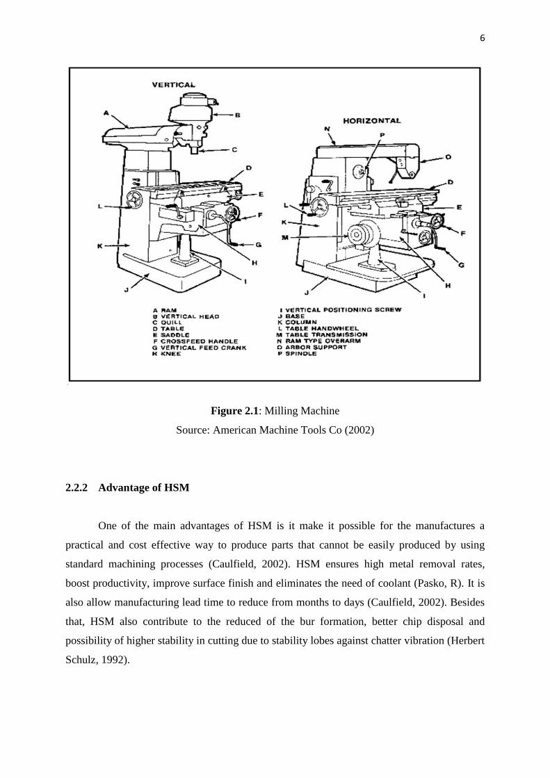
2.2.1 Background
Milling is the process of machining flat, curved, or irregular surfaces by feeding the
workpiece against a rotating cutter containing a number of cutting edges (J.W. Sutherland,
1999). The usual Mill consists basically of a motor driven spindle, which mounts and revolves
the milling cutter, and a reciprocating adjustable worktable, which mounts and feeds the
workpiece. Milling machines are often classed in two basic forms, horizontal and vertical,
which refer to the orientation of the main spindle. Both types range in size from small, bench-
mounted devices to room-sized machines. Unlike a drill press, this holds the workpiece
stationary as the drill moves axially to penetrate the material, milling machines also move the
workpiece radially against the rotating milling cutter, which cuts on its sides as well as its tip.
Workpiece and cutter movement are specifically controlled to less than 0.025 mm.
Milling machines also can be classified into several types such as that milling machine
that may be manually operated, mechanically automated, or digitally automated via computer
numerical control (CNC). Milling machines are able to perform several types of operations no
matter it is simple or complex such as keyway cutting, drilling or even contouring. Cutting
fluid is often pumped to the cutting area to cool and lubricate the cut.
Maximizing productivity is one of the most important objectives in the industry. As
for milling processes, there are certain criteria that contribute to maximizing the material
removal rate. The possible criteria were by increasing the spindle speed, increase the cutting
depth and increase the feed rate. The enhancements of milling machine technology have
contributed to the existence of machines with spindle speeds exceeding even 40,000 rpm.
6
Figure 2.1: Milling Machine
Source: American Machine Tools Co (2002)
2.2.2 Advantage of HSM
One of the main advantages of HSM is it make it possible for the manufactures a
practical and cost effective way to produce parts that cannot be easily produced by using
standard machining processes (Caulfield, 2002). HSM ensures high metal removal rates,
boost productivity, improve surface finish and eliminates the need of coolant (Pasko, R). It is
also allow manufacturing lead time to reduce from months to days (Caulfield, 2002). Besides
that, HSM also contribute to the reduced of the bur formation, better chip disposal and
possibility of higher stability in cutting due to stability lobes against chatter vibration (Herbert
Schulz, 1992).

7
2.3 CHATTER VIBRATION IN CUTTING
2.3.1 Background
Chatter can be defined as the vibrations that arise during the existence of relative
movements between cutting tool and the workpiece. It is belong to the class of self-excited
vibrations, which will definitely gives bad influence on surface finish, dimensional accuracy
of the workpiece, tool life or even machine life (Ivana Kovacic, 1998). Several studies have
been conducted on various mechanisms and characteristics of chatter. Cutting process with
feed that has varies is one of the principals of the arising chatter vibrations. As in figure 2.3
below, chatter produced when the tool tips have contact with the workpiece which producing
chips.
Figure 2.2: Cutting process with continuous chip formation
Source: Ivana Kovacic, 1998
2.4 VIBRATION ANALYSIS
Vibration can be most simply defined as a mechanical oscillatory motion. It is a
movement first in one direction and then back again in the opposite direction. For instance, by
a swinging pendulum, by the prongs of a tuning fork that has been struck, or by the string of a
musical instrument that has been plucked. Random vibrations are exhibited by the molecules

8
in matter. Any simple vibration is described by three factors which is its amplitude or size, its
frequency or rate of oscillation and the phase or timing of the oscillations relative to some
fixed time.
2.4.1 Types of Vibrations
1. Free vibration occurs when a mechanical system is set off with an initial input
and then allowed to vibrate freely. Examples of this type of vibration are
pulling a child back on a swing and then letting go or hitting a tuning fork and
letting it ring. The mechanical system will then vibrate at one or more of its
natural frequency and damp down to zero.
2. Forced vibration is when an alternating force or action is given to a mechanical
system. Examples of this type of vibration include transportation vibration
caused by its engine, its springs or road and also other external factors. Besides
that, the vibration of a building during an earthquake one of the forced
vibration example. In forced vibration, the frequency of the vibration is the
frequency of the force or motion applied, with order of magnitude being
dependent on the actual mechanical system.
2.4.2 Vibration Analysis Method
Vibration analysis method is a very useful method in order to perform the following
analysis:
Evaluating current machine condition
Diagnosing faults associated with operational machines
Monitoring and trending the overall condition of machines over time.
A complete vibration analysis would consist of three elements which is absolute
vibration measurements, bearing condition measurements and FFT frequency analysis. The
initial measurements, absolute vibration measurements, are an important indicator of the
current state of a machine. They can be measured quickly and easily and have been
successfully used for decades for the evaluation of overall machine condition (In-Plant
Services Inc)
9
2.5 STRUCTURE ANALYSIS
2.5.1 Modal Analysis
Modal analysis is defined as the study of the dynamic characteristics of a mechanical
structure. This application note emphasizes experimental modal techniques, specifically the
method known as frequency response function testing. Other areas are treated in a general
sense to introduce their elementary concepts and relationships to one another (Agilent
Technologies)
Although modal techniques are mathematical in nature, the discussion is inclined
toward practical application. Theory is presented as needed to enhance the logical
development of ideas (Agilent Technologies). Even though it’s quite complicated to explain
modal testing, in easy way it could be characterize in involving three basic steps and essential:
Exciting the dynamics of the structure
Measuring the excitation and structural response of this excitation
Analyzing the response to estimate modal characteristics of the future
Ideally, the excitation source should input a wide frequency range of energy to the
structure, usually in the form of a swept sine or impulse function. The excitation source is
normally an electrodynamics shaker or a modally tuned impact hammer. Modal responses are
usually measured as accelerations or displacements at various points on the structure. These
responses are commonly measured using optical, capacitive or eddy current displacement
transducers or piezoelectric accelerometers.
Data analysis requires data acquisition and signal processing of sufficient bandwidth.
Modal analysis can be performed using custom software programs or commercial analyzers
specifically designed for testing. These units typically perform Fast Fourier Transforms (FFT)
analyses and display system responses in the frequency domain.

10
2.5.1.1 Impact Hammer Modal Testing
The equipment required to conduct experimental impact hammer test includes a
modally tuned impact hammer, a vibration measurement device, and a two-channel analyzer
or data acquisition system. An impact hammer is a specialized piece of modal testing
equipment used to excite a structure by emulating an impulse forcing function. A force sensor
is attached to the tip of the hammer to provide the force measurement needed for analysis. A
pictorial representation of an impact hammer test is shown in figure.
Figure 2.3: Impact Hammer Modal Testing
Source: Manufacturing Automation Lab Inc (1999)
Theoretically, an impulse input provides infinite amplitude over infinitesimal time
duration, exciting all frequencies in the structure with constant amplitude. Basically, the
hammer will be in contact with the structure for a finite amount of time and will impart a
finite force. Considerable skill and technical resources are required to properly perform an
impact hammer test. The impact must be ‘clean’ to produce the required broadband excitation.
That is, it must be of very short duration and multiple knocks or bounces must be avoided.
Higher frequency excitation suffers as the pulse width or time of contact turn out to be longer.
Skill is also necessary to ensure consistent force input. Few machinists or production

11
engineers possess the experience or expertise to make impact hammer testing practical in the
machine shop environment (Caulfield, 2002).
2.5.1.2 Shaker Modal Testing
Even though the impact hammer is restricted to impulse force profiles, a number of
other inputs are suitable for modal testing. These forcing functions can be produced by a
signal generator or analyzer with appropriate output capability and amplified to power an
electromagnetic or electro hydraulic shaker. Excitation signals commonly used in modal
testing include:
Stepped or swept sinusoids
Random
Impulsive
Stepped and swept sine excitations are similar. A sinusoidal force is applied starting at
the lowest frequency of the range of interest and increased throughout the range. The stepped
sine excitation, as the name implies is applied in discrete steps with enough resolution to yield
meaningful Frequency Response Function (FRF) results. The swept sine excitation is
increased continually through the frequency range. The suitability of the sweep rate can be
tested by comparing measurements taken while sweeping up through the frequency range and
then again while sweeping down through the range. One drawback to using shakers on light
structures is the addition of mass, which may modify the modal characteristics. The frequency
response measured will not reflect the true system dynamics in this case. This could be a
significant limitation to the application of shaker testing on machine tools. Shaker tests
typically require more sophisticated and expensive equipment such as signal generators,
power amplifiers, and shakers rather than hammer impact tests (Caulfield, 2002).

12
Figure 2.4: Shaker Modal Testing
Source: Jacek F. Gieras (2005)
The proficiency required to conduct shaker tests is maybe less than that required for
impact hammer tests, but experience is required to set up the tests correctly. Tests can be
time-consuming to set up, might be as much as an hour or even more and that will makes this
method unfit for use in a production environment.
2.5.1.3 Non-contact Modal Testing
In the production environment, where chatter prediction is crucial, there is infrequently
an opportunity to properly set up and perform modal tests without creating significant
machine downtime. The impact of such tests on productivity is particularly severe for
procedures that must be performed every time a tool is changed. Both the shaker and impact
hammer approaches to modal testing are inconvenient to use on the shop floor. Not only do
they require time to properly set up and execute, they also require considerable skill and
experience to conduct. A more straightforward method is needed in order for chatter
prediction to be widely practiced (Caulfield, 2002)

13
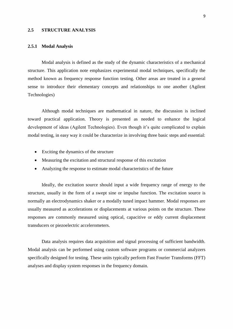
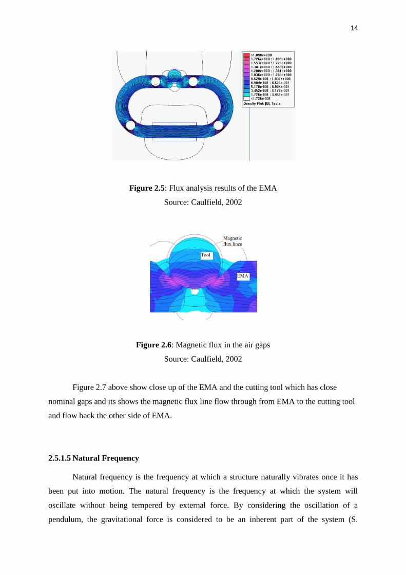
2.5.1.4 Electromagnet Actuator
Electromagnet actuator has been defined as the connecting links between information
processing systems components of a controlling system and a technical or non-technical
process (H. Janocha, 1992). From this observation towards this actuator working
characteristics, it shows that the actuators are the technical elements which can adjust and
control such as the flow of the energy. The imput might be just less power electrical signal but
the output shall be torque for motors or thrust for translational movements.
In order to generate mechanical energy by using electromagnet actuator, a force must
be produced by a magnetic field. The forces can be observed such as the current flow through
conductors which exposed to magnetic field like Lorenz force as an example. The other type
of forces also could be generated just simply by varying the reluctivity of the magnetic circuit
along with its path of movement which are called reluctance forces. In order to design this
actuator, both principles shall be applied on. Magnetic field for Lorenz force could be excited
by using a permanent magnet material or by using windings. Windings are a form of various
coils (E. Hering, 1999). However, normally both Lorenz and reluctance force effects are
superposed. Therefore it leads this study towards one really important step which is
determination of the change of the active air gap along the relative movement of the rotor and
stator geometry. It is really important since in this study it is crucial to calculate the accurate
force that will be produced later. However, the complicated geometries such as EMA model
in this study require advance numerical methods to determine the air gap forces accurately.
Figure 2.6 below show one of the EMA model design by Caulfield which possess nominal air
gaps and the air gap was calculated in order to solve numerical problems.
14
Figure 2.5: Flux analysis results of the EMA
Source: Caulfield, 2002
Figure 2.6: Magnetic flux in the air gaps
Source: Caulfield, 2002
Figure 2.7 above show close up of the EMA and the cutting tool which has close
nominal gaps and its shows the magnetic flux line flow through from EMA to the cutting tool
and flow back the other side of EMA.
2.5.1.5 Natural Frequency
Natural frequency is the frequency at which a structure naturally vibrates once it has
been put into motion. The natural frequency is the frequency at which the system will
oscillate without being tempered by external force. By considering the oscillation of a
pendulum, the gravitational force is considered to be an inherent part of the system (S.
Top Related