


Languages
Pages
Legal

Velcon Filters, LLC. • 1210 Garden of the Gods Road • Colorado Springs, CO 80907
Phone: 719-531-5855 • Fax: 719-531-5690 • E-mail: [email protected] www.velcon.com
Filter Vessel Manual (VF & HF Vessels)

1755
WARNING
DO NOT PRESSURE TEST THIS VESSEL WITH AIR!
PRESSURE TESTING
WITH AIR IS A HAZARDOUS PROCEDURE!
THIS VESSEL IS TO BE
PRESSURIZED ONLY WITH THE LIQUID FOR WHICH IT IS INTENDED TO BE USED,
AND ONLY TO THE MAXIMUM DESIGN PRESSURE OF THE
VESSEL.

Table of Contents General Description .......................................................................................... 2 Installation of Vessel ......................................................................................... 3 Start Up Procedure ............................................................................................ 4 Operating Information....................................................................................... 5 Cartridge Change or Inspection Procedure ....................................................... 7 Installation Instructions 09-868 (868) ............................................................... 8 Torque Requirements for Vessels (1935) ......................................................... 9 Installing Tie Rods (2013) .............................................................................. 10 Pleated Media Cartridges (1549) .................................................................... 12 Pleated Media Fo-6xxa3 Series (1888) ........................................................... 14 VF Series Fluid Filters (1221) ........................................................................ 16 Assembly Torque Recommendations (1801) ................................................. 18
DISCLAIMER: This generic vessel manual is provided on the web for your information, with the understanding that each vessel manual sent out from Velcon is customized for the particular vessel, and contains drawings and accessory information not included in this document. This document makes reference to other pieces of literature, such as schematics and drawings that are added to the manual as needed depending on the vessel parameters.

1507A-R2 11/11 PAGE 2
GENERAL DESCRIPTION The Velcon Filter that you have received consists of the vessel, filter elements, and accessory equipment to meet your specific requirements. Descriptive literature covering the accessories is included near the back of this manual. A Velcon Filter is specifically designed to remove solid contaminants from the product being filtered. The product enters from the inlet nozzle, rising vertically behind a baffle until it reaches the region above the top of the highest elements. The elements are arranged in vertical stacks rising up from a flat division plate. The fluid enters the outside of each element and flows toward the center of the element. The flow then goes downward to the outlet. Velcon Filters are manufactured to meet a variety of different end uses and specifications. The finest workmanship has gone into the building of this Velcon Filter. It is of no value, however, if elements are improperly installed or the unit is improperly operated. We urge you to read the manual carefully and follow the instructions given.
Velcon has qualified the FO-6xxA3 pleated media filter cartridges to EI Specification 1590, “Specifications and Qualification Procedures
for Aviation Fuel Microfilters.”

1507A-R2 11/11 PAGE 3
INSTALLATION OF VESSEL 1. Identify the Filter inlet and outlet by the markings provided on the vessel
piping. The Filter must be installed in the correct direction of flow to perform properly and to avoid damage to the system.
2. INLET and OUTLET PIPING should be carefully aligned to avoid stressing the Filter connections during installation. Installation of shut-off valves on either side of the Filter is recommended so that it can be independently drained for cartridge change or inspection.
CAUTION: STEPS 3 AND 4 SHOULD BE PERFORMED BEFORE REMOVING HINGE OR PIVOT MOUNTED COVER TO INSURE STABILITY OF THE FILTER.
3. Bolt the Filter to a stable base.
4. Carefully install correct gaskets on the inlet and outlet connections and connect to the inlet and outlet piping.
5. Connect any accessories that are not already installed. See Accessory Parts List and literature as required.
6. Cartridges are normally packed separately. Open the vessel cover and install cartridges as explained on page 8 and as per enclosed element stack drawing. Tighten nuts on tie rods until the rubber washers begin to curl. Do not over-torque.
7. Be sure the cover gasket is in place and properly aligned. Replace cover and secure tightly.
8. NOTE: FILTERS MUST BE PROVIDED WITH PRESSURE RELIEF VALVES IF THE SYSTEM HAS POSITIVE DISPLACEMENT PUMPS UPSTREAM OR AUTOMATIC SHUT-OFF VALVES DOWNSTREAM OF THE VESSEL.
1507A-R2 11/11 PAGE 4
START UP PROCEDURE
If the Velcon Filter has the accessories listed below, they should be placed in the following positions:
1. Manual drain valves closed.
2. Manual air eliminator valve open.
3. The valves in the inlet and outlet piping should be closed.
4. The pressure gauge valve to OFF position. For Filters equipped with selector valves, this is done by turning the handle outward so that the arrow points toward the vessel.
For information on operation of accessories, turn to Accessory Instructions in the back of the manual.
After the valves have been positioned as outlined, the unit is ready to be filled.
The following operating instructions can be used for initial start-up and for subsequent start-ups after installation of replacement elements or servicing of the unit.
1. Start the system pump.
2. Slightly open the inlet valve, allowing the Filter to slowly fill with fluid. (Take about 10 – 15 minutes to fill the vessel to eliminate the possibility of an internal fire.)
3. If the unit is equipped with a manual air eliminator valve, leave the valve cracked open until the fluid flows from the opening; then close quickly.
4. If equipped with an automatic air eliminator, the unit is filled when the air eliminator stops flowing air. When the Velcon Filter is filled with fluid, slowly open the valve on the inlet line, then slowly open the valve on the outlet line.
5. When the unit is in operation, open the pressure gauge, take a differential pressure reading and record the reading. If there is no pressure differential, the system should be shut down and the Filter inspected for broken seals or possibly elements left out. See Differential Pressure Readings on Page 5.
1507A-R2 11/11 PAGE 5
OPERATING INFORMATION
Below are the Velcon recommendations for operating procedures. Your Company Maintenance and/or Quality Control procedures may provide alternate instructions on these matters.
1. FILTER CARTRIDGES should be changed in accordance with one of the following (whichever comes first):
A. When the differential pressure reaches the level specified on the cover page of this manual. For Filters equipped with differential pressure gauges, see paragraph 2 below.
B. When the flow rate is reduced to an unacceptable level because the cartridges are plugged with contaminant.
C. Whenever effluent product is unacceptably contaminated.
2. DIFFERENTIAL PRESSURE READINGS Differential pressure is the difference between the pressure upstream and downstream of the Filter. Differential pressure increases when contaminant is filtered by the filter cartridges and causes flow restriction. Readings should be taken when the system is flowing at maximum capacity. If the Filter is equipped with a direct reading differential pressure gauge, the reading shown on the gauge is the differential pressure across the Filter. If the Filter is equipped with a pressure gauge and a selector valve, use the following procedure for determining differential pressure:
A. Turn the handle one way and record the pressure reading.
B. Turn the handle the other way (90° or 180°, depending on the type of valve) and record the pressure reading.
C. Subtract the lower reading from the higher reading to determine differential pressure. (The higher reading is inlet pressure.)

1507A-R2 11/11 PAGE 6
Differential pressure readings should be taken at least once during every operating week and more frequently in high throughput installations or when the differential is increasing rapidly. Records of the differential pressure and throughput should be maintained to determine when cartridges should be changed.
A sudden drop in pressure differential is an indication of a possible problem. Check first to be sure that readings were taken at equivalent flow rates. If so, shut the system down, open the Filter, and inspect for the following:
a. Collapsed or ruptured cartridges caused by severe pressure differential or shocks in excess of design limits.
b. Ruptured seals. Check to see that all O-ring seals and gaskets seals are in place and have the same alignment as when the elements and parts were installed.
c. Broken end plates. Inspect all of the end plates of the elements.
d. If any of the above are observed, check the system for possible hydraulic shock conditions. If the system is not provided with adequate surge controls, the sudden start-up of a high-pressure pump can create extremely high shock loads that may exceed the design of these components.

1507A-R2 11/11 PAGE 7
CARTRIDGE CHANGE OR INSPECTION PROCEDURE
A. Shut off the pump.
B. Close the inlet and outlet pipe valves.
C. Open the drain valves and remove the product from the Filter.
D. Open the manual air eliminator valve. This will permit the unit to drain faster.
E. Open the cover and inspect the cover gasket – replace the gasket if it is damaged.
F. Completely drain filter chamber.
G. Remove spent cartridges for cartridge change.
H. Wipe off or wash down any foreign matter from the vessel interior.
I. Install the cartridges in accordance with instructions on page 8.
J. Tighten nuts on tie rods until the rubber washers begin to curl. Do not over-torque.
K. Check the cover gasket for alignment, replace the cover and secure tightly. The Filter is now ready for the start-up procedure.
USE ONLY VELCON FILTERS LLC. CARTRIDGES IN THIS FILTER. VELCON CANNOT WARRANT PERFORMANCE IF ANY OTHER MANUFACTURER’S CARTRIDGES ARE USED.
To reorder cartridges and replacement parts or to obtain further information contact your Velcon Filters, LLC representative
Or VELCON FILTERS, LLC.
1210 Garden of the Gods Road Colorado Springs, CO 80907-3410
Phone: 719-531-5855 Fax: 719-531-5690
E-mail: [email protected] Web site: www.velcon.com

868-R11 09/11P/N 09-868
©2011 Velcon Filters, LLC Due to Velcon Filters, LLC continuing product improvement, drawings, specifications, and pictures are subject to change without notice.
For information on recycling used filters, contact FILCare, 719-499-1379
INSTALLATION Instructions1210 Garden of the Gods Rd.
Colorado Springs, CO 80907Phone: (719) 531-5855 FAX: (719) 531-5690
email: [email protected] /web site: www.velcon.com
1. Turn off pump. Close inlet and outlet valves and open drain valve. Open the air eliminator or manual bleed valve and drain the vessel.
2. Open vessel after making sure the vessel is completely drained.
3. Jack-up head and swing aside. Remove the spider (if installed). Remove nuts and washers, endcaps, old car-tridges, and center plates, if any.
4. Wipevesselcleanwheneverpossibleorflush.5. The cartridges are packaged in individual poly-bags (the
anti-static poly-bag protects the cartridge from being dis-armed by handling, and prevents build up of static charge to cartridge). Cut the bag at the one end and slide it back a few inches. DO NOT TOUCH THE OUTER FILTER MEDIA.
6. Place cartridge over the center rod making sure the car-tridge is centered over the guide bar or mounting adapter attached to the deck plate. The cartridge must be seated flatagainsttheadapterordeckplate.Removethepoly-bag SLOWLY from the cartridge after it is in place.
7. Forvesselswithstackedcartridges,placethefirsttieroffiltercartridgesinpositionatallbulkheadports(perstep6). Insert center plate onto center rod and insert into each cartridge. Next, install the second tier of cartridges over the center plates. There must always be a center plate between every two stacked cartridges. Be sure the circular guide on both sides of the center plate projects into each cartridge.
8. When all cartridges are loaded, insert sealing cap over center rod.
9. Installrubberwasher,flatwasher,lockwasher,andnutin that order, onto each center rod. Tighten to 4 to 5 foot poundsoftorque.(DONOTtouchtheouterfiltermedia.)
10. Make sure that no poly-bags remain in the housing. (If spider is not included proceed to step #11) Replace the spider as follows:• Installtheflatwasherovereachcartridgeendand
install the spider over the ends of the cartridges.• Affixthespidertothethreadedclipsonthevessel
walls using the nut and lockwasher.
OPEN-ENDED FILTER CARTRIDGES • Adjustthespiderclipnuts,sothespiderliesflatonthe
ends of the cartridges• Install the washer and nut over the ends of the car-tridges,toaffixthespidertothecartridgeends.Snugthe nuts. DO NOT TIGHTEN YET.
• Adjust the ends of each cartridge to create even separation between the cartridges and between the cartridge and vessel wall. Cartridges should NOT be touching each other, nor touching the vessel wall. The ends of the cartridges can be shifted within the spider plate holes as follows:
Cartridge Length
Shift Within the Spider Hole
Greater than 33" Full movement within the spider hole
30" Less than 5/8" (16 mm)28" Less than 9/16" (14 mm)24" Less than 1/2" (12 mm)22" Less than 1/2" (12 mm)20" Less than 3/8" (10 mm)18" Less than 3/8" (10 mm)16" Less than 1/4" (8 mm)14" Less than 1/4" (6 mm)11" Less than 1/4" (5 mm)9" Less than 3/16" (5 mm)
• When the cartridges are spaced properly, tighten the spider nuts to 5 ft-lbs.
11. Inspect the cover gasket and replace it if necessary. Tighten the cover securely in a cross-pattern process.
12. Close the drain valve and start the system pump.13. With the outlet valve closed, slightly open the inlet valve
andallowthevesseltofillSLOWLY with fuel until the air eliminatorclosesorfluidbeginstoflowfromthemanualair vent. Close the vent valve. Fully open the inlet valve.
14. Open the outlet valve SLOWLY.15. When the unit is operating, check the differential pres-
sure across the cartridges. There should be indication of positive pressure, normally 1-5 psid. This insures that all seals have been properly made during the installation.
OPERATING PROCEDURES Velcon Recommended Cartridge Changeout (Also refer to your company guidelines)
FilterCartridges:3yearsor25psid,whicheveroccursfirst.(INSPECT VESSEL ANNUALLY)

1935-R1 09/112011 Velcon Filters, LLC
Bolted pressure vessel closures operate on the premise that the joint is clamped closed with a force sufficient to resist the internal pressure yet still maintain a seal. The clamping force, or pre-load, is applied by the closure bolts and its magnitude is controlled by the torque applied. Application of the correct preload is essential to maintaining a positive seal and avoiding closure failures from fatigue or overstressed vessel components.
The short term, and most obvious effect of grossly under-torqued bolts is insufficient clamping force resulting in a leaking closure. A more ominous result of under-torqued bolts in systems which see a great number of pressure cycles (such as refuelers, loading racks etc.), is bolt fatigue failure. Repeated applications of stress to the bolt eventually create a small crack at the surface of the bolt which continues to grow until the bolt breaks and the closure fails.
It is a good idea to re-torque the closure bolts after they have been in use for a month or so to ensure the joint has not “relaxed” and the preload reduced.
Over-torquing closure bolts will result in breaking or bending vessel bolt clips or actually breaking the bolt itself. Table One lists guideline torque
values for lubricated bolts for common sizes used for vessel closures. Always use lubricated bolts, as this reduces the required torque, improves torque accuracy, and retards corrosion.
A common cause of inaccurate bolt torque is inappropriate bolt torquing procedures. Key elements to the procedure are application of the torque in stages and in a specific cross-torquing sequence. For most applications, torque is applied to all bolts to 30% of full torque, then to all bolts to 60% of full torque, and finally to all bolts to 100% of full torque. Each torquing cycle is carried out in the applicable cross-torquing sequence. Torquing sequences vary with the number of bolts on the cover.
The tightening pattern is as follows: Tighten two bolts diametrically opposite from each other, then tighten a second pair of bolts
diametrically opposite each other, approximately 90 degrees away from the first pair, and so on until all bolts have been tightened.
Using a clock as an example, the sequence would be: 12, 6, 9, 3, 11, 5, 10, 4, 7, 1, 8, 2.
On large vessels, the cross-torquing process is tedious but the addition of a second operator applying torque improves the situation vastly.
Correct closure torquing will result in many years of trouble-free vessel operation. Occasional inspections for bolt cracks or clip damage is good practice to detect possible closure problems before they occur. More detailed or specific information on bolt torquing requirements and procedures can be obtained by calling Jim Head at (719) 528-7255.
1210 Garden of the Gods Rd, Colorado Springs, CO 80907
Phone: (719) 531-5855 FAX: (719) 531-5690
E-mail: [email protected] / web site: www.velcon.com
INSTALLATION Instructions
TORQUE REQUIREMENTS FOR VESSELS WITH “O-RING CLOSURE”
*NOTE: These recommended torque values are only for vessels with an O-Ring closure.
TABLE ONE*Bolt Diameter (inches) Recommended Torque (ft-lb)
1/2” 203/4” 451” 100
1-1/4” 1601-1/2” 260
2013 01/08©2008 Velcon Filters, Inc.
INSTALLATIONInstructions
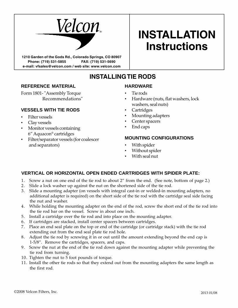
INSTALLING TIE RODS
1210 Garden of the Gods Rd., Colorado Springs, CO 80907Phone: (719) 531-5855 FAX: (719) 531-5690
e-mail: [email protected] / web site: www.velcon.com
VERTICAL OR HORIZONTAL OPEN ENDED CARTRIDGES WITH SPIDER PLATE:1. Screw a nut on one end of the tie rod to about 2” from the end. (See note, bottom of page 2.)2. Slide a lock washer up against the nut on the shortened side of the tie rod.3. Slide a mounting adapter (on vessels with integral cast-in or welded-in mounting adapters, no
additional adapter is required) on the short side of the tie rod with the cartridge seal side facingthe nut and washer.
4. While holding the mounting adapter on the end of the rod, screw the short end of the tie rod intothe tie rod bar on the vessel. Screw in about one inch.
5. Install a cartridge over the tie rod and into place on the mounting adapter.6. If cartridges are stacked, install center spacers between cartridges.7. Place an end seal plate on the top or end of the cartridge (or cartridge stack) with the tie rod
extending out from the end seal plate tie rod hole.8. Adjust the tie rod by screwing it in or out until the amount extending beyond the end cap is
1-5/8”. Remove the cartridges, spacers, and caps.9. Screw the nut at the end of the tie rod down against the mounting adapter while preventing the
tie rod from turning.10. Tighten the nut to 5 foot pounds of torque.11. Install the other tie rods so that they extend out from the mounting adapters the same length as
the first rod.
HARDWARE• Tie rods• Hardware (nuts, flat washers, lock
washers, seal nuts)• Cartridges• Mounting adapters• Center spacers• End caps
MOUNTING CONFIGURATIONS• With spider• Without spider• With seal nut
REFERENCE MATERIALForm 1801- "Assembly Torque
Recommendations"
VESSELS WITH TIE RODS• Filter vessels• Clay vessels• Monitor vessels containing
6” Aquacon® cartridges• Filter/separator vessels (for coalescer
and separators)

-2-
VERTICAL OR HORIZONTAL OPEN ENDED CARTRIDGES WITH NO SPIDER PLATE:1. Screw a nut on one end of the tie rod to about 2” from the end. (See note below.)2. Slide a lock washer up against the nut on the shortened side of the tie rod.3. Slide a mounting adapter (on vessels with integral cast-in or welded-in mounting adapters, no
additional adapter is required) on the short side of the tie rod with the cartridge seal side facingthe nut and washer.
4. While holding the mounting adapter on the end of the rod, screw the short end of the tie rodinto the tie rod bar on the vessel. Screw in about one inch.
5. Install a cartridge over the tie rod and into place on the mounting adapter.6. If cartridges are stacked, install center spacers between cartridges.7. Place an end seal plate on the top or end of the cartridge (or cartridge stack) with the tie rod
extending out from the end seal plate tie rod hole.8. Adjust the tie rod by screwing it in or out until the amount extending beyond the end seal plate
is one (1) inch.9. Remove the cartridges, spacers, and seal plates.10. Screw the nut at the end of the tie rod down against the mounting adapter while preventing the
tie rod from turning.11. Tighten the nut to 5 foot pounds of torque.12. Install the other tie rods so that they extend out from the mounting adapters the same length as
the first rod.
SEPARATOR WITH SEAL NUT (WITH OR WITHOUT SPIDER PLATE):1. Screw a nut on one end of the tie rod to about 2” from the end. (See note below.)2. Slide a lock washer up against the nut on the shortened side of the tie rod.3. Slide a mounting adapter (on vessels with integral cast-in or welded-in mounting adapters, no
additional adapter is required) on the short side of the tie rod with the cartridge seal side facingthe nut and washer.
4. While holding the mounting adapter on the end of the rod, screw the short end of the tie rodinto the tie rod bar on the vessel. Screw in about one inch.
5. Install a separator over the tie rod and into place on the mounting adapter so the tie rod extendsfrom the end seal cap tie rod hole.
6. On double open ended separators, place an end seal plate on the top or end of the separator,with the tie rod extending out from the end seal plate tie rod hole.
7. Adjust the tie rod by screwing it in or out until the amount extending beyond the end seal plateis one (1) inch.
8. Remove the cartridges, spacers, and seal plates.9. Screw the nut at the end of the tie rod down against the mounting adapter while preventing the
tie rod from turning.10. Tighten the nut to 5 foot pounds of torque.11. Install the other tie rods so that they extend out from the mounting adapters the same length as
the first rod.
NOTE:1. In AHM06xxx, AVM06xxx, HM06xxx, and VM06xxx Aquacon® vessels, the nut
should be screwed on to the tie rod to about 4" from the end instead of 2".2. In three stage HVM-xxxx filter/separator vessels, the nut on the separator tie rods
should be screwed on to the tie rod to about 4” from the end instead of 2”.

© 2011 Velcon Filters, LLC 1549-R12 01/11
Pleated Media Filter Cartridges
High Efficiency, Long Life Cartridges for Industrial Fluids
FO-412PLxx FO-718PLxx FO-614PLFxx FO-512PLxx
• Large Surface Area – Allows high flow rate with low initial pressure drop and maximum contaminant holding capacity.
• Resin Impregnated Media – Maintains strength, resists effects of water and heat.• 75 psi Collapse Strength – Heavy gauge carbon steel endcaps and center tube give safety margin
against pressure surges.• Coated Steel Components – Resist corrosion from most industrial fluids.• Corrugated Media – Prevents pleat pinch-off, assuring all filtration media is utilized.• Buna-N Gaskets – The best general gasket material available assures positive seal in most fluids.• Thermoset Bonding Material – Durable endcap-to-media bond prevents internal bypassing.• Threaded base filter cartridges – Available for easier installation.
APPLICATIONSVelcon Pleated Media Cartridges are suitable for a broad range of polar and non-polar fluids. Recommended for applications where the contaminant is granular (non-colloidal), allowing maximum utilization of the high surface area.
Suitable for:All Hydrocarbon Fuels Cutting Oils Insulating Oils Glycols Toluol NaphthaDiesel Fuel Lube Oils Hydraulic Oils Water Emulsion CoolantsBiodiesel Fuel Synthetic Oils Ethyl Alcohol Degreasing Fluids
Photos - please note: The outer wrap of a cartridge can be either nylon jacket, beaming paper, or PVC-coated screen wrap. Actual cartridges may not look exactly like those shown in photo. In the part numbers above, “xx” represents micron rating of the cartridge.
FO-644PLFxxTB
75 psi Collapse strength5 - 9 Operating pH rangeMicron ratings from 1/4 to 7598%+ Nominal filtration efficiency
250°F Maximum operating temperatureRecommended changeout differential pressure - 25 psidMulti-pass (Beta Ratio) data available on request
SPECIFICATIONS
For information about Flow Ratings with various viscosity fluids, refer to Form #1532

COMPANY HEADQUARTERS:Velcon Filters, LLC1210 Garden of the Gods RoadColorado Springs, CO 80907-3410Phone: 1.800.531.0180 / 1.719.531.5855Fax: 719.531.5690e-mail: [email protected]
MANUFACTURING PLANTS LOCATED AT:Colorado Springs, ColoradoSylacauga, AlabamaHenryetta, Oklahoma
OFFICES AND AFFILIATES IN:Canada, Germany, Singapore, & Spain
Liquid Filtrationand Separation
SpecialistsDue to Velcon Filters’ continuing product improvement, drawings, specifications and pictures are subject to change without notice.
Velcon products are sold and serviced by a world-wide representativenetwork. To order, contact Headquarters or your LOCAL REPRESENTATIVE:
CARTRIDGE INFORMATIONThe following table lists a few of the broad range of available Velcon cartridges. Your local Velcon Representative can provide more complete information.
Dimensions ModelNominal Micron Rating
Protective Outer Wrap
4” x 12¼”x 1¾” ID
FO-412PL2 2 No
FO-412PL5 5 No
4” x 18”x 1¾” ID
FO-418PL5 5 No
FO-418PL15 15 No
For VF-61 & VF-61E Housing
FO-512PL1/2 ½ No
FO-512PL05 5 No
FO-512PL25 25 No
For VF-62 Housing
FO-524PL1/2 ½ No
FO-524PL05 5 No
FO-524PL25 25 No
6” x 14½”x 3½” ID
FO-614PLF½ ½ No
FO-614PLF1 1 No
FO-614PLF2 2 No
FO-614PLF5 5 No
FO-614PLF5M 5 Yes
FO-614PLF10 10 No
FO-614PLF15 15 No
FO-614PLF15M 15 Yes
FO-614PLF25 25 No
FO-614PLF25M 25 Yes
FO-614PLF75 75 No
6” x 29”x 3½” ID
FO-629PLF1/4 ¼ Yes
FO-629PLF1/2 ½ Yes
FO-629PLF1 1 Yes
FO-629PLF2 2 Yes
FO-629PLF5 5 Yes
FO-629PLF10 10 Yes
FO-629PLF20 20 Yes
FO-629PLF25 25 Yes
6” x 29” Threaded
Base
FO-629PLF1/2TB ½ Yes
FO-629PLF1TB 1 Yes
FO-629PLF2TB 2 Yes
FO-629PLF5TB 5 Yes
FO-629PLF25TB 25 Yes
Dimensions ModelNominal Micron Rating
Protective Outer Wrap
6” x 44”x 3½” ID
FO-644PLF1/2 ½ No
FO-644PLF1M 1 Yes
FO-644PLF2M 2 Yes
FO-644PLF5M 5 Yes
FO-644PLF10M 10 Yes
FO-644PLF15M 15 Yes
FO-644PLF25M 25 Yes
6” x 44” Threaded Base
FO-644PLF1/4TB ¼ Yes
FO-644PLF1/2TB ½ Yes
FO-644PLF1TB 1 Yes
FO-644PLF2TB 2 Yes
FO-644PLF5TB 5 Yes
FO-644PLF10TB 10 Yes
FO-644PLF25TB 25 Yes
6” x 56” x 3½” ID
FO-656PLF1M 1 Yes
6” x 56” Threaded Base
FO-656PLF1/2TB ½ Yes
FO-656PLF1TB 1 Yes
FO-656PLF2TB 2 Yes
FO-656PLF5TB 5 Yes
FO-656PLF25TB 25 Yes
6¼” x 18”x 29/16” ID
FO-718PLP3 0.3 No
FO-718PL1/2 ½ No
FO-718PL01 1 Yes
FO-718PL02 2 Yes
FO-718PL05 5 Yes
FO-718PL10 10 Yes
FO-718PL15 15 Yes
FO-718PL25 25 Yes
FO-718PL50 50 Yes
6¼” x 36”x 29/16” ID
FO-736PLP3 0.3 No
FO-736PL1/2 ½ No
FO-736PL05 5 Yes
FO-736PL15 15 Yes
8” x 221/8”x 2” ID
FO-822PLP3 0.3 No
FO-822PL1/2 ½ No
FO-822PL05 5 No
8” x 29½”x 2” ID
FO-829PL05 5 No
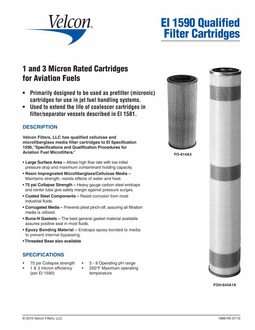
DESCRIPTION
Velcon Filters, LLC has qualified cellulose and microfiberglass media filter cartridges to EI Specification 1590, “Specifications and Qualification Procedures for Aviation Fuel Microfilters.”
• Large Surface Area – Allows high flow rate with low initial pressure drop and maximum contaminant holding capacity.
• Resin Impregnated Microfiberglass/Cellulose Media – Maintains strength, resists effects of water and heat.
• 75 psi Collapse Strength – Heavy gauge carbon steel endcaps and center tube give safety margin against pressure surges.
• Coated Steel Components – Resist corrosion from most industrial fluids.
• Corrugated Media – Prevents pleat pinch-off, assuring all filtration media is utilized.
• Buna-N Gaskets – The best general gasket material available assures positive seal in most fluids.
• Epoxy Bonding Material – Endcaps epoxy-bonded to media to prevent internal bypassing.
• Threaded Base also available
EI 1590 Qualified Filter Cartridges
© 2010 Velcon Filters, LLC. 1888-R5 07/10
FOH-644A1K
1 and 3 Micron Rated Cartridgesfor Aviation Fuels
• Primarilydesignedtobeusedasprefilter(micronic)cartridgesforuseinjetfuelhandlingsystems.
• Usedtoextendthelifeofcoalescercartridgesinfilter/separatorvesselsdescribedinEI1581.
FO-614A3
• 5 - 9 Operating pH range• 250°F Maximum operating
temperature
• 75 psi Collapse strength• 1 & 3 micron efficiency
(per EI 1590)
SPECIFICATIONS

COMPANY HEADQUARTERS:Velcon Filters, LLC1210 Garden of the Gods RoadColorado Springs, CO 80907-3410Phone: 1.800.531.0180 / 1.719.531.5855Fax: 719.531.5690e-mail: [email protected]
MANUFACTURING PLANTS LOCATED AT:Colorado Springs, ColoradoSylacauga, AlabamaHenryetta, Oklahoma
OFFICES & AFFILIATES IN:Canada, Germany, Singapore & Spain
Liquid Filtrationand Separation
SpecialistsDue to Velcon Filters’ continuing product improvement, drawings, specifications and pictures are subject to change without notice.
Velcon products are sold and serviced by a world-wide representativenetwork. To order, contact Headquarters or your LOCALREPRESENTATIVE:
VELCON MODEL NUMBER
DIMENSIONSOUTER WRAP
API MICRONEFFICIENCY
MAXIMUM FLOW RATE
FO-614A3 6” x 141/2” x 31/2” ID NO 3 53
FO-614A3TB 6” x 141/2” x 31/2” ID NO 3 47
FO-629A3 6” x 29” x 31/2” ID YES 3 111
FO-629A3TB 6” x 29” x 31/2” ID YES 3 105
FO-644A3 6” x 44” x 31/2” ID YES 3 171
FO-644A3TB 6” x 44” x 31/2” ID YES 3 165
FO-656A3 6” x 56” x 31/2” ID YES 3 219
FO-656A3TB 6” x 56” x 31/2” ID YES 3 213
FOH-614A1K 6” x 141/2” x 31/2” ID YES 1 53
FOH-614A1KTB 6” x 141/2” x 31/2” ID YES 1 47
FOH-629A1K 6” x 29” x 31/2” ID YES 1 111
FOH-629A1KTB 6” x 29” x 31/2” ID YES 1 105
FOH-644A1K 6” x 44” x 31/2” ID YES 1 171
FOH-644A1KTB 6” x 44” x 31/2” ID YES 1 165
FOH-656A1K 6” x 56” x 31/2” ID YES 1 219
FOH-656A1KTB 6” x 56” x 31/2” ID YES 1 213
Please see Data Sheet #1936 for more information about the FOH Series Cartridges.
CARTRIDGE INFORMATION

STANDARD DESIGN FEATURES
• 150 psi welded steel ASME Code construction.
• Choice of micron rating from 0.5 to 75 microns.
• Choice of pleated or depth type media.
• Epoxy coated interior, primed exterior.
• Buna-N O-ring cover seals.
RECOMMENDED OPTIONAL ACCESSORIES
• Automatic Air Eliminator
• Pressure Relief Valve
• Differential Pressure Gauge
• Drain Valve(s)
• Sampling Probes
• ASME Code Stamp
TYPICAL APPLICATIONS
Consult our cartridge data sheets to select the micron rating and type of cartridge that is right for your application – PLF Series (pleated surface type filtration), FG Series (fiberglass depth type filtration), or Aquacon® Series (dehydration and filtration).
VF1614 and larger vessels, such as the VF2044150 shown at top right, are provided with swing bolt closure, RF flange connections and fittings for pressure gauge, air eliminator, pressure relief valve and drain valve.
© 2010 Velcon Filters, LLC. 1221-R21 03/10
Vertical Filter VesselsVF Series
VF814150
VF2044150
Filter vessels VF814 through VF844, such as the VF814150 shown at right, have through-bolt covers, NPT connections, and include fittings for drain, pressure gauge and air vent.
Note: In applications where increased dirt contamination is present, it may be desirable to oversize filtration equipment. Contact Velcon for oversizing recommendations. For API/EI applications, please consult Velcon
GasolineDiesel FuelsJet Fuels

COMPANY HEADQUARTERS:Velcon Filters, LLC1210 Garden of the Gods RoadColorado Springs, CO 80907-3410Phone: 1.800.531.0180 / 1.719.531.5855Fax: 719.531.5690e-mail: [email protected]
MANUFACTURING PLANTS LOCATED AT:Colorado Springs, ColoradoSylacauga, AlabamaHenryetta, Oklahoma
OFFICES AND AFFILIATES IN:Canada, Germany, Singapore, & Spain
Liquid Filtrationand Separation
SpecialistsDue to Velcon Filters’ continuing product improvement, drawings, specifications and pictures are subject to change without notice.
Velcon products are sold and serviced by a world-wide representativenetwork. To order, contact Headquarters or your LOCAL REPRESENTATIVE:
Flow rates are for FO-614PLF series pleated paper cartridges. For higher viscosity fluids, consult your Velcon Representative.
VF Series Filters are designed to accommodate our standard 6 in. O.D., 31/2 in. I.D., 141/2 in. long cartridges that are stacked one, two, or three high. Many cartridges are available in longer lengths that eliminate stacking. For example, a 44 inch long FO-644PLF1M could be used in place of three 141/2 inch long cartridges. This makes for easier and less expensive changeouts.
A number of threaded base filter cartridges (e.g. FO-644PLF5TB) are available, which allow for easier cartridge changeout and removal of particulate matter from the deckplates. See data sheet #1549. The threaded base cartridges mount on the 6000T Adapters.
Dimensions shown are for estimating purposes only. For exact dimensions, obtain certified drawing.
VF16 and VF20 Series vessels have flat covers. VF16 Series vessels do not have hydraulic lift jacks.
Available Aquacon® Cartridges are AC-6xx05 and AD-6xx25 where xx represents cartridge lengths of 14, 29, and 44 inches.
1.
2.
3.
4.
5.
6.
Vessel Model
Number
Maximum FlowUSGPM
FO Series Cartridges Fig.
No.
Dimensions in InchesWeight
with Skid, lbs.
VolumeU.S.
GallonsLength Qty.Jet Fuel Gasoline Diesel A B C D E F G H I J K
VF814 67 68 65 14 1 2 85/8 3 243/4 263/4 39 2 13 103/8 61/2 - - 225 5
VF829 133 136 130 29 1 2 85/8 3 39 411/8 68 2 13 103/8 61/2 - - 265 8
VF844 200 204 195 44 1 2 85/8 3 571/16 597/16 101 2 13 103/8 61/2 - - 305 11
VF1614 267 272 260 14 4 1 16 15 3713/16 4013/16 52 4 241/4 9 75/8 75/8 187/16 500 22
VF1629 533 544 520 29 4 1 16 15 5213/16 5513/16 82 4 241/4 9 75/8 75/8 187/16 560 35
VF1644 800 816 780 44 4 1 16 15 663/4 693/4 110 4 241/4 9 75/8 75/8 187/16 620 48
VF2029 800 816 780 29 6 1 20 191/2 601/8 655/8 89 6 28 13 71/2 71/2 26 1000 67
VF2044 1200 1224 1170 44 6 1 20 191/2 745/8 807/16 118 6 28 13 71/2 71/2 26 1100 88
VF2829 1600 1632 1560 29 12 1 28 24 481/2 641/4 77 8 36 18 9 9 35 1500 125
VF2844 2400 2448 2340 44 12 1 28 24 643/8 793/4 108 8 36 18 9 9 35 1600 165
VF3644 3600 3672 3510 44 18 1 365/8 26 633/8 84 109 10 48 23 121/2 121/2 44 2250 288
VF4244 5400 5508 5265 44 27 1 423/4 28 66 873/8 110 12 54 28 13 13 521/4 3800 400
Figure 1 Figure 2
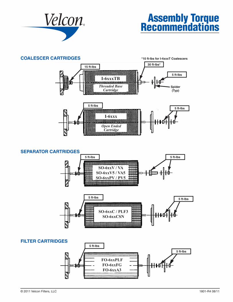
© 2011 Velcon Filters, LLC 1801-R4 08/11
Assembly Torque Recommendations
SEPARATOR CARTRIDGES
COALESCER CARTRIDGES
FILTER CARTRIDGES
*10 ft-lbs for I-4xxxT Coalescers
15 ft-lbs
5 ft-lbs
5 ft-lbs
5 ft-lbs
5 ft-lbs
5 ft-lbs
5 ft-lbs
5 ft-lbs
5 ft-lbs
30 ft-lbs*
Spider(Typ)
I-6xxxTB
I-6xxx
Threaded Base Cartridge
Open Ended Cartridge
SO-6xxV / VASO-6xxV5 / VA5SO-6xxPV / PV5
SO-6xxC / PLF3SO-6xxCSN
FO-6xxPLFFO-6xxFGFO-6xxA3
5 ft-lbs

COMPANY HEADQUARTERS:Velcon Filters, LLC1210 Garden of the Gods RoadColorado Springs, CO 80907-3410Phone: 1.800.531.0180 / 1.719.531.5855Fax: 719.531.5690e-mail: [email protected]
MANUFACTURING PLANTS LOCATED AT:Colorado Springs, ColoradoSylacauga, AlabamaHenryetta, Oklahoma
OFFICES AND AFFILIATES IN:Canada, Germany, Singapore, & Spain
Liquid Filtrationand Separation
SpecialistsDue to Velcon Filters’ continuing product improvement, drawings, specifications and pictures are subject to change without notice.
Velcon products are sold and serviced by a world-wide representativenetwork. To order, contact Headquarters or your LOCAL REPRESENTATIVE:
Aquacon® CARTRIDGES
TORQUE CONVERSION TABLE
ft-lbs inch-lbs kg-m N-m
5 60 0.69 6.78
10 120 1.38 13.56
15 180 2.07 20.34
20 240 2.77 27.12
30 360 4.15 40.67
5 ft-lbs
5 ft-lbs
5 ft-lbs
15 ft-lbs
10 ft-lbs
30 ft-lbs
Spider(Typ)
ACI-6xxxTBACO-6xxxTB
Threaded Base Cartridge
Open Ended Cartridge
AC, ACI, ACO, ASL, AD