


Languages
Pages
Legal


F I A M M . C O M
FhT
FHT Battery Range
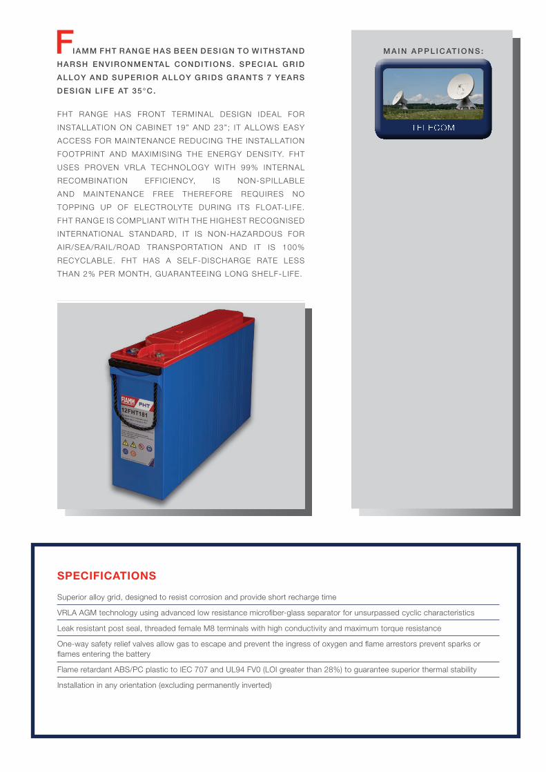
FIAMM FHT RANGE HAS BEEN DESIGN TO WITHSTAND
HARSH ENVIRONMENTAL CONDITIONS. SPECIAL GRID
ALLOY AND SUPERIOR ALLOY GRIDS GRANTS 7 YEARS
DESIGN LIFE AT 35°C.
FHT RANGE HAS FRONT TERMINAL DESIGN IDEAL FOR
INSTALLATION ON CABINET 19” AND 23”; IT ALLOWS EASY
ACCESS FOR MAINTENANCE REDUCING THE INSTALLATION
FOOTPRINT AND MAXIMISING THE ENERGY DENSITY. FHT
USES PROVEN VRLA TECHNOLOGY WITH 99% INTERNAL
RECOMBINATION EFFICIENCY, IS NON-SPILLABLE
AND MAINTENANCE FREE THEREFORE REQUIRES NO
TOPPING UP OF ELECTROLYTE DURING ITS FLOAT-LIFE.
FHT RANGE IS COMPLIANT WITH THE HIGHEST RECOGNISED
INTERNATIONAL STANDARD, IT IS NON-HAZARDOUS FOR
AIR/SEA/RAIL/ROAD TRANSPORTATION AND IT IS 100%
RECYCLABLE. FHT HAS A SELF-DISCHARGE RATE LESS
THAN 2% PER MONTH, GUARANTEEING LONG SHELF-LIFE.
SPECIFICATIONS
Superior alloy grid, designed to resist corrosion and provide short recharge time
VRLA AGM technology using advanced low resistance microfiber-glass separator for unsurpassed cyclic characteristics
Leak resistant post seal, threaded female M8 terminals with high conductivity and maximum torque resistance
One-way safety relief valves allow gas to escape and prevent the ingress of oxygen and flame arrestors prevent sparks or flames entering the battery
Flame retardant ABS/PC plastic to IEC 707 and UL94 FV0 (LOI greater than 28%) to guarantee superior thermal stability
Installation in any orientation (excluding permanently inverted)
Telecom
M A I N A P P L I C AT I O N S :
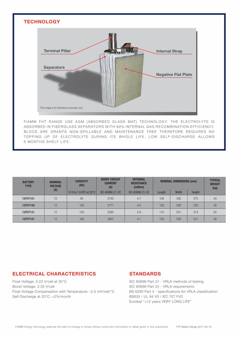
TECHNOLOGY
F I A M M F H T R A N G E U S E A G M ( A B S O R B E D G L A S S M AT ) T E C H N O L O G Y. T H E E L E C T R O LY T E I S A B S O R B E D I N F I B E R G L A S S S E PA R AT O R S W I T H 9 9 % I N T E R N A L G A S R E C O M B I N AT I O N E F F I C I E N C Y. B L O C S A R E G R A N T S N O N - S P I L L A B L E A N D M A I N T E N A N C E F R E E T H E R E F O R E R E Q U I R E S N O T O P P I N G U P O F E L E C T R O LY T E D U R I N G I T S W H O L E L I F E . L O W S E L F - D I S C H A R G E A L L O W S 6 M O N T H S S H E L F L I F E .
ELECTRICAL CHARACTERISTICS
Float Voltage: 2.23 V/cell at 35°CBoost Voltage: 2.35 V/cellFloat Voltage Compensation with Temperature: -2.5 mV/cell/°CSelf-Discharge at 20°C: <2%/month
STANDARDS
IEC 60896 Part 21 - VRLA methods of testingIEC 60896 Part 22 - VRLA requirementsBS 6290 Part 4 - specifications for VRLA classificationBS633 / UL 94 V0 / IEC 707 FV0Eurobat “>12 years VERY LONG LIFE”
Terminal Pillar Internal Strap
Separators
Negative Flat Plate
The image is for illustrative purposes only.
BATTERYTYPE
NOMINALVOLTAGE
(V)
CAPACITY (Ah)
SHORT CIRCUIT CURRENT
(A)
INTERNAL RESISTANCE
(mOhm)
NOMINAL DIMENSIONS (mm) TYPICALWEIGHT
(kg)10 H to 1.8 VPC at 20°C IEC 60896 21-22 IEC 60896 21-22 Length Width Height
12FHT101 12 95 2745 4.7 108 395 275 34
12FHT100 12 100 2771 4.6 126 558 230 40
12FHT151 12 150 2595 4.9 110 531 314 50
12FHT181 12 180 3057 4.1 126 558 321 58
FIAMM Energy Techology reserves the right to change or revise without notice any information or detail given in this publication FHT Battery Range_2017_09_19

youtube.com/user/FIAMMvideo
HeadquartersFIAMM Energy Technology S.p.A.Viale Europa, 7536075 Montecchio Maggiore (VI) - ItalyTel. +39 0444 709311Fax +39 0444 694178
A Hitachi Group Company
CERTIFICATIONS
I S O 9 0 0 1Q u a l i t y M a n a g e m e n t S y s t e m
I S O 1 4 0 0 1 E n v i ro n m e n t a l M a n a g e m e n t S y s t e m
O H S A S 1 8 0 0 1Wo r k p l a c e S a f e t y & H e a l t h
ACCESSORIES
R V S ( re m o t e v e n t i n g s y s t e m ) f o r a p p l i c a t i o n s w h i c h re q u i re re m o t e g a s s i n g
R a c k f o r b a t t e r y i n s t a l l a t i o n ( s t a n d a rd a n d s e i s m i c )
C a b i n e t s f o r b a t t e r y i n s t a l l a t i o n ( i n c l u d i n g e l e c t r i c a l p ro t e c t i o n s a n d d i s c o n n e c t i o n )
B a t t e r y m o n i t o r i n g s y s t e m s
5 10 200
Cha
rgin
g Vo
ltage
2.0
0
1.6
1.8
2.2
2.4[V/Cell][A]
[hours]
[%]
15
Voltage 100%50%
RechargedCapacity
100%50%
Current 100%50%
Cha
rgin
g C
urre
nt
Rec
harg
ed C
apac
ity
140
60
100
80
120
40
20
0
0.10 C10
0.05 C10
0
40°C
5°C
30°C 20°C
0 2 4 6 8 10 12 14 16 18 20
40
60
80
100The battery can be
used without refreshing charge
Refreshing charge at 2.4 Vpc for 24 hours (at 20-25°C) must be
applied as soon as possible.
Refreshing charge of 2.4 Vpc may be
insuf�cient to recover the battery capacity.
It is important to avoid this area
Storage Time (months)
Rem
aini
ng C
apac
ity (%
)
Battery Voltage and Charge Time for Standby Use (at 20°C) Capacity loss during storage at various temperatures
Discharge time (min)
Bat
tery
Vol
tage
(V/c
ell)
1.5
1.6
1.8
1.7
2.0
1.9
2.1
2.2
1 10 100 1.000 10.000
1.5 C
0.50 C1.0 C
0.37 C
0.10 C
DISCHARGE CuRvES at different current / final voltage (at 20°C)
TYPICAL CHARGE CuRvES STORAGE
The above discharge curves are typical. For more detailed information please see the specific product sheets.
Top Related