


Languages
Pages
Legal


7/25/2019 FAPT Ladder for PC-Operator Manual
http://slidepdf.com/reader/full/fapt-ladder-for-pc-operator-manual 1/302
Computer Numerical Control Products
GE Fanuc Automation
FAPT Ladder for PC
Operators Manual
B-66131EN/05 Japan 1995

7/25/2019 FAPT Ladder for PC-Operator Manual
http://slidepdf.com/reader/full/fapt-ladder-for-pc-operator-manual 2/302
Warnings and notices for
this publication
GFLE-003
Warning
In this manual we have tried as much as possible to describe all the variousmatters. However, we cannot describe all the matters which must not be done,or which cannot be done, because there are so many possibilities.
Therefore, matters which are not especially described as possible in thismanual should be regarded as “impossible”.
NoticeThis document is based on information available at the time of its publication. While efforts have
been made to be accurate, the information contained herein does not purport to cover all details or
variations in hardware or software, nor to provide every contingency in connection with
installation, operation, or maintenance. Features may be described herein which are not present in
all hardware and software systems. GE Fanuc Automation assumes no obligation of notice to
holders of this document with respect to changes subsequently made.
GE Fanuc Automation makes no representation or warranty, expressed, implied, or statutory with
respect to, and assumes no responsibility for accuracy, completeness, sufficiency, or usefulness of
the information contained herein. No warranties of merchantability or fitness for purpose shall
apply.
The following are Registered Trademarks of GE Fanuc Automation
CIMPLICITY® Genius®
The following are Trademarks of GE Fanuc Automation
Alarm Master
CIMSTAR
Field Control
Genet
Helpmate
LogicMaster Modelmaster
PowerMotion
ProLoop
PROMACRO
Series Five
Series 90
Series One
Series Six
Series ThreeVuMaster
Workmaster
© Copyright 1998 FANUC Ltd. Authorized Reproduction GE Fanuc Automation Europe S.A.
All Rights Reserved
No part of this manual may be reproduced in any form.
All specifications and designs are subject to change without notice.

7/25/2019 FAPT Ladder for PC-Operator Manual
http://slidepdf.com/reader/full/fapt-ladder-for-pc-operator-manual 3/302
CONTENTS
I. BASICS (NORMAL OPERATIONS)
1. OVERVIEW
......................................................
l-1
2. INSTALLATION
...................................................
1-5
2.1 Operating Environment
..........................................
1 - 6
2.1.1
PC9801 operating environment
...............
._
.............
1 - 7
2.1.2 IBM PC/AT operating environment
...........................
l-10
2.2 Installation Procedure
.......................................... l-11
3. ACTIVATION
....................................................
l-15
4. BASICOPERATION
.......................
..q
.....................
l-17
4.1 Menu Configuration
...........................................
l-17
4.2 Common System Operations
.....................................
l-19
4.3 Model Setting
................................................ l-21
5. OPERATION
....................................................
5.1 Editing
.....................................................
5.1 .l Title data editing
........................................
5.1.2 Ladder diagram editing
...................................
5.1.3 Symbol and comment editing
...............................
5.1.4 Message editing
........................................
5.1.5 I’0 module editing
.......................................
5.1.6 System parameter editing
.................................
5.2 Printout
....................................................
5.3 Compilation
.................................................
5.3.1 Operation
.............................................
5.3.2 Password set function
(PMCRAlRA3/RB3/RB4’RB5/RB6/RC3 RC4/NB NB2) .............
5.3.3 Changing the Order of Subprograms
.........................
5.3.4 It is possible to choose output data
(Symbol/Comment. Net comment) to ROM format file
.............
5.3.5 The list of source program
................................
5.3.6 DOS command
........................................
5.4 Decompilation
..............................................
5.4.1 Operation
............................................
5.4.2 Outputting to split files
...................................
5.4.3 Converting a step sequence program according to the model
.......
5.4.4 Merge ..............................................
5.5 Link
......................................................
l-22
l-22
l-25
l-26
l-60
l-68
l-70
l-73
l-85
1 - 94
l-95
l-99
1 -
103
l-103
l-105
l-109
l-110
l-110
l-112
1-113
1-113
l-116

7/25/2019 FAPT Ladder for PC-Operator Manual
http://slidepdf.com/reader/full/fapt-ladder-for-pc-operator-manual 4/302
5. 6 I nputi Output . . . . . . . . . . . . . . . . . . . . . . . . . . . . . . . . . . . . . . . . . . . . . . .
5. 6. 1
ROM writers (PMC writer, FA writer) . . . . . . . . . . . . . . . . . . . . . . . . .
5.6.2
Transfer to and from PMC-L/M (FANUC Series 0)
. . . . . . . . . . . . . . .
5.6.3
Transfer to and from PMC-P (FANUC Power Mate-MODEL A’B.‘C. E) . .
5.6.4 Transfer to and from PMC-N NA (FANUC Series 15MODEL A,
-MODELB) . . . . . . . . . . . . . . . . . . . . . . . . . . . . . . . . . . . . . . . . . .
56.5
input/Output for PMC-QA (FANUC SYSTEM F-MODEL D Mate)
. . . . .
5.6.6
Transfer to and from PMC-R series/PAl/PA3/NB QC
. . . . . . . . . . . . .
5.6.7
Memory card interface in the personal computer and memory card
. . .
5.6.8
Handy File + 3.5” floppy disk (MS-DOS format)
. . . . . . . . . . . . . . . . .
5. 6. 9
FLOPPY CASSETTE ADAPTER + 3.5” floppy disk (P-G format)
. . . . .
5.7 Mnemonic Editing . . . . . . . . . . . . . . . . . . . . . . . . . . . . . . . . . . . . . . . . . . . .
5.7.1
Conversion of a source program to a mnemonic file . . . . . . . . . . . . . .
5.7.2
Conversion of a mnemonic file to a source program . . . . . . . . . . . . . .
5.7.3 Mnemonic file format . . . . . . . . . . . . . . . . . . . . . . . . . . . . . . . . . . . .
5.7.4
Sample mnemonic files (single-format)
. . . . . . . . , . . . . . . . . . . . . . .
5.7.5
Sample mnemonic files (all-format) . . . . . . . . . . . . . . . . . . . . . . . . . .
5.7.6
The note if the step sequence function is selected when setting a model
5.7.7
User batch file execution
. . . . . . . . . . . . . . . . . . . . . . . . . . . . . . . . .
II. APPLICATIONS (NOTES ON THE PC ENVIRONMENT)
1. COMMON OPERATIONS FOR THE PC9801 AND IBM PC’AT
..................
2- l
1.1 Function for Transferring Data between the P-G and PC ..................
2- l
1 l l
Command input during startup
...............................
2- l
1.1.2
Communications settings
...................................
2- 2
1. 1. 3
Protocol ...............................................
2- 4
1.1.4
BUSY control ...........................................
2- 4
1.1.5
Data start and end codes
...................................
2- 5
1. 1. 6
Data conversion (return codes)
...............................
2- 5
1.1.7
Transmission and receive data
...............................
2- 5
1.1.8
Error detection and messages
...............................
2- 6
1. 1. 9
Error detection and handling
.................................
2- 7
1.2 Convert the PMC Type of Sequence Program ..........................
2- 8
1.2.1
Converting by system parameter editing
........................
2- 8
1.2.2
Convert with signal address converter
..........................
2- 9
1. 2. 3
Using data in a sequence program for another program
............
2-11
1.3 Standard Symbol Data
.........................................
2-11
1.4 Changing Printer Output Format
...................................
2-12
1.4.1
Changing the paper selection name
..........................
2-14
1.4.2
Setting the top margin
....................................
2-14
1.4.3
Setting the spacing between the LADDER net
...................
2-14
1. 4. 4
Setting the printer model and print paper
.......................
2-15
1.4.5 Setting the line spacing ...................................
2-16
1.4.6
Sett i ng
he left margin
....................................
2-16
l - 119
1-122
1-124
1-128
l- 131
1-134
l - 140
1-142
1-147
1-149
l - 150
l - 150
l - 152
1-153
1-157
1-166
l - 170
1-171

7/25/2019 FAPT Ladder for PC-Operator Manual
http://slidepdf.com/reader/full/fapt-ladder-for-pc-operator-manual 5/302
1.4.7 Setting the title of printout
.................................
2-19
1.4.8 Setting the cross-reference list output format guidance information
.... 2 - 19
1.4.9 Setting the cross-reference list output information
................ 2 - 20
1.4.10 Specifying the cross-reference list output format
................. 2 - 20
1.4.11 Setting the cross-reference list readiwrite coil guidance information ....
2-21
1.4.12 Specifying the cross-reference list linefeed
.....................
2-21
1.4.13 Specifying the cross-reference list page break
................... 2 - 21
1.4.14 Setting the output format guidance
........................... 2 - 22
1.4.15 Setting the output information
...............................
2-22
1.4.16 Setting the output format
..................................
2-22
1.4.17 Setting the read/write coil guidance
........................... 2 - 23
1.4.18 Setting line feed
........................................
2-23
1.4.19 Setting form feed
.......................................
2-23
III.THE STEP SEQUENCE FUNCTIONS
1. OVERVIEW
......................................................
3-l
1.1 WhatisaStepSequence?
.......................................
3-l
1.2 Programming with the Step Sequence Method
......................... 3 - 1
1.3 A Program Configuration Screen
...................................
3 - 1
1.4 The Configration of a Sequence Program
............................. 3 - 2
1.5 DataFlow
...................................................
3-3
2. SETTING A MODEL ................................................ 3-4
2.1 Operation
....................................................
3-4
3. EDITING
........................................................ 3-6
3.1 Basic Operation
...............................................
3 - 6
3.2 Creating a Step Sequence
.......................................
3 - 9
3.2.1
Creating a subprogram of the step sequence
.....................
3 - 9
3.2.2
Creating a step sequence program
...........................
3 - 10

7/25/2019 FAPT Ladder for PC-Operator Manual
http://slidepdf.com/reader/full/fapt-ladder-for-pc-operator-manual 6/302
APPENDIX
APPENDIX 1 DATA TRANSFER CABLES
..................................
Al - 1
APPENDIX 2 FUNCTION FOR OPERATING THE PMC-L/M WITH RAM
............
A2 - 1
APPENDIX 3 ERROR MESSAGES
......................................
A3 - 1
APPENDIX 4 MODULAR PROGRAMMING (PMC-RA3/RB3/RC3 ONLY)
............
A4 - 1
APPENDIX 5 BOOT SYSTEM OPERATING PROCEDURE (FOR THE FS20)
.........
A5 - 1
APPENDIX 6 MEMORY CARD COMPATIBILITY (FOR THE PMC-RAl RA3, NB, AND QC) A6 - 1
APPENDIX 7 CAUTIONS FOR USING THE O/S
.............................
A7- 1
APPENDIX 8 TOOL FOR CHANGING MESSAGE DATA (CHGMES)
...............
A8 - 1
APPENDIX 9 SOFTWARE VERSION TABLE
................................
A9 - 1
APPENDIX lOMANAGING A SOURCE PROGRAM
..........................
AlO- 1
APPENDIX 11 SYSTEM CONFIGURATION FILE “%%?‘oFLSET.CNF.‘.
.............
Al 1 - 1
APPENDIX 12 INQUIRY FORM
.........................................
A12- 1
7/25/2019 FAPT Ladder for PC-Operator Manual
http://slidepdf.com/reader/full/fapt-ladder-for-pc-operator-manual 7/302
I. BASICS
(NORMAL OPERATIONS)

7/25/2019 FAPT Ladder for PC-Operator Manual
http://slidepdf.com/reader/full/fapt-ladder-for-pc-operator-manual 8/302
1. OVERVIEW
1. OVERVIEW
This manual describes the software products listed below which are included in the FAPT LADDER
offline programming system for FANUC PMC sequence program generation. These software
products are designed to run on standard personal computers.
Personal
computer
Name Specification Remarks
JEC PC9801 FAPT LADDER PMC-L/M/P
A08B-9200-J500#JP For the NEC PC9801
FAPT LADDER PMC-N
A08B-9200-J501 #JP
Series and compatible
FAPT LADDER PMC-RB/‘RC A08B-9200-J502#JP machines (Japanese
language version)
BM PC/AT
FAPT LADDER PMC-UM/P A08B-9201 -JSOO#EN For IBM PC/AT and
FAPT LADDER PMC-N
A08B-9201-J501#EN compatible machines
FAPT LADDER PMC-RB/RC A08B-9201-J502#EN (English language version)
This manual explains procedures required to install, activate, and operate the software above that
are specific to the system designed for use with personal computers. For PMC operations and
how to create PMC sequence programs, refer to the manuals listed below.
FANUC PMC-MODEL K/UM P
Programming Manual (LADDER language) B-551 93E
FANUC PMC-MODEL N
Programming Manual (LADDER language) B-61013E
FANUC PMC-MODEL PA1 :PA3:RAl ‘RA2 RA3/RB’RB2 RB3iRB4 RBS’RBG;RC RC3’RC4 NB’NB2
Programming Manual (LADDER language) B-61 863E
Inquiry form
If you have any questions after reading this operator’s manual and the manuals listed above,
use the inquiry form attached at Appendix 12 to consult us the questions.
l-l

7/25/2019 FAPT Ladder for PC-Operator Manual
http://slidepdf.com/reader/full/fapt-ladder-for-pc-operator-manual 9/302
1. OVERVIEW
The following abbreviations are used in this manual for PMC models.
Abbreviations
PMC-UM P
* PMC-L
* PMC-M
* PMC-P
Pfk-N
PMC-R Series
* PMC-RAl _ *
* PMC-RA2 .-
* PMC-RA3
- PMC-RB
- PMCRB2
* PMC-RB3
- PMC-RB4
- PMC-RB5
* PMC-RB6
. PMC-RC
* PMGRC3
* PMCRC4
PMC-PA1
PMC-PA3
PMC-QA
PMC-QC
PMC-NA
PMC-NB
PMC-NB2
PMC Models
FANUC PMC-MODEL L
FANUC PMC-MODEL M
FANUC PMC-MODEL P
FANUC PMC-MODEL N
FANUC PMC-MODEL RAl
FANUC PMC-MODEL RA2
FANUC PMC-MODEL RA3
FANUC PMC-MODEL RB
FANUC PMC-MODEL RB2
FANUC PMC-MODEL RB3
FANUC PMC-MODEL RB4
FANUC PMC-MODEL RB5
FANUC PMC-MODEL RB6
FANUC PMC-MODEL RC
FANUC PMC-MODEL RC3
FANUC PM&MODEL RC4
FANUC PMC-MODEL PA1
FANUC PMC-MODEL PA3
FANUC PMC-MODEL QA
FANUC PMC-MODEL QC
FANUC PMC-MODEL NA
FANUC PMC-MODEL NB
FANUC PMC-MODEL NB2
1-2

7/25/2019 FAPT Ladder for PC-Operator Manual
http://slidepdf.com/reader/full/fapt-ladder-for-pc-operator-manual 10/302
1. OVERVIEW
The major functions of the software are listed below.
(1)
Sequence program input. display, and editing
(2)
Transmission to and from PMC (RAM), and PMC verification
(3)
ROM (EPROM, ROM cassette, and ROM modules) write, read, and verification
(4)
Sequence program print-out
Memory
card
. . . . .
c=e
,................................ > (-NC
RS232C
PMC
RS232C 3
FLOPPY
CASSETTE
/Handy File
Machine Tool
DVDO
‘
Personal computer
Floppy disk
NEC PC9801
IBM PC/AT
Input/Edit
sequence
program
Memory card
interface
Drawing
1-3

7/25/2019 FAPT Ladder for PC-Operator Manual
http://slidepdf.com/reader/full/fapt-ladder-for-pc-operator-manual 11/302
1. OVERVIEW
Operation flow for FAPT LADDER activation
Prepare personal computer. MS-DOS, and FAPT LADDER
+
Install MS-DOS
4
Create directory for FAPT LADDER
1
Install FAPT LADDER
+
Install device drivers
@et CONFIG.SYS and AUTOEXECBAT)
J.
Reset personal computer
Activate FAPT LADDER
Set model (PMC)
Operations includinq editing
J/
End?
JI
Yes
Reference chapter/section
Section 2.2
- Section 2.1
- Section 5.6
- Chapter 3
- Section 4.3
- Chapter 5
Terminate FAPT LADDER
l-4

7/25/2019 FAPT Ladder for PC-Operator Manual
http://slidepdf.com/reader/full/fapt-ladder-for-pc-operator-manual 12/302
2. INSTALLATION
2. INSTALLATION
FAPT LADDER software is stored on the floppy disks
listed below. Before the system can be
used, the contents of these system floppy disks must be
written to a hard disk;
the software cannot
be run directly from the floppy disks. To install the system on a hard disk, the user needs to be
familiar with the hardware and software of his or her personal computer, particularly with basic MS-
DOS command operation and files such as CONFIG.SYS and AUTOEXEC.BAT.
The names of the floppy disks are listed below.
FAPT LADDER PMC-L;M:P system floppy disk
Vols.1 and 2
FAPT LADDER PMC-L”module floppy disk
FAPT LADDER PMC-M module floppy disk
A08B-9200-J500 #JP (PC9801)
A08B-9201 -J500 #EN (IBM PC/AT)
A08B-9200-J600 #JP (PC9801)
A08B-9201-J600 #EN (IBM PCAT)
A08B-9200-J601 #JP (PC9801)
A08B-9201-J601 #EN (IBM PC/AT)
FAPT LADDER PMC-M (MMC) module floppy disk
A08B-9200-J602 #JP (PC9801)
A08B-9201-J602 #EN (IBM PC’AT)
FAPT LADDER PMC-N’NAQA system floppy disk
A08B-9200-J501 #JP (PC9801)
Vols.1, 2, and 3
A08B-9201-J501 #EN (IBM PC’AT)
FAPT LADDER PMCRAlIRA2IRA3:RBiRB2/RB3/RB4/RC A08B-9200-J502 #JP (PC9801)
/RC3/RC4/PAl PAYQCNB system floppy disk
A08B-9201 -J502 #EN (IBM PC/AT)
Vols. 1, 2, and 3
FAPT LADDER PMC-RAl IRA2iRA3;PAl iPA module
floppy disk
FAPT LADDER PMC-RB1RB2’RB3.‘RB4’RC’RC3.1RC4
module floppy disk
FAPT LADDER PMC-QC module floppy disk
FAPT LADDER PMC-NB module floppy disk
A08B-9200-J603 #JP (PC9801)
A08B-9201 -J603 #EN (IBM PC’AT)
A08B-9200-J604 #JP (PC9801)
A08B-9201-J604 #EN (IBM PC’AT)
A08B-9200-J605#JP (PC9801)
A08B-9201 -J605#EN (IBM PCAT)
A08B-9200-J606#JP (PC9801)
A08B-9201-J606#EN (IBM PC AT)
l-5
7/25/2019 FAPT Ladder for PC-Operator Manual
http://slidepdf.com/reader/full/fapt-ladder-for-pc-operator-manual 13/302
2. INSTALLATION
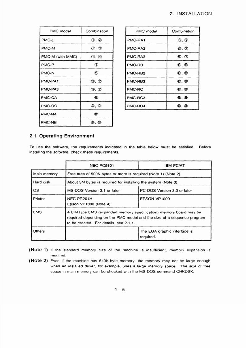
2.1 Operating Environment
PMC model Combination
PMC-L
0.8
PMC-M
@, @
PMC-M (with MMC)
0. @I
PMC-P
0
PMC-N
@
PMC-PA1
@, @
PMC-PA3
0, ZJ
PMC-QA
@
PMC-QC
43 @
?MC-NA
6J
‘MC-NB
0, @
PMC model
Combination
PMC-RAl
0, QJ
PMC-RA2
@, @
PMC-RA3
@. QJ
PMC-RB
@, @
PMC-RB2
@, @
PMC-RB3
@, @
PMC-RC
0, @
PMC-RC3
0, @
PMC-RC4
8, @
To use the software, the requirements indicated in the table below must be satisfied. Before
installing the software, check these requirements.
Main memory
Hard disk
OS
Printer
EMS
Others
(Note
1)
(Note 2)
NEC PC9801 IBM PC/AT
Free area of 500K bytes or more is required (Note 1) (Note 2).
About 3M bytes is required for installing the system (Note 3).
MS-DOS Version 3.1 or later
PC-DOS Version 3.3 or later
NEC PR20lH
EPSON VP1 000
Epson VP1000 (Note 4)
A LIM type EMS (expanded memory specification) memory board may be
required depending on the PMC model and the size of a sequence program
to be created. For details, see 2.1.1.
The EGA graphic interface is
required.
If the standard memory size of the machine is insufficient, memory expansion is
required.
Even if the machine has 640K-byte memory, the memory may not be large enough
when an installed driver. for example, uses a large memory space. The size of free
space in main memory can be checked with the MS-DOS command CHKDSK.
l-6

7/25/2019 FAPT Ladder for PC-Operator Manual
http://slidepdf.com/reader/full/fapt-ladder-for-pc-operator-manual 14/302
2. INSTALLATION
(Note 3) In addition, an area for storing sequence program data is required.
(Note 4)
To use the Epson VP1000 with an NEC PC9801, a program modification is required.
For details, see Section 1.2 in Part II.
2.1.1 PC9801 operating environment
(1) CONFIG.SYS, AUTOEXEC.BAT
When starting MS-DOS, the user needs to install the following device drivers:
RSDRV.SYS
PRINT.SYS
Add the lines indicated below to CONFIG.SYS.
RSDRV.SYS and PRINT.SYS are assumed to be under the directory named gSDEV on drive A.
DEVICE=A:$(DEVyRSDRV.SYS
DEVICE=A:yDEV'1CPRINT,SYS
(Note) When you are using a memory card adapter, set CONFIG.SYS referring to the
operator’s manual for the memory card adapter.
(2)
Using the expanded memory
The expanded memory specification (EMSXMS) memory can be used with the system as a
work area for a sequence program. EMSXMS memory allows a larger sequence program to
be used. (An EMS memory size of 256K bytes or more allows 24000 or more steps to be
edited.)
If EMSXMS memory is not used, a sequence program of up to about 21840 steps can be
handled when the main memory has a free area of 570K bytes.
Ladder diagram editing cannot output drawings if a free area sufficient for 16000 steps cannot
be allocated in main memory due to the space taken up by resident device drivers. In this
case, EMS memory is required.
FANUC has confirmed that the setting described below ensures normal operation.
MS-DOS Version 3.38 (for the PC-9801 Series)
Machine with a 80386:80386SX CPU
Specify the statement below as the first DEVICE statement of the CONFIG.SYS file. Each
device driver is assumed to be under the directory named DEV on drive A.
(Note)
When an EMS board and EMS device driver are used, change the CONFIGSYS file
according to the manufacture’s manual.
l-7

7/25/2019 FAPT Ladder for PC-Operator Manual
http://slidepdf.com/reader/full/fapt-ladder-for-pc-operator-manual 15/302
2. INSTALLATION
Expanded memory (EMS)
Extended memory (XMS)
EMS and/or XMS of 4 Mbytes or more
(recommended) (Kate
1)
* Better to include EMS of 256 kbyte
or more
(Note 2)
Note 1) The quantity of the EMS and XMS memory effects on the performance to handle
Symbol data and Net comment.
Please prepare enough EMS or XMS memory
specially for Symbol data or Net comment of large number.
Note 2)
At the system with EMS less than 256 kbytes, the maximum number of steps which
FAPT LADDER can handle may be restricted. Please prepare 256 kbytes or more
EMS if possible.
About size of EMS and XMS memory to be used:
Although FAPT LADDER runs with no EMS nor XMS, enough size of EMS and/or XMS memory
according to the source program to handle will be necessary for better performance.
1)
2)
3)
EMS memory for Ladder
sequence program
FAPT LADDER uses EMS memory for Ladder sequence program if available.
When no EMS memory is found,
the convenGonal memory is used, and the size of
conventional memory may restrict the number of steps able to be edited.
Ladder sequence program occupies 256 kbyte of EMS, regardless of the type of PMC, or
the size of the ladder sequence program to edit.
EMS
and
XMS
memory for Symbol & Comment data
FAPT LADDER uses EMS and/or XMS memory for Symbol & Comment data if available.
When neither of them are available, FAPT LADDER will make temporary file on the hard
drive, and processing large number of Symbol & Comment data may be slower.
About 200 kbytes of EMS or XMS memory are used for every 1,000 Symbol data.
EMS
and
XMS
memory for Net comment
For Net comment, FAPT LADDER also uses EMS and/or XMS memory, or temporary file
as same as Symbol & Comment data.
About 200 to 300 kbytes of
EMS or XMS
memory are used
for every 1,000 Net comments.
(3) Using a Japanese
language input
FEP
FAPT LADDER for
PC9801
allows comments in Japanese to be entered on the symbol and
comment editing screen. (See Section 51.3.)
For Japanese language input, a front-end processor (FEP) for Japanese language input is
required.
For information about the installation and operation of an FEP, see the relevant
manual.
1-8

7/25/2019 FAPT Ladder for PC-Operator Manual
http://slidepdf.com/reader/full/fapt-ladder-for-pc-operator-manual 16/302
2. INSTALLATION
The following Japanese language input FEPs can be used:
Supplier
NEC
Driver name
NECAlKl. DRV
NECAIK2. DRV
Memory size required
About 130K bytes
Remarks
Al step-by-step conversion
Al multiple-block conversion
Step-by-step conversion
Multiple-block conversion
NECDIC. DRV
Just Systems ATOKGA. SYS
ATOKGB. SYS
About 40K bytes
Single-block conversion
About 100K bytes ATOKG
ATOK7A. SYS
ATOK7B. SYS
About 115K bytes
ATOK
When the EMS is used
Main : 50K bytes
EMS : 64K bytes
1
Note the following points on Japanese language input:
(a)
(W
(c)
60
09
When a Japanese language input FEP is activated (in the Japanese language input mode),
the Japanese language input FEP displays data on a section of the screen. As a result, the
FAPT LADDER screen may temporarily be in disarray. However, the FAPT LADDER
screen returns to normal when Japanese language input is completed (Japanese language
input mode is terminated).
When a comment is entered using only Japanese, up to 14 characters can be entered.
A comment entered in Japanese can be displayed on the editing screen or printed out, but
cannot be written into a ROM cassette or transferred to the PMC. At compile time, a
message is output indicating this restriction and all Japanese characters are converted to
blanks. Note, however, that sequence program operation is not affected.
A Japanese language input FEP is installed as a resident driver in the system. This means
that memory available to FAPT LADDER is reduced accordingly. Check that the size of
memory usable for FAPT LADDER is 500K bytes or more to allow FAPT LADDER
execution.
Editing alone can be performed without installing PRINT.SYS and RSDRV.SYS in order to
allocate a free area of 500K bytes. Note that when FILES or BUFFERS is specified in
CONFIG.SYS. a main memory size of 1K bytes is used per file (buffer) specified. Make
adjustments as required.
A Japanese language input FEP can also be installed with ADDDRV and DELDRV by using
a subprocess after calling COMMAND.COM in user batch execution.
An example is provided below.
l - 9
7/25/2019 FAPT Ladder for PC-Operator Manual
http://slidepdf.com/reader/full/fapt-ladder-for-pc-operator-manual 17/302
2. INSTALLATION
2.1.2
(1)
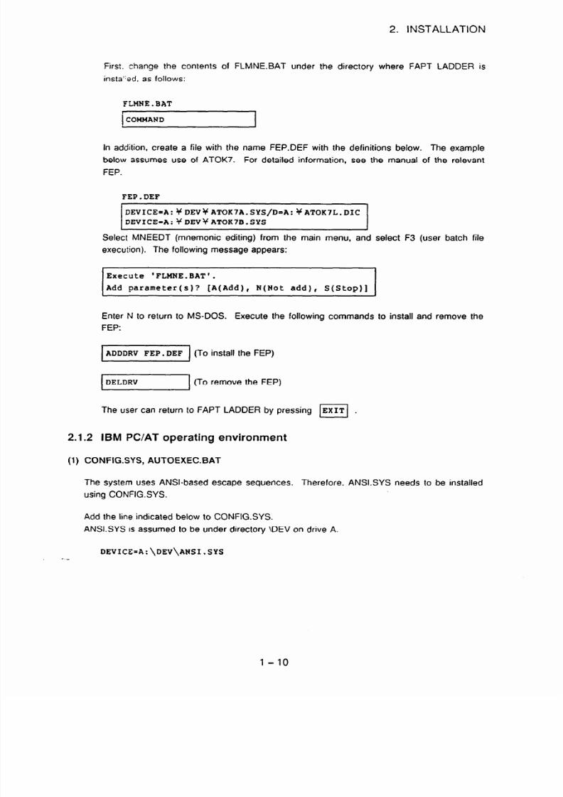
First. change the contents of FLMNE.BAT under the directory where FAPT LADDER is
insta”ed, as follows:
FLMNE. BAT
r
OMMAND
In ddition, create a file with the name FEP.DEF with the definitions below. The example
below assumes use of ATOK7. For detailed information, see the manual of the relevant
FEP.
FEP.DEF
DEVICE=A:YDEV+ATOK7A.SYS/D=A:+ATOK7L.DIC
DEVICE=A:YDEV)CATOK7B.SYS
>
Select MNEEDT (mnemonic editing) from the main menu, and select F3 (user batch file
execution). The following message appears:
Execute 'FLMNE.BAT'.
Add
parameter(s)?
[A(Add), N(Not add), S(Stop)]
Enter N to return to MS-DOS. Execute the following commands to install and remove the
FEP:
ADDDRV FEP.DEF
DELDRV
1
(To install the FEP)
(To remove the FEP)
The user can return to FAPT LADDER by pressing Fi .
IBM PC/AT operating environment
CONFIGSYS, AUTOEXEC.BAT
The system uses ANSI-based escape sequences.
Therefore, ANSI.SYS needs to be installed
using CONFIG.SYS.
Add the line indicated below to CONFIG.SYS.
ANSI.SYS is assumed to be under directory \DEV on drive A.
DEVICE=A:\DEV\ANSI.SYS
l - 10

7/25/2019 FAPT Ladder for PC-Operator Manual
http://slidepdf.com/reader/full/fapt-ladder-for-pc-operator-manual 18/302
2. INSTALLATION
(2)
Using EMS
The expanded memory specification (EMS) memory can be used with the system as a work
area for a sequence program. The EMS memory allows a larger sequence program to be
used. (An EMS memory size of 256K bytes or more allows 24000 steps to be edited.)
If EMS memory is not used, a sequence program of up to about 21840 steps can be handled
when the main memory has a free area of 570K bytes.)
Ladder diagram editing cannot be started if a free area sufficient for 16000 steps cannot be
allocated in main memory due to the space taken up by resident device drivers. In this case,
EMS memory is required.
FANUC has confirmed that the setting described below ensures normal operation.
MS-DOS Version 4.0
Specify the statements below as the first DEVICE statements of the CONFIG.SYS file. Each
device driver is assumed to be under directory \DEV on drive A.
DEVICE=A:\DEV\XMAEM.SYS
DEVICE=A:\DEV\XMA2EMS.SYS FRAME=COOO
2.2 Installation Procedure
An installation batch file is used to install the programs on the system and module floppy disks.
(See (3))
Note that there are two different installation procedures. They are selected according to the type
and edition of the system.
0 Installation of ordinary files (see item (1) for the procedure.)
The programs on the following system and module floppy disks are distributed in ordinary
file format.
-
PMC-L/M/P system floppy disk (AOSB-9200/9201-J500) editions 06.1 and earlier
.
PMC-N system floppy disk (A08B-920019201 -JSOl)
.
PMC-RB RC system floppy disk (A08B-9200/9201 -J502) editions 07.1 and earlier
*
All module floppy disks
@ Installation of compressed files (see item (2) for the procedure.)
The programs on the following system and floppy disks are distributed in compressed file
format.
*
PMC-L/M/P system floppy disk (AOSB-9200/9201-J500) editions 06.2 and earlier
*
PMC-RBRC system floppy disk (AO8B-9200/9201-J502) editions 08.0 and earlier
Note 1)
The installation procedure of the programs on each floppy disk is subject to change.
Before starting installation, refer to a README.DOC file (if there is one). If there is no
README.DOC, use the ordinary file format installation procedure
(1).
1-11
7/25/2019 FAPT Ladder for PC-Operator Manual
http://slidepdf.com/reader/full/fapt-ladder-for-pc-operator-manual 19/302
2. INSTALLATION
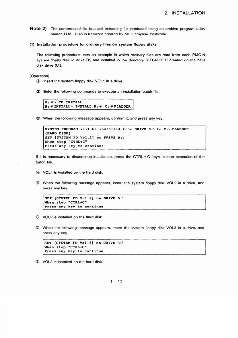
Note 2)
The compressed file is a self-extracting file produced using an archive program utility
named LHA. LHA is freeware created by Mr. Haruyasu Yoshizaki.
(1)
Installation procedure for ordinary
files on system floppy disks
The following procedure uses an example in which ordinary files are read from each PMC-N
system floppy disk in drive B:, and installed in the directory Y FLADDER created on the hard
disk drive (C:).
[Operation]
Insert the system floppy disk VOLl in a drive.
Enter the following commands to execute an installation batch file.
B:Y> CD INSTALL
B:YINSTALL> INSTALL B:Y C:+FLADDER
0
When the following message appears, confirm it, and press any key.
SYSTEM PROGRAM will be installed from DRIVE B:\ to C:\ FLADDER
(HARD DISK)
SET [SYSTEM FD Vol.11 on DRIVE B:\
When stop "CTRL+C"
Press any key to continue
If it is necessary to discontinue installation, press the CTRL + C keys to stop execution of the
batch file.
VOLI is installed on the hard disk.
When the following message appears, insert the system floppy disk VOL2 in a drive, and
press any key.
SET [SYSTEM FD Vol.21 on DRIVE B:\
When stop "CTRLtC"
Press any key to continue
VOL2 is installed on the hard disk.
When the following message appears, insert the system floppy disk VOL3 in a drive, and
press any key.
SET [SYSTEM FD Vol.31 on DRIVE B:\
When stop "CTRLtC"
Press any key to continue
VOL3 is installed on the hard disk.
1-12

7/25/2019 FAPT Ladder for PC-Operator Manual
http://slidepdf.com/reader/full/fapt-ladder-for-pc-operator-manual 20/302
2. INSTALLATION
(2)
9 The following message
appears.
Installation procedure for compressed files on system floppy disks
The following procedure uses an example in which ordinary files are read from each PMC-
RB.‘RC system floppy disk in drive B:, and installed in the directory Y FLADDER created on the
hard disk drive (A:).
[Procedure ]
Note
Note
Insert the system floppy disk VOLl in a drive.
Enter the following commands to execute an installation batch file.
I
:Y> CD INSTALL
B:YINSTALL> INSTALL 9: A:YFLADDERY
I
1)
When specifying the files to be installed, enter only their drive name; do not specify a
directory (that is, do not enter 4h .
2)
When specifying the directory in which the system is to be installed, suffix it with
Y .
When the following message appears, confirm it. and press any key.
SYSTEM PROGRAM will be installed from DRIVE B:\ to A:\ FLADDER
(HARD DISK)
SET [SYSTEM FD Vol.11 on DRIVE B:\
When stop "CTRL+C"
Press any key to continue
If it is necessary to discontinue installation, press the CTRL + C keys to stop execution of the
batch file.
VOLl is installed on the hard disk.
When the following message appears, insert the system floppy disk VOL2 in a drive, and
press any key.
SET [SYSTEM FD Vol.21 on DRIVE B:\
When stop "CTRLtC"
Press any key to continue
VOL2 is installed on the hard disk.
1-13

7/25/2019 FAPT Ladder for PC-Operator Manual
http://slidepdf.com/reader/full/fapt-ladder-for-pc-operator-manual 21/302
2. INSTALLATION
When the following message appears. insert the system floppy disk VOL3 in a drive, and
press any key.
SET [SYSTEM FD Vo1.3) on DRIVE B:\
When stop "CTRL+C"
Press any key to continue
@I VOL3 is installed on the hard disk.
@I The following message appears.
(End/
(3) Installation batch files
The following table lists the installation batch files and their directories.
File name
Directory
@ PMC-L/M/P system floppy disk LMPINSTSAT
Ic INSTALL
8 PMC-L module floppy disk LINST.BAT
Y
$J PMC-M module floppy disk
MINST.BAT
Y
@ PMC-M (MMC) module floppy disk MMINSTBAT
gc
@J PMC-NINAQA system floppy disk INSTALL.BAT +J NSTALL
@ PMC-
INSTALL.BAT
qC NSTALL
RA~/RA~J’AA~RB:‘RB~;RBYRB~/‘RC~RC~ RC~/PA
1 PA3IQCINB system floppy disk
(3 PMC-RAl RA2IRAS/PAl IPA3 module floppy disk
RA12lNST.BAT Y INSTALL
EMC-RB RB2/RB3;RB4IRCIRC3iRC4 module
RBRCINST.BAT
Y INSTALL
floppy disk
?) PMC-QC module floppy disk
QCINST.BAT
Y INSTALL
I@ PMC-NB module floppy disk NBINST.BAT
gC NSTALL
(Note) Systems for different PMC models can be installed in the same directory. However,
restrictions may be placed depending on the edition of the software. See Appendix
9 for details. For systems that cannot be installed in the same directory, install them
in separate directories.
1
- 14
7/25/2019 FAPT Ladder for PC-Operator Manual
http://slidepdf.com/reader/full/fapt-ladder-for-pc-operator-manual 22/302
3. ACTIVATION
3. ACTIVATION
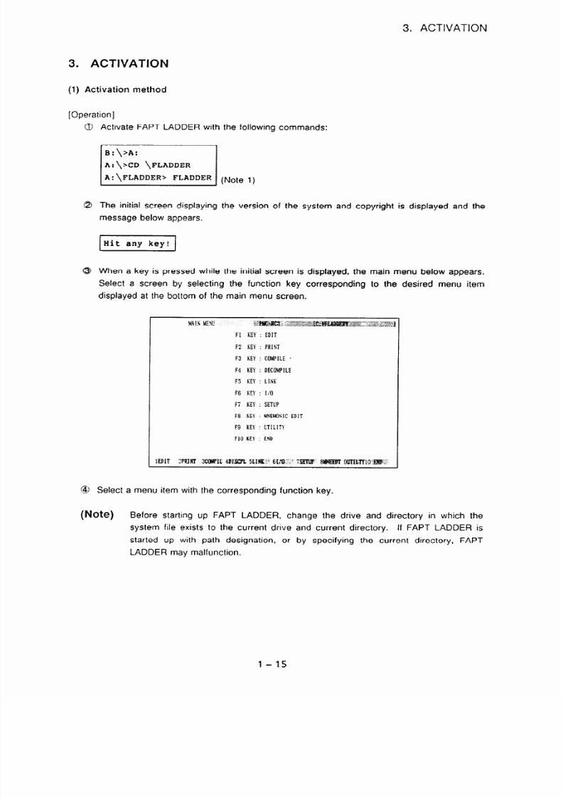
(1) Activation method
[Operation]
Activate FAPT LADDER with
the following commands:
B:\>A:
A:\xD \FLADDER
A: \FLADDER> FLADDER
(Note
1)
The initial screen displaying the version of the system and copyright is displayed and the
message below appears.
When a key is pressed while the initial screen is displayed, the main menu below appears.
Select a screen by selecting the function key corresponding to the desired menu item
displayed at the bottom of the main menu screen.
Fi KEY : SETUP
F8 KEY : MNEMONI C DI T
F9 KEY : UT[Ll Tt
Fl O KEY : END
Select a menu item with the corresponding function key.
(Note)
Before starting up FAPT LADDER, change the drive and directory in which the
system file exists to the current drive and current directory. If FAPT LADDER is
started up with path designation, or by specifying the current directory, FAPT
LADDER may malfunction.
1-15

7/25/2019 FAPT Ladder for PC-Operator Manual
http://slidepdf.com/reader/full/fapt-ladder-for-pc-operator-manual 23/302
3. ACTIVATION
Reference:
When an FL.BAT has been created in the directory for which path control is set,
FAPT LADDER can be activated by just typing FL and pressing the [RETURN]
key. An example of a batch file is provided below.
FL.BAT
ECHO OFF
A:
(Moves to the drive where the system files are installed.)
cD \FLADDER
(Moves to the directory where the system files are installed.)
FLADDER
(2)
Termination method
[Operation]
0 Select [END] from the main menu, or press the < ESC > key to return to the initial screen.
Then the following message appears:
END? (Y:END, 0THER:RESllME MENU)
8 Enter Y to return to the MS-DOS command mode. Enter N to return to the main menu.
l-16

7/25/2019 FAPT Ladder for PC-Operator Manual
http://slidepdf.com/reader/full/fapt-ladder-for-pc-operator-manual 24/302
4. BASIC OPERATION
4. BASIC OPERATION
4.1 Menu Configuration
The configuration of the menu screens displayed by the system are shown below.
MS-DOS
$- 4
initial screen
f 4
Main menu-
Fl
Edit
“’
itle data
Ladder diagram
Symbol and comment
Message
I/O module
System parameter
Execution
l-Setting
qz[TEXEC
Compression (PMC-R seriesKXiNB)
c
(PMC-N/NA/RC/RC3 QC4;QC/NB)
LPASCAL (PMC-N, NA)
-PMC writer, FA writer Read
Write
Verification
Blank
check
-PMC
-E
Download
Upload
Comparison
-Handy file/Floppy cassette adapter
-Memory card
(Note 1)
The format of the source program of this system is different from that of FAPT
LADDER for the P Series. Thts system uses the mnemonic edit function (F8) to edit a
file having the format of FAPT LADDER for the P Series.
(Note 2)
An object file has the ROM format of FAPT LADDER for the P Series. This system
reads a sequence program created by the P Series In the ROM file format. The format
of the floppy disk must be converted.
1-17

7/25/2019 FAPT Ladder for PC-Operator Manual
http://slidepdf.com/reader/full/fapt-ladder-for-pc-operator-manual 25/302
Diagram of relationships among the functions of the system
P-G -
FAPT
LADDER
- . . .
i Source i
; format
:s
: program i
: . . . .
. . . . . .
;
ROM ;
; format
:4
: program I
: . . . .
FAPT
PASCAL -
. . .
: PASCAL ;
: load
:-
:module i
. . . .
U-inch
ffOPPY
3.5inch
ffOPPY
-+I+
35inch
ffOPPY
- PC9801 - IBM-PC/AT
- FAPT LADDER
Edit
Setup
qzq+J4
ASC format
FLOAD98 IFLOADAT
+q+-+
Binary format
II
I
I
FLPGMS
k-1 Q I +
1 I
Binary format
ASC format
v ::
Communication by FEZ-2324
(Refer to Appendix 1 for cables)
fg-pii?-~-
Q-l_),
3.5inch
ff
PPY
CNC -
Memorv

7/25/2019 FAPT Ladder for PC-Operator Manual
http://slidepdf.com/reader/full/fapt-ladder-for-pc-operator-manual 26/302
4. BASIC OPERATION
4.2 Common System Operations
The operations described below are basic operations applicable to all screens.
(1)
Function keys
When the menu items shown below are displayed in reverse video, the user can select the
desired menu item by pressing the corresponding function key.
.:,:.. ‘j’., .j’.,
, ;z:,i,:lE D,T,i,j,I:(
j; :... ..:. ‘j. ;::i,:
pR,$& )j:..:::::; :.:_. ./ .::.?::is z
3 :;C*MP,i..: 4 j .&&...y s :;.“:;&
:y ; fj&“:‘:‘:q ,
y:)):., .., :,.: ::::..::
:.: ::...: .j,“. .,, ::: ;;:‘.
;::.;&“p~:., * .;&JE+
9
,
:,:
: :. ::
5 :.>::;:;;g( +j ,,
,,
WI
PI
F31
IF41
WI F61
( F , ]
WI
WI IF101
(2)
Escape key
The escape key <ESC> has the same effect as selecting [END] with the function key. The
escape key terminates the current screen then returns the display to the previous screen in the
menu hierarchy.
(3)
Cursor keys
The
cursor keys < t >, < 1 >, < + >, and < + > are used to move the cursor to
select input items.
When two or more cursors can be used on a single screen, the second or subsequent cursor
can be moved by pressing the <SHIFT> key together with the < + > or -z -+ > key.
(4)
Scroll
keys
The scroll keys <ROLL UP> and <ROLL DOWN > scroll the screen up (to display the
previous one page) and scroll the screen down (to display the next one page), respectively (for
the PC9801).
The scroll keys <PAGE DOWN > and <PAGE UP> display the next page and the previous
page, respectively (for the IBM PC/AT).
(5)
[INS]
key
This key switches between the overwrite mode c 0 > and insert mode -z I >.
(9)
[HELP] key
When the < HELP > key is pressed, help information may be output for the specified item.
1-19

7/25/2019 FAPT Ladder for PC-Operator Manual
http://slidepdf.com/reader/full/fapt-ladder-for-pc-operator-manual 27/302
4. BASIC OPERATION
(7) Status line
A status line is displayed at the top of the screen.
ain
menu
PMC-RB2 <O>[A::FLADDER
1
(8)
t-
Item name
t
Model currently selected
currently selected
L
Current
directory name
Edit mode (overwritefinsert)
(Note) The indications on the key tops may slightly vary from the descriptions of this
manual. depending on the personal computer used.
Pop-up menu
When the following pop-up menu appears, the desired process
the three methods described below.
can be selected using any of
The file already exists.
Fl Update
F2 Quit
F3 Append
1)
2)
3)
Cursor movement
To select an item, press the cursor key < ? > or c 1 >, such that the item to be selected
is displayed in reverse video. Then, pressing the <RETURN> key selects that item.
Function key
A function key is indicated at the left of each item. To select an item, press the
corresponding function key.
Command name
An uppercase letter in (usually, the initial of) an item name is the command name. In the
above case, pressing the letter key -z U >, <Cl>, or <A> can select the Update. Quit, or
Append command, respectively.
l-20

7/25/2019 FAPT Ladder for PC-Operator Manual
http://slidepdf.com/reader/full/fapt-ladder-for-pc-operator-manual 28/302
4. BASIC OPERATION
4.3
Model Setting
In this case, the user needs to select the PMC model by selecting [SETUP] before selectrng
another menu item. This setting, once executed, is preserved (i.e. setup need not be repeated).
[Operation]
Select [SETUP].
The setup menu is displayed. (The screen is of PMC-R08.0 version)
PUCM
PICRA?
PUCRA3
PUGRB
pcuc;;;
PUCRB4
PICRB4 (STEP Sp
PMCRC
*PWCRC3
PVCAC4
PVCRC4 (STEP SW
PUCPA
PUCPA3
PVCPC
PVCNB
Select the PMC model using the arrow keys.
Press the <RETURN > key. Then the following message appears and the model name
displayed in the status line changes.
Setup completed.
Select [END].
The display returns to the setup menu screen.
Select [END].
The display returns to the main menu screen.
(Note)
When PMC-NA is used, select PMC-N (l/O) on the above screen.
l-21

7/25/2019 FAPT Ladder for PC-Operator Manual
http://slidepdf.com/reader/full/fapt-ladder-for-pc-operator-manual 29/302
5. OPERATION
5. OPERATION
5.1 Editing
The source file of a sequence program is edited.
(1) Start
[Operation]
0 Select [EDIT] from the main menu indicated below.
Mm WC>
~~~~~~~~~~~~~~\~~~~~~~~~~ .:’ j ; >&:j
Fl KEY
EDI T
F2 KEY : PRI NT
F3 KEY : COMPI LE
F4 KEY : OECO?kPl LE
Fj KEY : LI NK
F6 KEY : I / O
Fi KEY : SETUP
FB KEY : MNEMONI C DI T
F9 KEY : UTI LI TY
F10 KEY : END
@ The following source file name input screen is displayed:
l-22
7/25/2019 FAPT Ladder for PC-Operator Manual
http://slidepdf.com/reader/full/fapt-ladder-for-pc-operator-manual 30/302
5. OPERATION
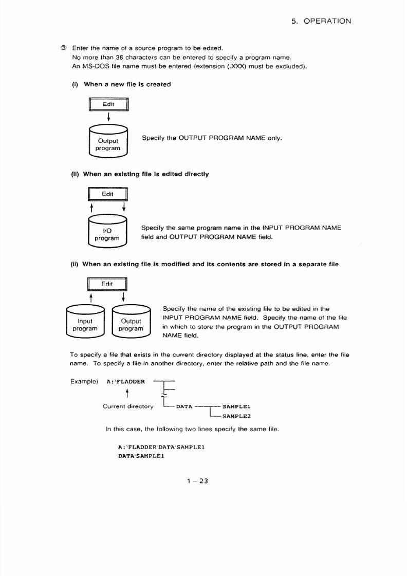
6 Enter the name of a source program to be edited.
No more than 36 characters can be entered to specify a program name.
An
MS-DOS
file name must be entered (extension (.xXx) must be excluded).
(i) When a new file is created
+
6
utput
Specify the OUTPUT PROGRAM NAME only.
program
(ii) When an existing file is edited directly
6
/O
Specify the same program name in the INPUT PROGRAM NAME
program
field and OUTPUT PROGRAM NAME field.
(ii) When an existing file is modified and its contents are stored in a separate file
I=7
input
nrnnram
Specify the name of the existing file to be edited in the
INPUT PROGRAM NAME field. Specify the name of the file
, y’vy’““’ ,
in which to store the program in the OUTPUT PROGRAM
< 2 L-2 NAME field.
To specify a file that exists in the current directory displayed at the status line, enter the file
name. To specify a file in another directory, enter the relative path and the file name.
Example) A : iFLADDER ‘7
t
-IT
Current directory
L
DATA ‘- SAMPLE1
i-- SAMPLE2
In this case, the following two lines specify the same file.
A:‘FLADDER’DATA’SAMPLEl
DATA’sAMPLE
l-23
7/25/2019 FAPT Ladder for PC-Operator Manual
http://slidepdf.com/reader/full/fapt-ladder-for-pc-operator-manual 31/302
5. OPERATION
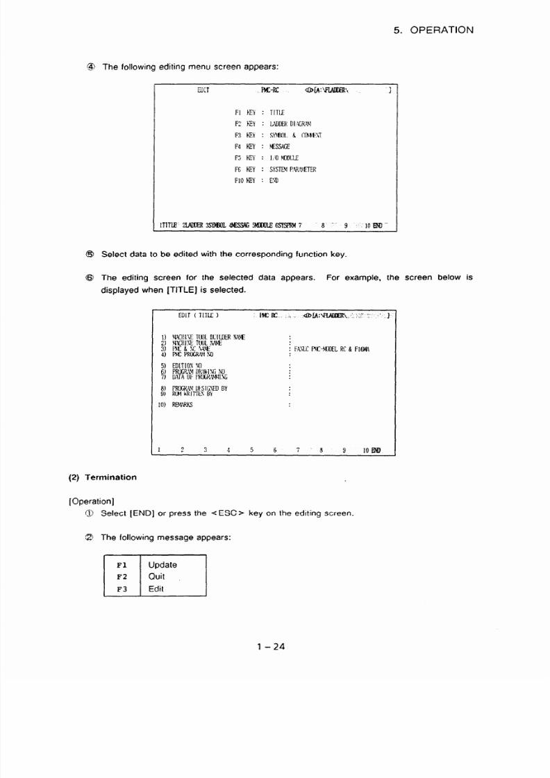
@ The following editing menu screen appears:
ED T
i x-x Q NA: wADI ; i R\
I
FI kEY : TI TLE
I ?? RY : LWDEK DI %R+
F3 m :
SMKI L 6 CONEI I T
F4 KFI : , WSAGE
F5 KEY :
I , ; 0I DLLE
FE hEY :
SYSTMP. J &WTER
Fl O kEY : E l u
($3 Select data to be edited with the corresponding function key.
$3 The editing screen for the selected data appears.
For example, the screen below is
displayed when [TITLE] is selected.
EDIT TITLL : fPf.z-fc \\ ,slb~:‘at. :\ :’ :: ” f
51 EDI TI OS O
6) PROCRMI l l ~~ hl V60
7) MT\ OF I ' RO(; f f i l WG
8) PRG- XI I HI CSEDBY
9) RUMhRI TTL5 Y
1
?
3 4 5 6 i R 9 10 mu
(2) Termination
[Operation]
Q Select [END] or press the < ESC > key on the editing screen.
G3 The following message appears:
l-24

7/25/2019 FAPT Ladder for PC-Operator Manual
http://slidepdf.com/reader/full/fapt-ladder-for-pc-operator-manual 32/302
5. OPERATION
(3 Press the desired function key.
(i)
(ii)
(iii)
When UPDATE is selected, the editing operation is terminated after the results of
editing are written to a file.
When QUIT is selected, the editing operation is terminated without writing the results
of editing to a file.
When RESUME is selected, the editing is continued.
@ When UPDATE or QUIT is selected, the display returns to the editing menu screen.
(i)
To continue editing, select the appropriate function key.
(ii) To terminate editing, select [END]. The display returns to the main menu.
5.1.1
Title data editing
Title data represents the titles of sequence programs generated by a machine tool builder.
(1) Start
[Operation]
0 Select [TITLE] on the editing menu screen.
@ The following title editing screen appears:
(2) Input
EMT ( TI TLE )
M -i s 6hfA: ' ZtNXI % \
: I Xt LC ' 41C- HNELC & Fl t NI
f
[Operation]
0 Select an input item (displayed in reverse video) with the < 1 > and <
1 > keys.
l-25

7/25/2019 FAPT Ladder for PC-Operator Manual
http://slidepdf.com/reader/full/fapt-ladder-for-pc-operator-manual 33/302
5. OPERATION
e Enter data.
The maximum number of characters usable for each title data item is listed below.
MACHINE TOOL BUILDER NAME :
32 characters
MACHINE TOOL NAME
: 32 characters
CNC b NC NAME
: 32 characters
PMC PROGRAM NO
: 4 characters
EDITION NO
: 2 characters
PROGRAM DRAWING NO
: 32 characters
DATE OF PROGRAMMING
: 16 characters
PROGRAM DESIGNED BY
: 32 characters
ROM WRITTEN BY
: 32 characters
REMARKS
: 32 characters
(3) Termination
[Operation]
0 Select [END] on press the c ESC > key to return to the editing menu screen.
0 The following message appears.
Fl Update
F2 Quit
F3
Edit
0 Press the desired function key. The system returns to the editing menu.
5.1.2 Ladder diagram editing
In ladder diagram editing, the user can perform sequence program input, addition, deletion, and
search operations.
(1) Start
[Operation]
@ Select [LADDER] (LADDER DIAGRAM) from the editing menu.
1-26
7/25/2019 FAPT Ladder for PC-Operator Manual
http://slidepdf.com/reader/full/fapt-ladder-for-pc-operator-manual 34/302
5. OPERATION
(a)
09
(c)
W)
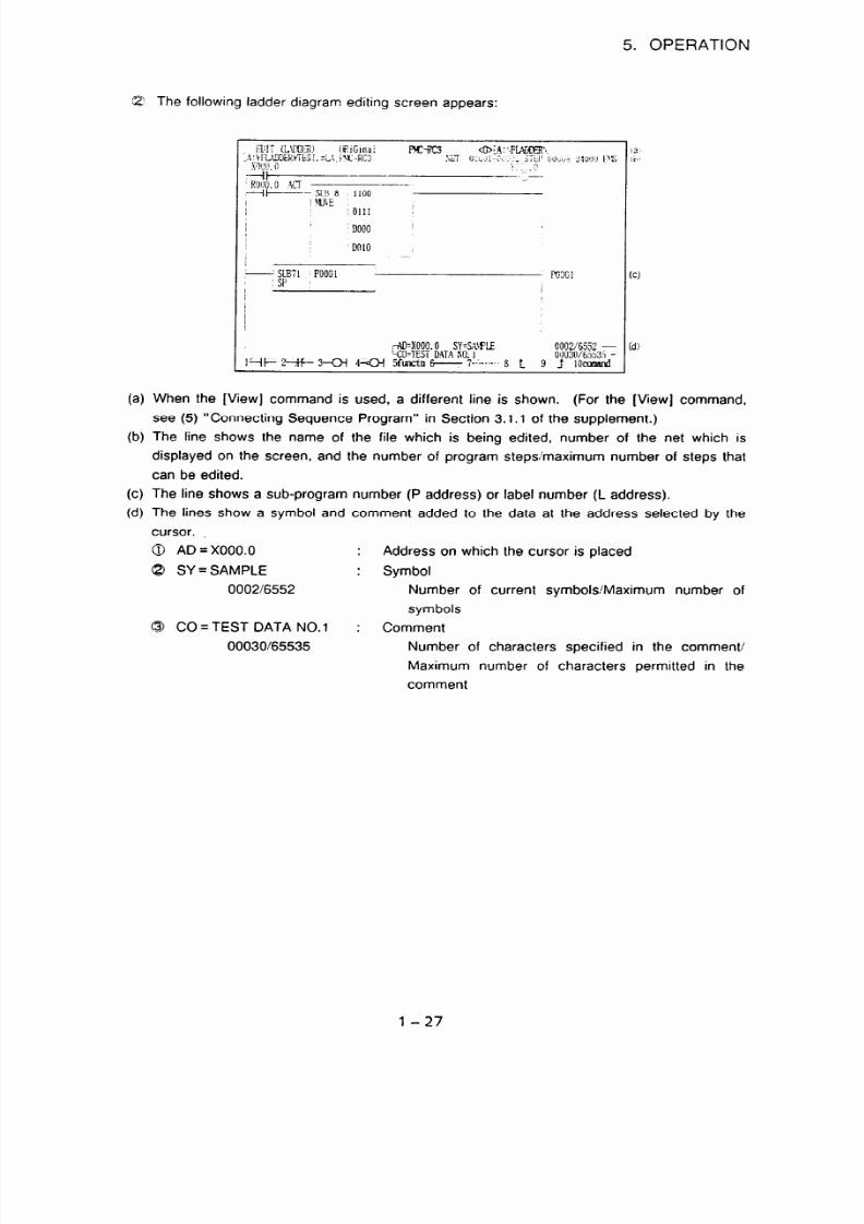
The following ladder diagram editing screen appears:
u StBl PO001
:sp
l-AD=xooo.
QTEST
0
SY=S:rFE 00026552 -
DATA NO I 0110306553S -
H- z+F- 3-a 4+3 %ztn + c--,-.. 6 t 9 _t 1ocuBm
When the [View] command is used, a different line is shown. (For the [View] command,
see (5) “Connecting Sequence Program” in Section 3.1.1 of the supplement.)
The line shows the name of the file which is being edited, number of the net which is
displayed on the screen, and the number of program steps’maximum number of steps that
can be edited.
The line shows a sub-program number (P address) or label number (L address).
The lines show a symbol and comment added to the data at the address selected by the
cursor.
@ AD = X000.0
: Address on which the cursor is placed
8 SY = SAMPLE
: Symbol
000216552 Number of current symbols Maximum number of
symbols
@ CO = TEST DATA NO.1
: Comment
0003Of65535 Number of characters specified in the comment/
Maximum number of characters permitted in the
comment
1-27

7/25/2019 FAPT Ladder for PC-Operator Manual
http://slidepdf.com/reader/full/fapt-ladder-for-pc-operator-manual 35/302
5. OPERATION
(2) Function key indications
and selection
The ladder diagram editing
functions correspond to the function keys as indicated below.
“-@
[coman_d]
Q Under condition CD),holding down [SHIFT] lets you select the following items.
r
::.>,:.:.,.:c.::~:~;:i:.:jl
::,:..:,:.:.\.:.:.:,:,: ... I. ..,
.:g:.:;er:.,_:~:::~i,~.~:1:I:I.~::1:1:::1:~.:81’:~~~.~:~~:~::.:,: .v.w ,l:...
. .:.:,:,~.:.:.:,:.:.:,::.:
:::::.i’:.:...:.:.:.:,~:.:.:.:.:.:.
;::,::,::::: :.:...:.
, ~~~~~~~ 2 ;,$; &k&; 3 ~~~~~~~~~~~~~~~~~~:~~~~~~~~~:;~~~~~~~~~~~~~~ 6 :~:~~~~~~~~~~~~~~~~~~~~~~~~~~~“~:~~:~~~~~~~~~,~~~~~~~~~~~:~~~~Oii,i’~::i:;~~~I~:::::ii
>::.:_:...:.:.::.__,...):.:_:.:.‘.l.,. >: . ._.... .y.._ ..\.,.:.:.:.:s...I :,
:..:.:
,.:..:.:.:.:_..::: .:,~):.:.:,‘..,, ,:.:Q..:.)
.i:: ,.,.,.,.,.,,,_,., .~)~);:_:_:.):.:‘:.:.::.~.,..:.:,.,.i,.,.,__.
@ [Delnet]
@ [Search]
. . ,. . : ,. .. . .., .,. ,.
. . ::..:.:...:..: . ..:,_,).)::
::,.,:.‘. ,,., ,
5 ;;,;;w&& 6 ;,&&i; ““‘: :i$&“.~. 8 ;. .,~&~:~~.Y: ‘_.,:_‘,:‘:l:;,~.;i’:i0,:: ;&.;;;:;I..
:.:’ ., : .C,‘.‘:’ ,.,.,:,..: :
..“.
CB
[Copy1
1
Wove1
I
$$&;:;.;
2
:l~a;~&;:
3 :
.karch ..I
4 ‘i_down 5 .t;“p,.,
6 ,.,
7.;, . . . . . . . ‘3.
,A
”
:.,,:,:: Y.
8
” .” ’
.:. ..I’ :,. . .
. .x. ‘.
g .Y’ .: --<;.I’, . ::
. .
I
., :. .,<. y
:::;t+r
Lj:;::.tii:.:.::..?
.
*
:. 3 :~..~&~ch
: 4 ‘:&own
5
c-up
6
tO-fil
7.
to J.
8.
,:
g
.:
,,
:
: i.‘, 10 .:,
* [to-org) is displayed in the [File] command mode only. (Thus can be selected.)
@I [File]
Opens a window in which the name of an input program can be specified. Select desired
processing from a POP-UP menu.
9 [
sy
Edit]
I
0xec 2
cancel
3
4
5
6
7
8 9
10
I
1-28

7/25/2019 FAPT Ladder for PC-Operator Manual
http://slidepdf.com/reader/full/fapt-ladder-for-pc-operator-manual 36/302
5. OPERATION
(3)
(Note)
While the function keys of @ are displayed in ladder diagram editing, a command of
Q can be executed. For example, entering <A > and [COMAND] on the @ screen
has the same effect as selecting F4 [Adress] on the .a screen. To select a
command of 8 in this way, enter the upper-case letter (not necessarily initial letter)
in the corresponding command name shown on the 8 screen.
Sequence program input
For sequence program input, select [LADDER] from the editing menu. The function key
programmer menu is displayed. When no sequence program has been entered, the screen
displays only the right and left vertical rails of a ladder diagram.
At this stage, program input can be started.
Use the cursor keys to move the cursor to any location in the ladder diagram.
Examples of basic instruction program input and function instruction program input are shown
below.
(a)
Example
of basic instruction program input
I
x0.1
D30.2 F14.2 Y52.7
3
[Operation ]
Move the cursor to the start position, then press [ -I I- 1.
The [ -I I- ] symbol appears on the screen. The message “HORIZONTAL LINE
ILLEGAL” appears at the lower-right corner of the screen. This message warns the
user that horizontal ladder diagram line creation is not completed. Enter an address
and bit data.
Enter X0.1 on the keyboard and press the < RETURN > key. The address is set at
the contact, and the cursor moves right.
As in @ and 8, enter contact A of 030.2.
Enter contact B of F14.2.
Press [ e ] and enter address F14.2. then press the <RETURN> key. The
address is set on contact B and the cursor moves right.
Without moving the cursor, press [ 4 1.
A horizontal line segment extending to the right is drawn automatically and a relay coil
symbol appears near the right vertical rail.
l-29
7/25/2019 FAPT Ladder for PC-Operator Manual
http://slidepdf.com/reader/full/fapt-ladder-for-pc-operator-manual 37/302
5. OPERATION
(b)
Example of function instruction program input
Enter address Y52.7. then press the <RETURN > key.
The cursor automatically moves to the input start position on the next line.
Next, enter an OR condition.
Press [ + ] and enter address X2.4, then press the <RETURN > key.
The address is set at contact 6 and the cursor moves right.
Press [ - ] to enter a horizontal line.
To enter a horizontal line, enter a number and press the horizontal line key
[
- 1. The line segment will be entered as many times as the number entered.
Note, however, that such a line never exceeds the right vertical rail.
A vertical line extending upward is required for OR. Press [ d ] to enter a
vertical line extending upward.
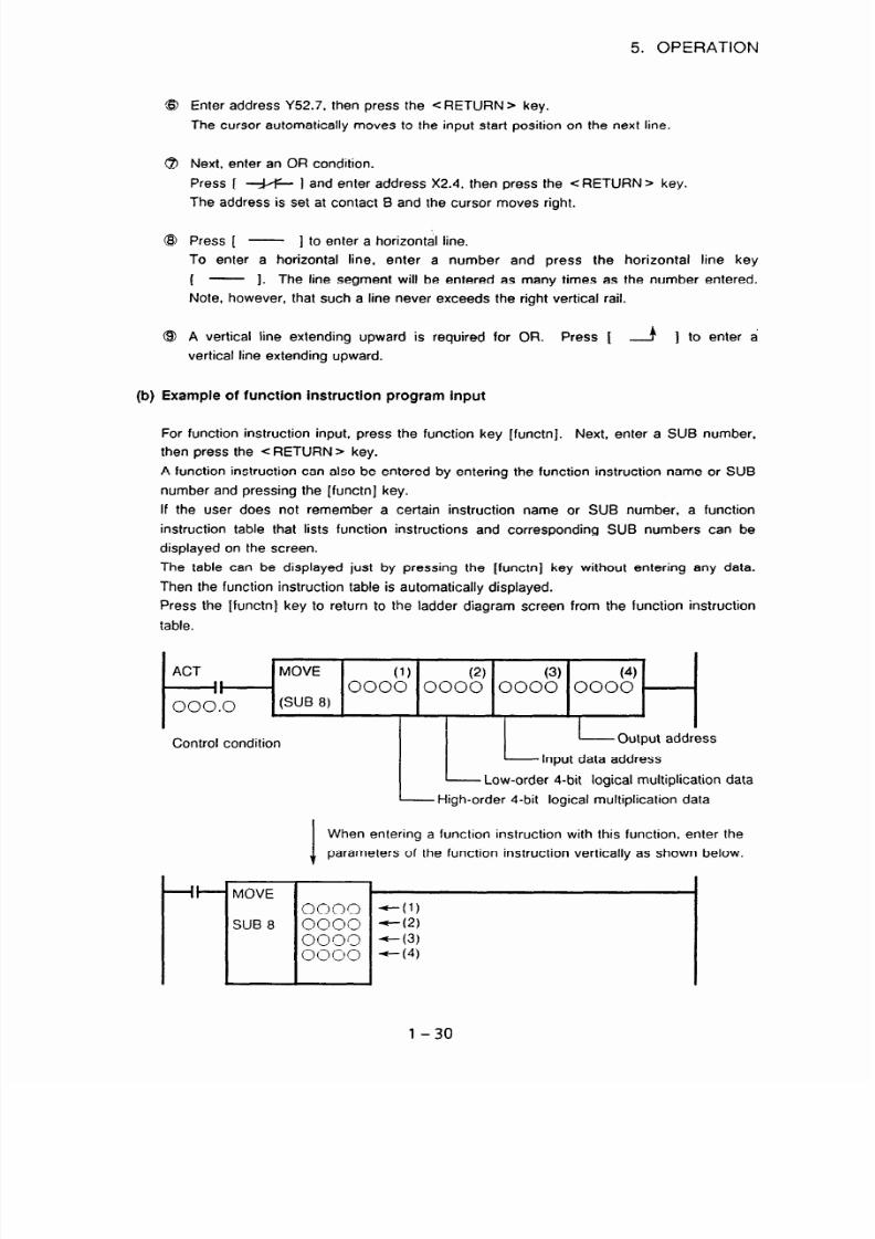
For function instruction input, press the function key [functnj. Next, enter a SUB number,
then press the <RETURN> key.
A function instruction can also be entered by entering the function instruction name or SUB
number and pressing the [functn] key.
If the user does not remember a certain instruction name or SUB number, a function
instruction table that lists function instructions and corresponding SUB numbers can be
displayed on the screen.
The table can be displayed just by pressing the [functn] key without entering any data.
Then the function instruction table is automatically displayed.
Press the [functn] key to return to the ladder diagram screen from the function instruction
table.
ACT
1 MOVE
Control condition
-It-- MOVE
SUB 8
.
I
(1)
(2)
I
(3) (4)
0000 0000 0000 0000
H
LL
- Output address
Input data address
Low-order 4-bit logical multiplication data
High-order 4-bit logical multiplication data
When entering a function instruction with this function, enter the
parameters of the function instruction vertically as shown below.
0000 -c-(l)
0000 --(,a
0000 -(3)
0000
-(4)
l-30

7/25/2019 FAPT Ladder for PC-Operator Manual
http://slidepdf.com/reader/full/fapt-ladder-for-pc-operator-manual 38/302
5. OPERATION
[Operation]
@ Enter a control condition.
Press [ -i t- 1. Next, enter an address and bit data, then press the <RETURN>
key. The cursor moves right.
Q Enter a function instruction.
Press the [functn] key. Next, enter SUB number 8, then press the <RETURN > key.
The function instruction diagram shown above appears.
& Enter the oarameters of the function instruction.
First, enter the high-order 4-bit logical multiplication data of the first parameter, then
press the <RETURN > key. The cursor automatically moves downwards. Enter the
remaining three parameters one by one.
(c) Restrictions and notes on ladder creation
[Restrictions]
@ Restrictions related to the ladder 1 net (corresponding to the portion between the RD
and WRT instructions)
a) When the ladder 1 net exceeds 256 steps (as counted as steps in the
corresponding mnemonic program), the following message appears:
“A limit of 256 steps per net was exceeded.”
If there are more than 256 steps, no net is displayed.
@ Restrictions related to a ladder diagram display per screen
If an attempt is made to display more than 70 ladder net lines per screen, the error
described below occurs.
a) Symptom
(a-l) When there are more than 70 lines per net, the following message appears.
“The NET being created is too large.”
If 70 lines are exceeded, the following message appears, and no net is
displayed.
“A limit of 70 lines per net was exceeded.”
(a-2) When there are more than 70 lines totaled over two or more nets, the following
message appears.
“The NET being created is too large.”
If 70 lines are exceeded when totaled over two or more nets, the following
message appears for a net that is the current net when 70 lines are exceeded,
and the display of the current net is discontinued.
“The NET is larger than the editing buffer.”
In this case, specify the net to be displayed. rrsing the ladder diagram search
function (such as net number search).
b) How to obtain the number of lines per screen
Even if part of a net is displayed on a screen, all lines of the net are included in the
l-31

7/25/2019 FAPT Ladder for PC-Operator Manual
http://slidepdf.com/reader/full/fapt-ladder-for-pc-operator-manual 39/302
5. OPERATION
total for that screen. In addition, a space line between nets is counted as a valid line.
The number of lines in each net to be displayed is determined as follows:
(b-l) Basic instructions
One line is comprised of one basic instruction.
b-1- 1 line
L-I *lines
(b-2) Function instructions
The number of lines in a function instruction is: The number of control conditions
or parameters, whichever is greater, plus 1
Examples of calculation follow.
- When the number of control conditions < number of parameters
RST
r
umber of control conditions = 2
Number of parameters = 4
Number of lines = number of
parameters + 1 = 5 lines
- When the number of control conditions > number of parameters
RlOO
Number of control conditions = 3
Number of parameters = 1
Number of lines
= number of control
conditions + 1 = 4 lines
1-32

7/25/2019 FAPT Ladder for PC-Operator Manual
http://slidepdf.com/reader/full/fapt-ladder-for-pc-operator-manual 40/302
5. OPERATION
(b-3)
Data table section of function instructions
The data table section of the COD, CODB, or DISP instruction is calculated as
follows:
When the data table is one or two bytes
Number of lines = number of data tables16 ( + 1 if there is a remainder)
0000
0000
0000
0000
0000 0000
Number of lines in the data table
0000 0000 section = 11/6
0000
0000
0000
1
= 1 with remainder 5
= 2 lines
I
When the data table is four bytes
Number of lines = number of data tables/4 ( + 1 if there is a remainder)
SUB 27 0005
CODB
0007
0300
D320
00000000
00000000
00000000
00000000
00000000
1
umber of lines in the data table
section = 514
= 1 with remainder 1
= 2 lines
l-33

7/25/2019 FAPT Ladder for PC-Operator Manual
http://slidepdf.com/reader/full/fapt-ladder-for-pc-operator-manual 41/302
5. OPERATION
(b-4)
Example of calculating the number of lines per screen
For the ladder shown below, the number of fines in the screen display section is
obtained as follows:
- The valid nets on the display screen are nets A and B.
- Number of lines in net A
Function instruction section + data table section = 6 lines
-I-+
8 lines
(3+1)
(1116)
I
- The number of lines in net B is 2.
ACT
Net A
r
-
Screen display section
. . . .
Net B
: . . . .
Net C
. . . . . . .
.
I
.
000
003
006
009
SUB 49
0011
DISP
0003
T
300
. . . . . . . . . . . . . . . .
0000 0000
0000 0000
0000 0000
0000 0000
. . . . . . . . . . .
0000
0000
0000
.
........
........
c) Examples of symptoms
Example of symptom (a-l)
-
The ladder diagram can be edited only when the “total number
parameter of the DISP instruction (SUB 49) is less than 396.
the total number of steps is 396, the net consists of 70 lines.
of message data steps”
This is because when
If a net that consists of a total of 396 steps or more is created during mnemonic
editing, the following message appears, and the display of the net is discontinued.
“The data table is too large.”
1-34

7/25/2019 FAPT Ladder for PC-Operator Manual
http://slidepdf.com/reader/full/fapt-ladder-for-pc-operator-manual 42/302
5. OPERATION
Example of symptom (a-2)
-
If an attempt is made to enter the net of a function instruction on the same screen as
that of a basic instruction, the following message is displayed, and the attempt is
rejected.
“The NET being created is too large.”
For example, if the basic instruction net has 68 lines, the MOVE instruction (SUB 8)
cannot be entered, (because the total number of lines exceeds 70). The results of
calculation are described below.
. t+r
isplay screen
. . . . . . . . . . . . . . . . . . . . . . . . . . . . . . . . . . . . . . . . .
1
: . . .
68-line net
Number of MOVE
i instruction lines =
i number of parameters
; (4) + 1 = 5
.. 68 + 5
= 73 lines
< Measure >
If the display of the 68-line net is not scrolled, the MOVE instruction can be entered.
_
A basic instruction net cannot be entered together with another basic-instruction net, if
the total number of lines is greater than 70.
For example, if a 68-line basic-instruction net is followed by another basic-instruction net,
the element of the third line of the latter net cannot be entered.
Display screen
I+‘+
,..................................................._.___.....,_...........................
I . . . . :: j .I...l
] 68-line net
< Measure >
If the display of the 68-line net is not scrolled. the latter basic instruction can be entered.
- When the CODB instruction (SUB 27) and DISP instruction (SUB 49) are edited on the
same screen, if an attempt is made to enter 396 as the total number of message data
steps for the DISP instruction (SUB 49) the following message appears, and the
l-35

7/25/2019 FAPT Ladder for PC-Operator Manual
http://slidepdf.com/reader/full/fapt-ladder-for-pc-operator-manual 43/302
5. OPERATION
attempt is rejected.
“The NET being created is too large.”
This symptom also occurs in a combination of two DISP instructions and a combination of
CODB and COD instructions.
For example, if the number of tables for the CODB instruction is 200, the total number of
steps for the DISP instruction can be only 66 at maximum. The calculation results are
shown below.
Display screen
. . . . . .
FIST
-II-
ACT
-II-
000
00000000
00000000
002 00000000 00000000
. . . . . . . . . . . . . . . . . . . . . . . . . . . . . .
196
00000000
00000000
198 00000000
00000000
. . . . . . . . . . . . . . . . . . . . . . . . . . . . . .
4 bytes
200 data tables
.
.
I[
. .
Number of CODB
_ instruction lines = 55
Function instruction
section
= 4 parameters
+ 1
Data table section
= 20014 = 50
I_
alculation of DISP
- instruction data items -
that can be entered
Function instruction
sections
= 3 parameters
+ 1
Number of remaining
lines
= 70 - 55 - 4
= 11 lines
Data tables
= 11%=66
< Measure >
Moving the DISP instruction to the top of the display screen makes it possible to set the
total number of steps to 396.
8 Restriction on the maximum number of steps
The maximum number of ladder steps that can be edited is as follows:
Without EMS : 21840 steps
With EMS : 24000 steps
Note, however, that the maximum allowable number of steps can decrease, depending
on how memory is used.
If a ladder being edited exceeds the maximum allowable number of steps, editing is
disabled and the following message is displayed:
MNEMONIC BUFFER OVER
l-36

7/25/2019 FAPT Ladder for PC-Operator Manual
http://slidepdf.com/reader/full/fapt-ladder-for-pc-operator-manual 44/302
5. OPERATION
(4)
(5)
[Notes]
CD An attempt to scroll a program on the screen with a scroll key or other keys fails if the
ladder program is incomplete (for example, without addresses) or invalid.
A correct ladder program must be created before the screen can be scrolled.
Q Up to eight contacts and one coil can be entered in one line on the screen.
However, this restriction does not apply to a sequence program created in mnemonic
format. When a sequence program created in mnemonic format exceeds this limit, it is
displayed over several lines with a continuation symbol.
This continuation symbol cannot be deleted with [ ----- 1. Use [Delnet] (net
deletion) to delete this symbol. (See Item (6) in this section.)
Replacing sections of a sequence program
Lines in an already created sequence program can be replaced
in Item (3) above.
in the same way as described
Move the cursor to a program section to be changed, then enter
new data.
Sequence program addition
Press the [comand] soft key of the function key programmer menu and use the function keys
indicated below.
To terminate the programmer menu, press the < ESC > key.
I
I,
&&t’
.......................
:
.................:......................................
.. .... .... ...
..
.... :.
~::::&I&:1 > &if:‘$::
:zi~~~~~~::
~$z$,$@:i;i
.
.................
: :..:.q.::::. :;. ‘,,::::
:,: : :.:.:.:
. . : :::‘.:+~:.~~x~
: .: ,y,:: ... . . :, . ..... .:‘:::I
... ................
.:::.y
$&&$ ~~~;fjiii.~~~
$zzyrdit:::;,
.................:.:.:::::::::::::: ........y.. .........
,.:’ :: ,.:,:: ... .::..: .: .... .:::::.:.:.
........
... : : ::.:. .:::.:
[Insert]
As described below, there are four types of sequence program addition in a ladder diagram.
(a) Example: when a relay contact is added on a line
Addition on a line
Move the cursor to the position to add item(s), then enter item(s) in the way described in
Item (3) above.
l-37
7/25/2019 FAPT Ladder for PC-Operator Manual
http://slidepdf.com/reader/full/fapt-ladder-for-pc-operator-manual 45/302
5. OPERATION
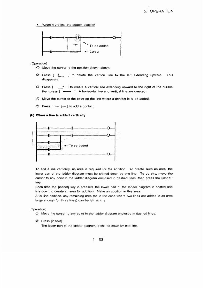
When a vertical line affects addition
[Operation]
Move the cursor to the position shown above.
Press [
4
] to delete the vertical line to the left extending upward. This
disappears.
Press [
A ] to create a vertical line extending upward to the right of the cursor,
then press [ -
). A horizontal line and vertical line are created.
Move the cursor to the point on the line where a contact is to be added.
Press [ -j j- ] to add a contact.
(b) When a line is added vertically
-To be added
To add a line vertically. an area
lower part of the ladder diagram
cursor to any point in the ladder
key.
is required for the addition. To create
such an area, the
must be shifted down by one line. To
do this, move the
diagram enclosed in dashed lines, then
press the [insnet]
Each time the [insnet] key is pressed, the lower part of the ladder diagram is shifted one
line down to create an area for addition. Make an addition in this area.
After line addition, any remaining area (as in the case where two lines are added in an area
large enough for three lines) can be left as it is.
[Operation]
@ Move the cursor to any point in the ladder dragram enclosed in dashed lines.
G? Press [insnet].
The lower part of the ladder diagram is shifted down by one line.
l-38

7/25/2019 FAPT Ladder for PC-Operator Manual
http://slidepdf.com/reader/full/fapt-ladder-for-pc-operator-manual 46/302
5. OPERATION
When the [insnet] key is pressed without entering a numeric value, one line is inserted.
When the [insnet] key is pressed after entering a numeric value, the number of
specified is inserted.
Move the cursor to the desired position and press [ -_( l-j. Then set address
and press the <RETURN > key. The the cursor moves right.
Press the [ L ] soft key to create an OR circuit.
lines
data
(c) Line insertion in a single-net sequence program
Blank lines are inserted one by one.
[Operation)
0 Enter the number of lines to be inserted, then press the [insfin] key. The entered
number of lines is inserted.
(When the [inslin] key is pressed without entering a number, just one line is added.)
If the [inslin] key is pressed when the cursor is positioned as shown in the left-hand
figure. a blank line is inserted as shown in the right-hand figure.
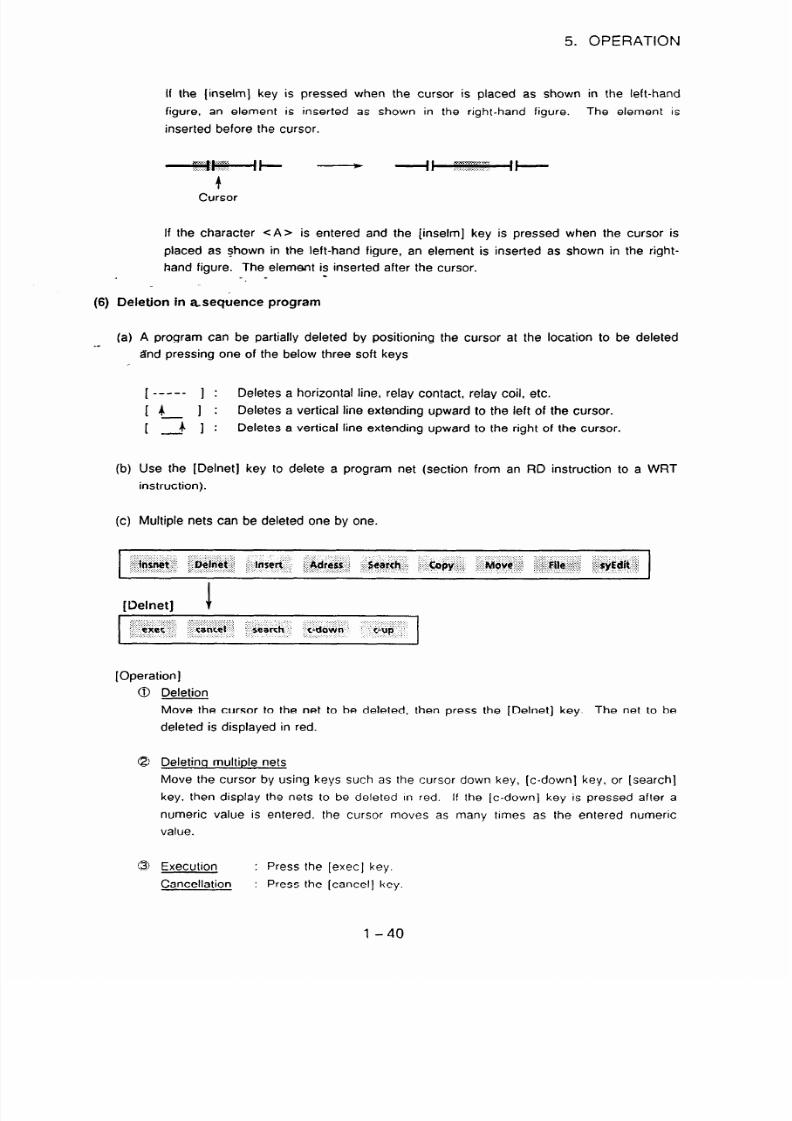
(d) Element insertion
in a single-net sequence program
Elements are added one by one.
[Operation]
0 Enter the number of elements to be inserted, then press the [inselm] key. The entered
number of elements is inserted.
If the character <A> is prefixed to the number of elements to be inserted and the
[inselm] key is pressed. elements are inserted after the cursor.
(If the [inselm] key is pressed without entering the number of elements to be inserted,
just one element is inserted.)
_‘~&$+ -
, <c..mm I I
II
n.. :.>:.....:.>:... (
I
4
Cursor
1-39
7/25/2019 FAPT Ladder for PC-Operator Manual
http://slidepdf.com/reader/full/fapt-ladder-for-pc-operator-manual 47/302
5. OPERATION
If the (inselm] key is pressed when the cursor is placed as shown in the left-hand
figure, an element is inserted as shown in the right-hand figure. The element is
inserted before the cursor.
If the character <A> is entered and the [inselm] key is pressed when the cursor is
placed as Shown in the left-hand figure, an element is inserted as shown in the right-
hand figure. The element is inserted after the cursor.
-_ -
(6)
Deletion in asequence program
(a) A program can be partially deleted by positioning the cursor at the location to be deleted
-_
&td pressing one of the below three soft keys
[
e__--
1 :
Deletes a horizontal line, relay contact, relay coil, etc.
[4
I:
Deletes a vertical line extending upward to the left of the cursor.
1
2 ] :
Deletes a vertical line extending upward to the right of the cursor.
(b) Use the [Delnet] key to delete a program net (section from an RD instruction to a WRT
instruction).
(c) Multiple nets can
be
deleted one by one.
[Delnet]
1
[Operation]
Deletion
Move the cursor to the net to be deleted, then press the [Delnet] key. The net to be
deleted is displayed in red.
Deleting multiple nets
Move the cursor by using keys such as the cursor down key, [c-down] key, or [search]
key, then display the nets to be deleted In red.
If
the [c-down] key is pressed after a
numeric value is entered. the cursor moves as many times as the entered numeric
value.
Execution : Press the [exec] key.
Cancellation : Press the [cancel] key.
l-40

7/25/2019 FAPT Ladder for PC-Operator Manual
http://slidepdf.com/reader/full/fapt-ladder-for-pc-operator-manual 48/302
5. OPERATION
@ When the nets to be deleted are known beforehand, move the cursor to the first net to
delete, enter the number of nets to delete. then press the [Delnet] key. With this
operation, steps G and 8 can be omitted.
(7)
Searching in a sequence program
A sequence program can be searched using the following soft keys:
(Search1
1
When this key is pressed, the start of the sequence
and the cursor is moved to the start of the program.
(b) [bottom]
program is displayed on the screen
When this key is pressed, the end of the sequence program is displayed on the screen and
the cursor is moved to the end of the program.
(c) [srchl
Search operation using this key searches the program for aspecified address from the
current location for the cursor on the screen to the end of the program. When an address
is found, it is displayed on the screen. An address to search for can be specified in one of
two ways.
0 Address specification usina the cursor
Move the cursor to the relay contact of the address to search for, then press the [srch]
key. This operation searches the program for the specified address from the current
location of the cursor on the screen to the end of the program.
If the specified address is found, the section of the program containg the address is
displayed on the screen. The cursor is automatically positioned at the found address.
If the search operation fails to find the specified address, the cursor does not move.
To terminate searching, press the c ESC > key.
l-41
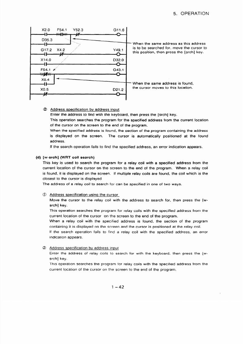
7/25/2019 FAPT Ladder for PC-Operator Manual
http://slidepdf.com/reader/full/fapt-ladder-for-pc-operator-manual 49/302
5. OPERATION
Gll.6
-- When the same address as this address
Y49.1
is to be searched for. move the cursor to
this position, then press the (srch] key.
D32.0
Address soecification bv address inout
Enter the address to find with the keyboard, then press the [srch] key.
This operation searches the program for the specified address from the current location
of the cursor on the screen to the end of the program.
When the specified address is found, the section of the program containing the address
is displayed on the screen. The cursor is automatically positioned at the found
address.
If the search operation fails to find the specified address, an error indication appears.
04
(w-srch] (WRT coil search)
II
F54.1 ,.“’
x0.4 -
II .
II
x0.5
GE.1
021.2
When the same address is found,
the cursor moves to this location.
This key is used to search the program for a relay coil with a specified address from the
current location of the cursor on the screen to the end of the program. When a relay coil
is found. it is displayed on the screen.
If multiple relay coils are found, the coil which is the
closest to the cursor is displayed
The address of a relay coil to search for can be specified in one of two ways.
@ Address soecification usino the cursor
Move the cursor to the relay coil with the address to search for, then press the [w-
srch] key.
This operation searches the program for relay coils with the specified address from the
current location of the cursor on the screen to the end of the program.
When a relay coil with the specified address is found, the section of the program
containing it is displayed on the screen and the cursor is positioned at the relay coil.
If the search operation fails to find a relay coil with the specified address, an error
indication appears.
@ Address specification bv address inout
Enter the address of relay coils to search for with the keyboard, then press the (w-
srch] key.
This operation searches the program for relay coils with the specified address from the
current location of the cursor on the screen to the end of the program.
l-42

7/25/2019 FAPT Ladder for PC-Operator Manual
http://slidepdf.com/reader/full/fapt-ladder-for-pc-operator-manual 50/302
5. OPERATION
When a relay coil with the specified address is found, the section of the program
containing it is displayed on the screen and the cursor is positioned at the relay coil.
If the search operation fails to find a relay coil with the specified address, an error
indication appears.
(e) [n-srch] (net-number search)
This key displays those ladders that have a specified net number, starting from the top of
the screen. If the [n-srch] key is pressed without entering a number, the display is
advanced by one net.
(f)
[s-srch
]
(function-instruction search)
This key searches for function instructions. Searching is performed by entering a function
instruction name or number, then pressing the [s-srch] key. If the [s-srch] key is pressed
while the cursor is on a function instruction, function instructions with the same number as
that function instruction are searched for.
(g) Search operation using the cursor keys
(< c >, -z + >)
Enter an address or symbol, then press a cursor key. The address is searched for.
Enter a NET No., then press a cursor key. The NET No. is searched for.
Enter a function instruction name, or enter S followed by a function instruction number,
then press a cursor key. The function instruction is searched for.
Example: Enter Sl, then press a cursor key.
The function instruction END1 is
searched for,
(h) Searching in all main/sub-programs(G-SRCH)
When the source program type is
“FORMAT-B/C”, global searching in all main/sub-
programs is enabled.
Refer to “APPENDIX 6 Managing a Source Program” for source program type.
1) The range of search
All programs, which include a currently displayed subprogram, are searched for.
The subprogram is searched for in the ascending order of P address.
a) From the current cursor position to bottom of currently opening subprogram.
b) From next numbered subprogram to last numbered one.
c) From LEVEL1 to subprogram of which P address is small next to a).
d) From top to cursor position in subprogram of a).
l-43

7/25/2019 FAPT Ladder for PC-Operator Manual
http://slidepdf.com/reader/full/fapt-ladder-for-pc-operator-manual 51/302
5. OPERATION
G-SRCH mode continues unless pushing the < ESC > key or the [cancel] key.
__1.
A
1st net of LEVEL1
8
I@
@
@
m t cursor
t displaying on
one of
the screen
Whole
@
1
subprograms
program
0
@
Th
Final net of the maximum numbered subprogram
v
(Searching in the order of @ -@I)
a
Searching result
When the object of search is found, the cursor will move to the position.
In case of finding in another program the program which is currently displayed will be
closed.
Then, the program which contains the object, will be opened to display the object
position with the cursor.
At this time, whether to save or quit modifications is inquired, in case there are
modifications in the program to be closed.
When two or more objects exist, the result of search are displayed in order of 1) one
by one.
l-44

7/25/2019 FAPT Ladder for PC-Operator Manual
http://slidepdf.com/reader/full/fapt-ladder-for-pc-operator-manual 52/302
5. OPERATION
3) Operation
The global search is operated with the following function key.
0
8 [comand]
(comand]
J
@ Select the [G-srch] with pushing the [SHIFT] (the following will be displayed) in state of 8
[G-SRCH] 1
(Shortcut command is ” <G > +
[COMMAND]“)
a)
Beginning of “G-SRCH” mode
It switches to the mode of “G-SRCH” by the operation of 0 + 9.
After that, all programs are searched unless quitting “G-SRCH” mode.
b)
Execution of search
Refer to “(c) [search]“,“‘(d) [w-srchj”Y(e) [s-srch]” in “(7)Searching in a sequence
program”, for how to specify the target of global search.
c)
End of “G-SRCH” mode
“G-SRCH” mode is ended by pushing < ESC > or [CANCEL] key. The end method is
different individually.
- <ESC> = Only “G-SRCH” mode is ended. The program on the opening now
is the state as it is.
- [CANCEL] = It returns to the program which was opened at beginning the “G-
SRCH” mode. The program on the opening now closes.
Whether will save or quit modifications is inquired, in case there are
modifications in the program which IS currently displayed.
Copying sections of
a
sequence program
A multiple-net sequence program can be copied net by net. Specify the net to be copied. The
net can be copied in the same file that IS being edited or Into another file. The selected net
remains as it was.
l - 45

7/25/2019 FAPT Ladder for PC-Operator Manual
http://slidepdf.com/reader/full/fapt-ladder-for-pc-operator-manual 53/302
5. OPERATiON
File which is beinq edited
[COPY
1
Range to be copied
[until]
Fig. 51.2 (6)
Specified file
[COPY]
I
.,:/..:...\:::..:...;....,’ :,
.‘.Z’_’ ,” . ..‘).’ .:.:.::,:.:.‘.:.‘:.:.:,:.;,, ..:.:.:...:.:.:.::.‘...:.:.:.:.L:.,.
:.:.:.:.:.:.:,‘.‘:y(.:.~.:::
:.:.:i’i .:,:,y .
:.>;.x ,:.y
.‘.....‘.:.:Q:.:.:~:.:.~.:.: 1:.
$$
::;$$,j:$;~:
++t :I;,
$ S;+b ;; ;:&J&&,l ~~i~~~~~~,~~~:~~pI~~, j@$j$$
:: ::..:.:- ,. .:::::::::
$+.:. .:.:.:.:i.::,.:::::::: .,:.:..::::: .~:::.:.:.~.:::.:.;::..‘_,._. .:
I
[Operation]
Copying a net
Place the cursor on the net to be copied and press the [Copy] key. The selected net is
displayed in yellow.
Copying two or more nets
To select the nets to be copied, first move the cursor to the first net of the range to be
copied, then move the cursor to the net at the other end of the range to be copied by
pressing the cursor up, cursor down, [c-up], [c-down], or [search] key. The selected nets
are displayed in yellow.
Alternatively, enter a numeric value and press the [c-up] or [c-down] key. The cursor
moves according to the specified value.
Setting the net or nets to be copied
Press the [until] key.
Specifying the copy destination using the
file)
[to] key (Copying the net or nets in the same
Move the cursor to the copy destination in the same file and press the (to] key. The
l-46

7/25/2019 FAPT Ladder for PC-Operator Manual
http://slidepdf.com/reader/full/fapt-ladder-for-pc-operator-manual 54/302
c3
-
*
@
5. OPERATION
selected net or nets are copied immediatelv above the CODY destination specified by the
cursor.
To copy the selected net or nets two or more times, enter the number
of times
they are to be copied before pressing the [to] key.
Specifying the copy destination using the [to-fill key (Copying the net or nets into another
file)
1)
2)
3)
4)
Press the [to-fit] key. The following message is displayed.
If no program is specified, LATMP is created.
c,
i:~l::::::~~:l::t’:l:::ill:~:~~:~:~:~:~.’ . :.:
.‘:::::::::,:,,:. .:. .$,,
ix::::
,.,.
~:~~.:.:.:.:.:c.:.:.:.::~~~~:~:~:~:~~~::ii:
: ::;.:~
‘;:?:(“.‘.”
::
:
. .:...:...:.:.:.)):::.:~l:~‘.~:..:‘.~.‘:,,,...,:.
: : :,: .y :
. ... .
.
(LATMP file: Provisional work file used in editing)
Enter the-name of the file into which the net(s) is to be copied and press the
<RETURN > key.
Select desired processing from the following POP-UP menu:
/I
If the selected destination file is present, the following POP-UP menu is displayed.
Select desired processing from the menu.
The file already exists.
~1
Update
F2 Quit
F Append
Updates the selected file. The new copy replaces the
previous data of the file.
Cancels output to the selected file.
Appends the copy to the selected file.
If the nets to be copied are known beforehand, place the cursor on the first net to be
copied, enter the number of nets to be copied, then press the [Copy] key. Steps @, ai,
and @ can be skipped.
(Note) Incorrect nets cannot be copied.
(9) Moving sections of a sequence program
A multiple-net sequence program can be moved net by net. Specify the net or nets to be
copied. The selected net or nets can be moved to another place in the same file that is being
edited or output to another file. The selected net or nets are deleted.
The only difference between copying and moving is that the selected net or nets are deleted in
moving.
-tIWlet Delnet Insert Adress
Search
WY
Move File syEdit
[Move]
until
cancel search
c-down c-up
to
cancel search
c-down
C-UP
to-fil
+org
l-47

7/25/2019 FAPT Ladder for PC-Operator Manual
http://slidepdf.com/reader/full/fapt-ladder-for-pc-operator-manual 55/302
5. OPERATION
[Operation]
Substituting [Move] for [Copy], follow steps 0 to $3 for copying.
(Note)
incorrect nets cannot be moved.
(10) Combining a sequence program
A source program can be combined to another source program that is being edited.
The source program to be combined can be displayed and edited separately, then combined to
the original source program that is being edited.
[}-9
Section to be edited
Original screen
File being edited
(original file)
t
View screen
r
I
F-01
Combine
1
dit
Edited file to be
combined
Fig. 51.2 (7) Combining a Sequence Program
The model specified for the FAPT LADDER system must agree with the PMC model of the file
to be entered on the original screen.
However, the file to be combined can be specified for
(TO) or entered for (VIEW) even if the two models do not agree with each other. (If a
disagreement is found, a warning message is displayed.)
In this case, no errors will be detected even if the file to be combined contains an address
range or function instruction format that does not agree with the specified model. (The error
will be detected in compilation.)
When ignoring the warning message to continue the
operation, extreme care is needed.
l-48

7/25/2019 FAPT Ladder for PC-Operator Manual
http://slidepdf.com/reader/full/fapt-ladder-for-pc-operator-manual 56/302
5. OPERATION
1) Function keys
[Comand ]
” ::. ” :.
..‘.. .
: .
&
. .
inmet
~ BPiiiei:’ I_lnreti. : :“Adiers
Se&&. j r &,fjjf ;:;:: ;,.:&qove..
syEdii
ORIGINAL = display when the file is opened for the first time
View
= display when the file is opened using the [File] command
PMC Model on which editing is carried out on the View 1 screen
- ORCSAL = Intia dspa) at openng the file
=Dspay opened by [Fle comand
-- Mode o PMC edted in Vew screen
EDT .~LAN Eii: VlCW
A YFLADDERFTEST :LA PYCfiC3
; x0000
+;
+ SiB71 I PO@@
ISP I
Kmmm
NET 0000100002 STE
YOOO 0
”
sY=AwE 00026552 1
I
Fig. 51.2 (8)
Screen Displayed
when a
File is Opened
by the (File] Command
l - 49

7/25/2019 FAPT Ladder for PC-Operator Manual
http://slidepdf.com/reader/full/fapt-ladder-for-pc-operator-manual 57/302
5. OPERATION
2)
Operation flowchart for combining a sequence program
Specify an insertion point (The
data is inserted immediately
above the cursor.)
I
[ Press thl:LE] key 1
) Specify ; view file 1
c POP-UP menu >
4 (View)
+ (To)
Combines the file with
the Ladder program on
the original screen
Shows the ladder
diagram of the file to be
combined (View screen)
1.
2.
Check the displayed
data of the file to be
combined
Edit the data of the
file to be combined
and combine it
Edit the Ladder program
on the view screen
(Normal editing)
I
ress the c ESC > key to terminate editing
1. The file is
immediately
combined.
The
data of the file is
not displayed.
< POP-UP menu s
+
(Save)
Saves the Ladder
program shown on the
view screen
$ (Edit)
Returns to the ladder
diagram screen (The
view screen is
continued.)
* 1: The name of the provisional work file is LATMP.
Fig. 51.2 (9) Operation Flowchart for Combining a Sequence Program
1 - 50

7/25/2019 FAPT Ladder for PC-Operator Manual
http://slidepdf.com/reader/full/fapt-ladder-for-pc-operator-manual 58/302
5. OPERATION
3) Examples
Example 1. Combining a sequence program file
[Operation]
Place the cursor on the insertion point on the original screen.
Select [File].
Enter the name of the file to be combined and press the <RETURN > key.
From the following menu, select Fl (To).
The file is inserted immediately above the net specified in step 0. (Original
screen)
Example 2. Combining a modified sequence program
[Operation]
Place the cursor on the insertion point on the original screen.
Select [File].
Enter the name of the file to be combining and press the <RETURN > key.
From the following menu, select F2 (View).
Edit the Ladder program on the view screen.
To terminate editing, press the
<ESC> key.
(Ladder editing can be performed and terminated in the
conventional way.)
l-51

7/25/2019 FAPT Ladder for PC-Operator Manual
http://slidepdf.com/reader/full/fapt-ladder-for-pc-operator-manual 59/302
5. OPERATION
@I From the following menu, select Fl (Save).
Temp (Outputs the data to the LATMPm file.)
8 Return to the screen of step-@‘and check -the name of the file output in step @.
Then, select Fl (To).
Y
.- @I -The-file is inserted immediately above the net specified in step 0.
(Original
screen)
Example 3. Combining a specified section of a sequence program
[Operation]
Place the cursor on the insertion point on the original screen.
Select [File].
Enter the name of the file to be combined and press the <RETURN> key.
From the pop-up menu, select F2 (View).
Select [Copy] or [Move] on the view screen and specify a desired range with
(until].
From the following function menu, select [to-org]. (Specify insertion into the
original screen.)
[until]
to
cancel search c-down c-up
to-fil to-org
From the following menu, select Fl (Exec).
jj
The data is inserted immediately above the net specified in step 0. (Original
screen)
1-52

7/25/2019 FAPT Ladder for PC-Operator Manual
http://slidepdf.com/reader/full/fapt-ladder-for-pc-operator-manual 60/302
5. OPERATION
(11) Editing a symbol and comment from the ladder diagram editing screen
On the ladder diagram editing screen, a symbol and comment added at the specified address
can be edited.
[Comand]
[syEdit]
1
I
:,Y;~y~r”::~:~ .:
~~:;~::;:‘::::.,:,:j ::
:ig:::iexee+::
..I. .?. .A. . .
. .
,.,., .,.,. ,:
aiijans~l, j3
: . . . .
I
[Operation]
Specifying an address
To edit a symbol and comment in a ladder diagram, place the cursor on the corresponding
address and press the (syEdit] key.
Editing the symbol and comment
The cursor moves to the symbol editing section in the bottom right part of the screen. Edit
the symbol and press the <RETURN > key. The cursor moves to the comment field.
Terminating editing
(exec] key
: Terminates editing after modifying the data.
[cancel] key :
Terminates editing without modifying the data.
(12) Abbreviated input with the [cornand] key
Each function key can be directly selected with the [comand] key. Enter one of the character
strings below, then press the [comand] function key.
Those portions that are enclosed in
brackets can be omitted.
I (nsert) D (elnet)
SY)E NW
S (earth)
c (OPY)
M (ove)
F (ile)
The function keys in the menu above can be used for program creation and search operations.
(Note)
The keys [ k or L ] and [J orJ ] are used to create or delete a vertical line
extending upward to the left or right of the cursor in a ladder diagram. The solid vertical
line is for creation and the dashed vertical line IS for deletion. The menu item applying
to a function key depends on the ladder diagram and cursor position.
l-53

7/25/2019 FAPT Ladder for PC-Operator Manual
http://slidepdf.com/reader/full/fapt-ladder-for-pc-operator-manual 61/302
5. OPERATION
(13) ZOOM
When the source program type is “FORMAT-B”, it is realized with easy operation to refer and
edit another subprogram, which is called by the CALU CALLU instruction from the program
now on the opening.
For the source program type, refer to “APPENDIX 6 Management a source program”.
1)
2)
3)
Start up of zoom
a)
Moved the cursor to the parameter of the CALUCALLU instruction and push the
<RET> key.
b) The program now on opening hides from the editing screen. Then the subprogram
which is specified by the parameter in mentioning above appears on the screen.
Start up under editing
When ZOOM is attempted while editing the program, the preservation of modifications will
be inquired. Select either.
End
of ZOOM
Close the current program.
I
I
l Save 8 zoom
F2 Cancel
I
When the end operation with the =zESC > key is attempted in the program editing screen
by ZOOM, it will return to the state when ZOOM is started. Moreover, it is possible to
return to the program configuration screen all at once.
End menu of editing screen (pop-up screen)
Fl Save(update) & quit
F2 Quit
F3 Renamesave & quit
F4 Edit
F5 Main
a) Fl:Save(update) & quit
It returns to the program screen where ZOOM was started, after the content of current
program screen is preserved.
b) F2:Quit
It returns to the program screen where ZOOM was started, after the content of current
program screen is cancelled.
l-54

7/25/2019 FAPT Ladder for PC-Operator Manual
http://slidepdf.com/reader/full/fapt-ladder-for-pc-operator-manual 62/302
5. OPERATION
c) F3:Rename, save & quit
It returns to the program screen where ZOOM was started, after the content of current
program screen is preserved into specified subprogram name.
(14) List of subprograms in use
The list of subprograms called from currently displayed program is displayed.
For the function. refer to the., “chapter 12. Creating a st ep sequence (14) Li st"of "FAPT
LADDER (personal computer) supplementary operator’s manual B-66131/04-6”.
Only the operation is described here.
1) Operation
The command “List” is operated with the following function key.
0
[comand]
1
8 [comand]
............................................
......
,.,:.:.........
.......
: ..........
..:. I :,,,:y::‘.Ii:‘:
;.,,:<;;;:<.y
........... ....x,?
......... ........
.y,:+:)(,.,:.:. j. : : : ::IQi
1 $$$i&$;;$ 2 :‘~,~i5t~ 3 $$$&$:$j;j4 ‘.$&&&r$r_ij ;;&&&;i 6 $$;$$.tt$$
7 ~&~~~ 8 ~~>:,.$&$;~~$$;&gijllia@:ii o:~~:~~:.:~:~~~,d~~
...... : .:.
.....
..... ............... ... .. ..........
......
: ...... :
..........
.....
@ Select the [List] with pushing the [SHIFT] (the following will be displayed) in state of 8
I
. :. :.....;,. :,.:,./.
A.. . . . . . .I . . . . : .::,::.:.. . .
,.. . .
.,y,.:. :.:::,.
:
fZy... .. :.:.;:.:. :..,.
: ,....:.:.:.:..
’I’I:I:I:i:i’:
_‘,‘...‘........‘.,.~.~i.,~~, :...,.,.. . .:.,.:
1 : :::~::.~$~:,.,~~~~
i~~~~~~~~~i:aiiQqiiaiiiij:iii~~~~~~
:il~,id,iri;i3:,~:~ $$,e) $::i; 6 ‘:i:iil.::‘~;:i~~~~~~jxiiil~;~~~~: 8
~~~i~~~~riiiilli
~~;i::~iis::::iiiiOr;.;$, ift j,: ::l)j
..: :::,., ~,
,( :.>y.
.,
. : .: :. . :
. .\ . .:.::;
.L... )‘.
. . . . .
.::,:.:::.y::/~ :. :,:,: :::j
..I
(Shortcut command is ” < L > + [COMMAND]“)
(15) To edit Net comment
It is able to write the comments between ladder nets.
These comments are called “Net
comment”,
and each of them occupies two steps in sequence program.
1)
To enter Net comment
a)
Move the cursor to the position you want to write a net comment.
And then press ” <Shift > + [netcmt]“.
R1OO1. O R1000.2
Y2000. 4
n
R1OO1. O
R1000. 2
Y23. 4
+*I
A
l-55
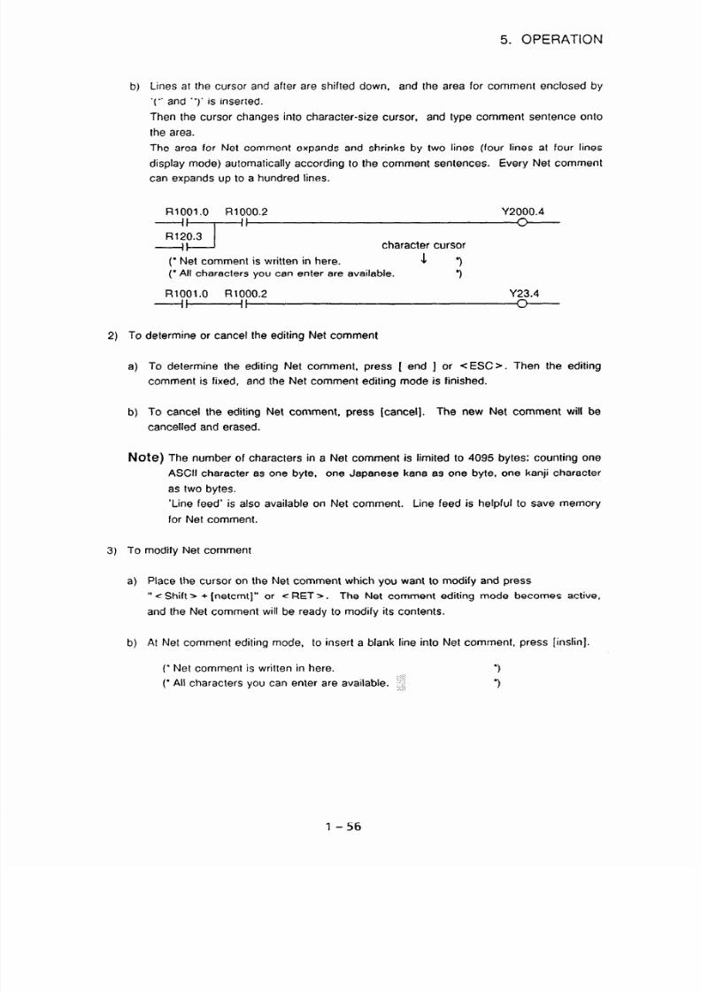
7/25/2019 FAPT Ladder for PC-Operator Manual
http://slidepdf.com/reader/full/fapt-ladder-for-pc-operator-manual 63/302
5. OPERATION
b) Lines at the cursor and after are shifted down,
and the area for comment enclosed by
‘(” and “)’ is inserted.
Then the cursor changes into character-size cursor, and type comment sentence onto
the area.
The area for Net comment expands and shrinks by two lines (four lines at four lines
display mode) automatically according to the comment sentences. Every Net comment
can expands up to a hundred lines.
R1OO1.O R1000.2
=Li”
R120.3
Y2000.4
n
”
character cursor
(’ Net comment is written in here.
4 9
(* All characters you can enter are available.
‘)
R1OO1.O R1000.2 Y23.4
+H-
2) To determine or cancel the editing Net comment
a) To determine the editing Net comment, press [ end ] or < ESC>. Then the editing
comment is fixed, and the Net comment editing mode is finished.
b) To cancel the editing Net comment, press [cancel]. The new Net comment will be
cancelled and erased.
Note) The number of characters in a Net comment is limited to 4095 bytes: counting one
ASCII character as one byte, one Japanese kana as one byte, one kanji character
as two bytes.
‘Line feed’ is also available on Net comment. Line feed is helpful to save memory
for Net comment.
3) To modify Net comment
a)
Place the cursor on the Net comment which you want to modify and press
” <Shift > + [netcmt]” or < RET > . The Net comment editing mode becomes active,
and the Net comment will be ready to modify its contents.
b)
At Net comment editing mode, to insert a blank line into Net comment, press [inslin].
(’ Net comment is written in here.
(’ All characters you can enter are available. I:::
‘)
3
1-56

7/25/2019 FAPT Ladder for PC-Operator Manual
http://slidepdf.com/reader/full/fapt-ladder-for-pc-operator-manual 64/302
5. OPERATION
c)
At Net comment editing mode,
to delete by line, press [dellin].
(’ Net comment is written in
here.
3
:.:.:.:
(* Net comment will expand or shrink automatically. .iz
(’ All characters you can enter are available.
(*
[dellin) will delete whole one line at the cursor and shift lines after the cursor up by one
line.
d)
(’ Net comment is written in here.
‘)
(’ &I characters you can enter are available.
‘)
To exit from Net comment editing mode, press [ end ] or < ESC >.
e)
To cancel the modifications you have just made, press [cancel]. [cancel] will abandon
the modifications and the Net comment will be restored as it was before the
modifications.
[inslin] will shift lines at the cursor and after down by one line, and make a blank line
at the cursor position.
(’ Net comment is written in here.
.
(’ y:
:. .
(’ All characters you can enter are available.
l
‘)
‘)
(’
l
3
3
3
4) To delete Net comment
There are two ways to delete Net comment.
- Use [Delnet] as same as deleting normal ladder nets.
“[command] + [Delnet] --) specify area to delete -+ [exec]”
- Entering Net comment editing mode by ” c Shift > + [netcmt]” or <RET > with the
cursor on the Net comment which you want to delete, and then press [delete].
5) Lost Net comment
A Net comment consists of the information of position in sequence program which is called
“Net comment pointer”,
and “Net comment string data” which is comment sentences
themselves.
These two elements are usually combined one to one to make a Net
comment, but the partner might be lost by illegal file operations or something, such as
copying the ladder file
“‘.#LA” or modifying the Net comment data file “NETCMT.OOO” by
user. When a Net comment pointer loses its Net comment string data, the Net comment is
called “Lost Net comment”.
Lost Net comment is displayed as blank Net comment enclosed by ‘I(“’ and “‘)” which is
displayed in purple or dimly on monochrome display. Lost Net comment can be
1 - 57

7/25/2019 FAPT Ladder for PC-Operator Manual
http://slidepdf.com/reader/full/fapt-ladder-for-pc-operator-manual 65/302
5. OPERATION
normalized by editing operation. Lost Net comment can be edited as a normal Net
comment, such as deletion, copying and so on.
(16) To edit New page
It is able to specify the position to feed page at printing ladder diagram. This specification of
the position is called “New page”,
and each of them occupies two steps in sequence program.
1)
2)
To enter New page
a) Move the cursor to the position you want to feed page. And then press ” -z Shift > +
I paw I”.
R1OO1.O R1000.2
Y2000.4
xl-+’
A
”
R120.3
R1OO1.O R1000.2
Y23.4
+Hf
A
w
b) Lines at the cursor and after are shifted down, and the mark of New page is inserted.
R1OO1.O R1000.2
Y2000.4
x-+
n
v
R120.3
<New page>
R1OO1.O R1000.2
Y23.4
+HI
n
Other operation to edit New page
New page can be handled as same as other ordinary ladder nets. The operations such as
copying [ Copy 1, moving [ Move 1, and deleting [Delnet] ladder nets are also effective on
New page.
(17) Terminating editing of a sequence program
[Operation ]
@ Press the (ESC > key on the following editing screen.
l-58

7/25/2019 FAPT Ladder for PC-Operator Manual
http://slidepdf.com/reader/full/fapt-ladder-for-pc-operator-manual 66/302
5. OPERATION
The following editing end menu(pop-up menu) appears.
a)
W
d)
e)
1Fl Save(update) & quit
F2 Quit
F3 Renamesave & quit
F4 Edit
F5 Main
1 Save(update) 81quit
After current content of the editing is preserved, the editing screen will be ended.
F2:Quit
After current content of the editing is cancelled, the editing screen will be ended.
F3:Renamesave & quit
After current content of the editing is preserved into specified subprogram name, the
editing screen will be ended.
F4:Edit
The c ESC > key operation is canceled and it returns to the editing screen of former.
F5:Main
With the operation “a)“.“b)” or “c)“,
it returns to the program screen where ZOOM
was started. But with this operation, it returns to a program configuration screen at all
once from the nested state.
Either the above-mentioned is selected and it returns to the program configuration screen,
the main menu or the program screen where ZOOM was started.
When error net exists
When the error net exists, ”
ERROR NET NO.” is displayed and the
end menu is not
displayed. Cope this case by the following.
a) After the error net is corrected or deleted and the state of the error is released, the end
operation will be done.
b) When pressed <ESC> key in the state of 0 after “CAN” is typed (meaning of
CANCEL), the menu of 6, will be displayed.
-
When Save is ordered, it will be preserved after removing the error net.
-
When Quit is ordered, it will be able to return to the state before editing by
cancelling the content of the editing.
l - 59

7/25/2019 FAPT Ladder for PC-Operator Manual
http://slidepdf.com/reader/full/fapt-ladder-for-pc-operator-manual 67/302
5. OPERATION
5.1.3 Symbol and comment editing
The definition of terms
Terms
Symbol
(Extended)
definition and uses
Name assigned uniquely to each relay/
coil, to be used in place of PMC address
display
x0.0
INPUT
++++I--
Relay comment
(New)
Coil comment
(Extended and
Renamed, old
name: Comment)
Text assigned to relays/coils to explain
them.
Text assigned to coils to explain them.
;w
COMMEiT CO&NT
YO.0
--I
HERE IS
COIL
COMMENT
Net comment
Text assigned between ladder nets to
explain them.
$n_
t-
COMMENT
‘1
Tables for Symbol & Comment specifications
In FAPT LADDER, you can assign names or add notes to l/O signals, internal relays, and can add
notes to a sequence program.
Symbol/Comment for l/O signals and internal relays
1)
Ver. 8.1 or earlier
I
Data kind
Available
characters
I
aximum
number
Duplicated
definition
t-
Display on
CRT’ MDI
Symbol
ASCII characters
(lower- case alphabetic
characters not allowed)
Not supported
6 bytes
Not supported
6552 entries
Not allowed
Yes
Relay comment 1
Comment
ASCII characters
Japanese kanal
kanji characters
(Note 1)
30 bytes
Not supported
I
64 kbytes - 1 byte
(65535 bytes)
l-60

7/25/2019 FAPT Ladder for PC-Operator Manual
http://slidepdf.com/reader/full/fapt-ladder-for-pc-operator-manual 68/302
5. OPERATION
2) Ver. 8.4 or later
Data kind
Available
characters
Maximum
character
Symbol
ASCII characters
(lower- case
alphabetic
characters not
allowed)
16 bytes
Relay comment
Comment
ASCII characters ASCII characters Japanese
Japanese kanal
kana/
kanji characters
kanji characters
(Note 2)
(Note 1)
16 bytes
30 bytes
Maximum
number
Duplicated
definition
20,000 entries
20,000 entries 20, 000 entries
(Note 3)
(Note 3)
(Note 3)
Not allowed Allowed
Allowed
Display on
CRT/MD1
Yes, if it is 6 bytes or No
Yes, if the symbol assigned
shorter. to the same address is 6
(Note 4) bytes or shorter.
(Note 4)
Note 1) CRTiMDl can not display Japanese characters, replaced to blank.
(Japanese characters can be handled with only PC98 series)
Note 2)
Japanese characters in relay comment are replaced to blank when printing.
Note 3) Free area size of hard drive, EMS and XMS on personal computer may restrict
them.
Note 4) When the total size of all coil comments exceeds 64 kbytes, no symbols and
comments are displayed on CRTIMDI.
Comment for ladder sequence program
* Ver.8.4 or later
I
Data kind Net comment
Available characters
ASCII characters
Japanese kana/kanji characters
Line feed
(Note 1)
Steps to occupy
I
2 steps/Net comment
Maximum charactersiline
Maximum lines
Maximum number
64 charactersiline
4095 characters/Net comment
(Note2)
100 lines/Net comment (Note2)
About 20,000 Net comments
(Note3)
Display on CRT/MD1
No
Note 1) Japanese characters are replaced to blank when printing.
Note 2)
The limitation which is reached first becomes the limitation for the Net comment.
Note 3)
Number of characters in each Net comment effects on maximum number of Net
comments. Free area size of hard drive, EMS and XMS on personal computer may
further restrict them.
l-61

7/25/2019 FAPT Ladder for PC-Operator Manual
http://slidepdf.com/reader/full/fapt-ladder-for-pc-operator-manual 69/302
5. OPERATION
Before using extended symbol comment
Note the followings in case of using extended symbofcomment.
1)
2)
These functions are available to the undermentioned PMC setting.
- PMC-RB4 RB4( STEP)
- PMCRC4/RC4(STEP)
- PMC-RBSiRB6
- PMC-NB2
Source programs for above-mentioned PMC, created with ver.8.1 or earlier,
need
conversion.
The operation is the followings.
a)
Prepare source programs and start the ver.8.4.
b)
Adapt PMC setting to a source program.
cl
Convert it into ALL-format mnemonic data.
4
Reconvert the mnemonic data into a source program with another program name.
The conversion is completed by above-mentioned procedure.
3)
There is no operation in case of creating new source program.
Moving the cursor
< +- >, < + 7, <t 7, < 5_ 7
Moves the cursor to another field to be edited.
<Shift> + <c>,<+>
Moves the cursor to another position within the field to
be edited.
Entering a comment in Japanese
When a front-end processor for Japanese word input is used, a comment can be entered in
Japanese. When a comment containing kana characters or m-type alphanumeric characters is
compiled (a ROM-format file is created), all the kana characters and m-type alphanumeric
characters are replaced with spaces.
To sstart the front-end processor for Japanese word input, press
< CTRL > and < XFER
7
the keys.
For the operation of the front-end processor for Japanese word input, see the corresponding
manual.
To exit from the front-end processor for Japanese word Input. press the
‘<I keys.
< CTRL
7
and
1-62

7/25/2019 FAPT Ladder for PC-Operator Manual
http://slidepdf.com/reader/full/fapt-ladder-for-pc-operator-manual 70/302
5. OPERATION
(1) Start
[Operation]
@ Select [SYMBOL] (symbol and comment) from the editing menu.
8 The following symbol and comment editing screen appears:
3l
~UDKESS
_.~
0001 XUOOO 0
lm2 x0000 1
IJUO3 )ilJOUJ. 2
UllO‘l 5oouu3
I
I
SFWL
COWEST
SY-:.
CUWEST I?ZPUT SLWLE So 1
WB
CLMEXT INPUT WCLE ho 1
W-C
COWXT lXCT SLWLE Xo 1
mi
CUWST ICPUT SUWLE hc. 1
111t ; MD I ( F4 or SBFT - F1 ) key hhen you add Address data
1
1s~
I SllA 4 < -> key wen YOU mve cursor by a character.
ZSEARCR 3 MEA 4 f&B 5
GDELETE 7,‘.
8CUPY SPASTE 10 EB
(2) Entering a new symbol and comment
A new symbol and comment can be added at an address to which no symbol or comment is
assigned.
[Operation]
Select [ADD] on the symbol and comment editing screen.
An input window opens on the screen.
1
[
1
I
t t
Address field Symbol field
t
Comment field
Enter an address in the address field.
The symbol field is shown in reverse video.
Enter a symbol.
The comment field is shown in reverse video.
Enter a comment.
1-63

7/25/2019 FAPT Ladder for PC-Operator Manual
http://slidepdf.com/reader/full/fapt-ladder-for-pc-operator-manual 71/302
5. OPERATION
@ The entered address, symbol, and comment are cleared from the window and entered into
-
the file.
When no symbols and comments are entered, the system is automatically set to receive new
data.
(3) Editing a symbol and comment
A symbol and comment assigned to an address can be edited.
-_ .-
-
[Operation]. - I
(4)
Moving a comment
@ If the system is set to receive new data, select [QUIT] to exit from that state.
8 Move the cursor by pressing the < c >,
<+>, < T >, or c 1 > key and edit the data.
To move the cursor within a field, while pressing the e Shift > key press the < cz- or e -+>
key.
A comment assigned to an address can be moved to another address.
[Operation]
Place the cursor on the comment to be moved.
Select [DELETE].
The following message appears on the screen.
1Comment data copied to paste buffer 1
Place the cursor at the place the comment is to be moved.
Select [PASTE).
(5) Copying a comment
A comment assigned to an address can be copied into another address.
[Operation]
0 Place the cursor on the comment to be copied.
2 Select [COPY].
0 The following message appears on the screen.
l-64

7/25/2019 FAPT Ladder for PC-Operator Manual
http://slidepdf.com/reader/full/fapt-ladder-for-pc-operator-manual 72/302
5. OPERATION
1Comment data copied to paste buffer 1
@ Place the cursor at the place the comment is to be copied.
8 Select [PASTE].
(6)
Searching for a symbol or address
[Operation]
@ Select [SEARCH] on the symbol and comment editing screen.
8 The following input window appears on the screen.
SEARCH :
0 Enter the symbol or address to be searched for and the data number.
@ The system searches for the symbol or address and the data number in that order. The
cursor is moved to the searched data.
(7) Deleting a symbol and/or comment
(a)
Deleting
both a
symbol and a comment
[Operation]
0 Place the cursor on the NO field.
C3 Select [DELETE]. Both the symbol and the comment are deleted.
(b) Deleting either
a symbol or a comment
[Operation]
0
Place the cursor on the SYMBOL or COMMENT field.
8 Select [DELETE]. Only the selected symbol or comment is deleted.
(c) Deleting two or more symbols and comments simultaneously
[Operation]
0 Place the cursor at the top of the range to be deleted.
(2 Select [AREA].
The entire line is displayed in reverse video, and the following
message appears on the screen.
Running Appoint extent
1-65

7/25/2019 FAPT Ladder for PC-Operator Manual
http://slidepdf.com/reader/full/fapt-ladder-for-pc-operator-manual 73/302
5. OPERATION
Q Move the cursor to the end of the range to be deleted.
@ Select [DELETE]. All the data displayed in reverse video is deleted.
(8) Terminating the symbol and comment editing
[Operation]
0 On the edit screen, select [END] or press the <ESC> key.
8 The following message appears on the screen:
1 i
Update (Saves the edited data.)
1 Edit (Returns to editing.)
Qutt (Cancels the edited data.)
0 Specify a desired option and return to the edit menu.
(9) Editing screen (the case of model setting is PMC-RBWRB4
(STEP)/RCWRC4 (STEP))
*Symbol entry number
I+
Coil comment size
(byte)
CRT/MD1 can display / Total
I
CRT/MD1 can display / Total
I
EDIT ( SYMBOL 6 COMMENT )
I
PMC-RB4
<O>[A:%FLvDATA%RB4
1
SYYMBOL 000001/000003 COIL_COMMENT 0000030/00000090
NO. ADDRESS SYMBOL RELAY COMMENT COIL COMMENT y (Notel)
IV
I
I I
I
00001 X00000.0 AAAAAAAAAAAAAAAA AAAAAAAAAAAAAAAA AAAAAAAAA-AAAAAAAAA-AAAAAAAAA
00002 X00000.1 BBBBBBBBBBBBBBBB BBBBBBBBBBBBBBBB BBBBBBBBB-BBBBBBBBB-BBBBBBBBB
00003*X00000.2 CCCCC
cccccccccccccccc ccccccccc-ccccccccc-ccccccccc
1
'*' means a symbol data which can be displayed on CRT/MDI.
Note 1)
‘T’ is the indicator. Symbol/comment are displayed with turning at this point in ladder
diagram editing screen.
(10)
Searching by a part of strings
Search function is active for specified field, LINE NO.IADDRESSiSYMBOLGELAY or COIL
COMMENT.
Especially you can find relay coil comment, which is too long, by specifing a part of data
strings.
l-66

7/25/2019 FAPT Ladder for PC-Operator Manual
http://slidepdf.com/reader/full/fapt-ladder-for-pc-operator-manual 74/302
5. OPERATION
1)
Press [SEARCH] and the pop-up menu apears to specify strings for search.
Furthermore, the display of function-key changes as the undermentioned.
, .:;: &.<]:;
. .;,::.,;_....
:.
- . . . . . . . . . . . . .;....
.,. .
:\\y .:. : . .
.,.,.,.
2 ,: .ADRs ..; 3 .SYMB$4 ;: [email protected]. 5 ;:
.:C,o’
.+.. ::... .,.,. .,\ .,
.,: 6 I’ .:,, ::;j::i:: jj)j:: pj.:i”““::: ,
_I... ..... . . . .
‘. ‘::.:.:.
. .
:..
9 ::y .:y .:.:.:< , o . ..; :,
..: : .,
. . : ,. ,,.
8 :“.
:. ,. : .‘:;::..{:...
... ,,
I
2)
Input strings and specify the data kind for searching by function-key.
A part of strings is available only in case of [RELAY]/[COIL].
3)
If search is success, cursol moves to the found place.
l-67

7/25/2019 FAPT Ladder for PC-Operator Manual
http://slidepdf.com/reader/full/fapt-ladder-for-pc-operator-manual 75/302
5. OPERATION
5.1.4 Message editing
An arbitrary message can be displayed on the CRT MDI screen of the CNC, using the DISPB
instruction (SUB
41) ,
which is one of the function instructions.
Such a message is created as
described below.
5.1.4.1
Types and quantity of characters that can be used
The types of characters usable in message data vary from one CNC/PMC model to another, as
listed below.
I
I
Characters that can be entered
CNC/PMC
JIS levels 1 Full-size Half-size Alphanumeric
and 2
hiragana
katakana
characters
F16
PMC-RB/RB2/RB3/RB4 RB5/
A
RBG.‘RCIRC3IRC4
0
0 0
F18 PMC-RAl IRA2’RA3
A 0
0 0
F15B PMC-N:NA/NB
X X
0 0
ra’,“’
PMC-PAlIPA3
X X
0 0
(A : Some characters cannot be displayed. They cannot be checked by FAPT LADDER.)
The half-size kana and alphanumeric characters can be entered using the kana and alphanumeric
keys on the keyboard.
Similarly to symbols and comments, Japanese-language text can be edited
using the Japanese-language input FEP (front-end processor). The number of characters is limited
as follows:
1) When only full-size Japanese-language characters are used
:
62 characters
2) When only half-size kana characters are used
: 127 characters
3) When only alphanumeric characters are used
: 256 characters
5.1.4.2 Edit procedure
The edit method that can be used varies between the CNCIPMC model in which Japanese
language (excluding half-size characters) can be used and other models. This section describes
the procedure common to all models (only alphanumeric characters are entered), using the PMC-
RC as an example.
(1) Startup
[Operation]
$9 Select [MESSAG] (message) from the edit menu
l-68

7/25/2019 FAPT Ladder for PC-Operator Manual
http://slidepdf.com/reader/full/fapt-ladder-for-pc-operator-manual 76/302
5. OPERATION
@ The following message data edit screen appears. (Fig. 51. 4)
1 002 ,401:.
003 .AOO2
; 004 ,400 ,’
Fig. 51.4 Message Data Edit
Screen
(2) input
[Operation]
0 Place the cursor on the message address where message data is to be entered.
C~J Key in the desired message data.
(3) Modification
[Operation]
@ Place the cursor on the message address where message data is to be entered.
Q The character cursor moves on to the message and blinks there.
a Place the cursor at the location where modification is required. using the cursor keys.
@ Key in the desired characters to modify the message data.
@ Press the <RETURN> key.
(4)
Search [TOP] [BOTTOM]
[Operation]
0 On the message screen, select [TOP] or [BOTTOM].
QJ The cursor moves to the start or end message address.
1-69

7/25/2019 FAPT Ladder for PC-Operator Manual
http://slidepdf.com/reader/full/fapt-ladder-for-pc-operator-manual 77/302
5. OPERATION
(5) END
(Operation]
@ On the edit screen, press [END] or < ESC > .
8 The following message appears.
8 Select one of the above items, and return to the edit menu.
5.1.5 I/O module editing
The address of each module in the I/O unit is set and deleted as described below.
(1) Startup
[Operation]
0 Select [MODULE] (I’0 module) from the edit menu.
8 The following Ii0 module edit screen appears. (Fig. 5.15)
ADDRESSCROI ' PASE SLOT
WAVE ADDRESSCROUPBASE SLOT WE
X0000
SOOOl i i i t
I D16C soooo
I D16C ~0001
X000?
YOOOZ
: x0003
PO003
s0004
\ 0004
X0005
YOOO5
, X0006
YOOO6
x0007
YOOOi
\ OOOE
YOOOB
X0009
YOOOD
x0010 YOOI O
so011
YOOI I
X001? YOOI ?
\ 0013
10013
so014 \ 0011
SO015
10015
l i EAXCHI hpt"l HELP 1
5
606LETE7DELAi . L
5,
10 END
Fig. 51.5 (a) I’0 Module Edit Screen
l-70
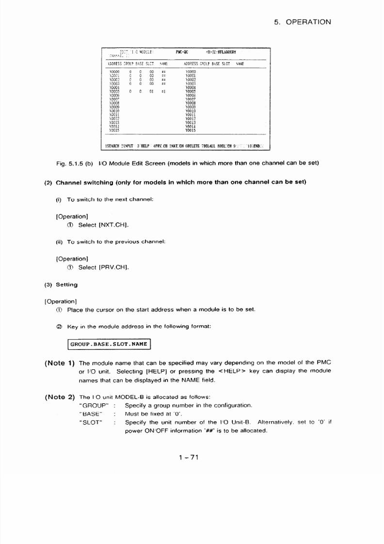
7/25/2019 FAPT Ladder for PC-Operator Manual
http://slidepdf.com/reader/full/fapt-ladder-for-pc-operator-manual 78/302
5. OPERATION
x0000 0
' WOO
0
\ooc2
\0003 ;
\000
yoo~ 0
%’
sooo~
coo10
~0011
\OO ?
xooi3
\OOl?
.\OOlI
i 000
::: \ooooOOQl
:: 1:f 10002003
YOOO4
0 01
:I F0005
FOO06
YOOCi
YOOOS
10009
YOOlO
10011
YOOl?
YOO13
YOOi4
YOOl5
1WKH ?IXPoT 3’BELP 4PKCB 5 4XLUl GDELETEDEL%L8DK’C-i 9.
I O’mB,
Fig. 51.5 (b) Ii0 Module Edit Screen (models in which more than one channel can be set)
(2) Channel switching
(only for models in which more than one channel can be set)
(i) To switch to the next channel:
[Operation]
0 Select (NXT.CH].
(ii) To switch to the previous channel:
[Operation]
ci Select [PRV.CH].
(3) Setting
[Operation]
Place the cursor on the start address when a module is to be set.
Key in the module address in the following format:
GROUP.BASE.SLOT.NAME
(Note 1) The module name that can be specified may vary depending on the model of the PMC
or I’0 unit. Selecting [HELP] or pressing the <HELP> key can display the module
names that can be displayed in the NAME field.
(Note 2) The I,0 unit MODEL-B is allocated as follows:
“GROUP” : Specify a group number in the configuration.
“BASE” : Must be fixed at ‘0’.
“SLOT” : Specify the unit number of the PO Unit-B. Alternatively. set to ‘0’ if
power ONjOFF information ‘##’ is to be allocated.
l-71

7/25/2019 FAPT Ladder for PC-Operator Manual
http://slidepdf.com/reader/full/fapt-ladder-for-pc-operator-manual 79/302
5. OPERATION
(4) Deletion [DELETE] [DELALL) [DEL.CH]
(i) To delete one module:
‘[Operation J
@ Place the cursor at the address where the module is to be deleted.
0 Select [DELETE].
(ii) To delete all modules:
[Operation] ” +
0 Select [ DELALL].
(iii) To delete the modules of one channel (for models in which more than one channel can be
set):
[Operation 1
@ Select a channel for deletion.
8 Select (DEL.CH].
(5) Search [SEARCH]
[Operation]
@ Press [SEARCH] after an address is specified.
8 Place the cursor at the specified address.
(6) END [END]
[Operation]
On the edit screen, press [END] or < ESC >.
The following message appears.
/I
Select one of the above items. and return to the edit menu.
l-72

7/25/2019 FAPT Ladder for PC-Operator Manual
http://slidepdf.com/reader/full/fapt-ladder-for-pc-operator-manual 80/302
5. OPERATION
(7) Termination [END]
[Operation]
0 Select [END] or press the < ESC > key on the editing screen.
@ The following message appears.
Fl
Update
F2
Quit
F-3
Edit
@ Press the desired function key. The system returns to the editing screen.
5.1.6 System parameter editing
(1) Start
[Operation]
0 Select [SYSPRM] (SYSTEM PARAMETER) from the editing menu.
G3 The system parameter editing screen appears.
The screen shown below is the system parameter editing screen for PMC-FIB. For each
PMC model, see item (4) below.
(2) Input
[Operation]
(J,) Select an input item (displayed in reverse video) with the < 1 7 and < 1 > keys
Q Enter data
For information about Input items, see Item
(4)
below
1-73

7/25/2019 FAPT Ladder for PC-Operator Manual
http://slidepdf.com/reader/full/fapt-ladder-for-pc-operator-manual 81/302
5. OPERATION
(3) Termination
[Operation]
(4)
0 Select [END] or press < ESC > on the editing screen.
@ The following message appears:
II
@ Select a function key from the above. The screen display returns to the editing menu.
System parameter editing
screen and input items for each PMC model
(a)
PMC-L/M
[Editing screen]
0 PMC-L
j ) BCD ?- DI GI TAREA
OBYTE
F' K YPE =L
R-AREA 0
(
S:i,%;O:
81 11
s
0 Xo
0 400
l-74

7/25/2019 FAPT Ladder for PC-Operator Manual
http://slidepdf.com/reader/full/fapt-ladder-for-pc-operator-manual 82/302

7/25/2019 FAPT Ladder for PC-Operator Manual
http://slidepdf.com/reader/full/fapt-ladder-for-pc-operator-manual 83/302
5. OPERATION
3 TIMER USED AREA (area used for timers1
When timers are set with the TMR function instruction on the CRT/MDI, setting and
display in BCD is possible.
This parameter specifies the size (in bytes) of an area that can be set and displayed in
decimal format. This area is allocated from the start (D300) of nonvolatile memory.
This area must be specified in the TMR instruction parameter of timer control data
address to enable decimal display.
A timer control data address requires five bytes. Therefore, this parameter must be set
as follows:
@ COUNTER USED AREA (area used for counters)
When the preset values of counters are set with the CTR function instruction on the
CRT/MDI, setting and display in BCD is possible.
This parameter specifies the size (in bytes) of an area to use for decimal setting and
display. This area is allocated after the TIMER USED AREA in nonvolatile memory.
This area must be specified in the CTR instruction parameter of counter control data
address to allow decimal display.
A counter control data address requires five bytes. Therefore, this parameter must be
set as follows:
(Number of counters for decimal display) x 5 bytes
@ BCD 4-DIGIT AREA (area for settinq/disolav in four-diait BCD)
This parameter specifies the size (in bytes) of an area used to store addresses that can
be set and displayed on the screen (CRTIMDI) in 4-digit BCD. This area is allocated
after the COUNTER USED AREA in nonvolatile memory.
Two bytes are required for four-digit BCD display.
Therefore, this parameter must be
set as follows:
(Number of addresses for 4-digit BCD display) x 2 bytes
@ BCD 2-DIGIT AREA (area for settinq and disolavinq in two-diait BCDl
This parameter specifies the size (in bytes) of an area used to store addresses that can
be set and displayed on the screen (CRTIMDI) in two-digit BCD. This area is allocated
after the BCD 4-DIGIT AREA in nonvolatile memory.
One byte is required for two-digit BCD display. Therefore, this parameter must be set
as follows:
l-76

7/25/2019 FAPT Ladder for PC-Operator Manual
http://slidepdf.com/reader/full/fapt-ladder-for-pc-operator-manual 84/302
5. OPERATION
LADDER EXEC (ladder execution time)
This parameter sets an incremental processing time for the first and second ladder
levels.
This setting reduces ladder scan time, thus achieving high-speed ladder
execution.
Note, however, that increased ladder execution time on the first and second levels
reduces ladder processing time on the third level.
Initial value 100
Setting range 100 to 200
CYCLE TIME
This parameter specifies a sequence program execution period of 16 or 8 ms.
Initial value 0 : 16 ms
Setting 0: 16ms/l :8ms
Note, however, that this parameter cannot be set with PMC-L and PMC-M (MMC);
PMC-L is always set to 16 ms, and PMC-M (MMC) is always set to 8 ms.
IGNORE DIVID CODE (division/non-division method)
This parameter specifies whether to use the ladder division method or non-division
method.
Note that when the non-division method is specified, the third-level ladder is not
executed.
I
nitial value 0 : Division method
(b) PMC-P
[Editing screen]
Setting 0 : NO (division method)
1 : YES (non-division method)
I
l-77

7/25/2019 FAPT Ladder for PC-Operator Manual
http://slidepdf.com/reader/full/fapt-ladder-for-pc-operator-manual 85/302
5. OPERATION
[input item]
@I PMC PARAM. SIZE (0 address size]
This parameter specifies the size (in bytes) of nonvolatile memory in the common
nonvolatile memory (0 address) and internal relay (R address) area.
Initial value 2048 Setting range 0 to 2048
In the initial state, no internal relay (R address) can be used. Be sure to specify this
input item when using an internal relay.
(c) PMC-N/N (I/O LINK)/OA
[Editing screen]
@ PMC-N/N (I/O LINK)
P iZ
TYPE =
K
(I/O LI Xx)
@ PMC’QA
I
EDT iSWEl PAtIWMER~
4050 series
( O: BI CARF. l : BCD
10: : ; 100 - 150s
0:
1 0. W 1: YES
PUC TYPE j PA
l-78

7/25/2019 FAPT Ladder for PC-Operator Manual
http://slidepdf.com/reader/full/fapt-ladder-for-pc-operator-manual 86/302
5. OPERATION
[Input item]
COUNTER DATA TYPE
This parameter specifies whether the format of a counter value used with the CTR
function instruction is to be binary or BCD.
initial value 0 : BINARY Setting 0 : BINARY / 1 : BCD
LADDER EXEC (ladder execution time)
This parameter specifies an incremental processing time for the first and second ladder
levels.
This setting reduces ladder scan time,
thus achieving high-speed ladder
execution.
Initial value 100 Setting range 100 to 150
The table below indicates ladder execution time status during an execution period of 8
ms.
I
Setting
1
First and second level processing time
100%
1 ~~~~
ms
150% 7.5ms
Note, however, that increased ladder execution time on the first and second levels
reduces the following processing times:
PMC screen display time
CPASCAL processing time
Ladder processing time on the third level
PASCAL EXEC (PASCAL execution time)
This parameter specifies the ratio of C/PASCAL execution time to ladder program
execution time.
In contrast to LADDER EXEC, this parameter reduces ladder processing time on the
first and second levels, and increases processing time for PASCAL and similar
processing.
r
nitial value 0
I
Setting range 0 to 100
I
PASCAL EXEC RATIO (ratio of PASCAL processino time to PMC screen processin@
The initial setting gives the same priority to C/PASCAL processing and PMC screen
display. This parameter allocates processing time to the following:
PMC screen display time
C/PASCAL processing time
Ladder processing time on the third level
Under this setting, PASCAL can run periodically even during PMC screen display.
l - 79

7/25/2019 FAPT Ladder for PC-Operator Manual
http://slidepdf.com/reader/full/fapt-ladder-for-pc-operator-manual 87/302
5. OPERATION
r
nitial value 50
1
Setting range to 99
I
When 0% is specified, C/PASCAL is executed after PMC screen display.
Note that if a much greater value is specified in this parameter, the time allocated to
PMC screen display is too short, resulting in a delayed display.
8 PASCAL ORIGIN
This parameter specifies the start address .of the task control block (TCB) of a PASCAL
program.
Initial value Setting range Address in the PASCAL area
I
When there is no PASCAL program, specify OOOOOOH.
@ PASCAL DATA ORIGIN
This parameter specifies the start address (physical address) of the data area for a
PASCAL program.
Initial value 000000
Setting range Address in the PASCAL area
I
When OOOOOOH s set in the PASCAL DATA ORIGIN parameter, %FF4000H (or
sb800000H when an optional RAM is used) is assumed as the address.
@ SYNCHRONIZED LEVEL 3 (third-level svnchronization)
This parameter specifies whether to allow the synchronous buffer to be used in level 3.
Initial value 0 : NO Setting 0 : NO / 1 : YES
@I PMUOS EDITION fmanaaement software edition)
This parameter specifies the edition of the management software used with PMC-N.
Initial value 01 Setting Edition of the management software currently used
l-80

7/25/2019 FAPT Ladder for PC-Operator Manual
http://slidepdf.com/reader/full/fapt-ladder-for-pc-operator-manual 88/302

7/25/2019 FAPT Ladder for PC-Operator Manual
http://slidepdf.com/reader/full/fapt-ladder-for-pc-operator-manual 89/302

7/25/2019 FAPT Ladder for PC-Operator Manual
http://slidepdf.com/reader/full/fapt-ladder-for-pc-operator-manual 90/302
5. OPERATION
The table below indicates ladder execution time status during an execution period of 8
ms.
Setting First and second level processing time
100%
5ms
150%
7.5ms
Note, however, that increased ladder execution time on the first and second levels
reduces the following processing times:
PMC screen display time
Language program processing time
Ladder processing time on the third level
@ IGNORE DIVID CODE (division/non-division method)
This parameter specifies whether to use the ladder division method or non-division
method.
Note that when the non-division method is specified, the third-level ladder is not
executed.
I
nitial value 0 : Division method Setting 0 : NO (division method)
1 : YES (non-division method)
I
@ LANGUAGE EXEC RATIO
As the language program and PMC screen display have the same priority, this
parameter specifies the percentage of the following processing times:
PMC screen display time
Language program processing time
Processing time of third-level Ladder program
While the PMC screen is displayed, a language program can be executed cyclically.
llnitial value 50 1 Setting range 0 to 99
@ LANGUAGE ORIGIN
This parameter specifies the start address of the link control statement data of a
language program.
Initial value 000000
Setting range Address in the language program storage
area
When there is no language program, specify OOOOOOH.
1-83

7/25/2019 FAPT Ladder for PC-Operator Manual
http://slidepdf.com/reader/full/fapt-ladder-for-pc-operator-manual 91/302
5. OPERATION
@ OPERATOR PANEL (connectinq an FO machine operator’s oanel)
This parameter specifies whether a machine operator’s panel is used with the FSO.
When YES is specified in this parameter, specify the Dt’DO addresses where the
operator’s panel is actually connected, an address for key images transferred from the
operator’s panel, and an addresses for LED images transferred to the operator’s panel.
Initial value 0 : NO Setting 0 : NO i 1 : YES
I
0
.-
,,
ii)
iii)
iv)
KEY DI DDRESS
Specify the start address (PMC address) of the external Dl where the operator’s
panel’ is actually connected.
Setting range X0 to Xl 27,
Xl 000 to Xl 019
KEY DO DDRESS
Specify the start address (PMC address) of the external DO where the operator’s
panel is actually connected.
Setting range YO to Y127, YlOOO to Y1014
KEY BIT IM GE DDRESS
Specify the start address (PMC address) of key images referenced by user
programs.
Usually an arbitrary internal relay area is set.
LED BIT IMAGE ADDRESS
Specify the start address (PMC address) of LED images referenced by user
programs.
Usually an arbitrary internal relay area is set.
l-84

7/25/2019 FAPT Ladder for PC-Operator Manual
http://slidepdf.com/reader/full/fapt-ladder-for-pc-operator-manual 92/302
5. OPERATION
5.2 Printout
A sequence program can be printed out.
When PC9801 is used, PRINT.SYS must be installed
beforehand. Install PRINT.SYS according to Section 2.1 .l.
For printout, FAPT LADDER allows the user to set the top margin, left margin, line spacing and
cross reference. For details on setting, see Section 1.4 of Part II.
Compatible printers
This software is usable with the printers listed below.
NEC PC9801
I
IBM PC/AT
NEC PR201H
EPSON VP1000 (Note)
EPSON VP1000
(Note) To use an Epson VP1 000 with an NEC PC9801, a program modification is required. For
details, see Section 1.4 of Part II.
(1) General flow of operation
for printout
-
elect a source program
Make # LS file
[ EXEC]
End -[ EXEC]
<Fl > <Fl>
v
Specify output item
Fig. 5.2 (a) Operation Flow and Screens
l-85

7/25/2019 FAPT Ladder for PC-Operator Manual
http://slidepdf.com/reader/full/fapt-ladder-for-pc-operator-manual 93/302

7/25/2019 FAPT Ladder for PC-Operator Manual
http://slidepdf.com/reader/full/fapt-ladder-for-pc-operator-manual 94/302
5. OPERATION
The step sequence diagram printing can be selected at PMC-RB4(STEP) 1 RC4(STEP).
1)
2)
:iliiiiliiiiiiiiiiii~~~pR~N~~~~~~~~~~~~~~~~~~~~~~
’ 4
C:FRC4-STEP
TITLE : @#I/YES1
SYSTEMARAMETER
: [ WYESl
SYMBOL COMENT
: WYESI
LADDERIAGRAM
f mT;l;;
: [OPTION]
Added -> ~~...-I
,um
:
[OPTIONI
I/O UODULE
: WYESI
MESSAGE
: [Em/YES1
: [OPTION]
CROSS EFERENCEIST
: [CWYESI
: [OPTION]
BIT ADDRESS AP
: #tU/YESl
Fig. 5.2 (d) Printing menu
C:YRC4-STEP
.fil::l:i
FIO (
ESC 1 :
END
11
Fig. 5.2 (e) Optional setting menu for step sequence diagram printing
PRINT UNIT
Select either only a specified sub-program or all sub-programs.
When selecting “MODULE”, specify the printing sub-program name to “MODULE NAME”.
SUB-PROGRAM NUMBER
Select either not printing / printing sub-program number which belongs to a step sequence
program.
l-87

7/25/2019 FAPT Ladder for PC-Operator Manual
http://slidepdf.com/reader/full/fapt-ladder-for-pc-operator-manual 95/302
5. OPERATION
(4) Output item setting
Items to be output to a drawing are specified as described below. More than one item can be
specified at a time. Some set items may not be displayed, depending on the model of the
PMC.
@ Specifying whether to output each data item
Whether to output each data item can be specified by placing the cursor on the desired
item on the output item select menu with the 7 or 1 key, then pressing the <RETURN>
key.
8 Specifying options
For data having optional items, place the cursor on the desired option, then press the
<RETURN > key. The screen for specifying the corresponding option will appear. After
entering the necessary value on that screen, press the < RETURN > key.
6 Detail of each data time
1) Title printing
The data of the title is printed.
2) Parameter printing
The data of the system parameters is printed.
3) Symbol printing
The symbol comment data is printed.
i) Option (symbol printing)
* The output range of symbol comments to be printed is specified. If “0” is
specified as the print end line number, printing continues up to the last line.
4) Ladder diagram printing
A ladder diagram is printed.
i)
Option (ladder diagram printing)
* The output unit, net range, page break, and cross-reference of a ladder
diagram to be printed are specified.
* If a diagram is output as a list file, the unit of printout must be specified as a
module.
* If “0” is set as the output end net when a range of nets is specified, printing
continues up to the last net.
. If a page break is specified, a page break is made in the ladder diagram at
every new file or subprogram.
* If a cross-reference is specified, the ladder diagram is accompanied with a
cross-reference. (Fig. 5.2 (c))
5) I’0 module printing
The I/O module data is printed.
6) Message printing
The message data is printed.
i) Option (message printing)
* The range of messages to be printed is specified.
l-88

7/25/2019 FAPT Ladder for PC-Operator Manual
http://slidepdf.com/reader/full/fapt-ladder-for-pc-operator-manual 96/302
5. OPERATION
. Print format specification
Either Japanese-language (Japanese-language input mode screen) or code
format (code input mode screen) is selected.
7) Cross-reference list printing
A cross-reference list is printed. (Fig. 5.2 (d))
i) Option (cross-reference list printing)
* When a cross-reference list is printed, a check is made for duplicate writing,
and the output range of addresses is specified. If a duplicate write check is
specified, a message is displayed for duplicate writing of a write coil and
duplicate use of a function instruction that uses a number (such as a timer and
counter). The range of output addresses can be specified according to the
following table.
Table 5.2 Cross-Reference List Address Specification
I
I
Address specification mode
Example of
keying in
Address to be output
ALL
ALL
Initial letter of an address
Y
Bit address
R1.O
Byte address
x10
All addresses
All addresses having a specified initial letter
Specified bit addresses only
Specified byte addresses
(including bit addresses)
Address range I
F10.0.F12.7
I
All addresses in a specified range
X2.3.END
(Note 1)
All addresses after a specified address
(Note 1) When an address specification is made, addresses are output in the sequence: X. Y,
F, G, R, A, C, K, D. T, variable address, P. In this example, therefore, Y and all
subsequent addresses are output.
8) List file printing
Data from a list file is printed.
Fig. 5.2(f) Example of Printout of a Ladder Fig. 52(g) Example of Printout with a
Diagram with Cross Reference Data
Multiple coil Write Check Indication
l - 89

7/25/2019 FAPT Ladder for PC-Operator Manual
http://slidepdf.com/reader/full/fapt-ladder-for-pc-operator-manual 97/302
5. OPERATION
Example of printout of step sequence diagram
(1) Printout example by “F2[SETUP]” (print menu)
c graphical mode printout >
Initial step
Transition
Label
q 210
PlOl
-h
e Divergence of selective
P150
P160 sequence
+-- Divergence of
I simultaneous
0 S211 0 S215 0 S217 sequence
P151
t t
P161 1 P165
+Convergence of
P152
P162 simultaneous
sequence
0 S212 0 S216
~
Step
P163
P164
f- Convergence of selective
sequence
Block step
Jump
<ASCII mode printout >
.
;* Sl
t
Initial step
: Pl
.
+ PlOO 4
Transition
c-L1
4
Label
s210
: PlOl
c- Divergence of selective
+ P150
+ P160 sequence
+- Divergence of
.
S211 ’ S215 ’
simultaneous
S217 sequence
: P151 : P161
: P165
.
-Convergence of
+ P152 + P162 simultaneous
.
sequence
S212 ’ S216 - Step
: P153
: P163
+ P154 + 164
c- Convergence of selective
F;’ SlOOO 4
sequence
Block step
: P2000
+ P102
->Ll
4
Jump
(2) Printout example by “SUB-PROGRAM NUMBER [NONES]”
<Not print sub program number > <Print sub program number >
&IS1
4-
lOO
c-L1
q 210
jG+G-j-
P160
- Sub program number
P160
l-90

7/25/2019 FAPT Ladder for PC-Operator Manual
http://slidepdf.com/reader/full/fapt-ladder-for-pc-operator-manual 98/302

7/25/2019 FAPT Ladder for PC-Operator Manual
http://slidepdf.com/reader/full/fapt-ladder-for-pc-operator-manual 99/302
5. OPERATION
(5) Specification of output forms
Specify the paper size and the type of printer forms.
[Operation ]
0 Select [SETUP] on the output item selection screen.
@ The forms selection screen appears (Fig. 5.2(h)).
I
P P\ PERI ZE / LADDERPRI ST
:
10 I NCH
ASCI I
* 10 Pi CH
GRAPHI C
15 I NCH
ASCI I
15 I KCH GRAPHI C
Fig. 5.2(h) Forms Selection Screen
0 Current output form is indicated with *. To change the output format, move the cursor by
< t >orc J >andenter<RETURN>.
@I After selecting forms, select [END) to return to the output item selection screen.
(6) Start of printing
[Operation]
Select [PRINT] on the output item selection screen.
Printing is started: during printing, the indication “PRINTING IN PROGRESS” blinks on the
screen.
When printing ends, the indication
“PRINTING IN PROGRESS” disappears. (To stop
printing halfway through, select [BREAK]: the screen display returns to the input program
specification screen.)
(7) Termination
[Operation]
l - 92

7/25/2019 FAPT Ladder for PC-Operator Manual
http://slidepdf.com/reader/full/fapt-ladder-for-pc-operator-manual 100/302
5. OPERATION
$ Select [END] on the input program specification screen or the output item selection
screen.
8 The screen display returns to the main menu screen.
(8) [LIST] command (F2 KEY)
It is the same function as “53.1 The List of source program”.
refer to above paragraph.
Note) If the step sequence function is selected when setting a model, the function for printing
a diagram according to a specified control statement (file with extension .#LS) is not
supported. The [LIST] command for creating a control statement is not included in the
displayed function key menu and cannot be executed.
(9) The note if the step sequence function is selected when setting a model
1) Net Numbers
When a ladder diagram is edited, net numbers starting from 1 are assigned to
subprograms. When a ladder diagram is printed, sequential numbers are assigned to all
subprograms in ascending order of subprogram numbers.
2) Cross Reference
A cross reference can only include information referenced by the ladder, first, second, or
third level, or by ladder subprograms. If ladder subprogram PO001 is referenced only by a
step sequence subprogram, and if address PO001 is specified to print the cross reference,
there is “no reference information.”
3) Printing the Step Sequence Diagram
The step sequence diagram cannot be printed.
l - 93

7/25/2019 FAPT Ladder for PC-Operator Manual
http://slidepdf.com/reader/full/fapt-ladder-for-pc-operator-manual 101/302
5. OPERATION
5.3 Compilation
During compilation, an edited source program is translated into a ROM format file (object file)
executable by the PMC. Uncompiled programs cannot be transferred to the ROM writers (PMC
writer or FA writer) or RAM for the PMC. With PMC-R series, PMC-QC, PMC-NB. compilation can
be performed in one of two modes:
normal mode and condensed mode.
$$g - = - @ - andPMC
Transferred to the ROM writers
Condensed mode
With PMC-R series, PMC-CC, PMC-NB, a source program can be compiled in condensed
mode. When a ladder with the same number of steps is compiled in condensed mode, the
size of the created ROM format file is smaller than that created in normal mode. As a result,
condensed mode has the advantages listed below.
@ A larger C language area can be allocated.
Normal mode Condensed mode
ROM format file
Ladder
C
language
0 Time required for compilation is reduced.
0 Time required for transfer from the personal computer to the PMC is reduced.
@ A ROM module with a smaller capacity may be used.
l-94

7/25/2019 FAPT Ladder for PC-Operator Manual
http://slidepdf.com/reader/full/fapt-ladder-for-pc-operator-manual 102/302
5. OPERATION
On the other hand, condensed mode has the restrictions described below.
0
8
5.3.1
Memory map changes (area expansion) are likely to occur when instructions, symbols,
comments, and so forth are added when a ROM format file generated by compilation in
condensed mode is transferred to the PMC and edited with the built-in editing function. In
this case, the user needs to pay attention to possible overlap between the ladder area and
C language area.
ROM format file
1
Overlap (A C language program
map change is required.)
language 1
A ROM format file generated by compilation in condensed mode cannot be compared with
a ROM format file generated by compilation in normal mode.
Operation
(1) Start
[Operation]
a Select [COMPILJ (compile) from the main menu.
8 The compile screen appears (Fig. 5.3).
Comple
[email protected]>y<y?$y@gQ
\.i\.\ \.._,.,\
Sour ce r ogramame : A: YFLYi I ATAYTEST
ROWf or mat i l e name : A: YFLYDATAYTEST. t El
/
Seri es
Edi l i on
&chi ne tool name
VC L PUC name
Pr ograme o.
/
~--- -
Fig. 5.3 (a) Compile Screen
l - 95

7/25/2019 FAPT Ladder for PC-Operator Manual
http://slidepdf.com/reader/full/fapt-ladder-for-pc-operator-manual 103/302
5. OPERATION
General Flow of Operation for compiling
I
Main menu
I
$yg
Make#LSi’e
Main menu
Fig. 5.3 (b) Compiling General Operation and Screens
(2) Compiling
.- (a) Normal mode
When PMCPAljPA3 is used, selecting [EXEC] causes programs to compiled in the
condense mode.
[Operation]
@ Specify a source program name and ROM format file name. The ROM format file
name must conform to the MS-DOS specifications.
@ Select (EXEC].
Note) For PMC-PAlIPA3. compilation in condensed mode is done by [EXEC].
Q Compilation is performed in the normal mode.
@ When the compiler terminates normally, memory map information is output. When the
compiler terminates abnormally, an error message is output.
(b) Condensed mode
Compilation in condensed mode can
only be performed
with PMC-R series PMC-QC’PMC-
NB.
[Operation]
0 Specify a source program name and ROM format file name. The ROM format file
name must conform to the MS-DOS speciftcations.
8 Select [CONDNS]
Q Compilation is performed in condensed mode.
l-96

7/25/2019 FAPT Ladder for PC-Operator Manual
http://slidepdf.com/reader/full/fapt-ladder-for-pc-operator-manual 104/302
5. OPERATION
9 When the compiler terminates normally, memory map information is output. When the
compiler terminates abnormally, an error message is output.
(3)
Output of compiling result
The results of compilation are output to the screen displayed by [ERROR](F3
key)
and to the
following text files, irrespective of whether an error or warning has been issued. If many errors
occur, it is convenient to print out pr check the error fife with the text editor.
1) If the step sequence function is selected when setting a model, and if the following sample
source program is edited, the error and warning messages are output to the following file.
- Error file name
= “TEST.ERR”(depending on the source program)
Compiler
RCBGTEPEQ) [A:YFLYDATAWFCY
source progr m name : A:YFLYDATAYTEST
ROM
ormat
file name
:
A:YFLYDATAfTEST.EX
1
- Output directory
= “A: Y FLY DATA% ”
Series
Edition
Machine tool name
NC& PMC ame
Program no.
I
2) In other case than 1) above, the error and warning messages are output to the following
file.
- Error file name =
“FLMNE.ERR”(fixed name)
- Output directory =
“in which the FAPT LADDER system is stored”
(4) Termination
[Operation]
3
Select [END).
C?9 The screen display returns to the main menu screen.
l - 97

7/25/2019 FAPT Ladder for PC-Operator Manual
http://slidepdf.com/reader/full/fapt-ladder-for-pc-operator-manual 105/302
5. OPERATION
(5) Specification of the input program name
(a) Specification of the input program name
It is possible to specify the extension of its input program name as following 3 types.
(Please refer to “1.1.2 compilation function” about #LS.)
* #LS
* #CN * No extension
Specify the file WITH its extension
It is possible to select the file name with its extension for the #LS-file and the source
program file.
Example for the #LS-file.
TESTDATA. LS
File name -
Example for the source program file.
TESTDATA. CN
File name -
Specify the file WITHOUT its extension
In case of there are some same file names (without its extension) for the #LS-file and
the source file, target file is selected by system.
The order of priority for the target file specification is shown below.
1 The #LS-file
2 The source program file
In case of inputting the source program file, please select the file name with its
extension.
(b) Changing the file name after using “the making # LS file”
In case of after using “the making # LS file” function with #LS-file, the input program name
is changed to the LS-file name with its extension.
(6) [LIST] Command (F4 KEY)
It is possible to use following functions by [LIST].
1)
The list of source program indications
2) Making “.#ls”-file
The “.#ls”-file name which is made by [LIST] function. is set into the space for source program
name.
Refer to next page about the details of above mentioned.
l - 98

7/25/2019 FAPT Ladder for PC-Operator Manual
http://slidepdf.com/reader/full/fapt-ladder-for-pc-operator-manual 106/302
5. OPERATION
Note) If the step sequence function is selected when setting a model, the link compile
function specified by the control statement,“file with extension .#LS”, is not used. The
[LIST] command, used to create a control statement, is not included in the function key
menu and cannot be executed.
(7) Indications of compilation result
MAIN.#LS
c
Specified source program name
##### PASS1 ###I#
+-Compilation result PASS 1
B:rb FLADDERY RC3ab MAIN
Source
program name
B:Y FLADDERY RC3+ I-STEP
(“MAIN.#LS”)
B: Y FLADDERS' MODULE+ SUBPl
B:a( FLADDERY MODULEY SUBPZ
B:Y FLADDERY RC3+ END-STEP
####t PASS2 #####
tcompilation result PASS 2
B:Y FLADDERY
B:M FLADDERY
B: + FLADDERY
Error
end 20
B: Y FLADDERY
Error end 31
B:Y FLADDERY
RC3Y MAIN
RC3Y l-STEP
MODULE+ SUBPl
MODULEM SUBPZ
RC3M END-STEP
(00111 Net ) -
(00001 Net )
compile completed error count=00002
warning count =OOOOO
PASS 1: Convert to object
PASS 2: Syntax check
5.3.2 Password set function
(PMGRAl/RA3/RB3/RB4/RB5/RB6/RC3/RC4/NB/NB2)
This function is supported only in the FS16/18/21 -B.
It enables a password to be added during compilation.
The password can be used to prohibit ladder programs from being
CRT:MDI. To discompile a ladder program guarded with a password,
password correctly.
(a)
Password types
There are two password types.
Each password consists of up to 8 alphanumeric characters.
Relative net
number in
each
program
displayed or edited on
the
it is necessary to enter the
Type
Use
Password (R)
Password to allow display on the FSlG-B
Password (R/W) Password to allow display and editing on the FSlG-B
I
l-99

7/25/2019 FAPT Ladder for PC-Operator Manual
http://slidepdf.com/reader/full/fapt-ladder-for-pc-operator-manual 107/302
5. OPERATION
(b) How to specify use of a password
To use a password, set as follows:
0 Open the initial set file (%%%FLSET.CNF), using a commercially available editor.
(cl
Password setting (compile)
:
FAPT LADDER Initial Setting File
:
;
Text Editor
:
:
editor =;
rpl_dha = ;
ladkey ‘1;
password=O;
:
: t
j-1
:
*tJ;
0:No password
1:Password (R/W) and (R)
2:Password (R/W)
3:Password (RI
@ Specify whether to use a password and the type of a password (when used) after
password = .
Value Password type
0 No password is used.
1
Both password types R and RW are used.
2 Password type RW is used.
3 Password type R is used.
Q When password = 0 + Gotoo.
When password = 1. 2, or 3:
After compilation [EXEC] or [CONDNS] is selected, you will be prompted to specify
whether to use a password.
I
o you enter password? (Y/N)
I
To set a password. press Y
cl
+ If password = 1 or 3, go to 0.
If password = 2, go to @.
If it is unnecessary to set a password, press N
cl
+ Go to @.
l-100

7/25/2019 FAPT Ladder for PC-Operator Manual
http://slidepdf.com/reader/full/fapt-ladder-for-pc-operator-manual 108/302
5. OPERATION
@ The password (R) set screen appears.
Enter password (R)
@ Enter a password.
. A password that can be used is a combination of 8 or less letters and.;or numerals.
* Uppercase and lowercase letters are not distinguished from each other. (If a lowercase
letter is entered, it is assumed to be uppercase.)
* It is impossible to use space, kana. kanji, and special characters (such as #, and @).
. Some character strings are unusable.
If
one such character string is entered as a password, an error message is displayed.
In such a case, use another character string.
* An entered password is not displayed on the screen.
* If the <RETURN> key is pressed before any valid password is specified, use of a
password is not specified. -, If password = 1,
go
to @.
If password = 3, go to @.
* When <ESC> is pressed, an attempt to specify a password is discontinued.
-+ GotoO.
@ The password configuration screen appears.
Verification (R)
I
0 You will be prompted to enter the same password as entered before, to ensure that your
password was entered correctly.
* When the password entered this time matches one that was entered before, it is
accepted.
. When they do not match, the message “Password mismatch” is displayed.
You are allowed to retry entering twice.
- When <ESC> is pressed, an attempt to specify a password is discontinued.
+ Go tom.
If password = 3 is specified.
+ Go to@.
@ The password (R#V) set screen appears.
Enter password (R/W)
0 Enter a password (R/W).
- A password that can be
used is a combination of 8 or less letters
and or numerals.
. Uppercase and lowercase letters are not distinguished from each other. (If a lowercase
letter is entered, it is assumed to be uppercase.)
. It is impossible to use space. kana. kanji. and special characters (such as *, #, and @).
. Some character strings are unusable.
If one such character string is entered as a password, an error message is displayed.
In
such a case, use another character string.
1- 101

7/25/2019 FAPT Ladder for PC-Operator Manual
http://slidepdf.com/reader/full/fapt-ladder-for-pc-operator-manual 109/302
5. OPERATION
.
An entered password is not displayed on the screen.
1
If the <RETURN> key is pressed before any valid password is specified, use of a
password is not specified. + Go to@.
-
When c ESC > is pressed, the attempt to specify a password is rejected.
+ Go too.
@ The password confirmation screen appears.
Verification (R/W)
@ You will be prompted to enter the same password as entered before, to ensure that your
password was entered correctly.
-
When the password entered this time matches one that was entered before, it is
accepted.
- When they do not match, the message “Password mismatch” is displayed.
.You are allowed to retry entering twice.
-
When -z ESC > is pressed, the attempt to specify a password is rejected.
-+ Go to@.
@ Compilation begins.
(d) Password entry (discompile)
To discompile a password-protected ROM format file, it is necessary to enter a password.
I
Set password type
I
Password type to be entered
IBoth password types (R) and (R.W)
Password type (R/W)
Password type (R)
Password type (R/w)
Password type (RMI)
Password type (R)
After discompilation [EXEC] is selected, the following password entry screen appears
Enter password (R)
-1 Note)
If an RMI password has been set
up, “password (R.‘W)” is
displayed.
When the valid password is entered, discompilation begins.
If the newly entered password is incorrect, an error message is displayed, and processing
discontinues.
(You are allowed to retry entering twice.)
When <ESC> is pressed, the request to start discompilation is rejected.
l - 102

7/25/2019 FAPT Ladder for PC-Operator Manual
http://slidepdf.com/reader/full/fapt-ladder-for-pc-operator-manual 110/302
5. OPERATION
5.3.3 Changing the Order of Subprograms
When a program is compiled. the source program, subdivided i ntosubpr ogr ams, is converted to a
single ROM file. Within the ROM file, subprograms are arranged in ascending order of subprogram
numbers. The order in which subprograms are displayed on the edit screen of the built-in
programmer function of the PMC-RB4 or PMC-RC4 may be changed after the source program has
been uploaded to FAPT LADDER, decompiled, compiled, and downloaded.
5.3.4 It is possible to choose output data
(Symbol/Comment, Net comment) to ROM format file
Compi l e PMC- RB4 <O>[ A: YFLYDATAf RB4
Sourceprogram name
: A:
YFLYDATAYRB4
ROM
format file name
: A: YFLYDATAYRB4. #EX
Output t o ROMor mat i l e
SYMBOLi COkHENT
[F61
YES
NETCOMENT
tF71
PO1NTERSONLY
Compi l e
PMC- RB4
<O>[ A: YFLYDATAFRB4
Sourcepr ogr amname
: A:
YFLYDATAYRB4
ROMf or mat i l e name
: A:fFLYDATAYRB4.EX
_..:.:..::.‘~
::::..::.
Compi e nor mal end ~. . : . . . : : : : : j : : : . . . : : ~.
:: :
compi l ecompl et ed
er r or count = 000000 warni ngcount = 000000
1
EXEC 2 MAP 3 ERROR 4 5 F, SYMBOL 7
NETCMT 8 CONDNS g DOS 10
END
Fig.
53.4 (b )
Compile end
l - 103

7/25/2019 FAPT Ladder for PC-Operator Manual
http://slidepdf.com/reader/full/fapt-ladder-for-pc-operator-manual 111/302
5. OPERATION
(i) F6 [SYMBOL]
Select whether output or not output the symbol 8 comment data to ROM format file.
HoweverJhe symbols which can not be displayed on CRTiMDl (7bytes or more symbols)
and the coil comments assigned to them never output to ROM format file.
1)
“YES”: (Default setting)
The symbols which can be displayed on CRT/MDl(Gbytes or less symbols) and the coil
comments assigned to them are output to ROM format file.
They can be displayed on CRT/MDI.
2)
"NO" :
No symbofcomment is converted to ROM format file.
Any symbol and comment is not displayed on CRTIMDI.
(ii) F7 [NETCMT]
If Net comment is used in ladder program, you can choose whether ‘Net comment pointer’
(Note2) is output to ROM format file or not.
1)
“POINTERS ONLY” : (Default setting)
To edit the ladder program by CNC built-in editor and decompile the data by FAPT
LADDER, select this setting.
However, ladder size gets larger because ‘Net comment pointer’ is output to ROM
format file.
2)
"NO"
:
Any ‘Net comment pointer” is not output to ROM format file. In this case, ladder size in
the ROM format file is saved.
However, decompile the ROM format file makes its net comment data information lost.
Note 1)
This item is in effect for Source-format programs. At the compilation of FORMAT-B
source-program,this setting is ignored.
Note 2)
Net comment has its own character information only in a source program on the
personal computer.
Compiled ROM format file does not include any net comment characters.
Only ‘Net comment pointer’( =
information of net comment position.) can be
output to ROM format file as an functional instruction “NOP”.
This ‘Net comment pointer” helps to restore net comment date at decompiling the
ROM format file that is edited on CNC built-in editor and uploaded to FAPT
LADDER.
l-104

7/25/2019 FAPT Ladder for PC-Operator Manual
http://slidepdf.com/reader/full/fapt-ladder-for-pc-operator-manual 112/302
5. OPERATION
5.3.5
The list of source program
(a)
The list of source program indications
The file (selected directory) appears.
(4
Making the #LS-file
Please select the source program, and then the #LS-file is registered.
(Note) It is impossible to resister by source program of different PMC type. Because error
occur on print out/compilation operation.
The sequence of making the #LS-file as following flow chart.
Select the list of source program
Display the list of source program
(The target file indications)
Select one of source program
(Register to #LS-file)
(1) Start
(a) Select [LIST] (< F2 >
:
Print out/< F4 >
:
Compilation)
(b) “The list of
source
program” screen appears
The target file indications :
Source program file indications. (Indicated directory)
Indications
. .
DIR
: xxx
Meaning
Parent-directory
Sub-directory
PMC type
l - 105

7/25/2019 FAPT Ladder for PC-Operator Manual
http://slidepdf.com/reader/full/fapt-ladder-for-pc-operator-manual 113/302
5. OPERATION
Selected file indications :
Selected target file is indicated by absolute-pass.
F ig. 5.35 (1) The List of Source Program Screen
(2) Function key indications and selection
The list of source program functions correspond to the function keys as indicated below.
(a) [LIST1 1
EXEC
I
CHANGE EXTEND DRIVE SEARCH END
1 (W
1 (c)
(b) [CHANGE] 1
DELETE INSERT
CHANGE END
(c) [SEARCH) 5
TOP
BOTTOM
FILE
PCTYPE
END
1 (d)
(d) [PCTYPEJ 1
PREV NEXT END
l - 106

7/25/2019 FAPT Ladder for PC-Operator Manual
http://slidepdf.com/reader/full/fapt-ladder-for-pc-operator-manual 114/302
5. OPERATION
(3) Making of #LS-file [EXEC]
The sequence for registration source program file to #LS-file is shown below.
1. Source file indications (The target file indications)
2. The cursor moves to the selection file
3.
Push the <RETURN > key (Registration)
4.
Changing of selected file
(changing of the select file)
5.
Select [EXEC] (Making of the #LS-file + End)
The #LS-file name is changed to the “1st registered file name .#LS”.
Each data (System parameter~TitleSymbol&comment:Message/lO module) is effective in the
1st registered file.
(4)
The list of source program indications
(a) Changing of directory with drive [DRIVE]
Changing of “drive + directory” use [DRIVE] software key.
It is possible to change directory in the same directory by <cursor > keys.
The following message appears after push the [DRIVE].
’ INPUT DRIVE NAME, PLEASE '
Example
Specification of only drive
B:<RETURN>
(Changing to B:)
Specification by absolute-path + drive
B:\DATA<RETURN>
(Changing to B:\DATA)
(b) Changing of file extension [EXTEND]
[EXTEND] is used to change extension (A part of “ 5_ mark on Fig. 53.1 (2).
It is possible to indicate file name except source program by changing extension.
In case of there are some selected files, it is impossible to use this function.
Extension can be changed by [EXTEND]
Fig. 5.3.5 (2) A Part of Target File Indications
l-107

7/25/2019 FAPT Ladder for PC-Operator Manual
http://slidepdf.com/reader/full/fapt-ladder-for-pc-operator-manual 115/302
5. OPERATION
The following message appears after pushing the [EXTEND].
’
INPUT EXCHANGE EXTEND(MAX 3 CHA.) '
Result from specification
File indications (Without extension)
File name with specified extension
Searching for a ‘fle in the source file list
[SEARCH]
Following functions to &arch in the source file list are available.
(4
Searching for the first file [TOP]
The cursor moves to the first file in the current directory.
lb)
Searching for the
last
file [BOTTOM]
The cursor moves to the last file in the current directory.
w
Searching
by file name
[FILE]
Type a filename followed by [FILE].
When specified file exists, the cursor moves to the specified file.
When specified file does not exist, an error message is displayed. And then, it is possible
to continue to search by pressing any key.
To terminates the search function, press < ESC > key or select [EXEC].
(4
Searching by PMC
model
(PCTYPE)
1. Searching for the first file
[TOPI
2. Searching for the last file [BOTTOM]
3. Searching by file name
[FILE]
4. Searching by
PMC model [PCTYPE]
Type a PMC type, for example RC3, followed by [PCTYPE].
When files with specified PMC type exist, the cursor moves to the file. And then, it is
possible to select the file at
th
e cursor position by pressing <RETURN> key. And,
following operations are also allowed.
[PREV] searches backward for the previous occurrence of file with specified PMC type.
[NEXT] searches forward for the next occurrence of file with specified PMC type.
When no file with specified PMC type exrsts, an error message is displayed. And the, it is
possible to continue to search by pressing any key.
To terminates the search function, press < ESC z= key or select [ENDj.
l - 108

7/25/2019 FAPT Ladder for PC-Operator Manual
http://slidepdf.com/reader/full/fapt-ladder-for-pc-operator-manual 116/302
5. OPERATION
(6)
Changing the selected file list
[CHANGE]
Following functions to change the list of selected files are available.
1. Deleting a file [DELETE]
2. Inserting a file [INSERT]
This operation is also used to move the cursor between the source file list area and selected
file
(a)
list area.
Deleting a file [DELETE]
A file at the cursor position is deleted. And, the files following the deleted file are shifted
one line upward on the display.
(b]
Inserting a file [INSERT]
A blank line is inserted at the cursor position and then the cursor moves to the source file
list area.
By selecting a source file in the source file list area, the selected file is inserted at the
blank line and the cursor moves to the inserted file name.
(c]
Terminates the changing of selected file list [END]/ < ESC >
Function to change the selected file list terminates.
(7)
Terminating [END ]/ < ESC >
The source program listing function terminates.
In this case no .#LS file is created.
5.3.6
DOS
command
You can call MS-DOS shell from FAPT LADDER by pushing [DOS] key.
If you want to terminate this, key in the command as bellow at MS-DOS command line.
1 A:bEXIT 1
l-109

7/25/2019 FAPT Ladder for PC-Operator Manual
http://slidepdf.com/reader/full/fapt-ladder-for-pc-operator-manual 117/302
5. OPERATION
5.4 Decompilation
During decompilation, a
printed out.
ROM format file is translated into a source program that can be edited or
Data that is uploaded from the PMC or is read from ROM is ROM format file data. Data in the
ROM format file cannot be edited or printed out. Such data must be decompiled before it can be
edited or printed out.
(Note)
To discompile a password-protected ROM format file, it is necessary to enter a
password. (See Section 5.3.)
5.4.1 Operation
(1)
Start
[Operation]
0 Select [DISCPL] (decompile) from the main menu.
8 The decompile screen appears (Fig. 5.4).
1 PMC:OS SERES
:
SerieS
COUiTER DATA TYPE
: 405 (
OBNAR’.l:BCD
)
3) LADDER EXEC
: 100% (
100 - 150% 1
4, (UNUSED
51 (UNUSED
6~ (UNUSED ’
7 (UNUSED
I
8) SYNCHRONZED LEVEL 3 :
0
( 0NO 1YES )
9) P&ZOS EDTON
Fig. 5.4 Discompile Screen
(2) Decompiling
[Operation]
0 Specify a ROM format file name and source program name.
8 Select [EXEC] on the decompile screen.
l-110

7/25/2019 FAPT Ladder for PC-Operator Manual
http://slidepdf.com/reader/full/fapt-ladder-for-pc-operator-manual 118/302
5. OPERATION
0 Decompilation is performed and memory map information is output.
@ When the decompiler terminates normally, the message “DECOMPILE TERMINATED
NORMALLY” is output. When the decompiler terminates abnormally, an error message is
output.
(3) Termination
[Operation]
0 Select [END].
8 The screen display returns to the main menu screen.
(Note 1) During decompilation,
PASCAL and C language data is lost.
After editing and
recompilation, link PASCAL and C language data again.
(Note 2)
A ROM format file generated by compilation in
condensed mode can be decompiled
using the same operation. After editing, the source program can be recompiled in
condense moded, if necessary.
l - 111

7/25/2019 FAPT Ladder for PC-Operator Manual
http://slidepdf.com/reader/full/fapt-ladder-for-pc-operator-manual 119/302
5. OPERATION
5.4.2 Outputting to split files
When the results of decompilation are output to a source program, they are split into units of
subprograms and output to different files. For details, see Section 9.1.
ROM program
- END3 (SUB 3)
- SP (SUB 7
- SPE (SUB 72) v
- SP (SUB 71) PO02
- SPE (SUB 72) L
- SP (SUB
I- I
H END (SUB 64) 1-1
I
1
1
I
Source program
LEVEL1 #LA
Ladder 1st level
1
LEVEL2.#LA
Ladder 2nd level
1
LEVELB.#LA
1
adder 3rd level
1
The END instruction is not included in
the source program.
The instruction is automatically added
when the program is compiled.
1-112

7/25/2019 FAPT Ladder for PC-Operator Manual
http://slidepdf.com/reader/full/fapt-ladder-for-pc-operator-manual 120/302
5. OPERATION
54.3 Converting a step sequence program according to the model
Usually, mnemonics are used to convert a ladder program according to the model.
However, a ROM file is used only when a step sequence program for the PMCRB4(STEP SEQ) is
converted for the PMCRC4(STEP SEQ.
[Procedure]
1) Compile the step sequence program for the PMCRB4(STEP SEQ) and create a ROM
program.
2) Set model PMC-RCI(STEP SEQ) for FAPT LADDER.
3) Select F4 (DECOMPILE) from the main menu.
4) Specify the ROM file created in step 1) bove and decompile the program.
The program is converted. The step sequence program read into FAPT LADDER can be used for
the PMC-RC4(STEP SEQ.
5.4.4 Merge
In case the existent file is specified for output source program when decompiling, the existent
source program is deleted and new source program is created with the contents of ROM data.
In this case it is possible to merge the Ladder in ROM data with the SymboVCommnet in source
program by specifying the undermentioned function-key.
- When the used name is specified for source program
Decompile PMC-RB4 <O>[A:YFL%DATAYRB4 ]
ROM format file name
:
A:YFLYDATAYRB4.#EX
Source program name
:
A:yFLYDATAyRB4
OOutput to Source program
SYMBOL/COMMENT
MERGE
[F4] YES
Duplicated symbol definition
[FS] SOURCE DATA(effective)
Specified source program already exists.
Overwrite 7 (Y/N)
1-113

7/25/2019 FAPT Ladder for PC-Operator Manual
http://slidepdf.com/reader/full/fapt-ladder-for-pc-operator-manual 121/302
5. OPERATION
(1)
(2)
F4 [MERGE]
This specification decides whether to merge the symbol/comment by “NO” or “YES”.
1)
2)
“NO” : (Default setting)
The existent source program is deleted and new source program is created with the
contents of ROM data.
There is no display of “F5[SYNBOL)” in this condition.
“YES” :
The symbolkommnet in source program is merged with that in ROM data. As for the other
data except symbol/comment, ROM data is effective.
Just after this specification, F5[SYMBOL] will be displayed to specify which symbol
definition is effective, either in source program or in ROM data, when they are in conflict.
F5 [SYMBOL]
F5[SYMBOL] will be displayed when “YES” is specified for F4[SYMBOL].
This specification decides which symbol definition in either source program or ROM data is
effective when they are in conflict.
1) “SOURCE DATA” : (Default setting)
The symbol definition in source program is effective.
2) “ROM DATA”
The symbol definition in ROM data is effective.
l-114

7/25/2019 FAPT Ladder for PC-Operator Manual
http://slidepdf.com/reader/full/fapt-ladder-for-pc-operator-manual 122/302
5. OPERATION
(3) The combination of F4[MERGE] and F5[DUPADR], and its result.
+-I-
OM format file
- Symbol/Comment data
ADDRESS SYMBOL(6byte)
COIL-COMMENT(30byte)
x0.0
xxxxxx
xxxxxxxxxxxxxxx
R1.4
YYYYYY
YYYYYYYYYYYYYYYYYYY
Source program
- Symbol/Comment data
ADDRESS SYMBOL(16byte) RELAY-COMMENT(16byte) COIL-COMMENT(30byte)
x0.0
AAAAAAAAAA AAAAAAAAAAAAAAAA
AAAAAAAAAAAAAAAAAA
Y2.3
BBBBBBBB BBBBBBBBBBBBBB
BBBBBBBBBBBBBBBB
Y4.7
YYYYYY
YYYYYYYYYYYYYYYYYYY
+a) The result of "MERGE = NO"
Source program
x0.0
xxxxxx
R1.4 YYYYYY
xxxxxxxxxxxxxxx
YYYYYYYYYYYYYYYYYYY
tb) The result of "MERGE =
YES" and "Symbol definition = ROM data".
Source program
x0.0
xxxxxx
xxxxxxxxxxxxxxx
Y2.3 BBBBBBBB
BBBBBBBBBBBBBB
BBBBBBBBBBBBBBBB
Y4.7 YYYYYY
YYYYYYYYYYYYYYYYYYY
tc) The result of "MERGE = YES" and
"Symbol definition=source program".
Source program
x0.0 AAAAAAAAAA
AAAAAAAAAAAAAAAA
AAAAAAAAAAAAAAAAAA
Y2.3
BBBBBBBB
BBBBBBBBBBBBBB
BBBBBBBBBBBBBBBB
R1.4 YYYYYY
YYYYYYYYYYYYYYYYYYY
l - 115

7/25/2019 FAPT Ladder for PC-Operator Manual
http://slidepdf.com/reader/full/fapt-ladder-for-pc-operator-manual 123/302
5. OPERATION
5.5 Link
During linking, load modules created in the C language, PASCAL, or other language are linked with
a ROM format file. The C language can be used only with PMCNIRCIRC3iRC4/QCINB. and
PASCAL can be used only with PMC-N. Linking is not required when the C language, PASCAL, or
similar language is not used.
_
Transferred to the ROM writers
and PMC
(Note 1)
The format of load modules varies between PMC-N and PMCRC/RC3/RC4:QC/NB.
However, linking with FAPT LADDER is the same.
(Note 2)
This function enables linking to be performed on a personal computer. In addition, with
this function, a ROM format file holding only ladder data, and C language or PASCAL
load modules can be separately transferred to and linked on the PMC (dotted line in
the figure below).
C prooram development environment for PMC-N
- Personal computer
C language source
FANUC
1
distribution
1
ICM (compiler)
library
1
LMB (linker)
LMT (converter)
1
C language load module
ttt
Link
+
ROM format file with
C language/PASCAL
load modules linked
- FAPT LADDER
. . . . . _ROMformat
file
. . . . . . . . . . . . . .
. . . . . .
r
MC-N
P-G
FAPT PASCAL
PASCAL load
Debug
1-116

7/25/2019 FAPT Ladder for PC-Operator Manual
http://slidepdf.com/reader/full/fapt-ladder-for-pc-operator-manual 124/302
5. OPERATION
C oroqram development environment for PMC-RC (RC3 RCWQC NB)
-Personal computer
Link control statement
creation tool
J
C language source
Link control source
J-Y
iC286 (compiler)
FANUC distribution
1 -library
BND386 (binder)
+
BLD386 (binder)
$_
0J386 (converter)
+
Intel hexadecimal - HEX2SREC (Note) -
load module
ROM format
file
Link _ ROM format file -
with C language
-:
load modules linked
L:
I t
FAPT LADDER
-:
. . . . . . . . . . . . . . . . . . . . . . . . . .
*
I
r
PMC_RC
’ i I
vv$
I
(Note) FAPT LADDER does not allow Intel hexadecimal load modules to be linked. Before link
operation, convert the file format by referring to the HEX2SREC User’s Manual.
On the PMCRCIRC3IRC4IQC/NB, load modules created in the development languages
indicated above cannot be directly linked. Perform the below operation before linking. This
program is provided on the following floppy disk:
RBiRC Module Floppy
(A08B-9200-J604 #JP)
Edition 3.1 or later
(A08B-9201 -J604 #EN) Edition 3.1 or later
QC Module Floppy (A08B-9200-J605#JP)
Edition 1.0 or later
(A08B-9201 -J605-#EN)
Edition 1.0 or later
NB Module Floppy (A08B-9200-J606#JP)
Edition 1.0 or later
(A08B-9201 -J606-#EN)
Edition 1.0 or later
[Operation]
0 Execute HEX2SREC.EXE in response to the MS-DOS prompt. Specify as follows:
A:\FLADDER\APPENDIX, HEXZSREC input-file-name output-file-name
8 Conversion is performed.
1-117

7/25/2019 FAPT Ladder for PC-Operator Manual
http://slidepdf.com/reader/full/fapt-ladder-for-pc-operator-manual 125/302
5. OPERATION
@ Check that specified file names have been created using the DIR command.
@ Specify an output file name
linking.
(for example. SAMPLE.%) as the load
module file name for
(Note)
When the extension
of an input file name is omitted, the
extension
“.HEX” is
assumed. Output is
directed to a file with the same name
but the extension is
changed to “SR.”
The specification of the following files has the same effect in
input/output:
HEXZSREC SAMPLE.HEX SAMPLE.SR
HEX2SREC SAMPLE SAHPLE.SR
HEXZSREC SAMPLE.HEX
HEXZSREC SAMPLE
(1) Starting linking
(Operation]
@I Select [LINK] from the main menu.
8 The link screen appears (Fig. 5.5).
Load modue file name
ROM format file name
: AYDATAYCMODULE SR
: AYDATAYSAMPLE #EK
Series Edtion Machne too name
NC & PMC name
Program no
Fig. 5.5 Link Screen
(2) Linking
[Operation]
@ Specify the load module file name and ROM format file name to link. The load module file
name must conform to MS-DOS specifications. Here the load module file name should be
specified with its extension (--------.
*). For PMC-RC, specify an output program
name for HEX2SREC.
8 Select [EXEC].
1-118
7/25/2019 FAPT Ladder for PC-Operator Manual
http://slidepdf.com/reader/full/fapt-ladder-for-pc-operator-manual 126/302
5. OPERATION
a Linking is executed.
(3) Termination
[Operation]
0 Select [END].
8 The screen display returns to the main menu screen.
5.6 Input/Output
There are three types of input/output operations, as described below.
1) ROM read/write operation by the ROM writer (PMC or FA writer).
2) Transfer with the PMC RAM via an RS-232C interface.
3) Input/output between PMC RAM and a memory card or floppy disk (FD) via a Floppy Cassette
Adapter or Handy File, respectively.
On the PC-9801 series PC, types 1) and 2) require RSDRV.SYS, which is an MS-DOS standard
device driver. Install it according to the description in Section 2.1.
[Operation]
0 Switch off the personal computer and input/output unit, and connect them via an RS232C
cable. (See Appendix 1.)
0 Before starting FAPT LADDER, make sure that RSDRVSYS has been installed.
0 Start FAPT LADDER.
@ Select [ l/O] (input/output) from the main menu.
@ The input/output menu appears.
1-119
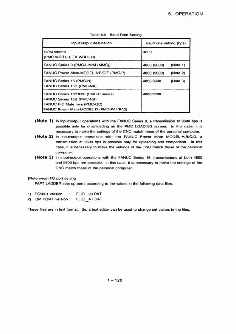
7/25/2019 FAPT Ladder for PC-Operator Manual
http://slidepdf.com/reader/full/fapt-ladder-for-pc-operator-manual 127/302
5. OPERATION
Table 5.6 Baud Rate Setting
Input/output destination
ROM writers
(PMC WRITER, FA WRITER)
Baud rate setting (bps)
4800
FANUC Series 0 (PMC-L/M M (MMC))
FANUC Power Mate-MODEL A/B/C/E (PMC-P)
FANUC Series 15 (PMC-N)
FANUC Series 158 (PMC-NA)
4800 (9600) (Note 1)
4800 (9600)
(Note 2)
480019600
(Note 3)
FANUC Series 16/18 20 (PMC-R series)
FANUC Series 15B (PMC-NB)
FANUC F-D Mate mini (PMC-QC)
FANUC Power Mate-MODEL D (PMCPAl/PA3)
4800/9600
(Note 1)
(Note 2)
(Note 3)
In input/output operations with the FANUC Series 0. a transmission at 9600 bps is
possible only for downloading on the PMC LOADING screen. In this case, it is
necessary to make the settings of the CNC match those of the personal computer.
In input/output operations with the FANUC Power Mate MODEL-A/B/C/D, a
transmission at 9600 bps is possible only for uploading and comparison. In this
case, it is necessary to make the settings of the CNC match those of the personal
computer.
In input/output operations with the FANUC Series 15, transmissions at both 4800
and 9600 bps are possible. In this case, it is necessary to make the settings of the
CNC match those of the personal computer.
[Reference] I 0 port setting
FAPT LADDER sets up ports according to the values in the following data files.
1) PC9801 version :
FLIO 98.DAT
2) IBM PC/AT version :
FLIO-AT.DAT
-
These files are in text format. So, a text editor can be used to change set values in the files.
l-120

7/25/2019 FAPT Ladder for PC-Operator Manual
http://slidepdf.com/reader/full/fapt-ladder-for-pc-operator-manual 128/302
1) Contents of the FLl0_98DAT
(effective data section only)
DATA-BLOCK = IO-PORT-SET
FA-WRITER = RO. 4800. B8, PN. S2, NONE
PMC-WRITER
= RO. 4800, B8, PN. S2, NONE
PMC-L
= RO. 4800, B8, PN. S2. NONE
PMC-M
=RO, 4800, B8, PN. S2, NONE
PMC-M (TT)
= RO, 4800.88, PN. S2, NONE
PMC-M (AXIS)
= RO. 4800.88, PN. S2. NONE
PMC-MMC = RO, 4800, 88. PN. S2. NONE
PMC-MMC (AXIS) = RO. 4800, B8, PN. S2, NONE
PMC-N -RD. 9600,88, PN, S2, NONE
PMC-P - RO, 4800, B8, PN, S2. NONE
PMC-OA - RO, 9600, B8, PN, S2, NONE
PMC-M (I/O)
= RO. 4800, B8, PN, S2, NONE
PMC-M (I/O, TT)
=RO, 4800,88. PN. S2, NONE
PMC-M (l/O, AXIS) = RO. 4800,88, PN, S2, NONE
PMC-N (l/O)
= RO, 9600.88, PN, S2, NONE
PMC-RB
= RO, 9600, B8, PN, S2, NONE
PMC-RC
= RO, 9600, B8, PN, S2, NONE
PMC-RAl = RO, 9600,68, PN, 52, NONE
PMC-RAP
= RO, 9600, 88, PN, S2, NONE
PMC-RBP = RO, 9600, 88. PN. S2, NONE
PMC-RA3 = RO, 9600. 88, PN, S2, NONE
PMC-RB3
= RO, 9600,88, PN, S2, NONE
PMC-RC3 = RO. 9600,88, PN, S2, NONE
PMC-PA1 = RO, 9600.88, PN, S2. NONE
PMC-PA3 = RO, 9600, B8, PN, S2. NONE
PMC-OC
=RO. 9600, B8. PN. S2, NONE
PMC-NB
= RO. 9600, B8, PN, S2, NONE
PMC-RB4 = RO, 9600,88, PN. S2. NONE
PMC-RC4 = RO, 9600, 88, PN. S2. NONE
PMC-RB4 (STEP-SEC)) = Ro, 9600, B8. PN, S2, NONE
PMC-RC4 (STEP-SEO) = RO, 9600,88. PN, S2. NONE
5. OPERATION
2) Contents of the FLIO_AT.DAT
(effective data section only)
DATA-BLOCK = IO-PORT-SET
PM&WRITER
FA-WRITER
PMC-L
PMC-M
PMC-M (-IT)
PMC-M (AXIS)
PMC-MMC
PMC-MMC (AXIS)
PMC-N
PMC-P
PMC-QA
PMC-M (l/O)
PMC-M (I/O, TT)
PMC-M (I/O, AXIS)
PMC-N (l/O)
PMC-RB
PMC-RC
PMC-RAl
PMC-RA2
PMC-RB2
PMC-RA3
PMC-RB3
PMC-RC3
PMC-PA1
PMC-PA3
PMC-QC
PMC-NB
PMC-RB4
PMC-RC4
PMC-RB4 (STEP-SEQ) =COMl : 96, N. 8, 2
PMC-RC4 (STEP-SEQ) =COMl : 96, N, 8.2
=COMl : 48, N. 8.2
=COMl : 48,
N. 8. 2
=COMl : 48,
N. 8. 2
=COM1:48.N,8.2
=COMl : 48,
N, 8.2
=COMl : 48,
N, 8.2
=COMl : 48.
N, 8, 2
=COMI : 48.
N, 8,2
-COMl : 96,
N. 8.2
=COMl : 48,
N, 8,2
=COMl : 96,
N, 8.2
=COMl : 48,
N, 8.2
=COMl : 48.
N, 8,2
=COtVll : 48, N, 8,2
=COMl : 96,
N, 8.2
-COMl : 96,
N, 8, 2
=COMl : 96,
N, 8,2
=COMl : 96,
N, 8.2
=COMl : 96,
N, 8,2
=COMl : 96,
N, 8,2
=COMl : 96.
N, 8,2
=COMl : 96.
N, 8.2
-COMl : 96.
N, 8.2
=COMl : 96,
N, 8.2
=COMl : 96,
N, 8, 2
-COMl : 96,
N. 8, 2
= COMl : 96.
N, 8,2
=COMl : 96,
N, 8.2
=COMl : 96,
N. 8, 2
Entity on the left-hand side of each equal sign ( =) : Device
Entity on the right-hand side of each equal sign (=) : Represented in the format of each
SPEED/MODE command. Only the first parameter (port number) and second parameter (baud
rate) can be changed.
1 - 121

7/25/2019 FAPT Ladder for PC-Operator Manual
http://slidepdf.com/reader/full/fapt-ladder-for-pc-operator-manual 129/302
5. OPERATION
5.6.1 ROM
writers
(PMC
writer,
FA
writer)
ROM format data is written to ROM installed in the PMC. For information on the setting of a
personal computer for I/O operation, see Section 5.6.
ROMs which can be used depend on the
PMC model, as indicated in Table 56.1. When using the FA writer, place it in remote mode.
Table
5. 6. 1
ROMs Usable with Each PMC Model
PMC model Usable ROM
PMC-L/M
256K-bit ROM, 2 each (note 1)
PMC-N
ROM cassette A, B, C, D, and E
PMC-RAl /RA2/RA3/RB
lM-bit ROM
PMCRB2/RB3
lM-bit ROM/ROM module B (note 2)
PMC-RCIRC3
ROM module A, B, C, and D
PMC-QA
ROM cassette A, B
(1)
Read
[Operation]
0 Select [WRT] (writer) on the I/O menu screen.
8 Select [READ].
@ Enter the name of a ROM format file containing read data.
@I Read operation is executed. During operation, the indication “EXECUTING” blinks.
@ When read operation terminates normally, the indication “NORMAL END” is output.
(2) Write
[Operation]
0 Select [WRT] (writer) on the I/O menu screen.
8 Select [WRITE].
8 Enter the name of a ROM format file to be written.
@ Writing is executed. During operation, the indication “EXECUTING” blinks.
6 When writing terminates normally, the indication “NORMAL END” is output.
l-122

7/25/2019 FAPT Ladder for PC-Operator Manual
http://slidepdf.com/reader/full/fapt-ladder-for-pc-operator-manual 130/302
5. OPERATION
(3) Verification
[Operation]
0 Select
[WRT]
(writer) on the I/O menu
screen.
8 Select [VERIFY].
@ Enter the name of a ROM format file to be verified.
@ Verification is executed. During operation, the indication “EXECUTING” blinks.
8 When verification terminates normally, the indication “NORMAL END” is output.
(4)
Blank check
[Operation]
0 Select [WRT] (writer) on the I10 menu screen.
8 Select [BLANK] (blank check).
(3 Enter the name of a ROM format file to check.
@I Blank checking is executed. During operation, the indication “EXECUTING” blinks.
@ When blank checking terminates normally, the indication “NORMAL END” is output.
(5) Termination
[Operation]
0 Select [END].
8 The screen display returns to the main menu screen.
(Note 1) Input/output with ROM for PMC-UM
With PMC-UM, a high ROM is paired with a low ROM. When performing I/O to and
from ROM with an FA writer on a PMC-L/M, FAPT LADDER allows a pair of a high
ROM and low ROM to be processed concurrently. At this time, the < F2 > key can
be used to switch between the processing of a single ROM or the processing of a
pair of ROMs.
1 - 123

7/25/2019 FAPT Ladder for PC-Operator Manual
http://slidepdf.com/reader/full/fapt-ladder-for-pc-operator-manual 131/302
5. OPERATION
1st PAIR
2nd PAIR 3rd PAIR
4th PAIR
0 1 2 3 4 5 6 7
High side Low side
0
q
0clOClcl
PMC-L 0E2
, PMC-M OF2
Socket allocation for concurrent processing of pairs of ROMs with the FA writer
OEl
OF1
Writinq
During concurrent writing, data can be written to a maximum of four pairs of ROMs.
Readina and verification
During concurrent reading or verification, only one pair of ROMs can be handled at a time.
When two or more pairs are set, the ROMs with the smallest socket number are read or
verified.
(Note 2) When writing 1Mbit ROM for PMC-RB2 with FA writer, “ID ERROR” will be
displayed on FA writer. But writing terminates normally.
(Note 3) PMC-P, PA1IPA3, NB, QC do not transfer data to and from EPROM. (EPROM
cannot be installed in PMC-P, PAlIPA3, NB, QC.)
5.6.2
Transfer to and from PMC-L/M (FANUC Series 0)
Data can be transferrod to and from PMC-L/M. See Section 5.6 for the setting of the personal
PMC loading screen
+I I/O (P-G) screen 1
I I
- FAPT LADDER 1 )- FSO
Switchable between 4800 bps and 9600 bps
Parameter No. 0060
11Download IL
I
4800
bps (fixed)
(Note)
II
Upload Ib
4800 bps (fixed)
(Note)
4800 bps (fixed)
(Note)
I I
FSO baud rate settinq
4 PO (P-G) screen 1
I
1
computer for I/O operz.:lon.
(Note) A ladder editing cassette is required for this operation.
1-124

7/25/2019 FAPT Ladder for PC-Operator Manual
http://slidepdf.com/reader/full/fapt-ladder-for-pc-operator-manual 132/302
5. OPERATION
SYSTEM P-MODEL G
PHC LOADING
READ OR WRITE OR VERIFY
ADDRESS :
OOOOH
EXECUTING
DATA
:
OOH
i
1 [CANCEL] [ 11 II 1
Fig. 5.6.2 (a) PMC Load Screen
Fig. 5.6.2 (b) l/O (P-G) Screen
(1) FSO baud rate setting
This setting functions only for download operation using the PMC load screen.
[Operation]
*O Press < DGNOSPARAM > to display the parameter screen.
*Q A baud rate can be set by specifying the parameter as follows:
bit 7
bit 6 bit 5
bit 4 bit 3
bit 2
bit 1
bit 0
0060
PCLDB
PCLDB 0 : 4800 bps
1 : 9600 bps
*a After a parameter change, turn the power off then on again.
(2) Download
(a) Download (using the PMC load screen)
[Operation]
0 Select [PMC] on the l/O menu screen.
8 Select (DNLOAD] (download) on the PMC menu screen.
@ Enter a ROM format file name.
*@ Press c 1> on the PMC load select screen of the CNC.
(Select (1) LOAD FROM I/O. The screen shown in Fig. 5.6.2(a) appears.)
Position the cursor on LOAD for the output route on the PMC menu screen, then press
the <RETURN> key.
Downloading is executed. During operation, the indication “EXECUTING” blinks.
When downloading terminates normally, the indication “NORMAL END” is output.
1-125

7/25/2019 FAPT Ladder for PC-Operator Manual
http://slidepdf.com/reader/full/fapt-ladder-for-pc-operator-manual 133/302
5. OPERATION
(b) Download (operation using the l/O (P-G) screen)
[Operation]
@Select [PMC] on the I/O menu screen.
8 Select [DNLOADJ (download) on the PMC menu screen.
8 Enter a ROM format file name.
*@ Press < 5 > on the PMC load select screen of the CNC.
(Select (5) EDIT LADDER.)
*@ Press the CNC soft keys [l/O] and [P-G] in this order. (The screen shown in Fig.
5.6.2(b) appears.)
451 Position the cursor on EDIT for the output route on the PMC menu screen, then press
the <RETURN> key.
@ Download operation is executed. During operation, the indication
“EXECUTING”
blinks.
@I When downloading terminates normally, the indication “NORMAL END” is output.
(Note)
During downloading to PMC-L/M, symbol and comment data is not transferred.
(3) Upload
[Operation]
0 Select [PMC] on the I/O menu screen.
@ Select [UPLOAD] on the PMC menu screen.
*a Press <5> on the PMC load select screen of the CNC.
(Select (5) EDIT LADDER.)
*@ Press the CNC soft keys [VO] and [P-G] in this order. (The screen shown in Fig. 5.6.2(b)
appears.)
@ Enter a ROM format file name.
@ Uploading is executed. During operation, the indication “EXECUTING” blinks.
Q When uploading terminates normally, the indication “NORMAL END” is output.
l-126

7/25/2019 FAPT Ladder for PC-Operator Manual
http://slidepdf.com/reader/full/fapt-ladder-for-pc-operator-manual 134/302
5. OPERATION
(4) Comparison
[Operation ]
@ Select [PMC] on the I/O menu screen.
0 Select [COMPAR] (comparison) on the PMC menu screen.
43 Press <5> on the PMC load select screen of the CNC.
(Select (5) EDIT LADDER.)
*@I Press the CNC soft keys [I/O] and [P-G] in this order. (The screen shown in Fig. 5.6.2(b)
appears.)
6 Enter a ROM format file name.
@ Comparison is executed. During operation, the indication “EXECUTING” blinks.
B When comparison terminates normally, the indication “NORMAL
END”
is output.
(5) Termination
[Operation]
0 Select [END].
C3 The screen display returns to the main menu screen.
(Note) In the operations above, an asterisk prefixed to a circled number represents an operation
on the CNC.
l-127

7/25/2019 FAPT Ladder for PC-Operator Manual
http://slidepdf.com/reader/full/fapt-ladder-for-pc-operator-manual 135/302
5. OPERATION
5.6.3 Transfer to and from PMC-P (FANUC Power Mate-MODEL A/B/C/E)
Data can be transferred to and from PMC-P. See Section 5.6 for the setting of the personal
computer for 1’0 operation.
To transfer data to and from PMC-P, some parameters need to be set
on the Power Mate. Set the parameters according to Item (1) below.
- FAPT LADDER
1 Download //
1 Upload 1
11 Comparison It
4800 bps (fixed)
I
1
Switchable between 4800 bps and 9600 bps
Parameter Nos. &0226 or &0227
Switchable between 4800 bps and 9600 bps
Parameter Nos. &0226 or &0227
(1) Power Mate-MODEL
A/B/C/E setting
L
Power Mate-MODEL A’BIC’E baud rate setting
. Power Mate-MODEL _
A/B/C/E
PMC loading
screen
J Diagnostic screen 1
4 Diagnostic screen 1
PMC-P needs to be made ready for 110 operation. The operation below is required on the Power
Mate.
[Operation ]
$0 Press < DGNOSPARAM > to display the parameter screen.
*a Position the cursor on the I 0 parameter, then press < 0 > < INPUT > or < 1 > <INPUT > .
(Specify 0 or 1 in the I 0 parameter setting.)
*O Set the parameters as follows:
When I 0 parameter settinq = 0
bit 7 bit 6 bit 5 bit 4 bit 3
bit 2 bit 1 bit 0
&0006
&0009
&0014
&0226
I-I-I-I-I-I-lOIll
I
1 _ _ - -
0 - 1
I
I
0 _ - _ - - - -
I I I I I
I I I
I
BRATEO
I
BRATEO 1 0: 4800 bps
1 1 : 9600 bps
1-128
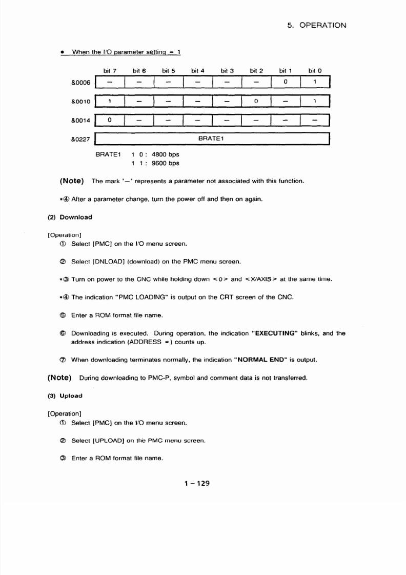
7/25/2019 FAPT Ladder for PC-Operator Manual
http://slidepdf.com/reader/full/fapt-ladder-for-pc-operator-manual 136/302
5. OPERATION
When the I/O parameter settino = 1
II0006
a0010
&0014
8~0227
bit 7 bit 6 bit 5 bit 4 bit 3 bit 2 bit 1 bit 0
I
BRATEl
BRATEl 1 0: 4800 bps
1 1 : 9600 bps
(Note) The mark ‘-’
represents a parameter not associated with this function.
*@ After a parameter change, turn the power off and then on again.
(2) Download
[Operation]
0 Select [PMC] on the I 0 menu screen.
8 Select [DNLOAD] (download) on the PMC menu screen.
*@ Turn on power to the CNC while holding down < 0 > and <X/AXIS > at the same time.
*@ The indication “PMC LOADING” is output on the CRT screen of the CNC.
@ Enter a ROM format file name.
8 Downloading is executed.
During operation, the indication “EXECUTING” blinks, and the
address indication (ADDRESS =) counts up.
@ When downloading terminates normally, the indication “NORMAL END” is output.
(Note)
During downloading to PMC-P, symbol and comment data is not transferred.
(3) Upload
[Operation]
Select [PMC] on the I 0 menu screen.
Select [UPLOAD] on the PMC menu screen.
Enter a ROM format file name.
l-129

7/25/2019 FAPT Ladder for PC-Operator Manual
http://slidepdf.com/reader/full/fapt-ladder-for-pc-operator-manual 137/302
5. OPERATION
@I The indication “PLEASE SET UP PMC” is output.
*8 Turn on power to the CNC, then press < DGNOSIPARAM > twice to display the diagnostic
screen.
*@3 Press <NO. > on the CNC, then press <WRITE> while holding down < * >.
(?I Uploading is executed.
During operation, the indication “EXECUTING” blinks, and the
address indication (ADDRESS =) counts up. On the CNC, the indication “WRITE” blinks.
@ When uploading terminates normally, the indication “NORMAL END” is output. On the
CNC, the indication “WRITE” disappears.
(4) Comparison
[Operation]
0 Select ]PMC) on the I/O menu screen.
8 Select [COMPARJ (comparison) on the PMC menu screen.
@ Enter a ROM format file name.
@I The indication “PLEASE SET UP PMC” is output.
*@ Turn on power to the CNC, then press < DGNOSPARAM > twice to display the diagnostic
screen.
*Q Press <NO. > on the CNC, then press C WRITE> while holding down < ’ >-
8 Comparison is executed.
During operation, the indication “EXECUTING” blinks, and the
address indication (ADDRESS =) counts up. On the CNC, the indication “WRITE” blinks.
@I When comparison terminates normally, the indication “NORMAL END” is output. On the
CNC, the indication “WRITE” disappears.
(5) Termination
[Operation]
0 Select [END].
8 The screen display returns to the main menu screen.
(Note) In the operations above, an asterisk prefixed to a circled number represents an operation
on the CNC.
l-130

7/25/2019 FAPT Ladder for PC-Operator Manual
http://slidepdf.com/reader/full/fapt-ladder-for-pc-operator-manual 138/302
5. OPERATION
5.6.4 Transfer to and from PMC-N/NA (FANUC Series 15MODEL A,
-MODEL B)
Data can be transferred to and from PMC-N. See Section 5.6 for the setting of the personal
computer for I/O operation. To transfer data to and from PMC-N, FS15 baud rate setting is
required. See Item (1) below.
- FAPT LADDER -
1 Download b
II
Upload Ib
1 Comparison b
Switchable between 4800 bps and 9600 bps
[DATA TRANSFER RATE (OFF-LINE)]
Switchable between 4800 bps and 9600 bps
fDATA TRANSFER RATE (OFF-LINE)1
Switchable between 4800 bps and 9600 bps
[DATA TRANSFER RATE (OFF-LINE)]
FS15 baud rate settinq
FS15
Title screen
I
I/O screen
I
j110[
(1) FS15 baud rate setting
FS15 baud rate setting is required. On the FSl5, data can be transferred at either 9600 bps or
4800 bps. The baud rate setting on the personal computer needs to match the baud rate setting
on the FS15. Operation on the FS15 is described below.
[Operation]
*@ Press the < CNCIPMC > key.
*8 Press the soft keys [PCPRM] and [MODE] in this order.
*@ The following information is output on the CRT screen of the CNC:
PMC MODE
PMC DATA INITXALIZE
O
ON
DATA TRANSFER RATE (OFF-LINE)
9600BPS 4800BPS
DATA TRANSFER TO RAMBOARD MANUAL AUTO
RAM ENABLE (PC DGN,EDIT)
O
ON
DATA TRANSFER RATE (AUX)
4800BPS 9600BPS
*@ Press the values of both DATA TRANSFER RATE (OFF-LINE) and DATA TRANSFER
RATE (AUX) by moving the cursor and using soft keys.
1 - 131
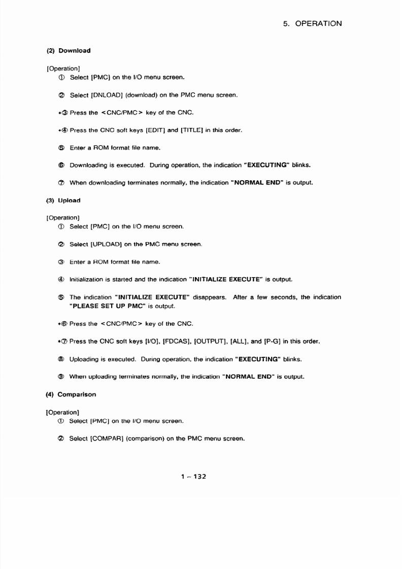
7/25/2019 FAPT Ladder for PC-Operator Manual
http://slidepdf.com/reader/full/fapt-ladder-for-pc-operator-manual 139/302
5. OPERATION
(2) Download
[Operation]
@ Select [PMC] on the l/O menu screen.
8 Select [DNLOAD] (download) on the PMC menu screen.
*$ Press the <CNC/PMC> key of the CNC.
*@I Press the CNC soft keys [EDIT] and [TITLE] in this order.
61 Enter a ROM format file name.
@ Downloading is executed. During operation, the indication “EXECUTING” blinks.
B When downloading terminates normally, the indication “NORMAL END” is output.
(3) Upload
[Operation]
0 Select [PMC] on the I/O menu screen.
8 Select [UPLOAD] on the PMC menu screen.
@ Enter a ROM format file name.
@I Initialization is started and the indication “INITIALIZE EXECUTE” is output.
61 The indication “INITIALIZE EXECUTE” disappears.
After a few seconds, the indication
“PLEASE SET UP PMC” is output.
*@ Press the <CNC PMC> key of the CNC.
*8 Press the CNC soft keys [l/O], [FDCAS), [OUTPUT], [ALL], and [P-G] in this order.
@I Uploading is executed. During operation, the indication “EXECUTING” blinks.
@I When uploading terminates normally, the indication “NORMAL END” is output.
(4) Comparison
IOperation]
0 Select [PMC] on the I/O menu screen.
8 Select [COMPAR] (comparison) on the PMC menu screen.
1-132

7/25/2019 FAPT Ladder for PC-Operator Manual
http://slidepdf.com/reader/full/fapt-ladder-for-pc-operator-manual 140/302
5. OPERATION
0 Enter a ROM format file name.
@ Initialization is started and the indication “INITIALIZE EXECUTE” is output.
0 The indication “INITIALIZE EXECUTE” disappears.
After a few seconds, the indication
“PLEASE SET UP PMC” is output.
* I3 Press the < CNC’PMC > key of the CNC.
*@ Press the CNC soft keys [l/O], [FDCAS], [OUTPUT], [ALL], and [P-G] in this order.
@ Comparison iS executed. During operation, the indication “EXECIJTING” blinks.
@I When comparison terminates normally, the indication “NORMAL END” is output.
(5) Termination
[Operation]
0 Select [END].
8 The screen display returns to the main menu screen.
(Note 1) In the operations above,
an asterisk prefixed to a circled number represents an
operation on the CNC.
(Note 2) For FS15, it is possible UPLOAD, COMPARISON PMC program without PASCAL, C
LANGUAGE data.
In this case, please change (3 of each function as below.
*@I Press the CNC soft keys [l/O], [FDCAS], [OUTPUT], [LADDER], and [P-G] in
this order.
1-133

7/25/2019 FAPT Ladder for PC-Operator Manual
http://slidepdf.com/reader/full/fapt-ladder-for-pc-operator-manual 141/302
5. OPERATION
5.6.5 Input/Output for PMC-QA (FANUC SYSTEM F-MODEL D Mate)
Before PMC-CA and the ladder program are transmitted, the following (1) or (2) must be
performed.
Whether (1) or (2) is depended on the model of FD Mate.
(1) Setting of FD Mate PMC communicative utility FLEX OS version
(a) File configuration
The configuration of files in the floppy disk is as follows:
C
DRIVERS
--c
ACILOAD. BAT (Driver installation batch file)
FDM_SCD. DRV
UTILS
1
FDUTILS. 286 (Utility start file)
PGFD. 286
PGSV. 286
FDSV. 286
(b) Installing the driver
The driver must be installed only once when power to the main unit is turned on. After the
operating system starts, insert the floppy disk of external equipment input/output software
into drive A in the following example and enter the following commands.
To change drives
To change directories
To install the driver A : DRIVERS > ACILOAD r Return J
FD Mate Main unit
6 : >A-rReturnJ
A
A:>
A : >CD DRIVERS r Return J
A : DRIVERS/>
Note 1)
The underlined portions indicate data entered from the keyboard. J
indicates soft key entry. Other portions are displayed by the system. Key entries
are not case sensitive. The following explanations are given in this format.
Note 2) Incorporate the RS-232-C serial driver into memory with a logical name (ser:).
(The system needs to be changed so that the serial drive is loaded with ser: when
the operating system is started.)
The following define statement must be entered from the keyboard according to the
driver version after the driver is installed.
define -s fanuc_ser = ON
In the above example, enter the following from the keyboard:
B: DRIVERS > define -s fanuc ser = ON
1-134
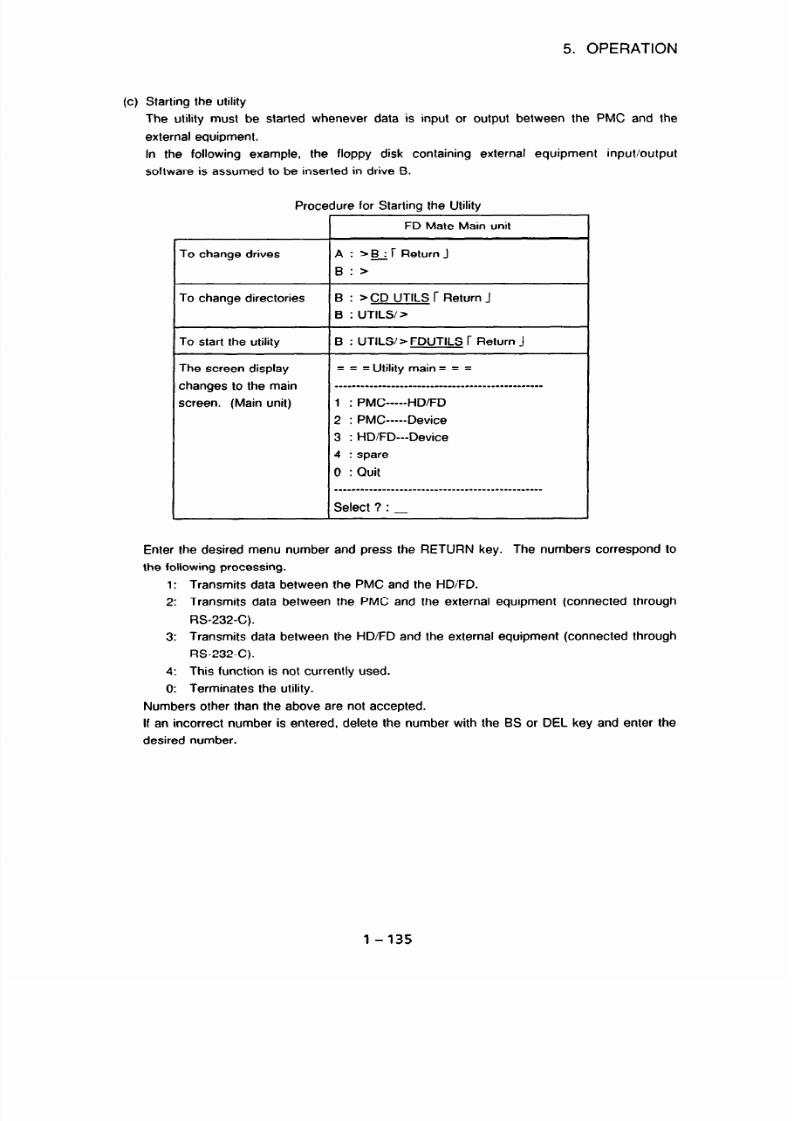
7/25/2019 FAPT Ladder for PC-Operator Manual
http://slidepdf.com/reader/full/fapt-ladder-for-pc-operator-manual 142/302
5. OPERATION
Starting the utility
The utility must be started whenever data is input or output between the PMC and the
external equipment.
In the following example, the floppy disk containing external equipment input/output
software is assumed to be inserted in drive B.
To change drives
To change directories
To start the utility
The screen display
changes to the main
screen. (Main unit)
Procedure for Starting the Utility
FD Mate Main unit
A : >B *r ReturnJ
B:>
B : > CD UTILS I- Return J
B : UTILS/>
B : UTILS > FDUTILS r Return J
Utility main = = =
____----___-______-_____________________----
1 : PMC-----HO/F0
2 : PMC-----Device
3 : HDIFD---Device
4 : spare
0 : Quit
Enter the desired menu number and press the RETURN key. The numbers correspond to
the following processing.
1:
Transmits data between the PMC and the HDI’FD.
2: Transmits data between the PMC and the external equipment (connected through
RS-232-C).
3: Transmits data between the HDiFD and the external equipment (connected through
RS-232-C).
4:
This function is not currently used.
0: Terminates the utility.
Numbers other than the above are not accepted.
If an incorrect number is entered, delete the number with the BS or DEL key and enter the
desired number.
1 - 13s

7/25/2019 FAPT Ladder for PC-Operator Manual
http://slidepdf.com/reader/full/fapt-ladder-for-pc-operator-manual 143/302
5. OPERATION
(2) Setting the UNIX version of the F-D Mate PMC communication utilities
(a) File configuration
The configuration of utility files on the distribution floppy disk is as shown below.
UTILS
F
FDUTILS (utility startup file)
FDSV
PGFD
PGSV
(b) Driver installation and utility startup
Operation on the Main screen
(1) Create an appropriate directory on the # mkdir directorv-name
hard disk.
r Return J
(2) Make the directory created in step (1)
# cd directorv-name r Return J
current.
(3) Copy the utility software on the floppy
# doscD A:IUTILS/FDUTILS . r Return J
disk (drive A) to the current directory.
# doscD A:/UTILS/FDSV
r
Return J
# doscp AYUTILS’PGFD .
r Return J
# dosco AYUTILWPGSV .
r Return J
(4) Make the copied files executable. # chmod +x * r Return J
(5) Specify a path.
# PATH = $PATH:.;export PATH
r Return J
(6) Start a utility. (Note)
# FDUTILS r Return J
(Note)
The method of using the UNIX version differs from that of the Flex version in the
following two points.
1. Filenames must be in lowercase letters.
2. ACILOAD is unnecessary.
1-136
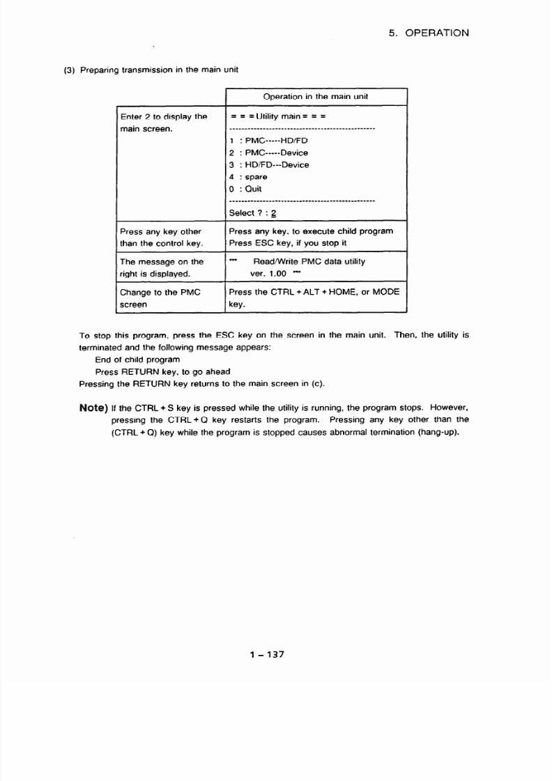
7/25/2019 FAPT Ladder for PC-Operator Manual
http://slidepdf.com/reader/full/fapt-ladder-for-pc-operator-manual 144/302
(3) Preparing transmission in the main unit
5. OPERATION
Enter 2 to display the
main screen.
Press any key other
than the control key.
The message on the
Vight is displayed.
Change to the PMC
screen
1
peration in the main unit
===
Utility main = = =
-----------------------------------------.------
1 : PMC
-----HO/F0
2 : PMC-----Device
3 : HDIFD---Device
4 : spare
0 : Quit
------------------------------------------------
Select 3 : 2
Press any key, to execute child program
Press ESC key, if you stop it
Read/Write PMC data utility
ver. 1.00 -
Press the CTRL + ALT + HOME, or MODE
key.
To stop this program, press the ESC key on the screen in the main unit. Then, the utility is
terminated and the following message appears:
End of child program
Press RETURN key, to go ahead
Pressing the RETURN key returns to the main screen in (c).
Note) If the CTRL + S key is pressed while the utility is running, the program stops. However,
pressing the CTRL+Q key restarts the program.
Pressing any key other than the
(CTRL + Q) key while the program is stopped causes abnormal termination (hang-up).
l-137

7/25/2019 FAPT Ladder for PC-Operator Manual
http://slidepdf.com/reader/full/fapt-ladder-for-pc-operator-manual 145/302
5. OPERATION
(4) Down load
To start the utility
in the main unit of
F-D Mate
To put the
personal
computer in the
reception wait
status
To output
sequence data
from the PMC
4t transmission
Operation in the personal compu
@I Select [PMCJ from the
input/output menu screen.
@ Select [DNLOAD] (download)
from the PMC menu screen.
aEnter the name of the ROM
format file.
a Initialization begins, and the
message “INITIALIZE EXECUT
appears.
The screen display changes, and
“PMC SIDE SET I/O DISPLAY, At
KEY IN FILE NAME.” is displayed
The EXECUTING turns on and off
and the counter is displayed at tht
bottom of the screen.
Operation in the F-D Mate main
unit:PMC
3 Start the utility. (See Subset.
3.4.1.)
3 Select PMC - Device.
Select 7 : 2
D Press MODE key or press
CTRL + ALT + HOME key to
display the PMC screen.
D Press the IO key to display the IO
screen.
3 Press the FDCAS key to display
the FDCAS screen.
D Press the OUTPUT key to select
OUTPUT.
0, Press the LADDER key to select
LADDER.
YpPress the P-G key to select P-G.
The displayed value indicating an
address is counted.
If transmission terminates normally, the personal computer displays “NORMAL END” and the
PMC displays OUTPUT COMPLETED.
1-138

7/25/2019 FAPT Ladder for PC-Operator Manual
http://slidepdf.com/reader/full/fapt-ladder-for-pc-operator-manual 146/302
5. OPERATION
(5) Upload
To start the utility
in the main unit of
F-D Mate
To put PMC in
the reception wait
status
To output
sequence data
from the personal
computer
At transmission
Operation in the P-G Mate
@ Select [PMC] from the
input/output menu screen.
0 Select [UPLOAD] (upload) from
the PMC menu screen.
@Enter the name of the ROM
format file.
@Initialization begins, and the
message “INITIALIZE EXECUTE”
appears.
The EXECUTING turns on and off,
and the counter is displayed at the
bottom of the screen.
Operation in the F-D Mate main
unit/PMC
3 Start the utility. (See (3))
3 Select PMC - Device.
Select ? : 2
3 Press the MODE key or
CTRL + ALT + HOME key to
display the PMC screen.
9 Press the EDIT key to display the
EDIT screen.
9 Press the TITLE key to display the
TITLE screen.
The displayed value indicating a size
s counted.
If transmission terminates normally, the personal computer displays “NORMAL END” and the
PMC displays INPUT COMPLETED.
1-139

7/25/2019 FAPT Ladder for PC-Operator Manual
http://slidepdf.com/reader/full/fapt-ladder-for-pc-operator-manual 147/302
5. OPERATION
5.6.6 Transfer to and from PMC-R series/PAl/PA3/NB/QC
Data can be transferred serially via RS-232-C. In this case, personal computer port must be set.
See Section 5.6 for the setting of the personal computer for I/O operation.
- FAPT LADDER 1
1 Download f
II
Upload Ik
II Comparison II-
9600 bps14800 bps
9600 bps14800 bps
FS16/18/15B
-Power Mate-D, -
F-D Mate mini
w-1
PMC (I/O) screen
9600 bps/4800 bps
PMC (I/O) screen
Baud rate settina for FSl6/18/15B, Power Mate-D, and F-D Mate mini
(1) Download
[Operation]
0 Select [PMC] on the I/O menu screen.
8 Select [DNLOAD] (download) on the PMC menu screen.
$8 Press the <SYSTEM > key of the CNC.
*@ Press the CNC soft keys [PMC], [l/O], [HOST], and [EXEC] in this order.
0 Enter a ROM format file name.
@ Downloading is executed. During operation, the indication “EXECUTING” blinks.
8 When downloading terminates normally, the indication “NORMAL END” is output.
(2) Upload
If the PMCRCRC3, -CC, or -NB is used, language data (C language) other than Ladder
programs can be used. When uploading or comparison is executed from one of these PMCs,
one of two data types (LADDER or ALL) can be specified. LADDER and ALL have the
following meanings:
LADDER Sequence program only
ALL
Sequence program and language data (C language)
l-140

7/25/2019 FAPT Ladder for PC-Operator Manual
http://slidepdf.com/reader/full/fapt-ladder-for-pc-operator-manual 148/302
5. OPERATION
Specify either data type in step 8 of the operation described below:
[Operation]
0 Select [PMC] on the I/O menu screen.
8 Select [UPLOAD] on the PMC menu screen.
*a Press the <SYSTEM> key of the CNC.
*@ Press the CNC soft keys [PMC], (IO], [HOST], and [EXEC] in this order.
@ Enter a ROM format file name.
@ Select either LADDER or ALL with cursor.
(?I Uploading is executed. During operation, the indication
“EXECUTING” blinks.
@ When uploading terminates normally, the indication
“NORMAL END” is
output.
(3) Comparison
[Operation]
0 Select [PMC] on the 11’0menu screen.
C 9 Select [COMPAR] (comparison) on the PMC menu screen.
*a Press the <SYSTEM > key of the CNC.
*@I Press the CNC soft keys [PMC], [I/O], [HOST], and [EXEC]
in this order.
@ Enter a ROM format file name.
6) Comparison is executed. During operation, the indication
“EXECUTING”
blinks.
8 When comparison terminates normally, the indication
“NORMAL END”
is output.
(4) Termination
[Operation]
0 Select [END].
(21 The screen display returns to the main menu screen.
(Note) In the operations above, an asterisk prefixed to a circled number represents an operation
on the CNC.
l- 141

7/25/2019 FAPT Ladder for PC-Operator Manual
http://slidepdf.com/reader/full/fapt-ladder-for-pc-operator-manual 149/302
5. OPERATION
(5)
CRT/MD1 and DPUMDI of the Power Mate-D
The NC of the Power Mate-D has the CRT/MD1 screen and the DPUMDI screen. When the
CRTlMDl screen is used, the procedures for data input/output are the same as those with the
PMC-R Series ((1) to (4) above). When the DPUMDI screen is used, the procedures for data
input/output are different from those with the PMC-R Series.
When the DPL/MDI screen is used, perform downloading, uploading, and comparison as
described below:
(a)
Press the < DGNOS > key on the DPUMDI screen and select the diagnostic data screen.
03
Press the c READ> or c WRITE> key on the DPUMDI screen.
w
Follow procedures (1) to (4) described above on the personal computer.
5.6.7
Memory card interface in the personal computer and memory card
A ROM format file compiled in a personal computer can be converted to a memory card format file,
and output to a memory card via a memory card interface installed in the personal computer. The
PMC program on the memory card can be sent to the RAM of the CNC by inserting the memory
card in the memory card interface in the CNC.
By reversing the procedure, programs can be
transferred from the CNC RAM to the memory card.
5.6.7.1
PMC program transfer from the personal computer to the CNC
[Operation]
Install a memory card interface in the personal computer.
Compile a source program to create a ROM format file.
Return to the main menu, and select [l/O] (input/output) from
it.
Select [M-CARD] (memory card) from the input/output menu.
F4 KEY : Handy Fle
F5 KEY : Memory card
Fig. 5.6.7.1 (a) InputiOutput Menu
1-142

7/25/2019 FAPT Ladder for PC-Operator Manual
http://slidepdf.com/reader/full/fapt-ladder-for-pc-operator-manual 150/302
5. OPERATION
@
Select
[WRITE]
(write (programmer -> memory card)).
Fig. 5.6.7.1 (b) Memory Card Input/Output Screen
@ Convert the file from ROM format to memory card format.
Specify the following items for execution.
Name of the ROM format file
Specify the ROM format file to be converted.
Name of the memory card file
Specify the name of a memory card file (accessible via a memory card interface in the
CNC) to be created by conversion, and the drive where the memory card is inserted.
l /O i TO UC ::
&BP
WRTE (PROCRAWR - > Memory Card
ROM FORMAT FLE NAME
: AYDATAAYSAMFLE llEX
Memory Card FLE NAME
: DYSAMPLE XBF
(Specfy the MEMORY CARD drive)
Fig. 5.6.7.1 (c) InputlOutput (to MC) Screen
The following operations are performed on the CNC side.
l-143

7/25/2019 FAPT Ladder for PC-Operator Manual
http://slidepdf.com/reader/full/fapt-ladder-for-pc-operator-manual 151/302
5. OPERATION
0 The following two methods can be used to insert the memory card output in step @ into
the
memory card interface in the CNC and read programs on the memory card.
0
Using the I/O function of the PMC
Specify M-CARD, READ, and the desired filename or file number at DEVICE,
FUNCTION, and FILE NO. on the PMC l/O screen, respectively. “7en press soft key
[EXECJ. Sequence programs are read from the memory card file created in step 0.
PMC 110 screen
PMCI/O
PROGRAM
CHANNEL = 1
DEVICE
= M-CARD
~;~~J..~~~Ij-j~;~ READ
DATA KIND = LADDER
FILE NO.
q
( #NAME )
MONIT STOP
I
EXEC I [CANCEL]WRITE I[ READ [COMPARI
Using the BOOT SYSTEM at power-on time
See Appendix 5.
5.6.7.2
PMC program transfer from the CNC to the personal computer
PMC programs are written to a memory card, using a memory card interface in the CNC. When
the memory card is inserted in a memory card interface in the personal computer, the PMC
programs on the memory card can be accessed as ordinary MS-DOS files.
[Operation]
0 Specify M-CARD, WRITE, DATA KIND, and the desired filename (omissible) at DEVICE,
FUNCTION, LADDER, and FILE NO. on the PMC I/O screen, respectively, then press soft
key [EXEC]. Sequence programs are output to the memory.
l-144

7/25/2019 FAPT Ladder for PC-Operator Manual
http://slidepdf.com/reader/full/fapt-ladder-for-pc-operator-manual 152/302
5. OPERATION
PMC I/O screen
' PMC I / O
PROGRAM MONIT STOP-
CHANNEL = 1
DEVICE
= M-CARD
;;i~iJJ ~;I;$&&= WRITE
DATA
KI ND = LADDER
FI LE NO. =
( #NAME )
[ .EXEC
1[CANCEL
[WRI TE
1 E
READ
1 [COMPARI
The fol l ow ngperati ons re performed on thepersonal computer side.
Install a memory card interface in the personal computer.
Select
Select
Select
[l/O] (input/output) from the main menu.
[M-CARD] (memory card) from the input/output menu. (See Fig.
5. 6. 7. 1
a).)
[READ]
(read (programmer C- memory card)). (See Fig. 5.6.7.1 (b).)
Convert the PMC programs output to a memory card in step @ from memory card format
to ROM format by specifying the following items and running the utility.
Name of the memory card file
Specify the name of the conversion source memory card file written to the memory
card, and the memory card drive in which the memory card is inserted.
Name of the ROM format file
Specify the filename to be assigned to the ROM format data after
1.~3C
FROM K )
~~~~~~~~~~~~~~~~~~~~~~~~~~~
READ (PROCRAMER - > Memory Card
Memory Card FLE NAME :
DYSAMFLE #RF
(Specfy the MEMORY CARD drive)
R& FORMAT FLE NAME
:
AYDATAYSMPE #EX
Fig. 5.6.7.2 (a) Input/Output (from MC) Screen
conversion.
1 -
145

7/25/2019 FAPT Ladder for PC-Operator Manual
http://slidepdf.com/reader/full/fapt-ladder-for-pc-operator-manual 153/302
5. OPERATION
0 Discompile the ROM format file after conversion, and the resultant file will become able to
be edited on the personal computer.
5.6.7.3
Memory card input/output function (PMC-RAl) for the PMC of the
CNC (L/R) with loader control
This function writes a loader control sequence program to, or reads it from, the FANUC Series 16-
MODEL B with loader control. The loader control sequence program can be edited by specifying
the model as PMC-RAl.
(1)
Writing (programmer - > memory card)
To write an L/R sequence program to a memory card, use the F8 key (L/R).
(The operations other than input/output with the memory card (such as editing) are the same
as those for the conventional PMC-RAl.)
[Operation]
(2)
Install a memory card interface in the personal computer.
Select [INOUT] (input output) from the main menu.
Select [M-CARD] (memory card) from the input/output menu.
Specify the names of the desired ROM format file and memory card file. (The memory
card filename is specified in the form of memory card drive + filename.)
Write to the memory card using the F8 key (L/R).
WRTE fPROCRME% - > Memory Card
ROM FORMAT FLE NAME
:
AYDATAYSMPLE XEX
Memory Card FLE NAME
:
DYSAMPLE XBF
(Specfy the MEWRY CARD drive)
Fig. 5.6.7.3 Input/Output (to MC) Screen (model supporting loader control)
Reading (programmer < - memory card)
To read the loader control sequence program from the memory card, use the same operating
procedure as for the conventional PMC-RAl.
1-146

7/25/2019 FAPT Ladder for PC-Operator Manual
http://slidepdf.com/reader/full/fapt-ladder-for-pc-operator-manual 154/302
5. OPERATION
56.8 Handy File + 3.5” floppy disk (MS-DOS format)
If a ROM format file compiled on a personal computer is converted to Handy File format and output
to a 3.6” floppy disk (MS-DOS format), the PMC program can be read into the RAM of the CNC
via a Handy File interface connected to the CNC. This operation can be reversed.
5.6.8.1
PMC program transfer from the personal computer to
the CNC
[Operation]
Compile a source program, and create a ROM format file.
Select [l/O] (input/output) from the main menu.
Select [FDCAS] (FLOPPY CASSETTE ADAPTER & Handy File) from
menu. (See Fig. 5.6.7.1 (a).)
the input/output
Select [WRITE] (write (programmer -> FLOPPY CASSETTE ADAPTER & Handy File)).
IKI iFDCASi
&B
\\\m-
Fl
KEY : WRTE (PAOCRAhSA --> Handy Fle)
F2 KEY : READ (PROCRMMR <- Handy Fle)
FO KEY
:
ESD
Fig. 5.6.8.1 (a) FDCAS Input/Output Screen
Convert the ROM format file to Handy File format by specifying the following items and
running the utility.
Name of the ROM format file
Specify the name of the ROM format file to be converted.
Name of the Handy File format file
Specify the name to be assigned to the Handy File format file (accessible by the Handy
File) to be generated by conversion, and the 3.5” disk drive to which the file is output;
5” floppy disk cannot be used.
l - 147

7/25/2019 FAPT Ladder for PC-Operator Manual
http://slidepdf.com/reader/full/fapt-ladder-for-pc-operator-manual 155/302
5. OPERATION
' ARI TE PROCRAMER - > HandyFi l e:
Fi M( ORMT FI LE t&ME
:
A: YDATACSAAl NE. PEX
HandyFi l e FI LE i AME
: C: YSAl l F ' LE. : SF
: Speci f he f l oppydi sk dr i ve
The following operations are performed on the CNC side.
@ Connect the CNC and Handy File, and insert the 3.5” floppy disk generated in step @ into
the Handy File.
5.6.8.2 PMC program transfer from the CNC to the personal computer
[Operation]
Connect the CNC and Handy File, and output the PMC program to a 3.5” floppy disk (MS-
DOS format).
The following operations are performed on the personal computer side.
Select [l/O] (input/output) from the main unit.
Select [FDCAS] (FLOPPY CASSETTE ADAPTER & Handy
menu.
Select [READ] (read (programmer <- FLOPPY CASSETTE
(See Fig. 5. 6. 7. 1(a).)
File) from the input/output
ADAPTER & Handy File)).
Convert the PMC program on a 3.5” floppy disk (Handy File format) generated in step 0 to
ROM format by specifying the following items and running the utility.
Name of the Handy File format file
Specify the program name output in step 0, and the 3.5” floppy disk drive where the
floppy disk is inserted.
Name of the ROM format file
Specify the filename to be assigned to the ROM format data generated by conversion.
1-148

7/25/2019 FAPT Ladder for PC-Operator Manual
http://slidepdf.com/reader/full/fapt-ladder-for-pc-operator-manual 156/302
5. OPERATION
5.6.9
I. 0 ; FROM FDCAS i
:::wc-Rc3 _\\ 1 ~,@ux%wm
.: ‘~_ \\\,\...._ 1
READ (PROCRAWR < Handy Fle
Handy Fle FLE WAME
: CYSAWLE :SF
(Specfy the floppy dsk drive
ROM FORUAT FLE NAUE
: AYDATAYSAWLE PEX
Fig. 5.6.8.2 (a) Input/Output (from FDCAS) Screen
Discompile the ROM format file after conversion, and the resultant file will become able to
be edited on the personal computer.
FLOPPY CASSETTE ADAPTER + 3.5” floppy disk (P-G format)
If a ROM format file compiled on a personal computer is converted to Handy File format and output
to a 3.6” floppy disk (P-G format), the PMC program can be read into the RAM of the CNC via a
FLOPPY CASSETTE ADAPTER connected to the CNC. This operation can be reversed.
(Caution]
There are two types of adapters for access to 3.5” floppy disk drives.
Name
Specification number
Accessible floppy disk type
FLOPPY CASSETTE ADAPTER
Al 38-01
SO BOO1
2HD
CASSETTE ADAPTER3
A13B-0131-8001 2DD
This function uses “P-G <- > MS-DOS format conversion” supported by FLPGMS. FLPGMS
does not support 200 floppy disks, so CASSETTE ADAPTER 3 cannot be used with FLPGMS.
Similarly, this function cannot be used on the IBM PC/AT, because it does not support “P-G <->
MS-DOS format conversion.”
1-149

7/25/2019 FAPT Ladder for PC-Operator Manual
http://slidepdf.com/reader/full/fapt-ladder-for-pc-operator-manual 157/302
5. OPERATION
5.7 Mnemonic Editing
57.1 Conversion of a source program to a mnemonic file
A source program is converted to a mnemonic file that can be edited with any standard text editor.
[Operation]
Select [MNEEDT] (mnemonic editing) from the main menu.
The mnemonic menu screen appears (Fig. 5.7.1(a)).
1WWW2SRCtXV3BAT&H 4 "5"
6 , ,V' . y,y:- < 8" ".; , , "v ', , OFJ @
Fig. 5.7.1(a) Mnemonic Menu Screen
Select [MNECNV] (conversion to mnemonic).
The mnemonic conversion screen appears (Fig. 57.1 (b)).
1) SOURCEPROCRAMNAFe:
2) HMNI C FI LE NW
3' ( ONEJ ; DATA KI ND SELECTION
:
[ ; ; fWM PARAWTER
( 3 : SYmOL&CU)I Eah"T
4) MODE
: FUR P-G
l-150

7/25/2019 FAPT Ladder for PC-Operator Manual
http://slidepdf.com/reader/full/fapt-ladder-for-pc-operator-manual 158/302
5. OPERATION
@ Specify the following items:
Source program name
Specify the name of the source program to be converted. Up to eight characters can
be specified. Never specify an extension for the name.
Mnemonic file name
Specify the name of the mnemonic file to which a source program is converted. Up to
40 characters can be specified.
Data conversion selection
Specify data files subject to conversion.
All data files can be specified or specific data
files can be selected.
Mode (setting item selection)
Specify setting items.
Select items from the table below, using the < t > and
< + > keys.
FOR
P-G
-
P-G output format data is converted.
Converts the text of a Japanese-language message to code format (Note 2).
Japanese
Comment data, which may include kanji characters, is converted.
anguage
Converts the text of a Japanese-language message to Japanese-language
:omment (Note)
format (Note 3).
WLL OPTION
-
Comment data, which may include kanji characters, is converted.
Data including address symbols and comments, and function instruction
names treated as comments is converted.
Data including all instruction sections, operand sections, and comment
sections is converted.
Converts the text of a Japanese-language message to Japanese-language
format (Note 3).
_ABELI Data is converted and the jump destination (label) of a function instruction
SUB-PROGRAM
(JMPB, JMPC, CALL. SP, or another instruction) used in a sub-program is
highlighted. The step number of the converted mnemonic data does not
agree with other setting. (The function instruction section used in the sub-
program does not agree with the other setting.)
Converts the text of a Japanese-language message to Japanese-language
format (Note 3).
(Note 1)
The item specifying Japanese language comment conversion cannot be selected
on an IBM PC/AT.
(Note 2, 3)
Format displayed on the code or Japanese-language input mode screen during
message editing.
@ Select (EXEC] upon completion of item specification.
ci3 Source program is converted to a mnemonic file.
1 - 151

7/25/2019 FAPT Ladder for PC-Operator Manual
http://slidepdf.com/reader/full/fapt-ladder-for-pc-operator-manual 159/302
5. OPERATION
@I An error message is displayed if <RETURN > is pressed after conversion. The mnemonic
conversion screen appears when -z SPACE > is pressed after conversion.
5.7.2 Conversion of a mnemonic file to a source program
A mnemonic text file edited in a certain format using a atandard text editor is converted to a source
program that can be edited with the personal computer version of FAPT LADDER.
[Operation]
0 Select [MNEEDT] (mnemonic editing) from the main menu.
0 The mnemonic menu screen appears.
@ Select (SRCCNV] (conversion to a source program).
@I The source program conversion screen appears (Fig. 5.7.2).
: FoRP4
Fig. 5.7.2 Source Program Conversion Screen
61 Specify the following items:
Mnemonic file name
Specify the name of a mnemonic file to be converted. Up to 40 characters can be
specified.
0 Source program name
Specify the name of the source program to which a mnemonic file is to be converted.
Up to eight characters can be specified. Never specify an extension for the name.
Mode (setting item selection)
Specify setting items. Select items from the table below using the < + > and < + >
keys.
(Note)
The item specifying Japanese language comment conversion cannot be selected on an
IBM PC/AT.
1-152
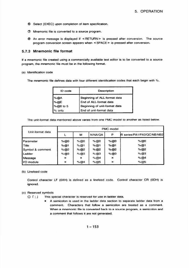
7/25/2019 FAPT Ladder for PC-Operator Manual
http://slidepdf.com/reader/full/fapt-ladder-for-pc-operator-manual 160/302
5. OPERATION
@ Select [EXEC] upon completion of item specification.
(?J Mnemonic file is converted to a source program.
@ An error message is displayed if c RETURN > is pressed after conversion. The source
program conversion screen appears when < SPACE > is pressed after conversion.
5.7.3 Mnemonic file format
If a mnemonic file created using a commercially available text editor is to be converted to a source
program, the mnemonic file must be in the following format.
(a) Identification code
The mnemonic file defines data with four different identification codes that each begin with %.
ID code Description
O/o@A Beginning of ALL-format data
%@E End of ALL-format data
%@O to 5
Beginning of unit-format data
% only End of unit-format data
The unit-format data mentioned above varies from one PMC model to another as listed below.
Unit-format data
L
PMC model
M N NAKIA P
Parameter
Title
Symbol & comment
Ladder
Message
l/O module
%@O
~ %@l
%@2
O/o@3
TO@0
%@l
%@2
“/0@3
%@4
% @O
%@l
% @2
O/o@3
%@4
% @5
% @O
%@l
%@2
%@3
(b)
Linefeed code
Control character LF (OAH) is defined as a linefeed code. Control character CR (ODH) is
ignored.
(c)
Reserved symbols
0
r J
This special character is reserved for use in ladder data.
A semicolon is used in the ladder data section to separate ladder data from a
comment. Characters that follow a semicolon are treated as a comment.
When a mnemonic file is converted back to a source program, a semicolon and
a comment that follows it are not generated.
I series/PAl/PA3/QC/NB/NB:
%
@O
%@l
% @2
% @3
% @4
O/o@5
1-153

7/25/2019 FAPT Ladder for PC-Operator Manual
http://slidepdf.com/reader/full/fapt-ladder-for-pc-operator-manual 161/302
5. OPERATION
0 r j
This special character is reserved for use in ladder and I/O module data.
A coton is used in the ladder data section to separate a net number from ladder
data. Data that precedes a colon is treated as a net number.
A colon is also used in the I/O module data section to separate a channel
number from 110 module data. Data that precedes a colon is treated as a
channel number.
In case of PMCRB4 RB4(STEP SEQ/RB5. RBG)/RC4’RC4(STEP
below format.
SEQ NB2), mnemonic file has
%@A
r ID code (See 10.1)
%@2-c
R0200.0 UNIT 3 POWER
II
Description of symbol
$1 ‘KEEP POWk?-ON’ ‘KEEP UNIT-3 POWER ON’ and comment (See 10.3)
R0200.1 UNIT 3 ACT
$1 ‘S’POWER$$’ -
‘KEEP UNIT-4 $$POWER$’ ON’
R0300.0
- Control character
$1 ‘KEEP POWER ON’
‘KEEP UNIT-4 POWER ON’
(See 10.2)
PO008 OPEN FRONT
$1 ‘OPEN FRONT COVER’
LO100 INITIALIZE
$1 ”
‘INITIALIZE OF SEQUENCE’
%
% @3
RD R1OO1.O
OR R120.3
AND R1000.2
WRT Y2000.4
(’
Net comment is written in here. Any characters
you enter by using personal computer is permitted.
3
1
escription of net
comment (See 10.4(l))
RD R1OO1.O
AND R1000.2
WRT Y23.4
(*SP 3
Designation of new page (for ladder diagram printing)
RD R1O1.O
(See 10.4(2))
OR R123.4
AND R100.2
WRT Y200.4
%
‘y
I
%E
Note)
A mnemonic file converted with version 08.1 or earlier is able to be converted to source
program with version 08.4 or later.
But a mnemonic file converted with version 08.4 or later is not able to be converted to
source program with version 08.1 or earlier.
1-154
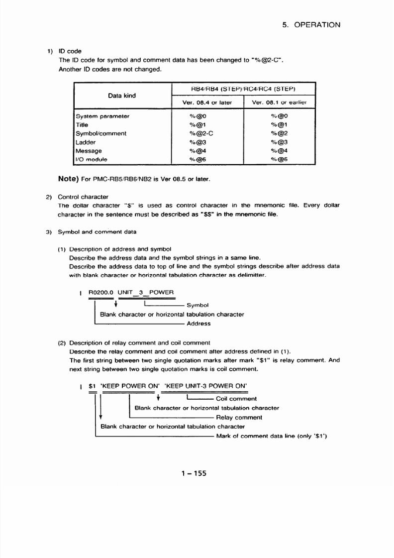
7/25/2019 FAPT Ladder for PC-Operator Manual
http://slidepdf.com/reader/full/fapt-ladder-for-pc-operator-manual 162/302
5. OPERATION
1)
ID code
The ID code for symbol and comment data has been changed to “%@2-C”.
Another ID codes are not changed.
Data kind
RB4’RB4 (STEP)‘RC4;RC4 (STEP)
Ver. 08.4 or later
Ver. 08.1 or earlier
System parameter
%
@O
% @O
Title
%@l
%@l
Symbol/comment
%@2-c
% @2
Ladder
% @a
%@3
Message
% @4
% (94
l/O module
% @5
% @5
Note)
For PMC-RB5 RBG/NB2 is Ver 08.5 or later.
2)
3)
Control character
The dollar character “S” is used as control character in the mnemonic file. Every dollar
character in the sentence must be described as “$$” in the mnemonic file.
Symbol and comment data
(1)
(2)
Description of address and symbol
Describe the address data and the symbol strings in a same line.
Describe the address data to top of line and the symbol strings describe after address data
with blank character or horizontal tabulation character as delimitter.
1 R0200.0 UNIT 3 POWER
--
Description of relay comment and coil comment
Describe the relay comment and coil comment after address defined in (1).
The first string between two single quotation marks after mark “$1” is relay comment. And
next string between two single quotation marks is coil comment.
1 $1 ‘KEEP POWER ON’ ‘KEEP UNIT-3 POWER ON’
Blank character or horizontal tabulation character
Mark of comment data line (only ‘$1’)
1-155
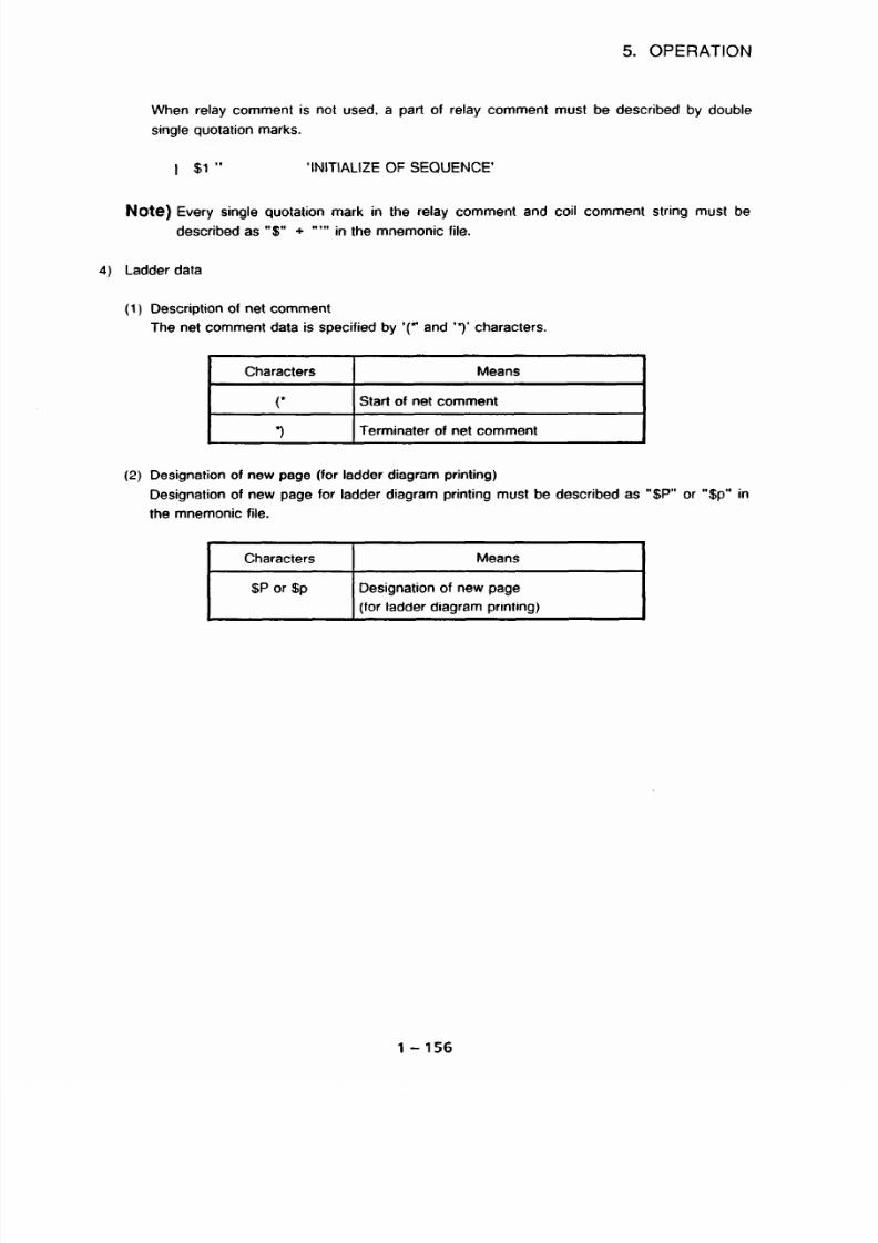
7/25/2019 FAPT Ladder for PC-Operator Manual
http://slidepdf.com/reader/full/fapt-ladder-for-pc-operator-manual 163/302
5. OPERATION
When relay comment is not used, a part of relay comment must be described by double
single quotation marks.
I $1 ”
‘INITIALIZE OF SEQUENCE’
Note) Every single quotation mark in the relay comment and coil comment string must be
described as “$” +
‘*“I in the mnemonic file.
4) Ladder data
(1) Description of net comment
The net comment data is specified by ‘(* and ‘3’ characters.
(2) Designation of new page (for ladder diagram printing)
Designation of new page for ladder diagram printing must be described as “$P” or “$p” in
the mnemonic file.
Characters
I
Means
$P or $p
Designation of new page
(for ladder diagram printing)
1-156
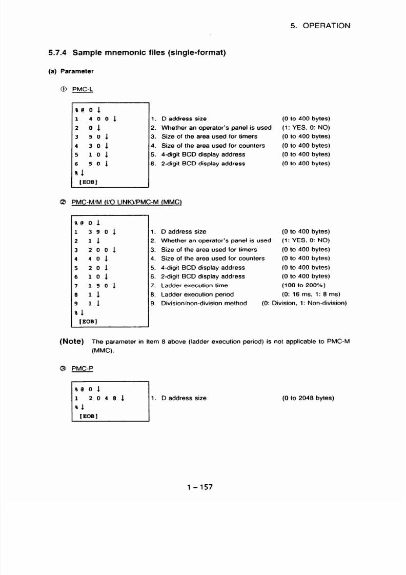
7/25/2019 FAPT Ladder for PC-Operator Manual
http://slidepdf.com/reader/full/fapt-ladder-for-pc-operator-manual 164/302
5. OPERATION
5.7.4 Sample mnemonic files
(a)
Parameter
0
PMC-L
8
ce
0 1
1
4001
2
01
3
501
4
301
5
101
6
501
81
tEoB1
(single-format)
1.
2.
3.
4.
5.
6.
D address size
Whether an operator’s panel is used
Size of the area
used for timers
Size of the area used for counters
4-digit BCD display address
2-digit BCD display address
PMC-M M (l/O LINK)/PMC-M (MMC)
se 0 1
1
3901
2
11
3
2001
4
401
5
201
6
101
7
1501
8
11
9
11
01
IEOBI
1.
2.
3.
4.
5.
6.
7.
B.
9.
D address size
Whether an operator’s panel is used
Size of the area used for timers
Size of the area used for counters
4-digit BCD display address
2-digit BCD display address
Ladder execution time
Ladder execution period
(0 to 400 bytes)
(1:
YES, 0: NO)
(0 to 400 bytes)
(0 to 400 bytes)
(0 to 400 bytes)
(0 to 400 bytes)
(0 to 400 bytes)
(1: YES, 0: NO)
(0 to 400 bytes)
(0 to 400 bytes)
(0 to 400 bytes)
(0 to 400 bytes)
(100 to 200%)
(0: 16 ms, 1: 8
ms)
Division/non-division method
(0: Division, 1: Non-division)
(Note)
The parameter in Item 8 above (ladder execution period) is not applicable to PMC-M
(MMC).
0 PMC-P
ae 01
1
20481
%l
IEOBI
1. D address size
(0 to 2048 bytes)
1-157

7/25/2019 FAPT Ladder for PC-Operator Manual
http://slidepdf.com/reader/full/fapt-ladder-for-pc-operator-manual 165/302
5. OPERATION
@ PMC-N/N (VO LINKRB4)
%@ 0 1
1 4040~
2 BINARY1
3 SOS-
4 PC-N1
5 8000001
6 581
7 0001
8 8100001
9 NOi
10 041
sl
[EOBI
m
MC Series
Counter data type
PASCAL execution time
Setting not required
PASCAL TCB start address
(4040: N, 4045: N (I ‘0 LINK))
(Binary or BCD)
(0 to 100%)
(PC-N (fixed))
(0 to FFFFFF (hexadecimal))
PASCAL PMC screen processing time ratio
(0 to 99%)
Ladder execution time (000 to 050%) (Note)
PASCAL data start address (0 to FFFFFF (hexadecimal))
Level-3 synchronization (NO: Asynchronous, YES: Synchronous)
10. PMC edition
(PMC edition (2-digit))
(Note) Set a value subtracting 100 from an actual value for the
"7. adder execution time”.
(Example) When an actual value desired for the ladder execution
time is 125%, set 025
to that setting.
PMC-RAl RA2IPAl /PA3’PB4RB4 (STED)/RB5/RBG
%@
0
1
2 BINARY1
2.
3 No1 3.
4 PMC- RAll 14.
81
[EOBI
(Note) When specifying
YES in Item 3 above (whether an operator’s panel is used), specify
the KEY address, LED address, KEY image address, and LED image address as
follows:
Counter data type
(Binary or BCD)
Whether an operator’s panel is used
(YES: Used, NO: Not used)
PMC model
(PMC-RAl/PMC-RA2’PMC
RB4iPMC-RB4 (STEP SEQ) PMC-
PAl/PMCPA3/PMCRB5/PMCRBG)
3 YES X0000 YOOOO ROOOO ROOlOl
1-158
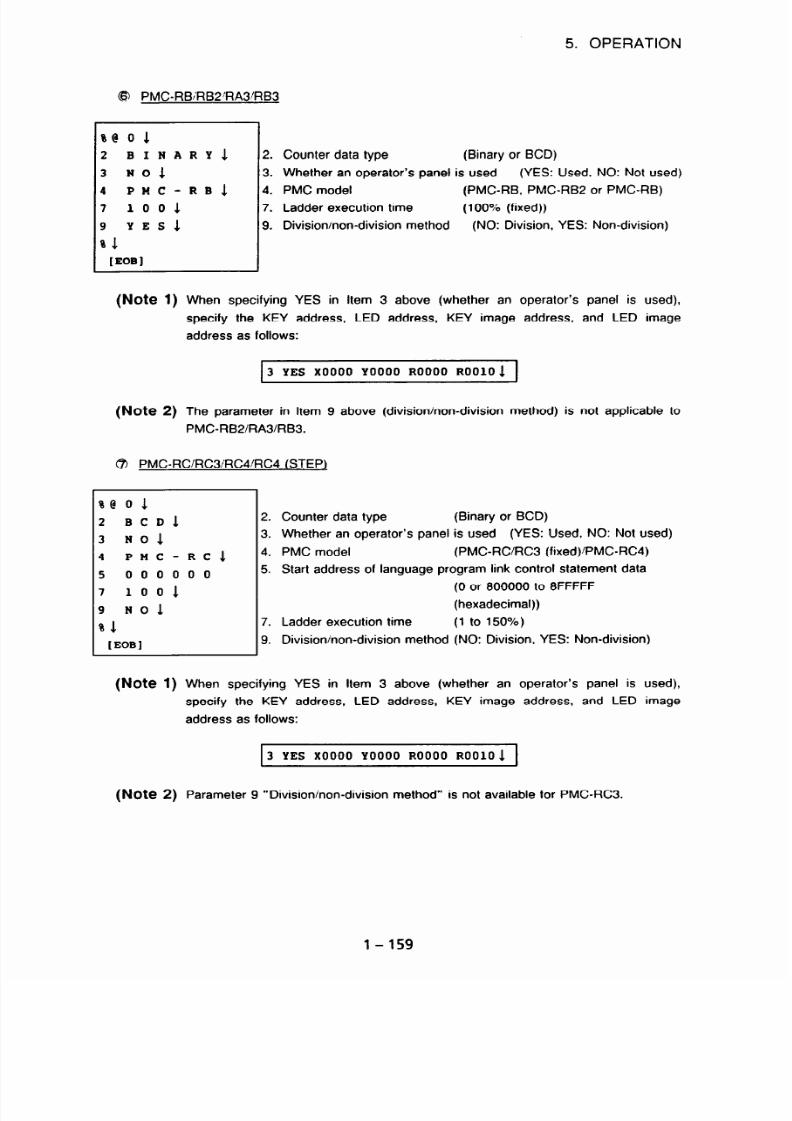
7/25/2019 FAPT Ladder for PC-Operator Manual
http://slidepdf.com/reader/full/fapt-ladder-for-pc-operator-manual 166/302
5. OPERATION
@ PMCRB,‘RB2RA3’RB3
se
0 1
2
BINARY1
3 NO1
4
PMC-RB1
7
1001
9
YES1
01
[EOBI
2.
3.
4.
7.
9.
Counter data type
(Binary or BCD)
Whether an operator’s panel is used (YES: Used, NO: Not used)
PMC model
(PMC-RB, PMCRB2 or PMC-RB)
Ladder execution time
(100% (fixed))
Division/non-division method
(NO: Division, YES: Non-division)
(Note 1)
When specifying
YES in Item 3 above (whether an operator’s panel is used),
specify the KEY address, LED address, KEY image address, and LED image
address as follows:
3 YES X0000 YOOOO ROOOO ROOlOl
(Note 2)
The parameter in Item 9 above (division/non-division method) is not applicable to
PMCRB2/RA3/RB3.
@ PMCRCIRC3iRC4IRC4 (STEP)
%e
0 1
2 BCDS.
3
ND1
4
PMC-RCl
5
000000
7
100s.
9
NOi
81
[EoBl
Counter data type (Binary or BCD)
Whether an operator’s panel is used
(YES: Used, NO: Not used)
PMC model (PMCRCRC3 (fixed)/PMC-RC4)
Start address of language program link control statement data
(0 or 800000 o 8FFFFF
(hexadecimal))
Ladder execution time
(1 to 150%)
Division/non-division method (NO: Division, YES: Non-division)
(Note 1) When specifying YES in Item 3 above (whether an operator’s panel is used),
specify the KEY address, LED address, KEY image address, and LED image
address as follows:
3 YES X0000 YOOOO ROOOO ROOlO5.
(Note 2)
Parameter 9 “Divisioninon-division method” is not available for PMCRC3.
1-159

7/25/2019 FAPT Ladder for PC-Operator Manual
http://slidepdf.com/reader/full/fapt-ladder-for-pc-operator-manual 167/302
5. OPERATION
@I PMC-QC/NB:NB2
%@ 0 1
2 BCDJ
3 NOS-
4 PHC-QCl
5 000000
6 501
7 1001
81
fEoB1
lb)
Title (common to all models)
%@ 11
01
MACHINE
TOOL
BUILDER
NAME 1
02
MACHINE
TOOL
NAMES
03
CNC 7
PMC
NAMES
04
PMC
PROGRAM NO.1
05
EDITION
NO.1
06
PROGRAM
DRAWING NO.1
07
DATE O
PROGRAMING1
08
PROGRAM
DESIGNED
BYi
09
ROM
WRITTEN
BY1
10
REMARKS1
el
fEOB1
(c)
Symbols and comments (common to all models)
2. Counter data type (Binary or BCD)
3. Whether an operator’s panel is used (YES: Used, NO: Not used)
4. PMC model (PMC-QCPMC-NB PMC-NB2)
5. Start address of language program link control statement data
(0 or 200000 to PFFFFF
(hexadecimal))
6. Percentage of language program execution time (1% to 99%)
7. Ladder execution time
(Always 100%)
(Note) If YES is specified in item 3 (whether an operator’s panel is used), specify the
addresses of KEY, LED, KEY image, and LED image as follows:
3
YES X0000 YOOOO ROOOO ROOlOl
%@ 2 1
x000.0 2PX.M START BELT CONVEYER 1
x000.1 2PY.M LIMIT SWITCH
ON1
%l
(EOBJ
l-160

7/25/2019 FAPT Ladder for PC-Operator Manual
http://slidepdf.com/reader/full/fapt-ladder-for-pc-operator-manual 168/302
5. OPERATION
@ Symbols and comments (at using the expanded symbol function)
(d)
Ladder (common to all models)
%@2-c
7
Symbol
R0200.0 UNIT-3-POWER
$1 'KEEP POWER ON' 'KEEP UNIT-3 POWER ON'
-
Coil Comment
Relay comment
R0200.1 UNIT-2-ACT
$1 *$*P~wER$$'
*KEEP UNIT-~ $$PowER$' 0~'
R0300.0
IControl code
$1
'KEEP POWER ON' 'KEEP INIT- POWER ON'
PO008 OPEN-FRONT
$1 'OPEN FRONT COVER'
LO100 INITIALIZE
$1 "
'INITIALIZE
OF
SEQUENCE'
- no Relay comment
%
[EOBI
0 FOR P G
--
%@ 31
RD X0.41
OR Y80.61
WRT DSOO.ll
SUB 11
RD.
NOT X3.01
SUB
4 1
21
81911
03001
SUB 21
81
[EOBI
1 -
161

7/25/2019 FAPT Ladder for PC-Operator Manual
http://slidepdf.com/reader/full/fapt-ladder-for-pc-operator-manual 169/302
5. OPERATION
8 FULL OPTION
-
%@3 1
NOOOOl: SUB
N00002: RD
SUB
N00003: RD
SUB
N00004: RD
SUB
N00005: SUB
N00006: SUB
YOOO07: SUB
VOOOOB: SUB
YOOO09: RD
DEC
WRT
300010: SUB
300011: SUB
I1
71
Pl
x0.0
68
LlOO
x0.1
73
LlOO
x0.1
65
P2
66
P2
69
LlOO
72
71
P2
RO.0
DO
21
DO.0
72
64
;
SP
;(SUBPRl
;(XADRSl
; JMPBl
;(LABELl
;(XADRS2
; JMPCl
;(LABELl
;(XADRSZ
; CALL1
;(SPlOOO
; CALLU5.
;(SPlOOO
) [SUB PROGRAM DATA NO.011 1
) [JUMPB LABEL LOOOOl] 1
) [LABEL Looooi] 1
) [JUMPB LABEL Looooi] J
)
[LABEL Looooi] 1
)
[JUMPB LABEL LOOOOl]l
) [SUB PROGRAM
DATA NO.lOOO] 1
) [SUB PROGRAM DATA NO.lOOO]J
; LBL 1
;(LABEL~
1
[LABEL LOOOO~]
1
;
SPE 1
:
-1
;
(SPlOOO ) [SUB PROGRAM
DATA NO.1000
;(RADRSOO
) 1
;(DADRS04
) 1
1
;
SPE 1
; END 1
1-162

7/25/2019 FAPT Ladder for PC-Operator Manual
http://slidepdf.com/reader/full/fapt-ladder-for-pc-operator-manual 170/302
5. OPERATION
0 FULL-OPTION (at using the expanded symbol function)
%@3 1
NOOOOl: SUB
N00002: RD
SUB
N00003: RD
SUB
N00004: SUB
N00005: SUB
N00006: SUB
N00007: RD
DE
WRT
N00008: SUB
N00009: SUB
81
71
Pl
x0.0
68
LlOO
x0.1
73
LlOO
69
LlOO
72
71
P2
RO.0
DO
21
DO.0
72
64
Symbol
;
SP
[_,
Relay comment
;(SUBPRl ) "SUB PROG. N0.01" 1
; [SUB PROGRAM DATA NO.011 1
L--
Coil comment
;(XADRSl ) "JUMPB LABEL Lool" l-_-1
; JMPBJ
no Comment
;(LABELl )l
; [LABEL ~ooool] 1A
no Relay comment
;(XADRSZ ) "JUMPB LABEL LOOl"$
; JMPCJ
;(LABELl )l
; [LABEL ~00001
;
LBL 1
;(LABELl )1
; [LABEL LOOOOlJ1
; SPE 1
: -1
;
(SPlOOO
)
"SUB PROGRAM DATA NO.l"l
;(RADRSOO ) 1
;(DADRSOII ) 1
1
; SPE 1
; END 1
1-163

7/25/2019 FAPT Ladder for PC-Operator Manual
http://slidepdf.com/reader/full/fapt-ladder-for-pc-operator-manual 171/302
5. OPERATION
@ LABEL/SUB-PROGRAM
H3 1
;UBPRl SP
RD
JMPB
RD
JMPC
RD
CALL
CALLU
LABEL1 LBL
SPE 1
iPlOO0 SP
RD
DEC
WRT
SPE 1
END 1
1 1
71 ;<Pl
XADRSl :<Xo.o
LABEL1 :<LlOo
XADRSZ ;<Xo.l
LABEL1 ;<Lloo
XADRSZ ;<Xo.l
SPlOOO :<P2
SPlOOO ;<P2
;<LlOOO
;<P2
RADROO ;<RO.O
DADR04 ;<DO
21
DO.0 1
> [SUB PROGRAM DATA NO.011 1
> [JIJMPB ABEL LOOOO1]1
> [LABEL Looool] 1
> [JUMPB LABEL ~ooool] 1
> [LABEL L00001] 1
> [JUMPB LABEL Looool] 1
> [SUB PROGRAM
DATA NO.looo]1
> [SUB PROGRAM
DATA NO.lOoo] 1
> [LABEL Looooi] 1
> [SUB PROGRAM DATA NO.lOoo] 1
'
1
’ 1
6) LABEL/SUB-PROGRAM (at using the expanded symbol function)
%@3 1
SUBPRl SP
RD
JMPB
RD
JMPC
LABEL1 LBL
SPE 1
SPlOOO SP
RD
DEC
WRT
SPE 1
END 1
% 1
I Address I Relay comment
SUBPRl :<Pl >. "SUB PROG. N0.01"
; [SUB PROGRAM DATA NO.011 1
r
Symbol
- Coil comment
XADRSl ;<XO.o > 'JUMPB LABEL LOOl"1
LABEL1 ;<LlOO
>l
;
[LABEL Looooi] 1
XADRS2 ;<XO.l
> "JUMPB LABEL LOOl"l
LABEL1 ;<LlOO
> [LABEL Looool] 1
;<LlOOO >1
;
[LABEL Looool] 1
;<P2 > "SUB PROGRAM NO.l"l
RADROO ;<RO.O
' 1
DADR04 ;<DO
'
1
21
DO.0 1
1-164

7/25/2019 FAPT Ladder for PC-Operator Manual
http://slidepdf.com/reader/full/fapt-ladder-for-pc-operator-manual 172/302
5. OPERATION
(e)
Message (other than PMC-L, PMC-M/M (I/O LINK)/M (MMC), PMC-P)
re 4 1
A0 0 0 2100020
ATC DOOR NOT CLOSE1
AOO.l
2101022 SPINDLE SPEED
ARRIVA
L SIGNAL
NOT
ON1
AO0.2
2100020
EDTOK KEY
SWITCR
ONi
%l
[EOBI
(f1
I/O module (other than PMC-UP)
%@ 5 1
x000
1 0 1 ID64Al
YO08 1 0 4 OD64Bl
81
[EOBI
L
(Note) The ID code depends on the model as follows:
.
%@4 :
PMC-M/M (I/O LINK)/PMC-M (MMC)
0
%@5 :
PMC-N/N (I/O LINK), PMC_RAl/RA2/RB/RB2/RC
1-165
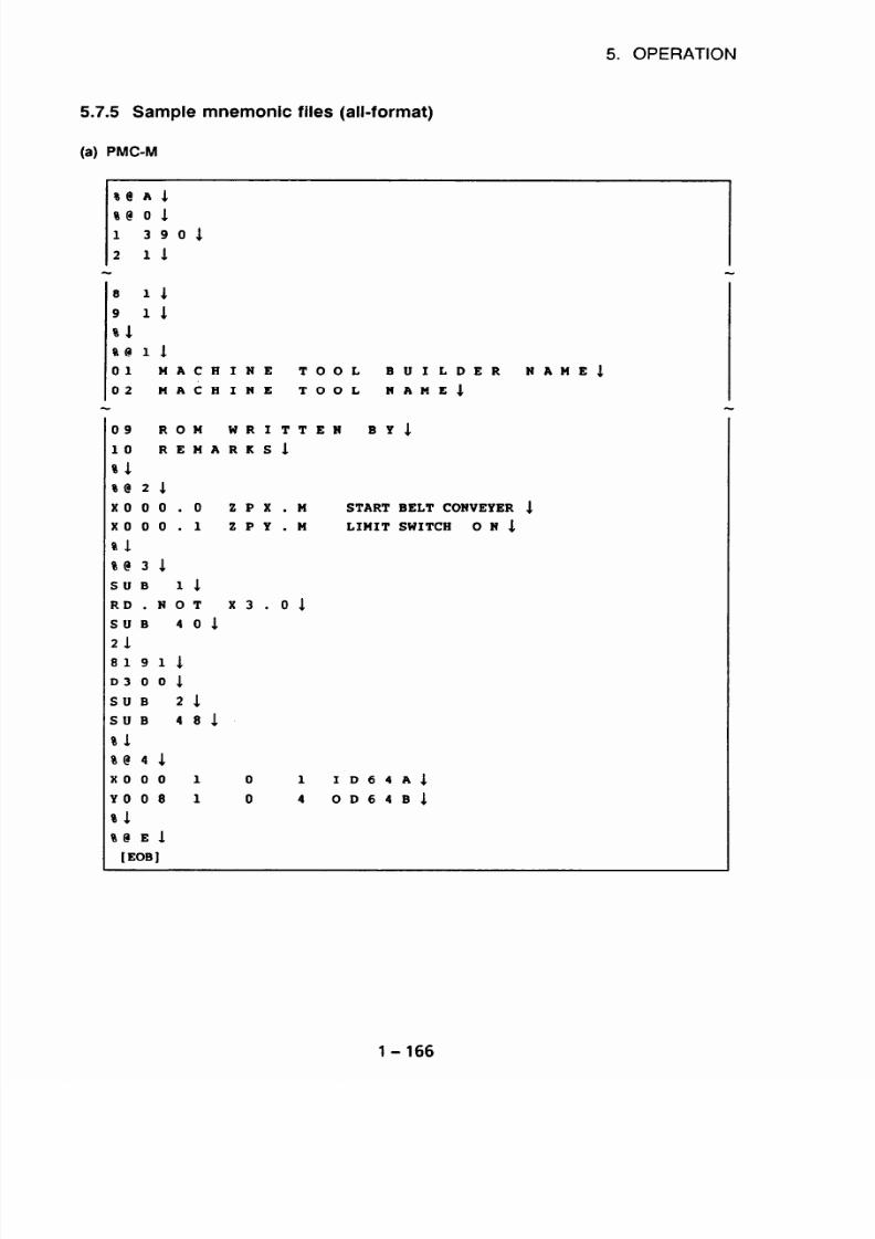
7/25/2019 FAPT Ladder for PC-Operator Manual
http://slidepdf.com/reader/full/fapt-ladder-for-pc-operator-manual 173/302
5. OPERATION
5.7.5 Sample mnemonic files (all-format)
a) PMC-M
%@ A
1
%@0 1
1 3901
2 11
8 11
9 11
el
ee 11
01
MACH
02 MACH
09
ROM
10
REMA
sl
%@ 2 1
x000.0
x000.1
%l
%@
3
1
SUB 11
RD.
NOT
SUB
401
21
81911
03005
SUB 21
SUB
481
%l
se
4
1
x000 1
YOO8 1
%l
%@ E 1
[EOBI
INE
TOOL BUILDER
INE TOOL NAME1
WRITTEN
BYA
RKSl
NAMES
2PX.M
START BELT CONVEYER 1
2PY.M
LIMIT SWITCH
ONS.
x3.01
0 1 ID64Al
0
4
OD64Bl
1-166

7/25/2019 FAPT Ladder for PC-Operator Manual
http://slidepdf.com/reader/full/fapt-ladder-for-pc-operator-manual 174/302
5. OPERATION
PMC-N
1
%@ A 1
%@ 1
1 sosol
2 BINARY1
9 NO1
10
041
%l
%@ 11
01
MACHINE
TOOL BUILDER
02 MACHINE TOOL NAME1
NAME1
09
ROM
WRITTEN
BY1
10 REMARKS1
sl
%@ 21
x000.0 2PX.M
x000.1 2PY.M
sl
%@
3 1
SUB 11
RD. NOT K3.01
SUB
401
21
81911
DO001
SUB 21
SUB
481
%l
%@ 4 1
AOO.0 2100020
AOO.l 2101022
START BELT CONVEYER 1
LIMIT SWITCH
ON1
ATC
DOOR
NOT CLOSE1
SPINDLE SPEED ARRIVA
L SIGNAL NOT
ON1
rl
%@ 51
x000
1 0 1
ID64Al
YOO8
1 0 4
OD64Bl
%l
%@ El
tEoB1
1-167

7/25/2019 FAPT Ladder for PC-Operator Manual
http://slidepdf.com/reader/full/fapt-ladder-for-pc-operator-manual 175/302
5. OPERATION
(cl
PMC-FIB
%@
1
se
0 1
2 BCDJ.
3 NO1
7 1001
9 YES1
%l
%@11
01 MACHINE
02 MACHINE
TOOL
BUILDER
TOOL
NAME
09
ROM WRITTEN BY'
10 REMARKS1
%l
%@2 1
x000.0 ZPX.M
x000.1 ZPY.M
sl
oe
3
1
SUB 11
RD.
NOT K3.01
SUB
401
21
81911
D3001
SUB 21
SUB
481
sl
%@4 1
AOO.0 2100020
AOO.l
2101022
J
START
LIMIT
BELT CONVEYER
SWITCH 0 N 1
ATC DOOR N
SPI NDLE SP
L
SIGNAL
NOT
ONS.
%l
%@ 5 1
x000 1 0 1 ID16
YOO8 1 0 4 OD32
%l
%@ E 1
[EOBI
cl
Al
NAME1
1
OT
CLOSE1
EED
ARRIVA
l-168

7/25/2019 FAPT Ladder for PC-Operator Manual
http://slidepdf.com/reader/full/fapt-ladder-for-pc-operator-manual 176/302
5. OPERATION
(d)
PMC-RB4
%@A 1
%@O1
2 BINARY&
3 NO1
4 PMC-RB4 1
%
1
%@l1
01 MACHINE TOOL BUILDER NAME1
10 REMARKS1
% 1
ae2-c 1
RO200.0 UNIT-3-POWER1
$1 'KEEP POWER ON'
'KEEP UNIT-3 POWER ON'1
R0200.1 UNIT-2-ACT1
$1 '$'P~wER$$'
'KEEP UNIT-4 $$POWER$' ON'J.
RO300 0 1
$1 'KEEP POWER ON'
'KEEP UNIT-4 POWER ON'1
PO008
OPEN-FRONT1
$1 'OPEN FRONT COVER' 1
LO100
INITIALIZE1
$1 "
'INITIALIZE OF SEQUENCE'&
$1
$@3
1
RD RlOOl.03.
3R R120.3 1
9ND R1000.2 1
nlRT 2000.4 1
(*
Inscribe the net comment here.
Any characters
which are input with personal computer can be used.
1
Net
comment
R)
RD R1OO1.O1
9ND R1000.2 1
dRT Y23.4 1
(* SP
form feed position (in Ladder diagram)
RD
R1O1.O 1
OR R123.4 1
AND R100.21
WRT Y200.41
% 1
%@a 1
AOO 0 2100020 ATC DOOR NOT DLOSEJ
AOO.l 2101022 SPINDLE SPEED ARRIVAL SIGNAL
NOT ON 1
%
1
%@5
1
X000 1 0 1 IDlBC&
YO08 1 0 4 OD32Al
%
1
%@E
1-169

7/25/2019 FAPT Ladder for PC-Operator Manual
http://slidepdf.com/reader/full/fapt-ladder-for-pc-operator-manual 177/302
5. OPERATION
5.7.6 The note if the step sequence function is selected when setting a
model
When using the step sequence method, mnemonic instructions cannot be coded.
The mnemonic conversion functions need following notes:
1)
2)
3)
Programming by Mnemonic instructions
A step sequence program cannot be created with mnemonic instructions. It is impossible to
create a step sequence program with a text editor, or to read the program into FAPT LADDER
by means of mnemonic-to-source conversion.
Source-to-Mnemonic and Mnemonic-to-Source Conversions
If source-to-mnemonic conversion is executed for a step sequence source program, only ladder
subprograms are converted to mnemonics, step sequence subprograms being ignored. If a
step sequence source program is subjected to source-to-mnemonic conversion, then to
mnemonic-to-source conversion, the original source program will not be replicated.
Source Program Conversion using Mnemonics
A program can be converted by using mnemonics, as shown below:
I PMC-RB3
, * PMCRC3
1
(STEP SEQ)
A program for the PMC-FIB4 (STEP SEC?) cannot be converted for use with the PMCRC4
(STEP SEC), because of the reason explained in Section 7.2. The program can be converted
if a ROM file is used, however. (For details of this conversion, see the description of the
decompiler.)
l-170

7/25/2019 FAPT Ladder for PC-Operator Manual
http://slidepdf.com/reader/full/fapt-ladder-for-pc-operator-manual 178/302
5. OPERATION
5.7.7 User batch file execution
The batch file FLMNE.BAT can be executed by suspending the execution of FAPT LADDER.
A user’s own batch file generated by editing the contents of the FLMNE.BAT file with a standard
text editor can also be executed.
Examole
1
The execution of FAPT LADDER is suspended and text editor VZ is activated. (In this case,
VZ must be defined in the environment variable PATH beforehand.)
[Operation ]
Use a standard text editor to create the batch file FLMNEBAT as follows:
vz
Select MNEEDT (mnemonic editing) from the main menu.
The mnemonic menu screen appears.
Select ([BATCH] (user batch file execution).
The following message appears:
Execute
'FLMNE.BAT'.
Add parameter(s)? [A(Add), N(Not add), S(Stop)]
Specify A (Add), and specify *.HEX as the parameter.
VZ is activated and a list of files
with the extension .HEX is displayed.
To restart FAPT LADDER. terminate VZ.
I
eturn to FAPT LADDER. Hit any key
I
Press any key. The screen display
returns to the mnemonic menu screen.
Example 2
The execution of FAPT LADDER is suspended.
Then, the command processor
COMMAND.COM is activated and MS-DOS commands are enabled. Create FLMNE.BAT as
follows:
COMMAND
I
1 - 171

7/25/2019 FAPT Ladder for PC-Operator Manual
http://slidepdf.com/reader/full/fapt-ladder-for-pc-operator-manual 179/302
II APPLICATIONS
(NOTES ON THE PC ENVIRONMENT)

7/25/2019 FAPT Ladder for PC-Operator Manual
http://slidepdf.com/reader/full/fapt-ladder-for-pc-operator-manual 180/302
1.
COMMON OPERATIONS FOR THE
PC9801 AND IBM PG’AT
1. COMMON OPERATIONS FOR THE PC9801 AND IBM PC/AT
1.1 Function for Transferring Data between the P-G and PC
This function is used to transfer data in ASCII (mnemonic) format between a P-G (including the
Mate and Mark II) and a PC via an RS232 cable. The command for NEC PC9801 series PCs is
FLOAD98, and the command for IBM PC/ATs is FLOADAT.
Use this function to transfer the sequence program between the P-G and a personal computer if
(data exchange function) cannot be used with 3.5” floppy, for example, in a system with the P-G
provided with a 5” floppy disk drive or in a system with a personal computer not provided with a
3.5” floppy disk (1.2 Mbytes) drive.
1.1.1
Command input during startup
(1)
Uploading
Loads the FAPT LADDER mnemonic data into the PC from the P-G via the RS232 port.
FLOAD98 - [name of file for storing uploaded data] - -u (for PC9801)
FLOADAT - [name of file for storing uploaded data] - -u (for IBM PC/AT)
When a file with the same name as the file specified for receiving data already exists in the
current directory, the following message is displayed.
File is exist. Over write? <Y/N >
(2)
Downloading
Loads the FAPT LADDER mnemonic data into the P-G from the PC via the RS232 port.
FLOAD98
- [name of file for storing downloaded data] - -d (for PC9801)
FLOADAT _ [name of file for storing downloaded data] _ -d (for IBM PC/AT)
As shown above, the load commands have the following two parameters:
-u: Uploads data from the P-G to the PC.
-d: Downloads data from the PC to the P-G.
(Note) The above parameters can be specified with either lowercase or uppercase characters.
2-l

7/25/2019 FAPT Ladder for PC-Operator Manual
http://slidepdf.com/reader/full/fapt-ladder-for-pc-operator-manual 181/302
1. COMMON OPERATIONS FOR THE PC9801 AND IBM PC/AT
1 1.2 Communications settings
PC side
NEC PC9801 Series
baud rate:
(MS-DOS SPEED command) character length:
parity:
stop bits:
X parameter:
4800 or 9600
7 bits
even parity
2 bits
none
IBM PC/AT Series
MODE COMI: 4800,E,7,2
(PC DOS MODE command) MODE COMl:
9600,E,7,2 (for 9600 baud)
P-G side
IO NC,CNl,Fl ,F6
10 NC,CNl,Fl,F6,BRlO (for 9600 baud)
(Note 1) The baud rate can be set to either 4800 or 9600. However, note that when the PC
baud rate is set to 9600, the parameter BRlO must be added to the baud rate setting
for the P-G.
(Note 2)
It is necessary to set these communications setting only for doing this operation. After
using this function, please restore the communications settings as the section 2.1
(Chapter 1).
The CN number is not fixed. For the P-G or P-G Mark II, the CN number can be any setting from
CNl to CN4. For the P-G Mate, the CN number can be any setting from CNl to CN3. However,
note that the CN number selected here must match the CN number of the IO command. Use the
cables specified in Appendix 1.
2-2

7/25/2019 FAPT Ladder for PC-Operator Manual
http://slidepdf.com/reader/full/fapt-ladder-for-pc-operator-manual 182/302
1. COMMON OPERATIONS FOR THE PC9801 AND IBM PC/AT
peration examde
During uploading
Operation procedure
c PC > < PG > Turn on power.
Example of input and screen contents
< PG > Enter IO command settings.
; IO C,CNl ,Fl ,FG(,BRlO)
c PC > PC9801 Series: Enter SPEED command
; (See Section 2 of Communications
settings.
i Settings)
IBM PC/AT Series: Enter MODE
command settings. i
< PG > Store transmission data in P-G memory.
: Press the [F2] key to select menu item
i no.2.
< PC > Execute FLOAD98. Enters waiting state.
i FLOAD98 FILE NAME -u
Execute FLOADAT. Enters waiting state. i FLOADAT FILENAME -u
i < PC > “LOADER START” is displayed.
< PG > Set [F6] ON. Select no.4 on the menu.
i
c PG > Select any entry from 1 to 7 on the
submenu.
3egins transmission.
i c PG > “EXECUTING” is displayed.
Completes transmission.
e PG > Returns to the menu.
i =zPC > “Operation Complete” is displayed.
( PC > The message “Operation Complete” is
i
“HIT ANY KEY” is displayed.
displayed, followed by the prompt “HIT
;
ANY KEY”. Hit any key to end operation. i
During downloading
Operation procedure
Example of input and screen contents
< PC > < PG > Turn on power.
< PG > Enter IO command settings.
< PC > Enter SPEED command settings.
; IO NC,CNl,(BRlO,)Fl,FG
i (See Section 2 of Communications
i Settings)
< PG > Turn on [Fl] key. Select no.2 on the
menu. Enters waiting state.
< PC > Execute FLOAD98.
Execute FLOADAT.
Begins transmission.
Completes transmission.
<PG> Returns to the menu.
=zPG > “EXECUTING” is displayed.
; FLOAD98 FILE NAME -d
; FLOADAT FILENAME -d
i <PC> “Output Start” is displayed.
< PC > The message “Operation Complete” is
: < PC > “Operation Complete” is displayed.
displayed, followed by the prompt “HIT
i
“HIT ANY KEY” is displayed.
ANY KEY”. Hit any key to end operation. i
2-3

7/25/2019 FAPT Ladder for PC-Operator Manual
http://slidepdf.com/reader/full/fapt-ladder-for-pc-operator-manual 183/302
1. COMMON OPERATIONS
FOR THE PC9801 AND IBM PG’AT
1 .1.3 Protocol
Durinq uploadinq
When the FLOAD98 or FLOADAT command is executed on the PC side, a communications
request is issued for the P-G and reception begins. After all data has been received, DC 3 is
sent and transmission is completed.
0 DC 1 code is sent to the P-G (data transmission request).
8 Data is received.
Q Completion code is received and reception is completed.
@ DC 3 code is sent.
Transmission and reception both use the l-byte machine-dependent
output.
Durina downloadinq
BIOS call for input and
After the P-G issues a transmission request, the P-G enters the waiting state. FLOAD98 or
FLOADAT is activated in the PC, then transmission begins. After all data has been sent. DC 4
is sent and transmission is completed.
0 The P-G issues DC 1.
8 DC 2 code is sent to the P-G.
@ Data is sent.
@ DC 4 code is sent.
Transmission and reception both use the l-byte machine-dependent
output.
1.1.4
BUSY control
BIOS call for input and
When the transmission speed is faster than reception processing, BUSY control is performed by
issuing the DC 1 and DC 3 codes. In the PC9801 series, the X parameter in the DOS SPEED
command is set to off, which allows the application to provide support for BUSY control. In the
IBM PC/AT series, there is no X parameter, which effectively has the same result.
2-4

7/25/2019 FAPT Ladder for PC-Operator Manual
http://slidepdf.com/reader/full/fapt-ladder-for-pc-operator-manual 184/302
1. COMMON OPERATIONS FOR THE PC9801 AND IBM PC/AT
1.1.5 Data start and end codes
The system will automatically determine which of the following seven pairs of start and end codes
is used. When none of these codes are used, an error message is displayed and operation
terminates.
1.1.6 Data conversion (return codes)
(Note)
The end codes
shown here must appear at
the beginning of a line. In
other words, strictly speaking,
a data reception end code is
actually denoted by the
sequence CR + LF + an end
code. End codes (% etc.)
appearing within comments
are ignored.
(1) When an LF code (OAH) is received, it is converted into two characters, the first of which is CR
(ODH) followed by LF (OAH).
(2) When a CR code (ODH) is received, it is discarded.
(3) When an end code (DE) is received, CR (ODH) and LF (OAH) are appended to it in that order.
1.1.7 Transmission and receive data
Until a data start code (DS) is received, data is discarded.
1 1
1 1
. . .-Discarded
Valid data I...
After the end code (DE) has been sent or received, DC 3 is sent for uploading or DC 4 is sent for
downloading, then the file is closed.
2-s

7/25/2019 FAPT Ladder for PC-Operator Manual
http://slidepdf.com/reader/full/fapt-ladder-for-pc-operator-manual 185/302
1. COMMON OPERATIONS FOR THE PC9801 AND IBM PC/AT
1 .1.8 Error detection and messages
This software detects the following four types of
errors.
(1)
(2)
(3)
(4)
When there is an error in the command line
Error in the file name, -u. or -d.
Parameter Error
FLOAD98 FILENAME -u/-d set parameter. (FILNAME, upload or download.)
When the specified file cannot be found
Output file cannot be found or file for receiving cannot be opened.
I~- ~~~
annot open output file
I
When data not in the FAPT LADDER format is sent or received
Wrong data received
When there is a definite problem with the start code,
Start Code error detected
or there is a definite oroblem with the end code
I
nd code error detected
This software only detects errors in the command line and in the FAPT LADDER format.
This software does not support detection of errors in the contents of FAPT LADDER data.
Messaaes
When the file name specified as the file for receiving data already exists in the current directory,
the following message is displayed.
File is exist. Over write? <Y/N >
2-6

7/25/2019 FAPT Ladder for PC-Operator Manual
http://slidepdf.com/reader/full/fapt-ladder-for-pc-operator-manual 186/302
1. COMMON OPERATIONS FOR THE PC9801 AND IBM PC/AT
1.1.9 Error detection and handling
1. Incorrect entry found in the command line.
2. Specified file cannot be opened.
3. Data not in the FAPT LADDER format was sent or received.
The following causes can be considered for the above errors:
0 The end code has been omitted (% or %@E was omitted).
0 The start code has been omitted (%@‘, where is A or 0 to 5. was omitted).
Garbage data exists at the beginning of the file.
Garbage data exists between each unit of data.
The file format is completely different from the FAPT LADDER format.
When any of the above errors is detected, the current operation is canceled.
During downloading, if an error is detected on the PC, the system will return to the DOS
screen. At the same time, a %, %@E or other end code is sent to the P-G to return it to the
menu screen.
4. Others
When, for some reason, data transfer is interrupted
(When the power to the PC or P-G is interrupted during operation, etc.)
When data transfer is interrupted during uploading, the system will enter a waiting state until
data transfer is restarted. (To interrupt the waiting state, press cCTRl_> + <C >).
When data transfer is interrupted during downloading, the data becomes corrupt and data
transfer must be started over from the beginning.
2-7

7/25/2019 FAPT Ladder for PC-Operator Manual
http://slidepdf.com/reader/full/fapt-ladder-for-pc-operator-manual 187/302
1. COMMON OPERATIONS FOR THE PC9801 AND IBM PCiAT
1.2
Convert the PMC Type of Sequence Program
By changing the mnemonic file, it is possible to convert some PMC type sequence program to
another type of it.
1.2.1 Converting by system parameter editing
On the following
parameter of the
However, format
different.
PMC type, it is possible to edit the different PMC type data by changing system
mnemonic data.
of the system parameter, usable functional instructions and range of address are
1~
CNC TYPE
I
PMC TYPE
FS16f 18-T/M
PMCRAl/RA2/RA3/RB/RB2/RB3/RB4/RB YRB6~RC/RC3/RC4
Power Mate-MODEL D
PMC-PA1 /PA3
(1)
(2)
(3)
[Example: PMC-RB + PMC-RC3]
Set the PMC type to PMC-RB and convert the original source program to mnemonic file.
Change the system parameter of the mnemonic fife to PMCRC3 with a standard text editor.
Set the PMC type to PMC-RC3 on FAPT LADDER system and convert the mnemonic
file(+(2)) to source program.
Original file (PMC-RB)
%@A
%@O
2 ECD
3 NO
4 PMC-RB
7 100
9 YES
%
%@l
01 ABC-KIKAI
02 S-DRILL
%
%@5
X000 1 0 1 ID16C
YO08 1 0 4 OD32A
%
%@E
Change
system parameter
b
Converted file (PMCRC3
%@A
%@O
2 BCD
3 NO
4 PMC-RC3
5 000000
6 50
7 100
%
%@l
01 ABC-KIKAI
02 S-DRILL
%
$65
X000 1 0 1 IDl6C
YO08 1 0 4 OD32A
8
%@E
2-8

7/25/2019 FAPT Ladder for PC-Operator Manual
http://slidepdf.com/reader/full/fapt-ladder-for-pc-operator-manual 188/302
1. COMMON OPERATIONS FOR THE PC9801 AND IBM PC/AT
1.2.2 Convert with signal address converter
CONVERTER
FILE NAME
APPLICABLE PMCCNC TYPE
REFERENCE MATERIALS
FS()T CNV.SYM PMC-uM/M(MMC)
-+ PMC-RAl iRA2IRA3IRB FANUC PMC
-
(FSO-T)
/RB2’RB3’RB4’RB5’ PROGRAMMING MANUAL
RBG/RC/RC3/RC4
(FS16/18-T)
(LADDER LANGUAGE)
B-61 863E
FSOM CNV.SYM PMC-UM/M(MMC) + PMCRAl/RA2/RA3/RB
-
(FSO-M)
/RB2/RB3 RB4/RB5/
RBG/RC/RCB/RC4
(FS16/18-M)
PM-C_CNV.SYM PMC-P + PAllPA
(Power Mate
(Power Mate
-MODEL C)
-MODEL D)
(1)
(2)
(3)
(4)
(5)
Set PMC type to PMC-P, and convert the original source program to the mnemonic file. (+A.)
Set PMC type to PMC-PAl. And input the source program name and select [END] at edit
mode without editing the ladder program.
Convert the source program(2) to the mnemonic file. (+B.)
Quit FAPT LADDER, and activate any standard text editor.
(Select the mnemonic file name(3) to edit.)
Replace the symbol and comment data of the mnemonic file (PMC-PAl) to the converter file
(PM-C.CNV). (+C.)
(6)
Replace the ladder data of mnemonic file (PMC-PAl) to the ladder data of the original
mnemonic file (PMC-P). (+D.)
(7)
Complete the text editor, and activate FAPT LADDER.
(8)
Set PMC type to PMC-PAl, and convert the mnemonic file@) to source program.
(3)
Select edit mode, and delete the symbol and comment data.
(Note)
The converter file is stored in the directory APPENDIX of module floppy disk.
[Example: PMC-P + PMC-PA11
2-9

7/25/2019 FAPT Ladder for PC-Operator Manual
http://slidepdf.com/reader/full/fapt-ladder-for-pc-operator-manual 189/302
A. Original file
1. COMMON OPERATIONS FOR THE PC9801 AND IBM PC/AT
(PMC-P)
%@A
%@O
1 2048
%
be1
B
b@2
b
b@3
?D
X21.4
iRT G121.4
tD.NOT X22.3
fRT.NOT 6122.3
:UB 1
IUB 2
fRT 6121.4
D.NOT X22.3
rRT.NOT 6122.3
UB 1
UB 2
@E
Convert file
PM-C CNV.SYM
-
%@2
60004.3 G68.3
60005.0 695.0
60005.2 695.2
60005.3 G95.3
60005.6 G83.7
G0006.2 675.2
60006.4 674.4
60007.2 G68.2
G0007.5 684.5
X1027.4 X23.4
X1027.5 X23.5
X1027.6 X23.6
X1027.7 X23.7
I$-
c
D. insertion ,-
B. Converted file
(PMC-PAl)
%@A
%@O
2 BINARY
3 NO
4 PMC-PA1
%
eel
%
se2
b
ae3
b
se4
b
se5
b
b@E
2-10

7/25/2019 FAPT Ladder for PC-Operator Manual
http://slidepdf.com/reader/full/fapt-ladder-for-pc-operator-manual 190/302
1. COMMON OPERATIONS FOR THE PC9801 AND IBM PC/AT
1.2.3 Using data in a sequence program for another program
Data (such as title, symbol & comment, ladder, message, and I/O module data) in a sequence
program can be used for another sequence program, by the following method.
The range of addresses used varies from one model to another. They may have to be modified.
Refer to the programming manual of the respective models.
[Example : Using the symbols & comment data of the PMC-FIB for the PMC-RC3]
%@A
%@O
2 BCD
3 NO
4 PMC-RB
7 100
9 YES
%
eel
%@2
x000.0 2PX.M
x000.1 2PY.M
%@A
%@O
2 BCD
3 NO
4 PMC-RC3
5 000000
6 50
7 100
9 YES
%
%@l
-
X000.0 ZPX.M
X000.1 ZPY.M
1.3 Standard Symbol Data
When a mnemonic file and the standard symbol data are combined, it is possible to use the
standard symbol name provided by FANUC.
CNC TYPE
DATA FILE NAME
FS16/18-T F16&F18-T.SYM
FS16/18-M FlG&F18-M.SYM
Power Mate-MODEL D
PM-D.SYM
Power Mate-MODEL H PM-H.SYM
(Note) The standard symbol data is stored in the directory APPENDIX.
2-11

7/25/2019 FAPT Ladder for PC-Operator Manual
http://slidepdf.com/reader/full/fapt-ladder-for-pc-operator-manual 191/302
1. COMMON OPERATIONS FOR THE PC9801 AND IBM PC/AT
1.4 Changing Printer Output Format
Each parameter file of this software can be rewritten using a commercially available text editor so
that the output format shown in each of the following frames can be changed.
1 Diagram output %
L
-AMROFTRP. DAT
1. Change the paper
selection name
2. Set the top margin
3. Set the net interval
4. Set the printer model and
paw
-CROSSING. DAT
(Setting the cross-reference
list output format)
8. Set the output format
guidance information
9. Set the output information
10. Specify the output format
11. Set the read/write coil
guidance information
12. Specify the linefeed
13. Specify the page break
-PR201-10 . INF -
PR201-15 . INF
PR201-A4 . INF
PRlO-A . INF
PRlS-A . INF
PRA4-A . INF
ESC-P-10 . INF
ESC-P-15 . INF
ESCPl O-A. INF
ESCPl5-A. INF
-FANUC-10. INF -
5. Set the line spacing
6. Set the left margin
7. Set the title of printout
For these parameter files, do not change any item not described here.
2-12

7/25/2019 FAPT Ladder for PC-Operator Manual
http://slidepdf.com/reader/full/fapt-ladder-for-pc-operator-manual 192/302
1. COMMON OPERATIONS
FOR THE PC9801 AND IBM PC/AT
- Print format
lo-inch/ASCII
.
.
*lo-inch/graphic
15-inch/ASCII
15-inch/graphic
A4 portrait/ASCII
A4 portrait/graphic
.
.:,‘~:.:,~~:-:
- ,:gq:
5
$ > ,. : :
.,...
6”:~:~7~8~,.‘g~~10 ~j$.#)..
;
‘,.y “F
.((.,.,,...,._._.
,,..
:.’
:.......) .:
b-1 ‘i
.:
I-
A. SETUP screen (diaqram output)
:’:
:’
:
:
:
:.
:’
:’
.*.
:
:
:, ...:..
:... , . ::.,~,,.,.... .,>,,:
., .‘. ..:.. >:
#PAPER=lO-G
: flO-A=lO-inch/ASCII
i
LENGTHL=ll
i LENGTH=11
:
WIDTHL=lO
:
WIDTH=10
;
PTCHL=lS/lZO
: LI
: z
b-2’
LEFTMGL=O
LEFTWG=O
TOPMGL=O
TOPMG=O
LCNTL=4
_FI
LE+-ij
O_FILE;PRTDAT.DMP
# ND,:'
#lQ'G=lO-inch/graphic
LENGTHL=ll
LENGTH=11
WIDTHL=lO
WIDTH=10
PTCHL=lS/lZO
LEFTMGL=O
LEFTWG=O
TOPMGL=O
TOPMG=O
/
B. AMROFTRP.DAT file
C-l. lNF files selectable at #l O-A
jindicated aoainst a white backaround)
C-2. lNF files selectable at #10-G
lindicated aaainst a white backaround)
. . . . . . . . . . . . . . . . . . . . . . . . . . . . . . . . . . ._......
(Example) If lo-inch/graphic is selected in A:
0 In 8, setting b-2 is valid.
@ In C-2, a setting of PR201-lO.INF is alid.
i
. . . . .“...........‘......................................................................
2-13

7/25/2019 FAPT Ladder for PC-Operator Manual
http://slidepdf.com/reader/full/fapt-ladder-for-pc-operator-manual 193/302
1. COMMON OPERATIONS
FOR THE PC9801 AND IBM PC/AT
1.4.1 Changing the paper selection name
This item makes it possible to change the name of each choice during diagram output format
Name of file to be
edited
9MROFTRP.DAT
Point of change
#l O-A = lo-inch ASCII
#l O-G = 1O-inch graphic
#15-A = 15inch/ASCII
#15-G = 15-inch/graphic
#A4L-A = A4 portrait/ASCII
#A4L-G = A4 portrait/graphic
Settings
Arbitrary character string consisting of
up to 30 half-size (or
15
full-size)
characters
(Note)
#A4L-A = and #A4L-G = are unavailable in the IBM PC/AT system.
1.4.2 Setting the top margin
This item makes it possible to specify the top margin of a diagram when it is output.
Name of file to be
edited
Point of change
Settings
AMROFTRP.DAT TOPMGL = 0
TOPMG = 0
(for each form)
Decimal number
1.4.3 Setting the spacing between the LADDER net
By modifying this item, the spacing between the LADDER nets used during diagram printout can be
changed in the manner shown below.
00001 00006
YO.0 YO.1 YO.7
YO.2
.00006
00001 00008
NO0003
C
NO0004
D
NO0005
E
II II
YO.7 YO.0
00001 0006
YO.0
YO.7 YO.1
0006
00001
YO.0
YO.1
YO.7 YO.2
00006 00001 00008
When LCNTL = 4
2-14
When LCNTL = 5

7/25/2019 FAPT Ladder for PC-Operator Manual
http://slidepdf.com/reader/full/fapt-ladder-for-pc-operator-manual 194/302
1. COMMON OPERATIONS FOR THE PC9801 AND IBM PCiAT
File edited Modifications
Settings
AMROFTRP.DAT
LCNTL = 4
I
Specify either 4 or 5
(Set for each sheet)
1.4.4 Setting the printer model and print paper
This item can change the printer model and print paper that are specified during paper selection.
PR201 is not usable in the IBM system.
Name of file
Point of
lNF that can be
to be edited
Printer name
change
set
Print paper type/print mode
AMROFTRP. #l O-A PRlO_A .INF PR201 1 O-inch continuous form/ASCII
DAT : PR201_10 .INF PR201
1O-inch continuous form/graphic
C;FILE =
ESCPlO_A.INF VP1000
1O-inch continuous form/ASCII
ESC_P_lO .
INF VP1 000
1 O-inch continuous form/graphic
FANUC_10. INF FANUC printer
1O-inch continuous form/ASCII
#10-G
PRlO_A
.INF PR201 1O-inch continuous form/ASCII
.
PR201_10 .INF PR201 1O-inch continuous form/graphic
C.-FILE =
ESCPlO_A. INF VP1 000 1 O-inch continuous form/ASCII
ESC P lO.INF VP1000
FAN%zlO. INF FANUC printer
1O-inch continuous form/graphic
lo-inch continuous form/ASCII
#15-A
PR 15-A .INF PR201
PR201_15 .INF PR201
C-FILE =
ESCP15 A. INF VP1000
ESC_P_i5. INF VP1 000
#15-G
PRlS_A
.INF PR201
PR201_15 .INF PR201
C;FILE =
ESCPIS A.INF VP1000
ESC P 15.INF VP10001
#A4L-A PRA4_A .INF PR201
: (Note) PR201_A4 .INF PR201
C;FILE =
15inch continuous form/ASCII
15-inch continuous form/graphic
15-inch continuous form/ASCII
15-inch continuous form/graphic
15-inch continuous form/ASCII
15-inch continuous form/graphic
15-inch continuous form/ASCII
15-inch continuous form/graphic
A4 portrait, cut sheet/ASCII
A4 portrait, cut sheet/graphic
#A4L-G PRA4_A .INF PR201
: (Note) PR201_A4 .lNF PR201
C;FILE =
A4 portrait, cut sheet/ASCII
A4 portrait, cut sheet/graphic
(Note)
This item is not supported in the IBM system.
2-15

7/25/2019 FAPT Ladder for PC-Operator Manual
http://slidepdf.com/reader/full/fapt-ladder-for-pc-operator-manual 195/302
1. COMMON OPERATIONS FOR THE PC9801 AND IBM PC/AT
1.4.5 Setting the line spacing
This item can specify the line spacing of a diagram when it is output. The file to be edited is the
one specified according to the descriptions in Section 1.4.4.
Name of file to be
edited
Point of change
Settings
INF LPI
(H) (1 B) (C) (120)
;
(H) (1 B) (C) (T < decimal number > ) ;
LDRLPI (H) (1 B) (C) (T15)
;
(H) (1B) (C) (Tedecimal number >) ;
1.4.6 Setting the left margin
This item can specify the left margin of a diagram when it is output. The file to be edited is the
one specified according to the descriptions in Section 1.4.4.
I
ame of file to be
edited
Point of change
Settings
1
MARGIN (H) (1B) (C) (LOOO)
I
H) (1B) (C) (LKdecimal number>)
;
2-16

7/25/2019 FAPT Ladder for PC-Operator Manual
http://slidepdf.com/reader/full/fapt-ladder-for-pc-operator-manual 196/302
1. COMMON OPERATIONS FOR THE PC9801 AND IBM PC,‘AT
Environment settings for diagram printout - example 1 (settings in file AMROFTRP.DAT)
When ‘1’ is
selected as
the printout
paper
When ‘2’ is
selected as
the printout
paper
When ‘3’ is
selected as
the printout
paper
#PAPER = 10-G
L #10-A= 10 inch/ASCII
LENGTHL = 11
LENGTH = 11
WIOTHL = 10
WIDTH = 10
PITCHL = 15/l 20
PITCH = 20/l 20
LINESL = 83
LINES = 55
RATIOL = 2/3
RATIO = 2/3
GRAMODL = 14
GRAMOD = 16
ANKMODL = 0
ANKMOD = 1
LEFTMGL = 0
LEFTWG = 0
TOPMGL = 0
* TOPMG = 0
* LCNTL =
4
L C
FILE = PRlO AJNF
O-FILE = PRTtiAT.DMP
&ND
L #10-G = 10 inch/graphic
LENGTHL = 11
LENGTH = 11
;/w&i’ ; A0
PITCHL: 15/l 20
PITCH = 20/l 20
LINESL = 83
LINES = 55
RATIOL = 2/3
RATIO = 213
GRAMODL = 14
GRAMOD = 16
ANKMODL = 0
ANKMOD = 1
LEFTMGL = 0
LEFTWG = 0
TOPMGL = 0
. TOPMG = 0
+ LCNTL = 4
* C-FILE = PR20l_lO.INF
OF&E = PRTDAT.DMP
+ #I 5-A = 15 inch/ASCII
LENGTHL = 11
LENGTH = 11
WIDTHL = 15
WIDTH = 15
PITCHL = 15/l 20
PITCH = 20/l 20
LINESL = 83
LINES = 55
RATIOL = 213
RATIO = 213
GRAMODL = 16
GRAMOD = 16
ANKMODL = 1
ANKMOD = 1
LEFTMGL = 0
LEFTWG = 0
+ TOPMGL = 0
+ TOPMG = 0
+ LCNTL = 4
. C-FILE = PRl S_A.INF
OF&E = PRTDAT.DMP
*#15-G-15 inch
Changing the types of
printout paper
The name is changed from
*
1:lO inch’ to ‘l:NEC 10’.
see Fig. 52(e) in Part I.)
Changing the upper margin
(The upper margin is set to )
5 characters.)
Changing the types of
printout paper
(The name is changed from
*
‘2:15 inch’ to ‘2:EPSON 10’.
See Fig. 5.2(e) in Part I.)
Changing the type of printer
(The printer is changed to
)
EPSON VP1000 and the paper
is changed to IO-inch forms.)
Changing the spacing between
:he LADDER nets
:The net spacing for the
*
-ADDER diagram is widened.)
#PAPER = I O-G
#lo-A=NEC 10
LENGTHL = 11
LENGTH = 11
WIDTHL = 10
WIDTH- 10.
PITCHL = 15/l 20
PITCH = 20/l 20
uw:L ;E”
RATIO; = 2/3
RATIO = 213
GRAMODL = 14
GRAMOD = 16
ANKMODL = 0
ANKMOD = 1
LEFTMGL = 0
LEFTWG = 0
;c$w’-=,5
LCNTL =
4
C-FILE = PRlO_A.INF
2EFlkE * PRTDAT.DMP
#l O-G = EPSON 10
LENGTHL = 11
LENGTH = 11
WIDTHL = 10
WIDTH = 10
PITCHL = 15/l 20
PITCH = 20/l 20
LINESL = 83
LINES = 55
RATIOL = 2/3
RATIO - 2M
GRAMODL = 14
GRAMOD = 16
ANKMODL = 0
ANKMOD = 1
LEFTMGL = 0
LEFTWG = 0
TOPMGL = 0
ym& ‘;40
C-FILE :ESCPlO A.INF
fEF&E = PRTDAf.DMP
115-A = 15 inch/ASCII
LENGTHL = 11
LENGTH = 11
WIDTHL = 15
WIDTH = 15
PITCHL = 15/l 20
PITCH = 20/l 20
#L ;k
RATIO; = 2/3
RATIO = 2M
GRAMODL = 16
GRAMOD = 16
;;EIg;L 7 1
LEFTMGLZ 0
LEFTWG = 0
TOPMGL = 0
TbPMb = 0
LCNTL = 5
C FILE = PR15 A.INF
O-FILE = [email protected]
#END
*#15-G--15 inch
(Note) An asterisk (*) indicates data which can be modified.
2-17

7/25/2019 FAPT Ladder for PC-Operator Manual
http://slidepdf.com/reader/full/fapt-ladder-for-pc-operator-manual 197/302
1. COMMON OPERATIONS FOR THE
PC9801 AND
IBM PC/AT
Environment settings for diagram printout - example 2 (settings in fife PR201_1O.INF)
.
.
.
.
.
.
.
.
. .
.
.
PRZOlH3 CNTINF {
CRLF
FORMF
CPI
CANCEL
LDRCP I
*
LPI
H) W) C) T2D);
*
LDRLP I
H) w C) Tl5) ;
*
LMARGIN
H)WW) LDDD);
RMARGIN
H) W C) t/D781 ;
LDRCHAR H) 18) C) 50014);
JPNSET
HwB)ww;
JPNRESET
H) W W H) ;
1
.
.
.
.
.
.
.
.
.
.
.
.
Setting the spacing
I I
Setting the left margin
between lines
(Left margin is set to 5
(Line spacing is set to 25.)
characters.)
PRZOlH3
CNTI NF (
CRLF
W(OD, OA);
FORMF
CANCEL
yw{:
CPI
OWhH);
LDRCP I
H) 1B) C) (Q ;
LPI
H)W)WT25);
LORLP I HWWC) Tl5);
LMARGIN
H) 1B) C) LOD5) ;
RMARGIN
H) 18) C) /078);
LORCHAR
H) 16) C)
(50014);
JPNSET
H) W) w K);
JPNRESET
H) W C) H);
(Note) An asterisk (*) indicates data which can be modified.
2-18

7/25/2019 FAPT Ladder for PC-Operator Manual
http://slidepdf.com/reader/full/fapt-ladder-for-pc-operator-manual 198/302
1.
COMMON OPERATIONS FOR THE PC9801 AND IBM PC/AT
1.4.7 Setting the
title of printout
This item can change
the title of a diagram when it is output. The file to be edited is the one
specified according to the descriptions in Section 1.4.4.
Vame of file to be
edited
:INF
Point of change
~~
-T
Settings
SYS-TITLE
(C) (” System parameter “) ;
CMT-TITLE
(C) (” Symbol & comment ““‘) ;
LAD-TITLE
(C) (* Ladder diagram “) ;
IO-TITLE
(C) (* I 0 module data “) ;
MSG-TITLE
(C) (” Message data 7 ;
TIT-TITLE
(C) (” Title data 7 ;
CRS-TITLE
(C) (” Cross-reference “) ;
BIT-TITLE
(C) (” Bit address map T ;
LS-TITLE
(C) (- List file 7 :
(C) (<any character string consisting
of up to 60 half-size (or 30 full-size)
characters > ) ;
(Note) Half-size katakana characters cannot be used.
1.4.8 Setting the cross-reference list output format guidance information
This item can specify characters to be output as guidance information to be output during cross-
reference listing. In the CROSSINF.DAT file, lines with no semicolon at the beginning are valid as
guidance information.
Name of file to be
edited
Point of change Settings
CROSSINF.DAT GUIDE = Any character string consisting of up
to 19 bytes
2-19
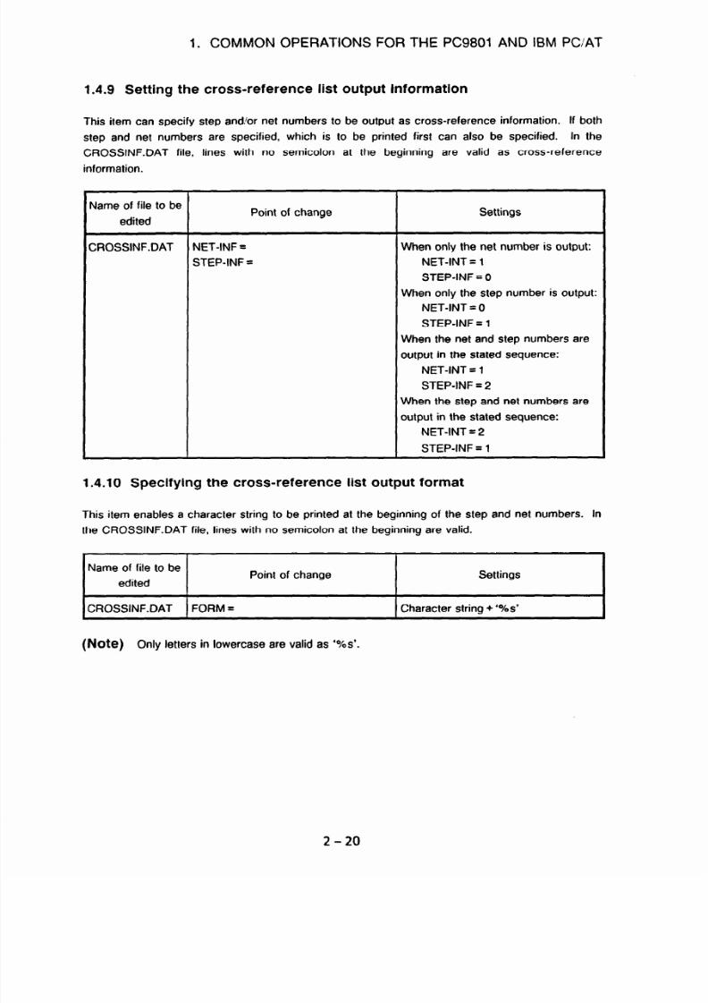
7/25/2019 FAPT Ladder for PC-Operator Manual
http://slidepdf.com/reader/full/fapt-ladder-for-pc-operator-manual 199/302
1. COMMON OPERATIONS FOR THE PC9801 AND IBM PC/AT
1.4.9 Setting the cross-reference list output information
This item can specify step and/or net numbers to be output as cross-reference information. If both
step and net numbers are specified, which is to be printed first can also be specified. In the
CROSSINF.DAT file, lines with no semicolon at the beginning are valid as cross-reference
information.
Name of file to be
edited
Point of change
Settings
CROSSINF.DAT NET-INF =
STEP-INF =
When only the net number is output:
NET-INT = 1
STEP-INF = 0
When only the step number is output:
NET-INT = 0
STEP-INF = 1
When the net and step numbers are
output in the stated sequence:
NET-INT = 1
STEP-INF = 2
When the step and net numbers are
output in the stated sequence:
NET-INT = 2
STEP-INF = 1
1.4.10 Specifying the cross-reference list output format
This item enables a character string to be printed at the beginning of the step and net numbers. In
the CROSSINF.DAT file, lines with no semicolon at the beginning are valid.
Name of file to be
edited
Point of change Settings
CROSSINF.DAT 1 FORM =
I
Character string + ‘%s’
(Note) Only letters in lowercase are valid as ‘%s’.
Z-20
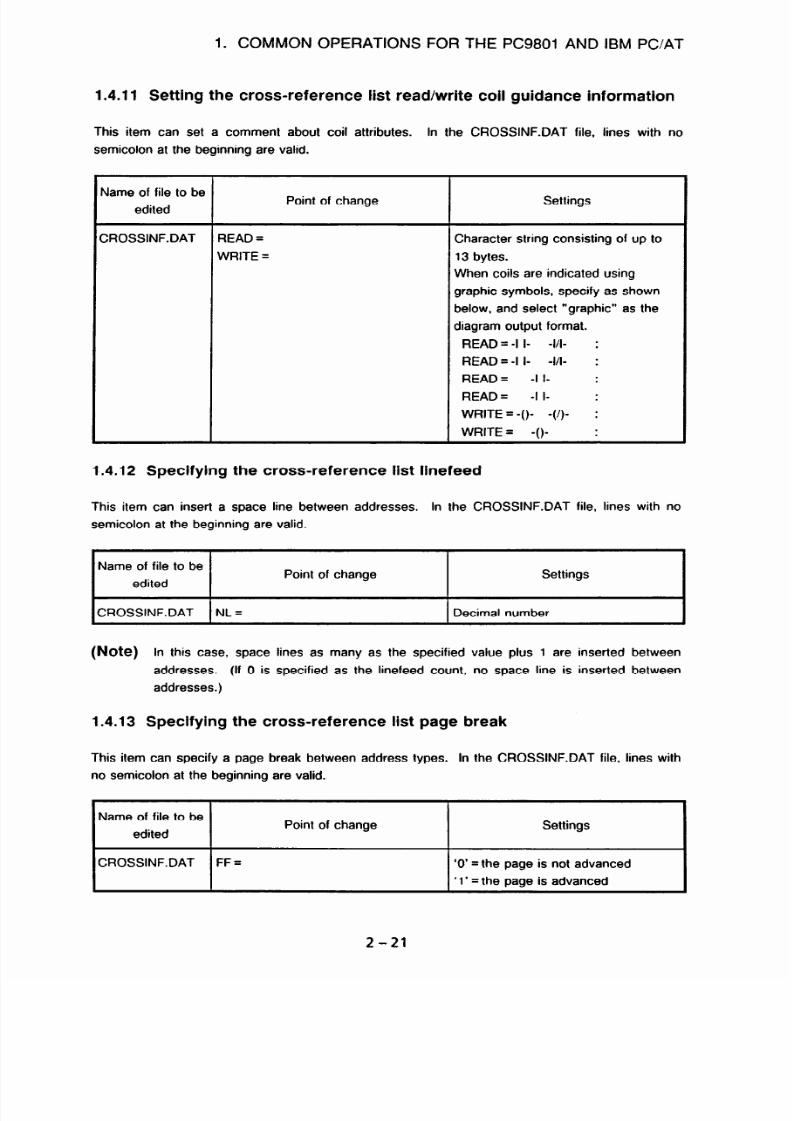
7/25/2019 FAPT Ladder for PC-Operator Manual
http://slidepdf.com/reader/full/fapt-ladder-for-pc-operator-manual 200/302
1. COMMON OPERATIONS FOR THE PC9801 AND IBM PC/AT
1.4.11 Setting the cross-reference list read/write coil guidance information
This item can set a comment about coil attributes.
In the CROSSINF.DAT file, lines with no
semicolon at the beginning are valid.
Vame of file to be
edited
Point of change
Settings
XOSSINF.DAT
READ = Character string consisting of up to
WRITE =
13 bytes.
When coils are indicated using
graphic symbols, specify as shown
below, and select “graphic” as the
diagram output format.
READ = -I I- -l/l- :
READ = -I I- -l/l-
:
READ =
-I I- :
READ =
-I I- :
WRITE = -()- -(/)-
:
WRITE = -()-
:
1.4.12 Specifying the cross-reference list linefeed
This item can insert a space line between addresses.
In the CROSSINF.DAT file, lines with no
semicolon at the beginning are valid.
Name of file to be
edited
Point of change
CROSSINF.DAT 1 NL =
I
Decimal number
(Note)
In this case, space lines as many as the specified value plus 1 are inserted between
addresses. (If 0 is specified as the linefeed count, no space line is inserted between
addresses.)
1.4.13 Specifying the cross-reference list page break
This item can specify a page break between address types. In the CROSSINF.DAT file, lines with
no semicolon at the beginning are valid.
I
ame of file to be
edited
Point of change
Settings
:ROSSINF.DAT FF = ‘0’ = the page is not advanced
‘1’ = the page is advanced
2-21

7/25/2019 FAPT Ladder for PC-Operator Manual
http://slidepdf.com/reader/full/fapt-ladder-for-pc-operator-manual 201/302
1. COMMON OPERATIONS FOR THE PC9801 AND IBM PC/AT
1.4.14 Setting the output format guidance
A desired character string can be output as guidance when the cross reference list is printed. In
the CROSSINF.DAT file, data of a line beginning with a character other than a semi-colon (;) is
valid.
File edited
I
Modifications
I
Settings
CROSSINF.DAT
GUIDE =
Desired character string of up to 19
bvtes
1.4.15 Setting the output information
As the cross reference output information, step numbers, net numbers, or both can be output.
When both step and net numbers are output, the order in which they are printed can be specified.
In the CROSSINF.DAT file, data of a line beginning with a character other than a semi-colon (;) is
valid.
File edited
CROSSINF.DAT
Modifications
NET-INF =
STEP-INF =
Settings
Only net numbers are output.
NET-INF = 1
STEP-INF = 0
Only step numbers are output.
NET-INF = 0
STEP-INF = 1
Net numbers and step numbers are
output in that order.
NET-INF = 1
STEP-INF = 2
Step numbers and net numbers are
output in that order.
NET-INF = 2
STEP-INF = 1
1.4.16 Setting the output format
A character string can be printed in front of each step or net number. In the CROSSINF.DAT file,
data of a line beginning with a character other than a semi-colon (;) is valid.
File edited
1
Modifications
I
Settings
CROSSINF.DAT
I
FORM =
I
Character string + ‘%s’
(Note)
With ‘%s,” only the lowercase letter s is valid.
2-22

7/25/2019 FAPT Ladder for PC-Operator Manual
http://slidepdf.com/reader/full/fapt-ladder-for-pc-operator-manual 202/302
1. COMMON OPERATIONS FOR THE PC9801 AND IBM PC/AT
1.4.17 Setting the read/write coil guidance
A comment about each coil attribute can be specified. In the CROSSINF.DAT file, data of a line
beginning with a character other than a semi-colon (;) is valid.
File edited
CROSSINF.DAT
Modifications
READ =
WRITE =
Settings
Character string of up to
13
bytes.
To print a coil with graphic
characters, specify as follows and
select graphic diagram output.
READ=- 1 I- -I/j-:
READ=-II- -I/I-:
READ= -1 I- :
READ= -I I- :
WRITE = -()- -(I)- :
WRITE = -()- :
(Note)
With ‘%s,’ only the lowercase letter s is valid.
1.4.18 Setting line feed
Blank lines can be inserted between the data of different addresses. In the CROSSINF.DAT file,
data of a line beginning with a character other than a semi-colon (;) is valid.
-1
File edited
Modifications Settings
CROSSINF.DAT NL =
Decimal value
(Note)
Blank lines of the specified number plus one are inserted between the data of different
address types. (If zero is specified as the line feed value, no blank lines are inserted.)
1.4.19 Setting form feed
File edited
Modifications Settings
CROSSINF.DAT FF =
‘0’ = Form feed is executed.
‘1’ = Form feed is not executed.
The printing of the data of each address type can be started on a new page.
In the
CROSSINF.DAT file, data of a line beginning with a character other than a semi-colon (;) is valid.
2-23

7/25/2019 FAPT Ladder for PC-Operator Manual
http://slidepdf.com/reader/full/fapt-ladder-for-pc-operator-manual 203/302
1. COMMON OPERATIONS FOR THE PC9801 AND IBM PC/AT
Environment settings for diagram output - example 3 (sample setting 1 of the CROSSINF.DAT file)
Sample setting of the CROSSINF.DAT file
:
GUIDEsSTEP No./NET No.
NET-INF=2
STEP-INF-1
FROM=S%s/N%s
READ--I I- -I/I- :
WRITE=-()- -(/)- :
NL=l
FF=O
;
0 Sample cross reference output
6
1 [A:YFLADDER4(SAMPLE]
***
Address
x0.0
-II-Yl+ :
x0.1
-It-+ :
YO.0
U-Q-:
RO.0
-Ii-++ :
Cross reference ***
Symbol Comment
S00045 N00009
SOOO88/NOOO20
s00050/N00010
S00077/N00029
S00045/N00009
S00009/N00003
S00022/N00010
S00047/N00019
SOOOO2/N00001
SOOO49/NOOO12
SOOO94/NOOO2
SOOO54/NOOOl2
SOO128/NOOO62
SOOOl2/NOOOO8
S00024/N00012
S00074/N00032
PAGE 1
STEP NO./NET No.
S00053/N00013
SO0059/N00015
S00256/N00098
S00014/N00009
S00033/N00015
S00079/N00035
S00082/N00017
S00065/N00017
Double writing
SOOOl5/NOOOlO
S00045/N00017
2-24

7/25/2019 FAPT Ladder for PC-Operator Manual
http://slidepdf.com/reader/full/fapt-ladder-for-pc-operator-manual 204/302
1. COMMON OPERATIONS FOR THE PC9801 AND IBM PC/AT
Environment settings for diagram output - example 4 (sample setting 2 of the CROSSINF.DAT file)
Sample setting of the CROSSINF.DAT file
GUIDE-Step
umber
NET-INF=O
STEP-INF=l
FROM=S$s
READ=read
WRITE=Write
NL-0
FF=O
:
0 Sample cross reference output
[A:YFLADDERYSAMPLE]
**
Cross reference *
PAGE 1
Step number
Address Symbol Comment
x0.0
Read
: SO0045 SO0049 SO0053 SO0082 SO0088 SO0094
x0.1
Read
:
SO0050 SO0054 SO0059 SO0065 SO0077
YO.0
Double writing
Write
:
SO0045 SO0128 SO0256
RO.0
Read
: SO0009 SO0012 SO0014 SO0015 SO0022 SO0024 SO0033 SO0045
so0047 so0074 so0079
Write
: soooo2
2-25

7/25/2019 FAPT Ladder for PC-Operator Manual
http://slidepdf.com/reader/full/fapt-ladder-for-pc-operator-manual 205/302
III. THE STEP SEQUENCE FUNCTIONS
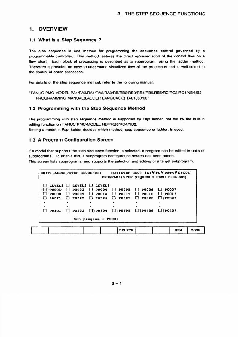
7/25/2019 FAPT Ladder for PC-Operator Manual
http://slidepdf.com/reader/full/fapt-ladder-for-pc-operator-manual 206/302
3. THE STEP SEQUENCE FUNCTIONS
1.
1.1
The
OVERVIEW
What is a Step Sequence ?
step sequence is one method for programming the sequence control governed by a
programmable controller. This method features the direct representation of the control flow on a
flow chart. Each block of processing is described as a subprogram, using the ladder method.
Therefore it provides an easy-to-understand visualized flow of the processes and is well-suited to
the control of entire processes.
For details of the step sequence method, refer to the following manual.
”
FANUC PMC-MODEL PA1 /PA3/RAl /FWWtA3/RB/RB2/RB3/RB4/RBS/RB6/RC/RC3/RC4~NB/NB2
PROGRAMMING MANUAL(LADDER LANGUAGE) B-61863/06”
1.2 Programming with the Step Sequence Method
The programming with step sequence method is supported by Fapt ladder, not but by
editing function on FANUC PMC-MODEL RB4 RB6/RC4/NB2.
Setting a model in Fapt ladder decides which method, step sequence or ladder, is used.
1.3 A Program Configuration Screen
the built-in
If a model that supports the step sequence function is selected, a program can be edited in units of
subprograms. To enable this, a subprogram configuration screen has been added.
This screen lists subprograms, and supports the selection and editing of a target subprogram.
EDIT(LADDER/STEP SEQUENCE)
RCa(STEP SEQ) [A:yFLYDATAYSFCOl]
PROGRAM:(STEP SEQUENCE DEMO PROGRAM)
0 LEVEL1 0 LEVEL2 0 LEVEL3
i0"'tiUOO1.' PO002 0 PO004
0 PO005 0 PO006 0 PO007
0 PO008 0 PO009 0 PO014
0 PO015 0 PO016 0 PO017
0 PO021 0 PO022 0 PO024
0 PO025 0 PO026 POO27
. . . . . .
. . . . . .
0 PO101 0 PO202 0 JPO304
PO405 0]PO406 PO407
Sub-program : PO001
I
DELETE
I
NEW ZOOM
3-l

7/25/2019 FAPT Ladder for PC-Operator Manual
http://slidepdf.com/reader/full/fapt-ladder-for-pc-operator-manual 207/302
3. THE STEP SEQUENCE FUNCTIONS
1.4 The Configration of a Sequence Program
A sequence program consists of the following 5 kinds of program unit;
- The 1st level of ladder
- The 2nd level of ladder
- The 3rd level of ladder
- Subprograms of ladder sequence
- Subprograms of step sequence
LEVEL 1 (LADDER)
I
LEVEL 2 (LADDER)
LEVEL 3 (LADDER)
Sub Program Pl (Step Sequence)
I
Sub Program P2 (LADDER)
1
I
ub Program P3 (LADDER)
I
Sub Program Pn (Step Sequence)
3-2

7/25/2019 FAPT Ladder for PC-Operator Manual
http://slidepdf.com/reader/full/fapt-ladder-for-pc-operator-manual 208/302
3. THE STEP SEQUENCE FUNCTIONS
1.5 Data Flow
-PC9801*IBWPC/AT
Source program
Ladder 1st level
Mnemonic
conversion
Ladder 2nd level -
Ladder 3rd level -
Subprogram Pl
7
Subprogram P2
Compilation/Decompilation
Object code
Mnemonic program
A mnemonic program without
step sequence
I
OM format program
I
L
t
'71
Input/Output Input/Output Input/Output
Transfer data Floppy cassette
Memory card
4
4 4
- RS232C
- Handy File.
- FLOPPY CASSETTE ADAPTER
-
Memory card
-CNC
I
v + v
1)
[PMCI
2) II/O1
3)[HOST]
1) [PMCI
2) I I/O1
3)[FDCAS]
1)
IPMCI
2) II/O1
33) [MCARD]
(Boot process also can
read the memory card)
The operation of soft key when input/output
3-3

7/25/2019 FAPT Ladder for PC-Operator Manual
http://slidepdf.com/reader/full/fapt-ladder-for-pc-operator-manual 209/302
3. THE STEP SEQUENCE FUNCTIONS
2. SETTING A MODEL
2.1 Operation
(1)
(2)
Starting FAPT LADDER
At the MS-DOS prompt, key in FLADDER.
Displaying the initial screen
Once the system edition, copyright. and other information have been displayed, press any key.
FAPT LADDER
AOEB-92014502#EN
Ver 08.0 1994.07.22
Copyright (C) 1991 FANUC LTD
END ? (Y:END, 0THER:RESUME MENU)
(3)
Displaying the main menu
When the menu screen is displayed as shown below, press the < F7 > (SETUP) key.
MAIN MENU
Fl KEY :
F2 KEY :
F3 KEY :
F4 KEY :
F5 KEY
:
F6 KEY :
F7 KEY :
FE KEY :
F9 KEY :
FlO KEY :
[A:YFLYDATAYSFCY 1
EDIT
COMPILE
DISCOMPILE
LINK
I/D
SETUP
MNEMONIC EDIT
UTILITY
END
EDIT
COMPIL DISCPL
I/D
SETUP UTILTY END
3-4

7/25/2019 FAPT Ladder for PC-Operator Manual
http://slidepdf.com/reader/full/fapt-ladder-for-pc-operator-manual 210/302
3. THE STEP SEQUENCE FUNCTIONS
(4) Setting the PMC model
To use the step sequence function, select PMC-XXX(STEP SEQ or PMC-RB6 or PMC-NB2)
(model which supports the step sequence function) from the listed models.
SETUP RCQ(STEP SEQ)
PMC-RAl
PMC-RA2
.
.
PMC-RB4 (STEP SEQ)
.
.
* PMC-RC4 (STEP SEQ)
.
.
Select by cursor and hit [Enter] key.
COPY
I
I
END
3-5

7/25/2019 FAPT Ladder for PC-Operator Manual
http://slidepdf.com/reader/full/fapt-ladder-for-pc-operator-manual 211/302
3. THE STEP SEQUENCE FUNCTIONS
3. EDITING
This section describes how to create a step sequence program.
3.1
Basic Operation
(1) Displaying the main menu
Press the < Fl > (EDIT) key.
MAIN MENU
[A:YFLYDATAYSFC%
Fl KEY :
F2 KEY :
F3 KEY :
F4 KEY :
F5 KEY :
F6 KEY :
F7 KEY :
F8 KEY :
F9 KEY :
FlO KEY :
1
EDIT
COMPILE
DISCOMPILE
LINK
I/O
SETUP
MNEMONIC EDIT
UTILITY
END
EDIT COMPIL DISCPL
I/O
SETUP
UTILTY END
(2)
Selecting the program to be edited
Enter the name of the source program to be edited.
SELECT SOURCE PROGRAM Rc4(sTEP SEQ) [A:YFLYDATAYSFC%
1
SOURCE PROGRAM NAME
:
TEST
EXEC I END
Press the c Fl key. The screen changes, depending on the program to be entered.
1)
2)
3)
If a new program name is specified:
The model setting screen is displayed. Re-confirm the selected model.
Then, the edit menu is displayed.
If the specified name is that of a program created for a model which differs from the
selected model:
The selected model is automatically changed according to the specified program. Then,
the edit menu is displayed.
If the specified name is that of a program created for the selected model:
The edit menu is displayed.
3-6

7/25/2019 FAPT Ladder for PC-Operator Manual
http://slidepdf.com/reader/full/fapt-ladder-for-pc-operator-manual 212/302
(3)
3. THE STEP SEQUENCE FUNCTIONS
To return to the main menu, press the < FlO> or < ESC> key. As the program name, enter
up to eight alphanumeric characters, without an extension.
Displaying the editing menu
Press the < F2 > (LADDER/STEP SEQUNCE) key.
EDIT
RCI(STEP SEQ) [A: YFL~DATAYsFcY 1
Fl KEY : TITLE
F2 KEY :
LADDER / STEP SEQUENCE
F3 KEY : SYMBOL h COMMNET
F4 KEY :
MESSAGE
F5 KEY
: I/O
MODULE
F6 KEY :
SYSTEM PARAMETER
FlO KEY : END
1 TITLE ILADSFC ISYMBOL IMESSAG IMODULEISYSPRM 1
I
I
I I
I
I I
I
I END
I
(4)
Subprogram configuration screen
The subprogram configuration screen is displayed as shown below:
EDIT(LADDER/STEP SEQUENCE)
RC4(STEP SEQ) [A:YFLyDATAYSFCOl]
PROGRAM:(STEP SEQUENCE DEMO PROGRAM)
0 LEVEL1 0 LEVEL2 0 LEVEL3
.
. .
‘m;i’J)@ti$., 0 PO002 0 PO004 0 PO005 0 PO006 0 PO007
0 PO008 0 PO009 0 PO014 0 PO015 0 PO016 0 PO017
0 PO021 0 PO022 0 PO024 0 PO025 0 PO026 POO27
.
. . .
.
.
. . . .
.
.
0
PO101 0 PO202 PO304 PO405 PO406 PO407
Sub-program
:
PO001
I
I I I
DELETE
I
NEW ZOOM
3-7

7/25/2019 FAPT Ladder for PC-Operator Manual
http://slidepdf.com/reader/full/fapt-ladder-for-pc-operator-manual 213/302
3.
THE STEP SEQUENCE FUNCTIONS
Note 1) The 3rd ladder level can be omitted.
Note 2)
If the [ZOOM] key was used to nest a program to a certain depth, and if the
subprogram configuration screen is displayed upon a single press of the [MAIN] key,
the editing of the subprograms for which the [ZOOM] key was pressed is suspended.
Such subprograms are marked with A].
(5)
Step sequence diagram
Position the cursor to a program marked with 01, then press the [ZOOM] or <RET> key.
The step sequence editing screen is displayed as shown below:
C
DIT(LADDER/STEP SEQUENCE) Rc4(sTEP SEQ) [A:YFLYDATAYSFC~~]
PROGRAM:(STEP SEQUENCE DEMO PROGRAM)
,.. .)))):.
.,:,:
(..>:‘t’:i
J@J$,
7
s3
cl Sll 0 s13
s21 cl s31
Note 1) The current position of the cursor on the screen is indicated.
The entire screen consists of 32 elements across the screen
and 64 elements from top to bottom. The cursor is positioned to
any element on the screen.
4 (Note 1)
3-8

7/25/2019 FAPT Ladder for PC-Operator Manual
http://slidepdf.com/reader/full/fapt-ladder-for-pc-operator-manual 214/302
3. THE STEP SEQUENCE FUNCTIONS
3.2 Creating a Step Sequence
3.2.1 Creating a subprogram of the step sequence
EDIT(LADDER/STEP SEQUENCE) RCI(STEP
SEQ)
[A:~FL~DATAfSFCOl]
PROGRAM:(STEP SEQUENCE DEMO PROGRAM)
0 LEVEL1 0 LEVEL2 0 LEVEL3
;/$;;-'i:&jflQ~ n,... PO004 PO005 PO006 PO007
.: ........
]POOO2 0 0 0 0
0 PO008 0 PO009 0 PO014 0 PO015 0 PO016 0 PO017
0 ]POO21 0 PO022 0 PO024 0 PO025 0 PO026 POO27
.
.
.
.
.
.
.
.
.
.
.
I
DELETE NEW ZOOM
Following keys are useful in this screen.
Function key
Other keys
[ DELETE] : Deleting a subprogram [ROLL UP]
: Displaying previous screen
[NEW ] :
Creating a new subprogram [ROLL DOWN] : Displaying next screen
[ZOOM ] :
Modifying a subprogram
Meaning of display
EDIT(LADDER/STEP SEQUENCE) RC4(STEP SEQ) [A:%FLYDATAYSFCOl]
Edit
: FAPT LADDER editing screen
(LADDER/STEP SEQUENCE) : The list screen of subprogram
PMC-RC4 (STEP SEQ) : Setting a model
[A: Y FL.. : Current directory
I
PROGRAM:(STEP SEQUENCE DEMO PROGRAM)
PROGRAM
: Remarks which is one of the title data
aLEVEL EVEL2 OLEVEL3
I
LEVEL1 : The 1st level of ladder
LEVEL2 :
The 2nd level of ladder
LEVEL3 : The 3rd level of ladder
(In case of PMC-RC4 the 3rd ladder level can be omitted, in case of PMCRB4
the 3rd ladder level does not exist.)
0 PO001 POOO2 0 PO004 0 PO005 0 PO006 0 PO007
Cl -: a subprogram of the ladder
01
: a subprogram of the step sequence
3-9

7/25/2019 FAPT Ladder for PC-Operator Manual
http://slidepdf.com/reader/full/fapt-ladder-for-pc-operator-manual 215/302
3. THE STEP SEQUENCE FUNCTIONS
(1) Creating a new subprogram
- Press the [NEW] key.
New program
name ? m
- Enter the number of the subprogram to be created (P200, for example).
- Press the [F2 ] key.
(2) Modifying a subprogram
- Key in the number of the subprogram to be modified (P200, for example), then press the
[ZOOM] or <RET> key.
Alternatively, position the cursor to P200 then press the
[ZOOM] or <RET > key.
- If a subprogram number marked with A ] (P21, for example) is selected, the following
message is displayed:
Editing this subprogram is not completed.
Continue to select it 7 (Yes/No)
[Yl 1
To continue the editing session using the results obtained from suspended previous editing
session, press the < RET > key. To cancel the results of the previous editing session and edit
the subprogram from its original state, enter < N >.
3.2.2 Creating a step sequence program
The basics and configuration of the step sequence are described in the following document:
“FANUC PMC-MODEL RB4/RC4 Supplementary Description of Programming (Ladder Language)
B-61 863EI05-3”
On the step sequence screen, different soft keys are displayed, depending on the position of the
cursor.
When the cursor is on the step line, following softkey menu is displayed.
I
. .I
cl] s2
‘:ti;:ili;;$;$
I
0 s20
+- La
cl s30
cl
101
1
I
-+ JHP
FUNC
CHK ZOOM
3-10
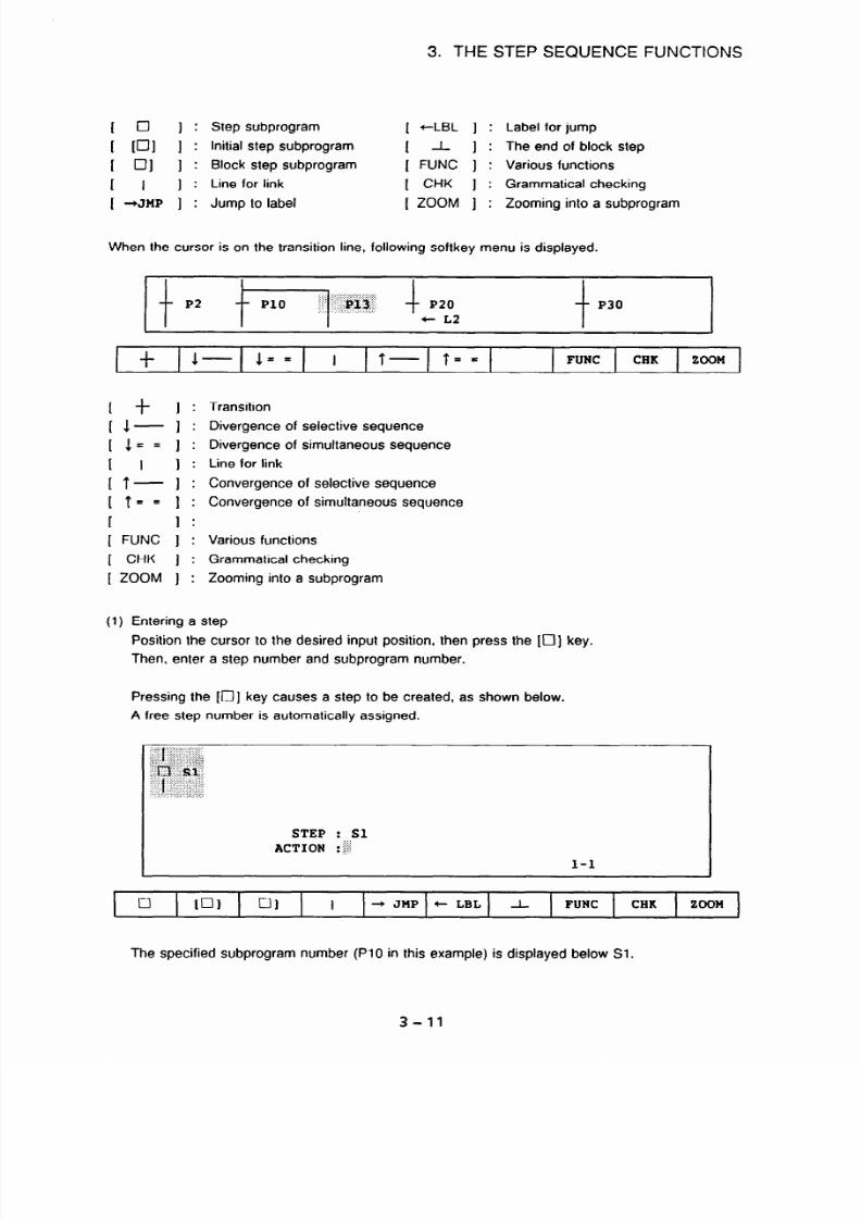
7/25/2019 FAPT Ladder for PC-Operator Manual
http://slidepdf.com/reader/full/fapt-ladder-for-pc-operator-manual 216/302
3. THE STEP SEQUENCE FUNCTIONS
1
0
I:
Step subprogram
[ tLBL ] :
1
UJI 1:
Initial step subprogram
I A- I:
[ 01 I:
Block step subprogram ( FUNC ] :
1 I
I :
Line for link [ CHK ] :
[ +JMP ] : Jump to label
( ZOOM ] :
Label for jump
The end of block step
Various functions
Grammatical checking
Zooming into a subprogram
When the cursor is on the transition line, following softkey menu is displayed.
FUNC CHK
ZOOM
[ t I:
I l- I :
[ l== 1:
I
I I:
I t- I :
[t== 1:
[
I :
[ FUNC ] :
[ CHK ] :
[ ZOOM ] :
Transition
Divergence of selective sequence
Divergence of simultaneous sequence
Line for link
Convergence of selective sequence
Convergence of simultaneous sequence
Various functions
Grammatical checking
Zooming into a subprogram
(1)
Entering a step
Position the cursor to the desired input position, then press the [Cl] key.
Then, enter a step number and subprogram number.
Pressing the [n] key causes a step to be created, as shown below.
A free step number is automatically assigned.
iii;‘iij,t~.:.:.~.:.Y::“:
~~~
.;:.S
$5
:::: ,:i-i_._:~:”
..,.:.._
STEP : Sl
.
ACTION :?
l-1
I
- JMP +LBL -L FUNC
CHK ZOOM
The specified subprogram number (PlO in this example) is displayed below Sl.
3-11

7/25/2019 FAPT Ladder for PC-Operator Manual
http://slidepdf.com/reader/full/fapt-ladder-for-pc-operator-manual 217/302
3. THE STEP SEQUENCE FUNCTIONS
(2)
STEP : 81
ACTION : PlO
l-l
To change the step number, press the <RET> key to position the character cursor ” .?’ on
STEP and use the [BS] key to change the number.
.:$:f B~~:.:~
~~~~:
T;f;y . . :.:.::.:
,,i;;,;i;y:::::::::>:..
,... .:.:::::::::
)::::::, ::::“::...:.:.:.:.:.~..~:
.:
. : . :. : , : . :. : : . ’
STEP : Slg
ACTION : PlO
l-l
Entering a transition
Position the cursor to the desired input position, then press the [ + ] key.
Enter a subprogram number
Press the
[ + ]
key.
ACTION : ‘.:$
l-2
FUN
CHR
ZOOM
Enter a subprogram number.
I
o)i ,:ilFI:t:~:~::s:‘~~~~~~
.\:
.
:..:‘::p::; ;I:,. ,.:
3
:
+
.::.::.
:.:~~~~~
. :
j::+ ::~.~:~,~.~::~~~:~,:::~.:,~,.~:i.~
.‘::.‘; :........, ..:.:“::>,. .>
,:, . . ;,.;..
: : . .i.;:; 1::: ..:
.:.I,., :..
ACTION : $100
l-2
3-12

7/25/2019 FAPT Ladder for PC-Operator Manual
http://slidepdf.com/reader/full/fapt-ladder-for-pc-operator-manual 218/302
3. THE STEP SEQUENCE FUNCTIONS
(3)
Divergence of selective sequence
Position the cursor to the desired input position and press the [ 1 --_I key.
FUNC CHR
ZOOM
Position the cursor to the desired input position and press the [ 1 -_I key.
I I
(4)
Convergence of selective sequence
Position the cursor to the desired input position and press the [ f -] key.
ACTION : PlO&
2-4
1 +.
I+_Il=zl
1 It-_lt__l
FUNC CHK
ZOOM
3-13

7/25/2019 FAPT Ladder for PC-Operator Manual
http://slidepdf.com/reader/full/fapt-ladder-for-pc-operator-manual 219/302
x
g
u
u
z
I
I
c-i--
II
-
I
- -
z
u
Yz
II
t-j---
I
I
-- -t-

7/25/2019 FAPT Ladder for PC-Operator Manual
http://slidepdf.com/reader/full/fapt-ladder-for-pc-operator-manual 220/302
3. THE STEP SEQUENCE FUNCTIONS
Specifying a label for jump destination
Position the cursor to the desired input position (step line), then press the [- LBL] key.
Then, enter a label name.
Press the [+ LBL] key.
I
+ JMP +LBL 1
FUN HR
ZOOM
LABEL : Ll@;
l-l
Enter a label name.
STEP : Sl
ACTION : PlO
l-l
3-15

7/25/2019 FAPT Ladder for PC-Operator Manual
http://slidepdf.com/reader/full/fapt-ladder-for-pc-operator-manual 221/302
3. THE STEP SEQUENCE FUNCTIONS
(8) Specifying a label jump
Position the cursor to the desired input position (step line), then press the [+ JMP] key.
Then, enter a label name.
Press the [+ JMP) key.
A...
LEBEL : $$
2-3
I
+ JMP + LBL FUNC
CHK
200?4
Enter a label name.
+-
L10
101 s1
I
PlOO
PlOO
f-r
::,::'.i,jjj.~:~:i'i.li~:~;i:
:;.;_ ,;::;.;<.:.y
, 2
&A:itxiO
t
;I:;:-"'i'i.:.:?.i':...
., .:::::i.:y,
.
:,,;:>,:
. ‘.:.:...:.:.:;.:.:.:.:.:.:
:~~:~.~:~::..‘.::‘:::::~::::~:~:~:::::
PlOO
LEBEL : Llfi:
2-3
3-16

7/25/2019 FAPT Ladder for PC-Operator Manual
http://slidepdf.com/reader/full/fapt-ladder-for-pc-operator-manual 222/302
3. THE STEP SEQUENCE FUNCTIONS
(9) Deleting an element
Position the cursor to the element to be deleted, then press the [DEL] key.
I
elect the element by the <DEL> key and press the <return> key
In the example shown above, two figures (elements) of a selective branch and transition are
selected. Specify the element to be deleted with the narrow cursor, displayed in reverse
video. To position the cursor displayed in reverse video, press the [DEL] key. To restore the
state shown above, press the (ESC] key.
If the [RETURN] key is pressed in the state shown above, the selective branch is deleted and
the following screen is displayed:
3-17
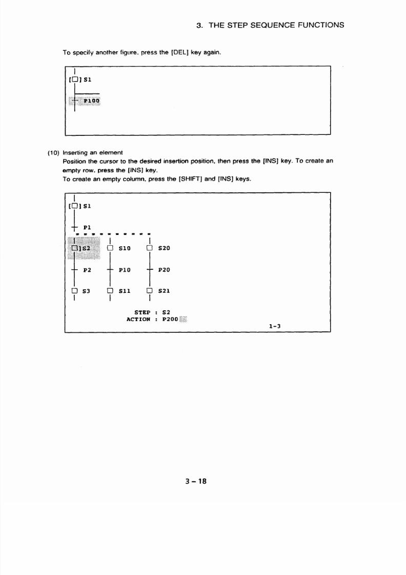
7/25/2019 FAPT Ladder for PC-Operator Manual
http://slidepdf.com/reader/full/fapt-ladder-for-pc-operator-manual 223/302
3. THE STEP SEQUENCE FUNCTIONS
To specify another figure, press the [DEL] key again.
I
I01 Sl
.
.k
..,.......
.I . . . . . .
>:..A .,
.:..
:::.. :
‘:~l;;;i;~g~.
.
Inserting an element
Position the cursor to the desired insertion position, then press the [INS] key. To create an
mpty row, press the [INS] key.
o create an empty column, press the [SHIFT] and [INS] keys.
STEP : S2
ACTION :
p 2 0 0 @$
l-3
3-18

7/25/2019 FAPT Ladder for PC-Operator Manual
http://slidepdf.com/reader/full/fapt-ladder-for-pc-operator-manual 224/302
3. THE STEP SEQUENCE FUNCTIONS
Press the (INS] key.
l-3
Press the [SHIFT] and [INS] key.
IO1 Sl
c
l
Cl Sll
cl s21
I
I
STEP : S2
ACTION : PlO2
l-3
3-19

7/25/2019 FAPT Ladder for PC-Operator Manual
http://slidepdf.com/reader/full/fapt-ladder-for-pc-operator-manual 225/302
3. THE STEP SEQUENCE FUNCTIONS
(11) Search
q;;..“;.===== =,
..::::. ...:j:::ji(ij:j.
..;:.I‘I:;:‘:‘: :.:.::: jj ::..:.
1
g$j::$i:.;.‘:“‘l:li:-J
SlO
;;. t
Cl s20
(,,
,..,::,,...
_..
:)>>::..,:: .::.:5:":
.
:.
.."."..."~>;.>:.,.::.:.>
: ?....
.,
.i..
Pl
Pll
t
P21
T2
cl SlO Cl s20
I
I
If the [F8] (FUNC) key is pressed in the state shown above, a pop-up menu is displayed as
shown below:
Fl Search
F2 Copy
F3 Move
F4 Main
S
List
Y3
cl Sll cl s21
I
I
Press the [Fl] (Search) key. A pop-up menu is displayed, as shown below:
t
Pl
Fl
F2
F3
F4
F5
F6
F7
Step
Action
Label
symbol
Position
Top
Bottom
3-20

7/25/2019 FAPT Ladder for PC-Operator Manual
http://slidepdf.com/reader/full/fapt-ladder-for-pc-operator-manual 226/302
3. THE STEP SEQUENCE FUNCTIONS
Then, press the (Fl] (Step) key. Another pop-up menu is displayed, as shown below:
Enter the step number to be searched for (S20, for example), then press the < RET > key.
The system starts searching through the part subsequent to the cursor.
Copying or moving an element
Press the [F8] (FUNC) key.
t
Pl
3-21

7/25/2019 FAPT Ladder for PC-Operator Manual
http://slidepdf.com/reader/full/fapt-ladder-for-pc-operator-manual 227/302
3. THE STEP SEQUENCE FUNCTIONS
When the [F8) (FUNC) key is pressed, a pop-up menu is displayed as shown below:
Fl Search
F2 Copy
F3 Move
F4 mAin
FS List
Press the [F2) (Copy) key. The system prompts the operator to enter a start point.
ACTION
:
Specify Start position
l-2
Position the cursor to the desired start point (position 2-3 in the example shown below), then
press the < RET > key. The system prompts the operator to enter the end point.
It
Pl
.gi.lj?“
.::;;;y;: :,:.:
i +
.>.::.::::::
,.
:: ‘:: :::::.::::::
. ._
,(,.:.:.,.:
S2
;;::,&T .:*:...
..:.:.:..q:‘-: IJ s20
:..:.. ./\. : , .,..
.j,..;.
:::.y::::::: ,..:.
::,:;.: .,::.:,,..‘. ::.;
. ,.. .‘.‘.,i::::.::::::.;::.:.+:
Pl
Pll
+
P21
I
ACTION
:
Specify End position
2-3
3-22

7/25/2019 FAPT Ladder for PC-Operator Manual
http://slidepdf.com/reader/full/fapt-ladder-for-pc-operator-manual 228/302
3.
THE STEP SEQUENCE FUNCTIONS
Position the cursor to the desired end point (position 3-4 in the example shown below), then
press the < RET > key. The system prompts the operator to specify a copy destination.
:z’:’ J::”
S2
;;; ~~~
:~~~~~~:~~~~
i c
I:::iliii:ll:i:li#i:~,::,:~:~:~:~~:
:::‘.zyi.~.I_:~~I:I:I:i.i:~~~~~~~~~:~~:~:,,~,~~
:....:.:...:>:...:.:i\:.:
. ,. . ..\..\\:. ._..,,, ,,,,.,,,
.,i,i:I:I:I:I’I:i:I’I:I:i::I:i6:i:
:j;j;y:~~:~,~:~:~:~:~:~:~::::::.,.~~.~::i:~.~r~:~~:::~~:..~,:;:;:y:;:~:..:::::::::.:.:.:..:.:
:::.:;;:::~~~~~::5::iili:~Bi:~:~~:::::~:
+
:.:_.,..:.::;:::::::
p1 C.“
.;,,.,,::I:~;~~ws~;~~~:;:,‘::.;..:,,
. ‘.y,,:...::::z::i,:,
.,.,.,...
I:::.::‘:
.:.:..,:.:.:.:.:.:.:,,
.:.:.:.:.:.:.:.:.:i(.:.,.;..
,;:;i:@ :qgg
L.............
..
:.:.::::::::::::::::::::::::
.:.: ,.(.l,L..i_
:.:.....::.“:f+;~::‘:.:.:.::::::.:.:::.:.:.:.:....:,.
::;:y:i:::;:::.,.:,:::,:::::::z:i::
..,,‘,):‘,::,:,...:,.y:::,.,
I
ACTION
:
Specify End position
3-4
Position the cursor to the desired copy destination (position 4-3 in the example shown below),
then press the < RET > key. The specified part is copied.
t
Pl
ACTION
:
PlOO
When a part is copied,
- The S address is not copied. Assign a free number.
- The P address is copied. If required, change the address.
3-23

7/25/2019 FAPT Ladder for PC-Operator Manual
http://slidepdf.com/reader/full/fapt-ladder-for-pc-operator-manual 229/302
3. THE STEP SEQUENCE FUNCTIONS
(13)
Returning from the ZOOM destination to the program configuration screen (MAIN).
To return to the program configuration screen, displayed when editing was started, follow the
procedure below. The system assumes that the editing of the step sequence subprogram,
from which the [ZOOM] key was pressed, is suspended.
The edited subprogram is not saved in the source program file.
Press the [F8] (FUNC) key.
$1::”
_....\\..
::;;g:: .‘:;:::y:y:;:~::
_, .,. . . ,.,_
$Q;”
.’
.‘.Y .* 1
$.:‘rii:”
0
SlO
Cl
s20
~~~~ tpll i
P21
After pressing the [F8] (FUNC) key
F3 Move
F4
mAin
F5 List
rfter pressing the (F4] (MAIN) key
EDIT(LADDER/STEP SEQUENCE) R~~(~TEP SEQ) [A:YFLYDATAYSFC~~)
PROGRAM:(STEP SEQUENCE DEMO PROGRAM)
LEVEL1 LEVEL2
LEVEL3
$@,iip;& $ 0
~0002
0
PO004
0
pooo5 0 poooe
0 p(JoO7
0008 0 PO009
0 PO014
0 PO015 PO016
0 PO017
A]~0021 0 PO022
0 PO024
0 PO025 0 PO026
POO27
. . .
. . .
.
0 ~0101 b
.
. .
~0202
PO304
0JPO405 c]]PO406
&PO407
3-24

7/25/2019 FAPT Ladder for PC-Operator Manual
http://slidepdf.com/reader/full/fapt-ladder-for-pc-operator-manual 230/302
3. THE STEP SEQUENCE FUNCTIONS
If the subprogram whose previous editing session was suspended (marked with A]) is
selected again for editing, the following message is displayed:
Editing this subprogram is not completed.
Continue to select it ? (Yes/No
1 [Yl
(14)
To continue the previous editing session, press the [RET] key.
Otherwise, enter N. (The result of the previous editing session is cancelled.)
LIST
The list of subprograms referenced by the stepsequence subprogram that is currently being
edited is displayed.
Press the (F8] (FUNC) key.
i_i:.::~~.::;:.; 7 = = = = j =
.:::::.:::::ii:‘:I:‘i8iiiiiiii
:~~~~~~~ Cl SlO
cl s20
.
.I ‘+
.
.I’.‘..
.:.:,:.:::.:::.::::::~:;::~::,:
‘.‘.:‘::.‘.‘.::.:.;.:
:::,t :: i;::‘i:::i::i::_:~::.~
Pl Pll
t
P21
After pressing the [F8] (FUNC) key
t
Pl
=II=I=t=III
Fl Search
F2 Copy
F3 Move
F4 mAin
F5 List
I
I
After pressing the [F4] (LIST) key
EDIT(LADDER/STEP SEQUENCE)
R~~(~TEP SEQ) [A:YFLYDATAYSFCO~]
PROGRAM:(STEP SEQUENCE DEMO PROGRAM)
OJP200
0 PO008 0 PO009 0
PO014 0 PO015 0 PO016 0 PO017
0 PO021 0 PO022 0
PO024 PO025 0 PO026 POO27
I
MAIN CHANGE
ZOOM
3-25

7/25/2019 FAPT Ladder for PC-Operator Manual
http://slidepdf.com/reader/full/fapt-ladder-for-pc-operator-manual 231/302
3. THE STEP SEQUENCE FUNCTIONS
Following keys are useful in this screen.
Function key
Other keys
[ MAIN
] :Displaying the subprogram
[ROLL UP]
: Displaying previous screen
configuration screen [ROLL DOWN] : Displaying next screen
[ CHANGE ] :Creating a new subprogram
[ ZOOM
] :Modifying a subprogram
Screen display
I
P200
I
The subprogram which is being edited is displayed. If the [ZOOM] key is pressed to nest the
program to a certain depth, the subprogram numbers are arranged from the left in the order in
which they are nested.
The subprogram for which the [ZOOM] key was pressed first is
displayed at the left end.
( 0 PO008 0 PO009 [I3 PO014 0 PO015 0 PO016 O017
Subprograms referenced by the subprogram that is currently being edited are listed with the
following mark: :
cl :
Ladder subprogram
cl] : Step sequence subprogram
(15)Checking the syntax
Press the [CHK] key.
t
Pl
.;:.(.‘:.:.:.:.~:.~::::::::::,
gqc.
:.::.:::,:::I:.‘:,:,::::....:.
j:,..., :.:7 ./.
;-,~:il~:~:~~
,.,; ::~...,.,.:
I
0
s
1
0
0 s20
:,t-ll~~ t
Pll P21
3-26

7/25/2019 FAPT Ladder for PC-Operator Manual
http://slidepdf.com/reader/full/fapt-ladder-for-pc-operator-manual 232/302
3. THE STEP SEQUENCE FUNCTIONS
If the step sequence is satisfactory, the following message is displayed:
.;.“..::..:.::;: .:
."f:
.. ....................
... . ... . .....
.....
.:.:.::
..?..): ..: ..:.:.:::: .
: : : >: :
..................
~~~~~~~~
slo
.:.::.:..:.
.. .:
“:.:‘:‘:j::::::::
:>::z: .::i;i::,i:i::llii;ili:iliiilcy;
2;:s:: ............
...
. :.:.
. >
...................
...................
t t
Pl
Pll
Check completed
I
If the step sequence is invalid, the following message is displayed:
+
Pl + ~11
[Chart Sequence
error
1
I
I
I
I
(16)Modifying a subprogram (ZOOM)
Press the [ZOOM] key.
~~~~~~~l,;~~.~==== =
::::::::;:;:::::::;:::.:,:g:>::;:;:i:
“~~:~~~~di
0 SlO
:; t
cl s20
. ::.:i”.:.:.:::::+. 2;.
,.,,,,,;,:.,....
,:::.::.::
: ;$ jjj,::jjj:,:~~g::j:~::
Pl
Pll
t
P21
Y2
cl SlO Cl
s20
I I
3 - 27

7/25/2019 FAPT Ladder for PC-Operator Manual
http://slidepdf.com/reader/full/fapt-ladder-for-pc-operator-manual 233/302
When the [ZOOM] key is pressed, the figure pointed by cursor decides the type of subprogram
which is to be edited.
L
Figure
Meaning of the figure
Subprogram to be edited
0
Step sequence subprogram
Ladder subprogram
101
Initial step sequence subprogram Ladder subprogram
01
block step sequence subprogram
Step S8qU8nC8 subprogram
t
Transition
Ladder subprogram
3. THE STEP SEQUENCE FUNCTIONS
(17)End of modifying
Press the
[ESC]
key.
Fl Save update) h quit
F2 Quit
F3 Edit
F4 Rename,
save h quit
F5 Optimize
Menus
Menu
I
Editing
I
Result of editing
I
Display
Save
I
nd
I
ptimized
Quit
Edit
Rename
optimize
End
Continue
End
Continue
Discarded
Continued
Updated
Optimized and continued
-
Not optimized
Optimized
Optimized
3-28

7/25/2019 FAPT Ladder for PC-Operator Manual
http://slidepdf.com/reader/full/fapt-ladder-for-pc-operator-manual 234/302
L
C
L
n
a

7/25/2019 FAPT Ladder for PC-Operator Manual
http://slidepdf.com/reader/full/fapt-ladder-for-pc-operator-manual 235/302
APPENDIX 1 DATA TRANSFER CABLES
APPENDIX 1 DATA TRANSFER CABLES
Use the cables below to transfer data from a PC to a CNC, ROM writer (FA writer or PMC writer),
or P-G (P-G Mark II or P-G Mate).
1. For PC9801
PC980 1
25pin male
connector
On-line cable
25pin male
connector
CNC, ROM writer, or P-G
2. For IBM PC/AT
IBM PC/AT
g-pin female
connector
IBM PC/AT cable
25pin male
connector
25pin female
connector
On-line cable
II
25-pin male
connector
CNC, ROM writer, or P-G
3. For IBM PS/2
IBM PSI2
25-pin female
connector
IBM PS/2 cable
25-pin male
connector
25-pin female
connector
On-line cable
n
t
25-pin male
connector
1
CNC, ROM writer, or P-G
Al-l

7/25/2019 FAPT Ladder for PC-Operator Manual
http://slidepdf.com/reader/full/fapt-ladder-for-pc-operator-manual 236/302
APPENDIX 1 DATA TRANSFER CABLES
0 On-line cable (AOSB-0031-K8Ol/K802)
SD
RD
RS
25dn male
connector
cs
ER
DR
CD
SG
FG
IBM PC/AT cable
CD
RD
SD
g-Din female
connector
ER
SG
DR
RS
cs
Cl
2
2
4
4
I 5
I
5
ZI E
7
7
1
1
1
8
2
3
3
2
4 20
5
7
6
6
7
4
8
5
9
22
SD
RD
RS
25-pin male
cs
connector
ER
DR
CD
SG
FG
CD
RD
SD
25-pin female
ER connector
SG
DR
RS
cs
Cl
Al-2
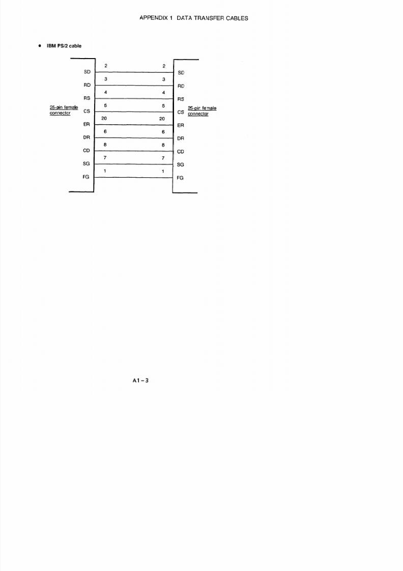
7/25/2019 FAPT Ladder for PC-Operator Manual
http://slidepdf.com/reader/full/fapt-ladder-for-pc-operator-manual 237/302
AP
b

7/25/2019 FAPT Ladder for PC-Operator Manual
http://slidepdf.com/reader/full/fapt-ladder-for-pc-operator-manual 238/302
APPENDIX 2 FUNCTION FOR OPERATING
THE PMC-UM WITH RAM
APPENDIX 2 FUNCTION FOR OPERATING THE PMC-L/M WITH
RAM
1. GENERAL
This appendix describes the procedure for operating the PMC-L using built-in RAM or the PMC-M
using the optional RAM board. It also describes related notes.
2.
(1)
(2)
HARDWARE CONFIGURATION
PMC-L
No extra hardware is needed.
The PMC-L is operated with ROM only when the PMC-L is provided with the ROM and without
the Ladder Edit Cassette (printed circuit board).
PMC-M
The optional RAM board is necessary.
It is also necessary to mount the Ladder Edit Cassette
or to mount ROMs for the PMC-M on the ROM sockets, OEl and OE2, on the memory board.
Mount the PMC-M ROMs on the sockets as shown below.
ROM number Socket location on the memory card
OF1
-_)
OEl
OF1
+
OEl
Memory card
(A16B-1212-0210)
(Note 1)
(Note 2)
When the PMC-M is provided with the ROM board, it is operated with ROM whether
the Ladder Edit Cassette is mounted or not.
When a ladder program is modified using the Ladder Edit Cassette on the PMC-M
provided with the ROM board, the PMC-M executes the original ladder program stored
in the ROM board, and the modified ladder program is displayed on the screen with the
DGNOS ladder diagram display function. The program being executed and the
program being displayed are different.
A2-1

7/25/2019 FAPT Ladder for PC-Operator Manual
http://slidepdf.com/reader/full/fapt-ladder-for-pc-operator-manual 239/302
APPENDIX 2 FUNCTION FOR OPERATING
THE PMC-L/M WITH RAM
3. RAM OPERATION
Follow the flowchart shown below to perform the RAM operation.
(1) PMC-L
Contents of the
backup RAM
Yes
No
Is the EPROM
Parameter for
displaying the
PMC load select
Yes
screen
=I pk
(see Section 4)
(Note) Ladder programs
stored in the EPROM are
copied to the RAM.
A2-2

7/25/2019 FAPT Ladder for PC-Operator Manual
http://slidepdf.com/reader/full/fapt-ladder-for-pc-operator-manual 240/302
APPENDIX 2 FUNCTION FOR OPERATING
THE PMC-L/M WITH RAM
(2) PMC-M
Contents of the
backup RAM
Yes
I
Is the EPROM
Parameter for
Yes
displaying the
PMC load select
screen
No
PMC LOADING
ADDRESS:OOOOH
DATA: OOH
ROM operation
(Note) Ladder
programs stored in
the EPROM on the
ROM board are
copied to the RAM.
==k I
Note) Transferring ladder programs from the
FAPT LADDER is needed. RAM contents are
deleted when the power is turned off.
RAM
i
PMC load select
screen
(see Section 4)
AZ-3

7/25/2019 FAPT Ladder for PC-Operator Manual
http://slidepdf.com/reader/full/fapt-ladder-for-pc-operator-manual 241/302
APPENDIX 2 FUNCTION FOR OPERATING
THE PMC-L/M WITH RAM
(3) Notes on RAM operation in the PMC-M
Follow the description below.
@ When a ladder oroaram sent from the FAPT LADDER is executed on RAM ooeration
Mount the ROMs for the PMC-M into the sockets usually used for the PMC-L on the
memory board. Write data into the ROM using the PMC-M management software that is
the same version as that used for transferring a ladder program. A ladder program that
only contains the END code (SUBl, SUB2, and SUB48) can be used.
When a ladder program is sent from a ROM or a floppy disk that contains a program which can
be executed, follow the description above.
8 When a ladder oroctram chanaed or created usina the Ladder Edit Cassette is executed on
RAM ooeration
Merhod 7: Mount the Edit Cassette.
The PMC-M management software in the Edit
Cassette executes the ladder program.
Mefhod 2: Mount the Edit Cassette.
Also mount the ROMs for the PMC-M into the
sockets usually used for the PMC-L on the memory board.
The PMC-M
management software in the ROM executes the ladder program.
To change a ladder program which is executed on RAM operation, follow the description
above.
If an attempt is made to perform RAM operation in conditions other than those described
above, ROM parity alarm 604 is issued. Satisfy the above conditions first. Then perform RAM
operation.
A2-4

7/25/2019 FAPT Ladder for PC-Operator Manual
http://slidepdf.com/reader/full/fapt-ladder-for-pc-operator-manual 242/302
APPENDIX 2 FUNCTION FOR OPERATING
THE PMC-UM WITH RAM
4. PMC LOAD SELECT SCREEN
The PMC load select screen shown below varies depending on hardware configuration.
When the Edit Cassette is not mounted
Item (5) in Fig. 4 is not displayed.
When the PMC-L is not provided with ROMs on the sockets;
When the PMC-M is not provided with ROMs on the sockets nor the ROM board is not
mounted on the PMC-M;
Item (2) in Fig. 4 is not displayed.
PMC LOAD SELECT
1) LOAD FROM I/O
2) LOAD FROM EROM
3) RUN
4) RUN WITHOUT PMC
5) EDIT LADDER
PUSH l-5
KEY :
Fig. 4
Whether the PMC load select screen is displayed or not is determined by the setting of DPCRAM,
a bit of the following CNC parameter.
NO.71
I
DPCRAM
I
I
#7
#6 #5
#4
#3 #2
#l
#O
DPCRAM 1: The PMC load select screen is not displayed.
0: The PMC load select screen is displayed.
A2-5

7/25/2019 FAPT Ladder for PC-Operator Manual
http://slidepdf.com/reader/full/fapt-ladder-for-pc-operator-manual 243/302
APPENDIX 3 ERROR MESSAGES
APPENDIX 3 ERROR MESSAGES
1. MAIN MENU/SETTINGS
Message
xxx executable file not found.
Hit any key
Description and action to be taken
- Executable file xxx does not exist in the system
directory.
- System directory is not specified in the declaration
made by environment variable PATH.
Insufficient memory.
Hit any key
- Main memory is insufficient. Arrange setup so that
sufficient main memory can be acquired (500 KB or
more).
xxx process error. Hit any key
xxx file l/O error.
- Error occurred while loading executable file xxx.
- I/O error for the xxx file occurred during system
setup for the type of machine being used.
Not found “I_COxxx.EXE”. - The executable file of compiler was not found.
Install the system again.
Not found “FLxxx.TBL”.
- No system setup file was found.
- There is no machine type setting file that can be
used by the compiler. install the system again.
A3-1
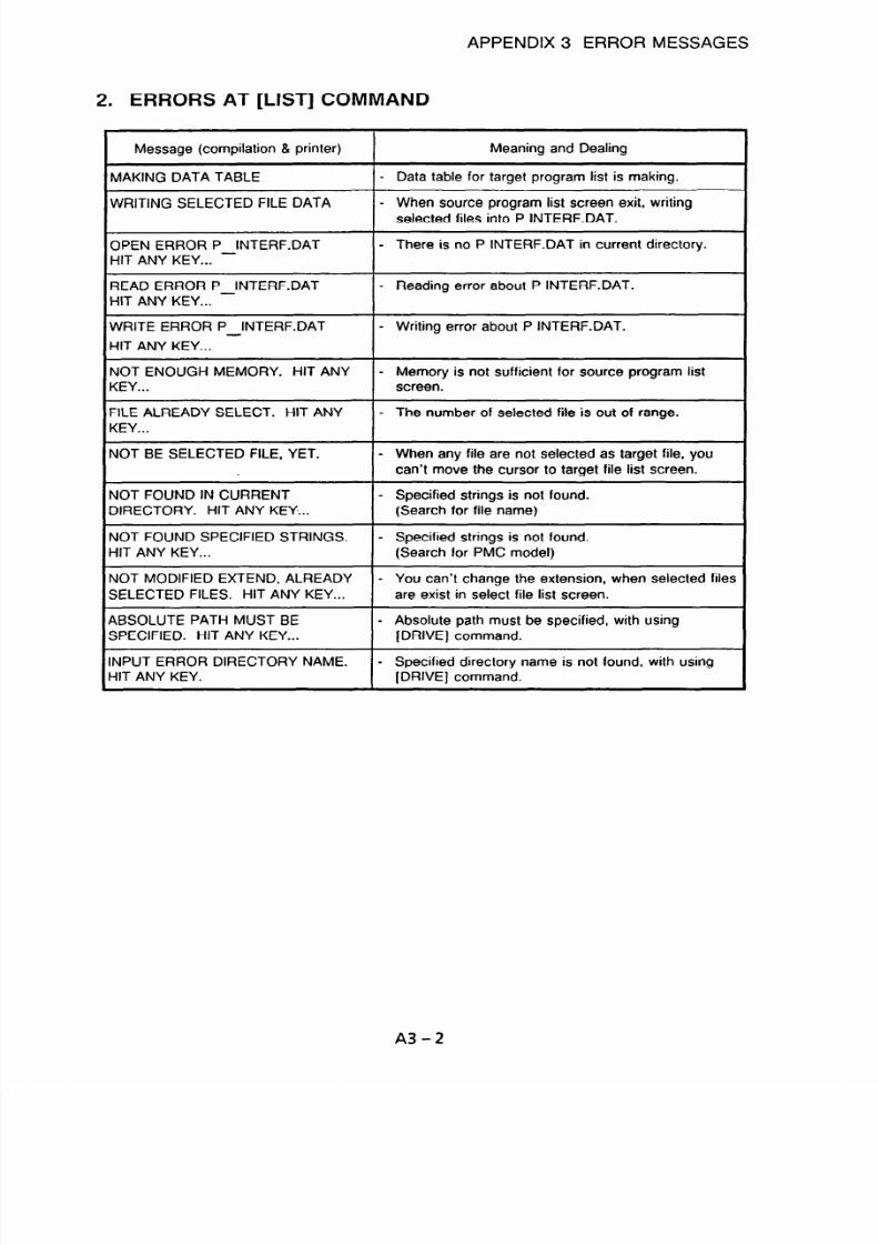
7/25/2019 FAPT Ladder for PC-Operator Manual
http://slidepdf.com/reader/full/fapt-ladder-for-pc-operator-manual 244/302
APPENDIX 3 ERROR MESSAGES
2. ERRORS AT [LIST] COMMAND
Message (compilation & printer)
MAKING DATA TABLE
WRITING SELECTED FILE DATA
Meaning and Dealing
- Data table for target program list is making.
- When source program list screen exit, writing
selected files into P INTERF.DAT.
OPEN ERROR P_INTERF.DAT
HIT ANY KEY...
- There is no P INTERF.DAT in current directory.
READ ERROR P_INTERF.DAT
HIT ANY KEY...
- Reading error about P INTERF.DAT.
WRITE ERROR P INTERF.DAT
HIT ANY KEY... -
- Writing error about P INTERF.DAT.
NOT ENOUGH MEMORY. HIT ANY
KEY...
FILE ALREADY SELECT. HIT ANY
KEY...
- Memory is not sufficient for source program list
screen.
- The number of selected file is out of range.
NOT BE SELECTED FILE, YET.
- When any file are not selected as target file, you
can’t move the cursor to target file list screen.
NOT FOUND IN CURRENT - Specified strings is not found.
DIRECTORY. HIT ANY KEY... (Search for file name)
NOT FOUND SPECIFIED STRINGS.
- Specified strings is not found.
HIT ANY KEY... (Search for PMC model)
NOT MODIFIED EXTEND, ALREADY - You can’t change the extension, when selected files
SELECTED FILES. HIT ANY KEY... are exist in select file list screen.
ABSOLUTE PATH MUST BE - Absolute path must be specified, with using
SPECIFIED. HIT ANY KEY... [DRIVE ] command.
INPUT ERROR DIRECTORY NAME. - Specified directory name is not found, with using
L-IIT ANY KEY. [DRIVE] command.
A3-2

7/25/2019 FAPT Ladder for PC-Operator Manual
http://slidepdf.com/reader/full/fapt-ladder-for-pc-operator-manual 245/302
APPENDIX 3 ERROR MESSAGES
3. EDITING (SOURCE PROGRAM SELECTION)
Message
Insufficient memory.
Description and action to be taken
- There is not sufficient main memory for loading an
executable file. An area of 500 KB or more is
required.
nsufficient disk space.
\lot found xxx Set-up file.
- Disk space was used up during file l/O.
- System setup file xxx does not exist in the system
directory.
\lot found xxx PMC-OS file.
- Software management file xxx does not exist in the
system directory.
(xx file I/O error.
- I/O error occurred for file xxx during creation of a
source program file.
llegal xxx Source-program name. - Invalid characters appear in the name, xxx, of the
input source program file.
inachine Kind And Input Program Not
>onsistency PMC series is xxx.
- Machine type for the input program and the
machine type for the system (common table file) do
not agree. Perform proper system setup for the
type of machine being used.
‘lease Appoint Program Name
- Neither the input program name nor the output
program name were specified when a source
program name was specified.
Output Program Already Exist
All Right? (Y/N)
- File already exists with the name specified for the
output program. To overwrite this file, enter ‘3”‘.
To cancel, enter “N”.
nake New Source Program
- Specified input/output program name does not
exist. A new file is being created.
‘lease Appoint Output Program Name - Specify an output program name.
Ippointed Input Program Not Exist
- Names of the input program and output program do
not agree and the input program does not exist.
xx Symbol & Comment data broken. - Symbol and comment data in input program xxx
contain error(s).
A3-3

7/25/2019 FAPT Ladder for PC-Operator Manual
http://slidepdf.com/reader/full/fapt-ladder-for-pc-operator-manual 246/302
APPENDIX 3 ERROR MESSAGES
3.1 Ladder Diagram Editing
Message
ILLEGAL OPERATION
Description and action to be taken
- Only the RETURN key was pressed.
- Address data input is incorrect.
EDIT BUFFER OVER
70LINE/l NET OVER
LARGE NET APPEARED
256STEP/l NET OVER
- Editing is not being performed within the limits
when creating function instructions.
- Function instructions cannot be created while the
cursor is on the right-hand side.
- Editing buffer was exceeded during net creation.
- Editing cannot be continued due to the large size of
nets being edited. Make nets smaller.
MNEMONIC BUFFER OVER - Attempt was made to make a LADDER program of
more than 21,840 (24,000 when an EMS board is
used) steps.
SET COUNT OVER
INPUT INVALID
- Too many items in data table
- Non-numeric character(s) were specified for
[COPY], [INSLIN], ]C-UP], or [C-DOWN].
- Input address was specified in a coil.
- Data table contains invalid character(s).
ADDRESS BIT NOTHING
RELAY OR COIL NOTHING
HORIZONTAL LINE ILLEGAL
- Relay or coil address is not specified.
- Relay or coil is required.
- Horizontal lines in LADDER diagram are
unconnected.
VERTICAL LINE ILLEGAL
‘ARAMETER NOTHING
-ADDER ILLEGAL
ERROR NET FOUND
- Vertical lines in LADDER diagram are incorrect.
- Function instruction parameters have not been set.
- LADDER diagram is incorrect.
- Incorrect net found when [COPY][MOVE] was
specified.
- Error found on the screen during a search beyond
the screen.
3ELAY OR COIL FORBIT
‘LEASE COMPLETE NET
LLEGAL NETS CLEARED
ADDRESS BIT NOTHING
- Unnecessary relay or coil exists.
- An incorrect net was found.
- Net which did not match the specified level of the
stack was found and deleted from the LADDER
program which was read in.
- Specified address was not found during address
search.
-UNCTION NOT FOUND
- Specified function instruction was not found during
function instruction search.
A3-4

7/25/2019 FAPT Ladder for PC-Operator Manual
http://slidepdf.com/reader/full/fapt-ladder-for-pc-operator-manual 247/302
APPENDIX 3 ERROR MESSAGES
Message
Description and action to be taken
STACK REGISTER OVER (8bit) ERR - There are 9 or more continuous stacks in the
LADDER program which was read in.
NOT EXIST APPOINT DATA SIZE - There is not enough data area for the specified file.
FILE NOT READ
- Disk space insufficient during writing
DISK SPACE NOTHING
- Error occurred when reading data from a file.
FILE NOT WRITE
- Error occurred when writing data to a file.
INSUFFICIENT MEMORY. HIT ANY - Area to be used in editing could not be acquired.
KEY
3.2
Other Editing (Applicable to Title, Message, System Parameter, Symbol
and Comment, and I/O Module Editing)
Message
File Read Error Hit Any Key
File Write Error Hit any Key
File I/O Error Hit Any Key
Not Enough Space
Same Symbol Data Exist
No Definition Address Appointed
Data Save Error
Not Found Data Error
Input Data Invalid
Appointed group Not Exist
Appointed Base Not Exist
Appointed Slot Not Exist
Appointed ID Code Not Exist
Input Key Not Used
Invalid Address Appoint
Description and action to be taken
- File could not be read.
- File could not be written.
- File I/O error occurred.
- Work area for message editing could not be
acquired due to insufficient memory.
- Symbol data already exists that is identical to
symbol data that was input.
- Nonexistent address was specified.
- Error occurred when symbol or comment data was
being registered in the work area.
- Required data could not be found during symbol
data lookup.
- There is an input error in the l/O module settings.
- There is an error in the group that was input.
- There is an error in the base that was input.
- There is an error in the slot that was input.
- There is an error in the ID code that was input.
- Undefined key was specified.
- Specified address could not be found during
search.
Invalid Value
Operate Panel Address Error
- Out-of-bound value was input.
- Data other than a numeric value was input.
- Addresses have not been set at the operation
panel.
A3-5

7/25/2019 FAPT Ladder for PC-Operator Manual
http://slidepdf.com/reader/full/fapt-ladder-for-pc-operator-manual 248/302
APPENDIX 3 ERROR MESSAGES
4. PRINTER
Message
DATA INPUT ERROR
Description and action to be taken
- There is an error in the data input in the setup
screens such as the type selection screen for
diagram output.
NOT FIND FILE
- Nonexistent file name was entered in the source
program selection screen.
DIFFERENT MACHINE CODE.
- Machine type codes in the common table file and
the management file do not agree.
WRITE ERROR COMONDAT.TBL.
HIT ANY KEY...
NOT EXIST AMROFTRP.DAT.
HIT ANY KEY...
WRITE ERROR AMROFTRP.DAT.
HIT ANY KEY...
DATA INVALID AMROFTRP.DAT.
HIT ANY KEY...
NOT ENOUGH MEMORY.
HIT ANY KEY...
FILE READ ERROR.
HIT ANY KEY...
- Error occurred when a program name was written
to the common table file.
- AMROFTRP.DAT (print format data file) does not
exist.
- Error occurred when the paper size was written to
AMROFTRP.DAT.
- Data in AMROFTRP.DAT is incorrect. Reinstall the
system program.
- Tried to acquire memory but there was no memory
area of a sufficient size.
- There is no title file or system parameter file.
- Either symbol or comment file could not be found
during LADDER diagram printing or cross-reference
printing.
- Existing file could not be read in.
CHANCEL PRINTER OUTPUT.
HIT ANY KEY...
- [BREAK] key was pressed during printing.
SEL SWITCH OFF
DATA INVALID ‘xxxxxxxX’.
HIT ANY KEY...
OPEN ERROR OUTPUT FILE.
HIT ANY KEY...
OUTPUT FILE NOT DEFINED.
HIT ANY KEY...
OUTPUT FILE ALREADY EXIST.
OVER WRITE (YIN)
WRITE ERROR OUTPUT FILE.
HIT ANY KEY...
CANCEL FILE OUTPUT.
HIT ANY KEY...
- SEL button of the printer is off. Turn it on.
- Error occurred during reading of the print format
data file.
- Error occurred during opening of output file. There
is not sufficient space on the disk.
- No output file is specified in the print format data
file.
- File exists with the same name as the output file.
Enter “Y” to overwrite or “N” to cancel output.
- Error occurred during writing to the output file.
There is not sufficient space on the disk.
- [BREAK] key was pressed during file output.
SYMBOL & COMMENT DATA
BROKEN. HIT ANY KEY...
- Symbol and comment data files are invalid.
A3-6

7/25/2019 FAPT Ladder for PC-Operator Manual
http://slidepdf.com/reader/full/fapt-ladder-for-pc-operator-manual 249/302
APPENDIX 3 ERROR MESSAGES
5. COMPILATION, DECOMPILATION, AND LINKING
Message Description and action to be taken
Error title 80
- Character code not permitted by PMC was found
during title compilation.
Illegal OP. PANEL (PARAMETER).
Proceed to discompile using ‘NO’
- System parameter that specifies use of the
operation panel was specified and there was an
invalid address specified in the external DI (KEY
data) address, external DO (LED) address, PMC
image address (DI), or PMC image address (DO).
This system parameter is forcibly turned off and
processing is continued (PMC-R series only).
Error message 60
- Size of a message exceeded the maximum size for
the system.
Error message 61
- Character code not permitted by PMC was found
during message compilation.
Error symbol/comment 70 - During compilation, the size of a symbol or
comment exceeded the maximum size for the
system.
Error symbol/comment 71
- During compilation, when the message area was
extended, symbol and comment data overflowed
the permitted ROM size.
Error symbol/comment 72 - Character code not permitted by PMC was found
during symbol compilation.
Error symbol/comment 73
- Character code not permitted by PMC was found
during comment compilation.
Error ladder 40
Error end 2
- During LADDER compilation, the size of the
LADDER program exceeded the maximum size for
the system.
Error ladder 41
- During LADDER compilation, when the symbol and
comment area was extended, the LADDER program
overflowed the permitted ROM size.
Error ladder 42
Error end 2
- Invalid intermediate LADDER code was found
during LADDER compilation.
- Invalid LADDER object was found during LADDER
decompilation.
Error ladder 48 - There is an invalid intermediate code in the
intermediate code file.
Error end 25 - There are no intermediate codes for the LADDER.
- There is no #LA file.
Error end 3
Error end 4
- Number of partition codes exceeded 99.
- Execution time for the first level ladder exceeds the
PMC default value or the time set in the system
parameter.
A3-7

7/25/2019 FAPT Ladder for PC-Operator Manual
http://slidepdf.com/reader/full/fapt-ladder-for-pc-operator-manual 250/302
APPENDIX 3 ERROR MESSAGES
Message
Description and action to be taken
Error end 17
- END2 was found before END1 or END1 was not
found before the LADDER program ended.
Error end 18
- END3 was found before END2 or END2 was not
found before the LADDER program ended.
Error end 19
- END3 was not found before the LADDER program
ended.
Error end 20
Error end 21
Error end 24
Error end 5
Error end 6
Error end 7
Error end 11
Error end 12
Error end 13
Error end 8
Error end 9
Error end 10
Error end 14
Error end 15
Error end 16
Error end 27
(Does not include third level ommission mode.)
- There is more than one ENDl.
- There is more than one END2.
- There is LADDER program code following END3
- END1 exists in common control mode.
- END2 exists in common control mode.
- END3 exists in common control mode.
- END1 exists in jump control mode.
- END2 exists in jump control mode.
- END3 exists in jump control mode.
- COM exists in common control mode.
- COME exists in common control mode in which the
number of coils is specified.
- COME exists outside of common control mode.
- JMP exists in jump control mode.
- JMPE exists in jump control mode in which the
number of coils is specified.
- JMPE exists outside of jump control mode.
- WRT or WRT.NOT does not exist following a
function instruction that requires WRT or
WRT.NOT.
Uarning end 29
- Number of coils was specified in a machine type for
which the number of JMP coils cannot be specified.
The parameter is forcibly set to 0 (JMPE
specification mode) and processing is continued.
Narning end 30
- Number of coils was specified in a machine type for
which the number of COM coils cannot be
specified. The parameter is forcibly set to 0 (JMPE
specification mode) and processing is continued.
A3-8

7/25/2019 FAPT Ladder for PC-Operator Manual
http://slidepdf.com/reader/full/fapt-ladder-for-pc-operator-manual 251/302
APPENDIX 3 ERROR MESSAGES
Message
Description and action to be taken
Error link 90 - During linking, SO record was not found before the
end of the load module.
- Different S record exists before the SO record.
Error link 92
- During linking, the value for the record length area
in the S2 record was less than 4.
- S record other than SO, S2, S8, or S9 was found.
- No S8 or S9 record was found before the end of
the load module.
irror link 93 - During linking, an attempt was made to load a load
module into an area other than the specified
address area.
\lot appoint source program name
- No source program was specified for compilation or
decompilation.
riot appoint ROM format file name - ROM format file name was not specified for
compilation, decompilation or linking.
Jot appoint load module file name
Iut of memory
- No load module file name was specified for linking.
- Work area required for processing cannot be
acquired. This occurs because a device driver
which requires a large amount of memory is
resident, because data is too large, or for some
similar reason.
Jot enough space
- Not enough space is available on disk for file
creation during compilation, decompilation or
linking.
:ile already exist
?enewal (Y/N)?
‘rogram already exist
?enewal (Y/N)?
qead error
- Name specified for ROM format file during
compilation already exists.
- #CN file of the source program specified for
decompilation already exists.
- #CN or #PA file of the source program specified for
compilation does not exist.
- Some sort of disk l/O error occurred.
Iead error
lead error
Vrite error
Vrite error
- ROM format file specified for decompilation or
linking does not exist.
- Machine type of the ROM format file specified for
decompilation differs from the machine type
specified in the machine type setting.
- Some sort of disk I/O error occurred.
- Load module file specified for linking does not exist.
- Some sort of disk l/O error occurred.
- Some sort of disk I/O error occurred.
- Some sort of disk I/O error occurred.
A3-9

7/25/2019 FAPT Ladder for PC-Operator Manual
http://slidepdf.com/reader/full/fapt-ladder-for-pc-operator-manual 252/302
APPENDIX 3 ERROR MESSAGES
Message
(System parameter) Read error
Description and action to be taken
- Some sort of disk I/O error occurred.
(Note) When no #PA file exists for the specified
source program, the following message is displayed.
“Cannot read source program j-l-j-\.”
(Title) Read error
(I/O module) Read error
(Message) Read error
Symbol) Read error
Comment) Read error
- Some sort of disk I/O error occurred.
(Note) Error termination does not occur even if no
#TA file exists for the specified source program.
- Some sort of disk I/O error occurred.
(Note) Error termination does not occur even if no
#IO file exists for the specified source program.
- Some sort of disk I/O error occurred.
(Note) Error termination does not occur even if no
#ME file exists for the specified source program.
- Some sort of disk I/O error occurred.
(Note) Error termination does not occur even if no
#SY file exists for the specified source program.
- Some sort of disk I/O error occurred.
(Note) Error termination does not occur even if no
#Cl file exists for the specified source program.
:Ladder) Read error
‘System parameter) Write error
:Title) Write error
‘I/O module) Write error
Message) Write error
Symbol) Write error
Comment) Write error
Ladder) Write error
EXECUTING
- Some sort of disk I/O error occurred.
(Note) Error termination does not occur even if no
#LA file exists for the specified source program.
- Some sort of disk I/O error occurred.
- Some sort of disk I/O error occurred.
- Some sort of disk I/O error occurred.
- Some sort of disk t/O error occurred.
- Some sort of disk I/O error occurred.
- Some sort of disk I/O error occurred.
- Some sort of disk I/O error occurred.
- Time-consuming processing is being performed
during compilation, decompilation, or linking.
(Note) This is not an error message.
A3-10

7/25/2019 FAPT Ladder for PC-Operator Manual
http://slidepdf.com/reader/full/fapt-ladder-for-pc-operator-manual 253/302
APPENDIX 3 ERROR MESSAGES
6.
COMPILE ERRORS
Compile errors can be divided into the following two basic groups:
- Error:Processing is stopped because of a fatal error. The processing can not be continued
unless the cause of the error has been removed.
- Warning: Processing of a subprogram for which a warning is output is stopped.
The processing of other subprograms is continued.
6.1 Path O/warning
001
- Editing sub-program has not completed ( Pn )
(Cause) The editing of a subprogram (Pn.$SJ) has not been completed.
002
- Multiple sub-program with same number exist ( Pn )
003 .
The title data which could not be display on the CNC was replaced with space code
(Cause) The title data contains a code which cannot be processed (a Japanese code,
for example).
004 *
Illegal OP.PANEL( PARAMETER ). Proceed to discompile using ‘NO’.
(Cause) Although the system parameter for the use of the FO machine operator’spanel
is set to YES, the DI/DO address data is not specified.
6.2 Path O/error/password
005 *
Verification error.
(Cause) The password is invalid.
(Cause) A ladder program and step sequence program have identical numbers.
006 * This word can not be used as password.Try another word.
(Cause) The entered password is not valid.
(Action) Enter another password.
007 * Only alphabetical and numerical characters are allowed.
(Cause) A non-alphanumeric character is specified.
6.3 Path O/error/others
008 - Not appoint source program.
(Cause) No source program name is specified.
009
* Not appoint ROM format file name.
(Cause) No ROM file name is specified.
A3-11
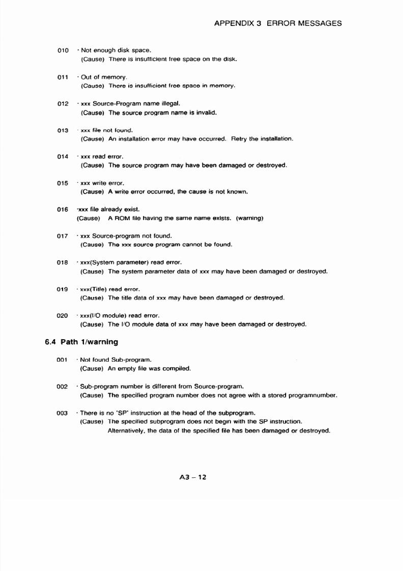
7/25/2019 FAPT Ladder for PC-Operator Manual
http://slidepdf.com/reader/full/fapt-ladder-for-pc-operator-manual 254/302
APPENDIX 3 ERROR MESSAGES
010
- Not enough disk space.
(Cause) There is insufficient free space on the disk.
011
- Out of memory.
(Cause) There is insufficient free space in memory.
012
* xxx Source-Program name illegal.
(Cause) The source program name is invalid.
013
- xxx file not found.
(Cause) An installation error may have occurred. Retry the installation.
014
* xxx read error.
(Cause) The source program may have been damaged or destroyed.
015
* xxx write error.
(Cause) A write error occurred, the cause is not known.
016
-xxx file already exist.
(Cause) A ROM file having the same name exists. (warning)
017
* xxx Source-program not found.
(Cause) The xxx source program cannot be found.
018
- xxx(System parameter) read error.
(Cause) The system parameter data of xxx may have been damaged or destroyed.
019
* xxx(Title) read error.
(Cause) The title data of xxx may have been damaged or destroyed.
020
* xxx(V0 module) read error.
(Cause) The I/O module data of xxx may have been damaged or destroyed.
6.4 Path l/warning
001
- Not found Sub-program.
(Cause) An empty file was compiled.
002
* Sub-program number is different from Source-program.
(Cause) The specified program number does not agree with a stored programnumber.
003
* There is no ‘SP’ instruction at the head of the subprogram.
(Cause) The specified subprogram does not begin with the SP instruction.
Alternatively, the data of the specified file has been damaged or destroyed.
A3-12

7/25/2019 FAPT Ladder for PC-Operator Manual
http://slidepdf.com/reader/full/fapt-ladder-for-pc-operator-manual 255/302
APPENDIX 3 ERROR MESSAGES
004
005
006
007
008
009
010
011
012
013
014
015
* ‘SP’ instruction was detected in the subprogram.
(Cause) Data was already present before SP instruction.
* There is no ‘SPE’ instruction at the bottom of the subprogram.
(Cause) Data remained after SPE instruction.
- There is an undefined instruction.
(Cause) A code of other than a step sequence instruction is stored.
* Specified value for a parameter of the xxxx instruction is outside the range.
(Cause) The parameter of the xxxx instruction falls outside the predetermined range.
* An illegal program number is specified for the xxxx instruction.
(Cause) The program number specified for the xxxx instruction falls outside the
predetermined range.
- An illegal label number is specifed for the xxxx instruction.
(Cause) The label number specified for the xxxx instruction falls outside the
predetermined range.
- The label of xxxx is used twice or more.
(Cause) A label number is duplicated within a single subprogram.
* The number of label exceeds the limit.
(Cause) An attempt was made to exceed the maximum number of labels that can be
defined in a single subprogram.
* Illegal ‘DSTEP’ instruction was detected,
(Cause) The DLBL instruction is not defined. Alternatively, the definition of the DSTEP
instruction is duplicated.
* LADDER execution time at the 1st level is too large.
(Cause) The overall execution time of the first level exceeds the predetermined limit.
(Action) Reduce the size of the program of the first level.
* The coil number specification of JMP instruction is not allowed.
.
(Cause) The parameter of the JMP instruction (number of coils to be jumped) is other
than 0.
(Action) Specify 0 for the parameter.
- The coil number specification of COM instruction is not allowed.
(Cause) The parameter of the COM instruction (number of coils to be controlled) is
other than 0.
(Action) Specify 0 for the parameter.
A3-13
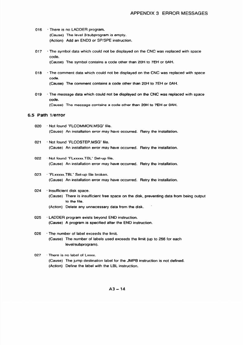
7/25/2019 FAPT Ladder for PC-Operator Manual
http://slidepdf.com/reader/full/fapt-ladder-for-pc-operator-manual 256/302
APPENDIX 3 ERROR MESSAGES
016
* There is no LADDER program.
(Cause) The level 3/subprogram is empty.
(Action) Add an END3 or SPSPE instruction.
017
- The symbol data which could not be displayed on the CNC was replaced with space
code.
(Cause) The symbol contains a code other than 20H to 7EH or OAH.
018
- The comment data which could not be displayed on the CNC was replaced with space
code.
(Cause) The comment contains a code other than 20H to 7EH or OAH.
019
* The message data which could not be displayed on the CNC was replaced with space
code.
(Cause) The message contains a code other than 20H to 7EH or OAH.
6.5 Path l/error
020
021
022
023
024
025
026
027
* Not found ‘FLCOMMON.MSG’ file.
(Cause) An installation error may have occurred. Retry the installation.
- Not found ‘FLCOSTEP.MSG’ file.
(Cause) An installation error may have occurred. Retry the installation.
- Not found ‘FLxxxxx.TBL’ Set-up file.
(Cause) An installation error may have occurred. Retry the installation.
* ‘FLxxxxx.TBL’ Set-up file broken.
(Cause) An installation error may have occurred. Retry the installation.
* Insufficient disk space.
(Cause) There is insufficient free space on the disk, preventing data from being output
to the file.
(Action) Delete any unnecessary data from the disk.
’
* LADDER program exists beyond END instruction.
(Cause) A program is specified after the END instruction.
* The number of label exceeds the limit.
(Cause) The number of labels used exceeds the limit (up to 256 for each
level/subprogram).
- There is no label of Lxxxx.
(Cause) The jump destination label for the JMPB instruction is not defined.
(Action) Define the label with the LBL instruction.
A3-14

7/25/2019 FAPT Ladder for PC-Operator Manual
http://slidepdf.com/reader/full/fapt-ladder-for-pc-operator-manual 257/302
APPENDIX 3 ERROR MESSAGES
028
029
030
031
032
033
034
035
036
037
038
039
040
041
042
- The label of Lxxxx is used twice or more.
(Cause) The definition of the label is duplicated.
* There is no END1 instruction.
(Cause) A program of level 1 does not end with an END1 instruction.
* There is no END2 instruction.
(Cause) A program of level 2 does not end with an END2 instruction.
- There is no END3 instruction.
(Cause) A program of level 3 does not end with an END3 instruction.
* There is no LADDER program.
(Cause) The program of level 1 or 2 is empty.
* There is no SP instruction at the head of the program.
(Cause) The first instruction of a subprogram is not SP.
. Illegal SPE instruction was detected.
(Cause) The SPE instruction is not preceded by the SP instruction.
- LADDER program exists beyond END1 instruction.
(Cause) Within level 1, a program is specified after the END1 instruction.
- LADDER program exists beyond END2 instruction.
(Cause) Within level 2, a program is specified after the END2 instruction.
* LADDER program exists beyond SPE instruction.
(Cause) In a subprogram, a program is specified after the SPE instruction.
* END1 instruction cannot be used excluding the 1st level.
(Cause) The use of the END1 instruction was attempted within level 2 or 3.
. END2 instruction cannot be used excluding the 2nd level.
(Cause) The use of the END2 instruction was attempted within level
1
or 3.
* END3 instruction cannot be used excluding the 3rd level.
(Cause) The use of the END3 instruction was attempted within level 1 or 2.
* END instruction cannot be used.
(Cause) The use of the END instruction was attempted within level 1.
* Program number is different from program name.
(Cause) The subprogram file number does not agree with the number specified in the
parameter of the SP instruction.
A3-15

7/25/2019 FAPT Ladder for PC-Operator Manual
http://slidepdf.com/reader/full/fapt-ladder-for-pc-operator-manual 258/302
APPENDIX 3 ERROR MESSAGES
43
44
45
46
47
48
49
5
051
52
53
54
55
- The size of LADDER program is too large.
(Cause) The object size of the ladder program exceeds the predetermined limit.
(Action) Reduce the size of the ladder program.
* The range controled by COM instruction is beyond END1 instruction.
(Cause) An END1 instruction was encountered before the COME instruction.
* The range controled by COM instruction is beyond END2 instruction.
(Cause) An END2 instruction was encountered before the COME instruction.
* The range controled by COM instruction is beyond END3 instruction.
(Cause) An END3 instruction was encountered before the COME instruction.
- COM instruction was detected in the COM mode.
(Cause) A COM instruction was encountered before the COME instruction.
(Action) Terminate control with the COME instruction, then restart control with the
COM instruction.
- Illegal COME instruction was detected.
(Cause) The COM instruction cannot be found before the COME instruction.
* The destination of JMP instruction is beyond END1 instruction.
(Cause) An END1 instruction was encountered before the JMPE instruction.
. The destination of JMP instruction is beyond END2 instruction.
(Cause) An END2 instruction was encountered before the JMPE instruction.
- The destination of JMP instruction is beyond END3 instruction.
(Cause) An END3 instruction was encountered before the JMPE instruction.
* JMP instruction was detected in the JMP mode.
(Cause) A JMP instruction was encountered before the JMPE instruction.
(Action) Terminate control with the JMPE instruction, then restart control with the JMP
instruction.
* Illegal JMPE instruction was detected.
(Cause) The JMP instruction cannot be found before the JMPE instruction.
- LADDER program exists beyond END3 instruction.
(Cause) Within level 3, a program is specified after the END3 instruction.
* LADDER program is broken.
(Cause) No instructions can be recoonized.
A3-16

7/25/2019 FAPT Ladder for PC-Operator Manual
http://slidepdf.com/reader/full/fapt-ladder-for-pc-operator-manual 259/302
APPENDIX 3 ERROR MESSAGES
056
057
058
059
060
061
062
063
064
065
066
067
068
069
* There is no coil in the functional instruction which needs the coil.
(Cause) No output instruction is specified after a functional instruction which requires
output.
* SP instruction can not be used in the main program.
(Cause) The use of the SP instruction was attempted within the main program.
. SPE instruction can not be used in the main program.
(Cause) The use of the SPE instruction was attempted within the main program.
* END1 instruction can not be used in the subprogram.
(Cause) The use of the END1 instruction was attempted within a subprogram.
* END2 instruction can not be used in the subprogram.
(Cause) The use of the END2 instruction was attempted within a subprogram.
- END3 instruction can not be used in the subprogram.
(Cause) The use of the END3 instruction was attempted within a subprogram.
* Specified value for a parameter of the functional instruction is outside the range.
(Cause) An illegal value has been specified for the parameter of a functional
instruction.
* An illegal program number is specified for the CALL instruction.
(Cause) A non-P address has been specified for the parameter of the CALL
instruction.
’ An illegal program number is specified for the CALLU instruction.
(Cause) A non-P address has been specified for the parameter of the CALLU
instruction.
. An illegal program number is specified for the SP instruction.
(Cause) A non-P address has been specified for the parameter of the SP instruction.
. There is an undefined instruction.
(Cause) An attempt was made to use a basic or functional instruction which is not
supported by the selected model.
* There is no SPE instruction at the bottom of the subprogram.
(Cause) A subprogram does not end with the SPE instruction.
* SP instruction was detected in the subprogram.
(Cause) An SP instruction was encountered before an SPE instruction.
* The range controled by COM instruction is beyond SPE instruction.
(Cause) An SPE instruction was encountered before a COME instruction.
A3-17

7/25/2019 FAPT Ladder for PC-Operator Manual
http://slidepdf.com/reader/full/fapt-ladder-for-pc-operator-manual 260/302
APPENDIX 3 ERROR MESSAGES
070
071
072
073
074
075
076
077
078
079
080
081
082
083
* The destination of JMP instruction is beyond SPE instruction.
(Cause) An SPE instruction was encountered before a JMPE instruction.
* CALL instruction cannot be used excluding the 2nd level.
(Cause) The use of the CALL instruction was attempted within level 1 or 3.
* CALLU instruction cannot be used excluding the 2nd level.
(Cause) The use of the CALLU instruction was attempted within level 1 or 3.
. The range controled by COM instruction is beyond END instruction.
(Cause) An END instruction was encountered before a COME instruction.
- The destination of JMP instruction is beyond END instruction.
(Cause) An END instruction was encountered before a JMPE instruction.
* The range controled by COM instruction is beyond SP instruction.
(Cause) An SP instruction was encountered before a COME instruction.
* The destination of JMP instruction is beyond SP instruction.
(Cause) An SP instruction was encountered before a JMPE instruction.
- The range controled by COM instruction is beyond CALL instruction.
(Cause) A CALL instruction was encountered before a COME instruction.
. The range controled by COM instruction is beyond CALLU instruction.
(Cause) A CALLU instruction was encountered before a COME instruction.
- The destination of JMPB instruction is beyond COM instruction.
(Cause) An attempt was made to execute the JMPB instruction from the outside to the
inside, or from the inside to the outside, of common line control.
* JMPC instruction cannot be used in the main program.
(Cause) The use of the JMPC instruction was attempted within the main program.
. An illegal label number is specified for the JMPB instruction.
(Cause) A non-L address has been specified as the parameter of the JMPB
instruction.
* An illegal label number is specified for the LBL instruction.
(Cause) A non-L address has been specified as the parameter of the LBL instruction.
- An illegal label number is specified for the JMPC instruction.
(Cause) A non-L address has been specified as the parameter of the JMPC
instruction.
A3-18

7/25/2019 FAPT Ladder for PC-Operator Manual
http://slidepdf.com/reader/full/fapt-ladder-for-pc-operator-manual 261/302
APPENDIX 3 ERROR MESSAGES
6.6Path 2/warning
001 * Unreferenced subprogram Pxxxx.
(Cause) A subprogram which is not called by a CALL or CALLU instruction is
encountered.
6.7 Path 2/error
002
003
004
005
006
007
008
009
010
011
* Data too large. ( message + symbol + comment )
(Cause) The total size of the message, symbol, and comment data exceeds the
predetermined limit.
* Data too large. ( ladder + step sequence )
(Cause) The total size of the ladder and step sequence data exceeds the
predetermined limit.
- Data too large. ( message + symbol + comment + ladder + step sequence )
(Cause) The total size of the message, symbol, comment, ladder, and step sequence
data exceeds the predetermined limit.
* The number of label exceeds the limit. ( xxxx net in LEVELx.#LA )
(Cause) The total number of labels used within LEVELl, LEVEL2, or LEVEL3 exceeds
the predetermined limit.
* The label of Lxxxx is used twice or more. ( xxxx net in LEVELx.#LA )
(Cause) An identical L address is specified for two or more labels in LEVELl, LEVEL2,
or LEVELB.
* Program exists beyond END inctruction. ( Pxxx.#LA )
(Cause) A program including an END instruction is followed by another program.
- There is no label of Lxxxx. ( xxxx net in LEVELx.#LA )
(Cause) The destination label of JMPC cannot be found in LEVEL2.#LA.
* The label of Lxxxx exists in the COM mode. ( xxxx net in Pxxxx.#LA )
(Cause) The destination label of JMPC is found between COM and COME.
- The label of Lxxxx to refer exists in another level. ( xxxx net in Pxxxx.#LA )
(Cause) The destination label of JMPC is found in LEVELl.#LA or LEVEL3.#LA.
- There is no subprogram Pxxxx. ( xxxx net in LEVELx.#LA )
(Cause) The subprogram to be called by CALL or CALLU cannot be found or is empty.
A3-19

7/25/2019 FAPT Ladder for PC-Operator Manual
http://slidepdf.com/reader/full/fapt-ladder-for-pc-operator-manual 262/302
APPENDIX 3 ERROR MESSAGES
7. INPUT AND OUTPUT
Message
INVALID RECEIVE DATA
TIME OUT ERROR
Description and action to be taken
- Data other than IS0 codes was sent.
- During reception processing, a command was sent
from the PC, but there was no response within a
certain period of time. Confirm for the receiving
side that the power is on, settings are correct,
cables are properly connected, parameters (baud
rate and stop bits) are correct, and that
CONFIG.SYS is correct.
‘xxxx.DAT’ file format error.
4it any key
VOT EXIST APPOINT ROM FORM
=lLE
- No xxx.DAT files exist in the directory containing
FAPT LADDER. Install the system again.
- Specified ROM format file does not exist on the
disk [write and verification for the ROM writer,
download and comparison for the PMC].
ALREADY EXIST FILE
- Specified file already exists [read operation for the
3JPERSCRlPTlON REAL FILE? (Y/N)
ROM writer, upload or the PMC]. To overwrite,
enter “Y”. To change the name of the file, enter
“N”.
3OW PARITY ERROR OF APPOINT
-ILE
- There is an error in the ROM parity of the specified
ROM format file [write operation for the ROM
writer].
3OM PARITY WARNING OF
4PPOINT FILE. CONTINUE TO
TRANSFER? (Y/N)
- There is an error in the ROM parity of the specified
ROM format file [download for the PMC]. To
download in this state, enter “Y”. To cancel, enter
“N”.
3OM PARITY WARNING OF
APPOINT FILE
- There is an error in the ROM parity of the specified
ROM format file [read operation for the ROM writer,
upload for the PMC).
NAITING FOR RECEIVE. WHEN TO
- No data was received during transmission [read
STOP. PUSH BREAK KEY
operation for the ROM writer, upload for the PMC].
Press the break key to interrupt processing, then
check cable connections and the power supply, etc.
of the sending side.
NITIALIZE EXECUTE - Work file is being created during upload from PMC
(PMC-N).
- Checking ROM data parity [write operation for the
ROM writer, download for the PMCJ. Wait while
processing is performed.
4OM ID UNMATCH ERROR
- Inserted cassette or module is incorrect for the
present machine type (PMC-N, 431.
:ILE OPEN ERROR
- Cannot open specified ROM format file.
:ILE CLOSE ERROR
- Cannot close specified ROM format file.
‘ILE WRITE ERROR - Cannot write to specified ROM format file.
A3-20

7/25/2019 FAPT Ladder for PC-Operator Manual
http://slidepdf.com/reader/full/fapt-ladder-for-pc-operator-manual 263/302
APPENDIX 3 ERROR MESSAGES
Message
Description and action to be taken
I
ILE READ ERROR
I
- Cannot read from specified ROM format file.
ROM FILE > ROM ERROR
I-
- During writing, the specified ROM format file could
not be fully written to ROM (cassette or module).
I
OM FILE FORMAT ERROR
I
ROM file format is incorrect.
WORK FILE INITIALIZE ERROR - There is not enough space on the disk for the work
file area (512K bytes) [PMC-N].
ROM SET ERROR
EROM OUT LEVEL ERROR
IWIIT.5
- EROM is installed with incorrect orientation.
- EROM is faulty.
- Cannot write to EROM because it has not yet been
erased.
- EROM has not yet been erased.
DATA SEND ERROR - The number of the sent data items does not match
that of the received data items.
PARITY ERROR
- A parity error occurred during data transfer.
RUNNING WRITER ERROR - The ROM writer is being used.
ROW TYPE ERROR
PORT ERROR (OVER RUN)
PORT ERROR (PARITY)
- Incorrect type of ROM
- Overrun (determined by the status check
information from I/O ports)
- Parity error (determined by the status check
information from I/O ports)
I
ORT ERROR (FRAMING)
- Framing error (determined by the status check
information from I/O ports)
I
ORT ERROR (BREAK INTERRUPT)
- Break interrupt error (determined by the status
check information from I/O ports)
- Time-out error (determined by the status check
information from I/O ports)
- Data transfer error (determined by the status check
information from l/O ports)
~
IMER SET/CANCEL ERROR
- The system timer malfunctions. Update the text file
(FL10 AT.DAT) information. For details, see the
comments of the file.
A3-21

7/25/2019 FAPT Ladder for PC-Operator Manual
http://slidepdf.com/reader/full/fapt-ladder-for-pc-operator-manual 264/302
APPENDIX 3 ERROR MESSAGES
8. MNEMONIC EDITING
8.1 Mnemonic Editing (System Parameters >
Message
Invalid qualifier.
Description and action to be taken
- System parameter is followed by invalid
character(s).
Unknown data number.
- Data number was specified that does not exist in
the system parameters.
Illegal value.
Out of value.
- System parameter contains invalid numerical data.
- System parameter contains out-of-bound numerical
data.
Expected a multiple of 5.
Expected a multiple of 2.
- System parameter required to be a multiple of 5 is
not a multiple of 5.
- System parameter required to be a multiple of 2 is
not a multiple of 2.
Illegal character(s).
Data not found.
Too many characters in 1 line.
- System parameter contains invalid character(s).
- There is no system parameter data.
- System parameter contains a line of data that
exceeds the maximum allowed number of
characters.
Illegal data number.
Too long strings.
Illegal address
Expected parameter(s)
Illegal OP. PANEL (PARAMETER)
Proceed to discompile using ‘NO’.
- System parameter contains invalid data number(s).
- System parameter contains character data that
exceeds the maximum length.
- System parameter contains an invalid address.
- System parameter is missing or incomplete.
- As OP.PANEL (parameter) of the system
parameters is invalid, it is assumed to be “NO”
and operation continues.
A3-22

7/25/2019 FAPT Ladder for PC-Operator Manual
http://slidepdf.com/reader/full/fapt-ladder-for-pc-operator-manual 265/302
APPENDIX 3 ERROR MESSAGES
8.2 Mnemonic Editing <Title Data B
Message
Invalid qualifier.
Unknown data number.
Too long strings.
Include KANA or KANJI character(s).
Illegal character(s)
Data not found.
Too many characters in 1 line.
Description and action to be taken
- Title data is followed by invalid character(s).
- Specified data identifier number does not exist.
- Length of title data exceeded the maximum length.
- Title data contains m-type characters.
- Title data contains invalid character data.
- There is no title data.
- Title data contains a line of data that exceeds the
maximum allowed number of characters.
Illegal title number. - Data identifier number specified is incorrect.
8.3 Mnemonic Editing (Symbol and Comment Data >
Message
SYMBOL data not found.
Invalid qualifier.
Illegal character(s).
Description and action to be taken
- Comment data exists, but there is no symbol data.
- Symbol and comment data is followed by invalid
character(s).
- Invalid character data was specified in symbol and
comment data.
Illegal address. - Invalid address was specified in symbol and
comment data.
Redefinition of address data.
- Symbol and comment data contain identical
address data.
Redefinition of symbol data. - Mnemonic symbol data contains identical symbol
data.
Include KANA or KANJI character(s) in
- Comment data which contains m-type characters
comment data. was converted without the m-type character
conversion option (J option).
Data not found.
Too long characters in 1 line.
- There is no symbol or comment data.
- Symbol or comment data contains a line of data
that exceeds the maximum allowed number of
characters.
Comment data not found.
Symbol or comment data not found.
- Only symbol data was converted for the address.
- Only symbol or comment data was converted for
the address.
Out of address limits.
- Mnemonic data contains an address that is out of
bounds.
A3-23

7/25/2019 FAPT Ladder for PC-Operator Manual
http://slidepdf.com/reader/full/fapt-ladder-for-pc-operator-manual 266/302
APPENDIX 3 ERROR MESSAGES
8.4 Mnemonic Editing (LADDER Data >
Message
Description and action to be taken
Expected address.
- Basic command has no address.
invalid qualifier. - LADDER data is followed by invalid character(s).
Expected parameter(s). - Function instruction has no parameters.
Not enough parameter(s). - Function instruction is missing parameters.
Too many parameters.
- Function instruction has too many parameters.
Illegal address.
- Unspecifiable address was specified.
Out of address limits.
- Out-of-bound address was specified.
Undefined instruction.
- Data contains an undefined command.
Invalid function’s name. - Unspecifiable function instruction was specified.
Cannot specify byte address on basic
- Byte address was specified in a basic command.
instruction.
Cannot specify the input address with - Address which cannot be output was specified in a
coil. coil.
Cannot specify the odd address. - Odd address was specified for an address that
cannot be odd.
Illegal value of parameter.
- Numeric parameter of a function instruction
contains an incorrect value.
Dut of parameter value. - Numeric parameter of a function instruction
contains a value that exceeds the maximum.
Cannot specify bit address of
oarameter.
Cannot specify the input address.
- Bit address was specified in the byte address
parameter of a function instruction.
- Address which cannot be output was specified for
the output address parameter of a function
instruction.
Cannot specify the address prohibited
- Address which cannot be specified as a parameter
Jsing as parameter.
was specified as a function instruction address
parameter.
llegal address of parameter. - Invalid address was specified in a function
instruction address parameter.
llegal value of parameter.
- Invalid value was specified in the function
instruction data table.
3ut of value in data table.
- Out-of-bound value was specified in the function
instruction data table.
_ogical product remains in register(s).
- LADDER data contains a register which is not
output.
_ogical operated with unused
- Operation was performed with a register which was
,egister(s).
not input in LADDER data.
A3-24

7/25/2019 FAPT Ladder for PC-Operator Manual
http://slidepdf.com/reader/full/fapt-ladder-for-pc-operator-manual 267/302
APPENDIX 3 ERROR MESSAGES
Message
Not enough control condition(s).
Description and action to be taken
- Function instruction control conditions are
insufficient.
Too many control conditions.
Expected control condition(s).
Data not found.
Unexpected address.
Unexpected parameter(s).
Unexpected control condition(s).
Unexpected coil(s).
Too many characters in 1 line.
- Too many function instruction control conditions.
- There are no function instruction control conditions.
- There is no LADDER data.
- Address was specified in a section that does not
require an address.
- Parameter was specified for a function instruction
that does not require parameters.
- Basic command was specified for a function
instruction that does not require control conditions.
- Coil was specified for a function instruction that
does not require coils.
- Mnemonic data contains a line of characters that
exceeds that maximum allowed number of
characters.
3ut of address limits of parameter.
- Function instruction parameter contains an out-of-
bound address.
llegal address in data table.
- Function instruction data table contains an invalid
address.
3ut of address limits in data table.
- Function instruction data table contains an out-of-
bound address.
A3-25

7/25/2019 FAPT Ladder for PC-Operator Manual
http://slidepdf.com/reader/full/fapt-ladder-for-pc-operator-manual 268/302
APPENDIX 3
ERROR MESSAGES
8.5
Mnemonic Editing <Message Data>
Message
Too long strings.
Illegal address.
Include KANA or KANJI character(s).
Invalid qualifier.
Data not found.
Too many characters in 1 line.
Description and action to be taken
- Length of message data exceeds the maximum
allowed length.
- Invalid address was specified for the message
setting address.
- Message data contains m-type characters.
- Message data is followed by invalid character(s).
- There is no message data.
- Message data contains a line of characters that
exceeds the maximum allowed number of
characters.
Out of address limits of address. - Message setting address contains an out-of-bound
address.
Illegal character(s).
Not found data at $ address.
- Message data contains invalid character data.
- Mnemonic message data was not specified. Only
mnemonic address data was specified.
Cannot convert in case of specified - Specified machine type and data machine type do
PMC series.
not agree.
A3-26

7/25/2019 FAPT Ladder for PC-Operator Manual
http://slidepdf.com/reader/full/fapt-ladder-for-pc-operator-manual 269/302
APPENDIX 3 ERROR MESSAGES
8.6 Mnemonic Editing <I/O Module Data>
Message
Invalid qualifier.
Illegal address.
Description and action to be taken
- I/O module data is followed by invalid character(s).
- Invalid address specified for l/O module data
address.
Out of address limits. - Out-of-bound address specified for I/O module data
address.
Not found group data.
Illegal value in group data.
- l/O module data has no group data.
- Group data of I/O module data contains an invalid
value.
Out of value in group data.
- Group data of I/O module data contains an out-of-
bound value.
Not found base data.
811egal alue in base data.
- l/O module data has no base data.
- Base data of I/O module data contains an invalid
value.
Dut of value in base data. - Base data of l/O module data contains an out-of-
bound value.
Vat found slot data.
llegal value in slot data.
- I/O module data has no slot data.
- Slot data of l/O module data contains an invalid
value.
3ut of value in slot data. - Slot data of I/O module data contains an out-of-
bound value.
\lot found module name.
- I/O module data has no module name.
nvalid module name.
- I/O module data has an invalid module name.
Cannot specify output module at input
- Output module is specified at the input address of
Iddress.
the l/O module data.
Cannot specify input module at output
- Input module is specified at the output address of
address.
the I/O module data.
2annot specify same group, base and
- Group, base, and slot data of I/O module data have
;lot.
the same data.
rot.9 value of base and slot is over.
- Sum of base and slot data of I/O module data
exceeds the maximum allowed value.
Data not found.
Too many characters in 1 line.
- There is no I/O module data.
- I/O module data contains a line of characters that
exceeds the maximum allowed number of
characters.
2annot convert in case of specified
- Specified machine type and conversion data
‘MC series.
machine type do not agree.
A3-27

7/25/2019 FAPT Ladder for PC-Operator Manual
http://slidepdf.com/reader/full/fapt-ladder-for-pc-operator-manual 270/302
APPENDIX 3 ERROR MESSAGES
9. STEP SEQUENCE EDITING ERRORS
Error message
Illegal source code
Symbol file read error
Comment file read error
Title file read error
Memory allocation error
Insufficient disk space
Buffer size over
Number of nest branch too big
Number of branch too big
Size of table buffer too big
Unconnected step sequence diagram
Selected branch error
Parallel branch error
Syntax error
Step line syntax error
Transition line syntax error
Cannot insert
Cannot make diagram
Horizontal fine illegal
Description
The input file data is illegal.
The symbol data cannot be read.
The comment data cannot be read.
The title data cannot be read.
Sufficient memory space cannot be allocated.
There is insufficient free space on the specified drive.
The program is too large.
The program contains too many branches.
The program contains too many branches.
The program is too large.
A line is not connected.
The program contains too many branches.
The program contains too many branches.
A syntax error is found.
A step line contains an illegal code.
A transition line contains an illegal code.
The program is too large.
The wrong soft key was pressed to change an
element.
The point at which a branch must be closed is left as
a horizontal line.
Jump forward check error
The jump destination cannot be found.
File open error
The specified file cannot be found.
File close error The file cannot be closed.
Check incomplete error
The source program contains an illegal code.
Chart sequence error
The sequence is incorrect.
Chart start code error
The beginning of the sequence is incorrect.
Chart end code error
The end of the sequence is incorrect.
Jump close error
An instruction is encountered after a label jump.
-horizontal line duplicate error
The sequence is incorrect.
3ranch unconnected error
A branch is not closed.
3ranch sequence error A branch is invalid.
A3-28

7/25/2019 FAPT Ladder for PC-Operator Manual
http://slidepdf.com/reader/full/fapt-ladder-for-pc-operator-manual 271/302
APPENDIX 3 ERROR MESSAGES
Error message
Description
Cannot copy diagrams
The program is too large.
Cannot move diagrams
Illegal specified position
The program is too large.
The corresponding coordinates cannot be found.
Strings not Found
Step Number Duplicate Error
The specified character string cannot be found.
The specified step number is being used by another
subprogram.
Label Number Duplicate Error
Cannot delete temporary file
Same sub-program name exists
The specified label is used in two or more positions.
The temporary file cannot be deleted.
A file having the same name, but a different extension,
exists.
I
nput invarid
The specified address data exceeds the
predetermined range.
Expected address
Sub-program of nest branch too big
No subprogram number is specified.
An attempt was made to nest a program to a level of
eight or more, by using the [ZOOM] key.
A3-29

7/25/2019 FAPT Ladder for PC-Operator Manual
http://slidepdf.com/reader/full/fapt-ladder-for-pc-operator-manual 272/302
APPENDIX 4
APPENDIX 4 MODULAR PROGRAMMING
(PMC=RA3/RB3/RC3 ONLY)
MODULAR PROGRAMMING
(PMC-RA3/RB3/RC3 ONLY)
The PMCRA3/RB3’RC3 has special sub-program functions that allow modular programming.
When the sub-program function is used, a Ladder program, which must have been coded as an
unbroken sequence before, can be coded in units of sub-programs.
The sub-program function enables FAPT LADDER to manage a program by dividing it into two or
more modules (modular programming.)
The modular programming is accomplished by the
module from a program and connect a module to a
modules.
ladder diagram editing function to produce a
program and the compile function to connect
In the later part of this book, the terms “module” and “source program” mean the following:
0 Module
: Logical unit of a program. A module does not always correspond to a sub-
program. A single module can be the first or
or a group of sub-programs.
Source program
: Physical unit of a program stored on a floppy
second half of the main program
disk or hard disk
1. LADDER DIAGRAM EDITING FUNCTION
(1) Dividing a source program
The function copies or moves a part of a source program and creates another program, to
which a name is specified.
0 The function produces a module from a program.
Source program
Module
A4-1

7/25/2019 FAPT Ladder for PC-Operator Manual
http://slidepdf.com/reader/full/fapt-ladder-for-pc-operator-manual 273/302
APPENDIX 4 MODULAR PROGRAMMING
(PMC-RA3/RB3/RC3 ONLY)
(2) Combining source programs
The function combines all or part of a source program to another source program that is
being edited.
The function combines a module (program) to another program.
Source program
Module
For the details of (1) and (2), see (8) “Copying
5.1.2, “Ladder Diagram Editing.”
Source program
*..*
_....
.
*
Edit .
<.....
..’
. ..*.
.
Sections of a Sequence
Source program
Program” in Section
2. COMPILE FUNCTION
(1) Combining modules
The function compiles a batch of separately edited programs and unites the programs.
0 The files to be combined can be specified in a control statement (text file having the
extension #LS).
0 The control statement is coded by the [LIST] command on the compile or print screen.
0 The function can handle modules (files) made up of any units (nets or sub-programs).
Control statement
(MAINFILE.#LS)
MAINFILE.#LA 1 Main program 1
I
I
1 I
SUBFILEl.#LA 1 Sub-program 1 1
,
SUBFILE2.#LA I Sub-program 2 I
I
I
File selection
MAINFILE
SUBFILEI
SUBFILE
.
SUBFlLEn
.
.
SUBFILEn.#LA
ROM data
Main program
I
Sub-program 1 1
Sub-program 2 1
.
.
Sub-program n 1
For details, see Section 5.3, “Compilation.”
A4-2

7/25/2019 FAPT Ladder for PC-Operator Manual
http://slidepdf.com/reader/full/fapt-ladder-for-pc-operator-manual 274/302
(2)
Control statement (.#LS file)
The .#LS file is a MS-DOS text file in which the source programs to be combined are coded in
the order in which they are combined. See the following example.
Sample control statement (File name = MAIN.#LS)
~
Parameters, symbols, comments, the title, and other data, except data for the ladder, from the
first program are used for the second and later programs.
(3)
Advantages
APPENDIX 4 MODULAR PROGRAMMING
(PMC-RA3/RB3/RC3 ONLY)
0 Programs can be edited quickly and easily because small source programs are handled.
0 A source program in the control statement can be used for another purpose only by
changing its name.
Program
1
Program 2
ESub-program
A4-3

7/25/2019 FAPT Ladder for PC-Operator Manual
http://slidepdf.com/reader/full/fapt-ladder-for-pc-operator-manual 275/302
APPENDIX 5 BOOT SYSTEM OPERATING PROCEDURE (FOR THE FSZO)
APPENDIX 5 BOOT SYSTEM OPERATING PROCEDURE
(FOR THE FS20)
This appendix describes how to use the BOOT SYSTEM for the FS20. The operating procedure
varies from one CNC model to another. For other models such as the FSlSB (PMC-NA), refer to
the respective manuals.
AS-1

7/25/2019 FAPT Ladder for PC-Operator Manual
http://slidepdf.com/reader/full/fapt-ladder-for-pc-operator-manual 276/302
APPENDIX 5 BOOT SYSTEM OPERATING PROCEDURE (FOR THE FSZO)
r (NEXT]
Hold down the [NEXT] key and a soft key
at its immediate left simultaneously, and
switch on the NC. The IPL screen will
appear (00).
The entry procedure is described below
(0 to 0).
@ Hold dowrf both simultaneously.
@ Switch on the power.
SYSTEM MONITOR MAIN MENU
'liB:i';~~f~~~~~~~~~~~~~~~~,
2. SYSTEM'DATA CHECK
3. SYSTEM DATA DELETE
*** MESSAGE **
SELECT
MODE
AND HIT [SELECT]
KEY
[SELECT] [ YES I[ ~0 11 up
1 [
DOWN ]
@ Place the cursor on ” 1. SYSTEM
DATA LOADING” using [UP] or
[DOWN], then press [SELECT].
B
'SYSTEM DATA LOADING
Place the cursor on the
FILE DIRECTORY
~~~~~~~~
desired filename using TEST. DAT “’
[UP] or [DOWN], then END
press [SELECT].
***
MESSAGE **
SELECT FILE AND HIT [SELECT] KEY
=-I
SELECT] [ YES 1 [ ~0 1 [ up 1 [ DOWN 1
0 Press [YES] or [NO].
I
I
t
I
-
Cy
1
** MESSAGE ***
LOADING OK ? HIT [YES] OR [NO] KEY.
(SELECT][ YES ][ NO ][ UP ][ DOWN ]
I
I
/
I
I
*** MESSAGE ***
HIT [SELECT] KEY.
ILLEGAL FORMAT FILE
[SELECT]
I
YES I[ NO ]I UP
I[
DOWN
]
A file in a format that cannot be
was selected.
End of entry
:\ j
I
handled by the BOOT SYSTEM -
LOADING COMPLETE. HIT [SELECT] KEY.
[SELECT] [ YES I[ NO I[ up
I[
DOWN
1
AS-2

7/25/2019 FAPT Ladder for PC-Operator Manual
http://slidepdf.com/reader/full/fapt-ladder-for-pc-operator-manual 277/302
APPENDIX 6
APPENDIX 6 MEMORY CARD COMPATIBILITY
(FOR THE PMC-RAl/RA3, NB, AND QC)
MEMORY CARD COMPATIBILITY
(FOR THE PMGRAlIRA3, NB, AND QC)
If a CNC or off-line programmer operating on an upgraded edition is used to output a sequence
program to a memory card, the sequence program may not be able to be input to a
CNC
or off-line
programmer operating on an earlier edition (see below).
Series 4080, edition 06
Series 4080, edition 04
Series 4047, edition 01
Series 4054, edition 01
CNC
Off-line programmer
A08B-XXXX-J502, editions 06.3 and later
A08B-XXXX-J501, editions 06.2 and later
AO8B-XXXX-J502, editions 06.1 and later
: Operating on an upgraded edition
f- -+ : Unconditionally possible
+___ ___+
: Possible under some condition
: Operating on an earlier edition
Cases 0, 0, 0, and 0, where input/output is possible under some condition, are explained
below.
A6-1

7/25/2019 FAPT Ladder for PC-Operator Manual
http://slidepdf.com/reader/full/fapt-ladder-for-pc-operator-manual 278/302
APPENDIX 6 MEMORY CARD COMPATIBILITY
(FOR THE PMGRAVRA3, NB, AND QC)
Cases 0 and @
output :
No special operation is required.
Input :
Use the BOOT SYSTEM to enter a sequence program.
Case 0
Output :
To output a sequence program, specify the output format as 1 (S-format) on the
PMC l/O SETUP screen shown below. Note that for the output format, the default
value (put in effect by pressing soft key [INIT]) is 0 (binary).
PMC I/O PROGRAM
CHANNEL = 1
DEVICE
= M-CARD
~~~~4~~~1 _ "RITE
DATA KIND = LADDER
FILE NO. =
( #NAME )
MONIT STOP
[ EXEC l[CANCEL][WRITE ][ READ ](COMPARJ
Input :
Case @
output :
Input :
[DELETE][ LIST ][FORMAT][
I [SETUP ]
PMC SETUP M-CARD
MONIT STOP
:.,..,.......i
OUTPUT FORhfAT(pROGRAM) +$$:_ii;
(O:BINARY,l:S-FORMAT)
[INPUT ] [
II
I[
1 [ INIT 1
To enter a sequence program, select F6 (input/output), then F3 (Handy File &
memory card) from the main menu screen.
Output a sequence program to a memory card by selecting F6 (input/output), then
F4 (FLOPPY CASSETTE ADAPTER & Handy File) from the main menu.
Select F6 (input/output), then F5 (memory card) from the main menu; a sequence
program can be read as usual.
A6-2

7/25/2019 FAPT Ladder for PC-Operator Manual
http://slidepdf.com/reader/full/fapt-ladder-for-pc-operator-manual 279/302
APPENDIX 7 CAUTIONS FOR USING THE 0:s
APPENDIX 7 CAUTIONS FOR USING THE O/S
(1) MS-DOS version 05.0
@ DOSKEY.COM
When DOSKEY.COM is used in insertion mode, pay attention to the following:
Insert mode specification
DOSKEY.COM/INSERT
Be careful especially when the AUTOEXEC.BAT contains a command line of
DOSKEY.COM.
When DOSKEY.COM is used in insert mode on the PC-9801, the symptom described
below occurs.
When an attempt is made to move the cursor to “3) Select conversion data type”
on the “conversion to mnemonic” screen, the cursor disappears, but the desired
data type is selected normally.
This symptom does not occur on the IBM/PC or compatible.
[Measure]
Use DOSKEY.COM in replace mode.
(2) Windows 3.1
0 SMARTDRV.EXE
When SMARTDRV.EXE is used with write caching enabled, pay attention to the following:
Enable write caching SMARTDRV.EXE
Be careful especially when the AUTOEXEC.BAT contains a command line of
SMARTDRV.EXE.
When SMARTDRV.EXE is used with write caching enabled, the following symptom occurs.
The following alarm occurs during a read from the PMC or FA/PMC writer, disabling
entry.
Alarm message : “Received data invalid”
(for the PC-9801)
“OVERRUN”
(for the IBM/PC and compatible)
[Measure]
When SMARTDRV.EXE is used, disable write caching for the following disk drives:
a.
Drive where the FAPT LADDER system exists
b.
Drive where ROM format files are created
A7-1

7/25/2019 FAPT Ladder for PC-Operator Manual
http://slidepdf.com/reader/full/fapt-ladder-for-pc-operator-manual 280/302

7/25/2019 FAPT Ladder for PC-Operator Manual
http://slidepdf.com/reader/full/fapt-ladder-for-pc-operator-manual 281/302
APPENDIX 8 TOOL FOR CHANGING MESSAGE DATA (CHGMES)
APPENDIX 8 TOOL FOR CHANGING MESSAGE DATA (CHGMES)
This function is a tool(CHGMES) for easy changing the message data incorporating sequence
program of FANUC PMCs .
This tool extracts only message data from Handy file format file.
The message data in CNC(PMC) can be replaced with this extracted data, if both message data
size are the same.
This tool is usefull when it is necessary to use some message data files in one ladder program.(For
example: Supporting multi-lingual message.)
c Method of Message size Check >
(1) Memory map information is output when the source program is compiled.
Please check each symbol top address of the original changing ladder and the ladder for
changing to be the same value.
(2) This tool for changing the message data execute with the “compare file”, then this tool
execute the same check of the message data size.
c Applied PMCs >
FANUC PMC-MODEL RAlIRA2 RA3iRB/RB2/RB3/RBWRC/RC3/RC4/NB
1. PROCEDURE OF THE MESSAGE DATA CHANGING
(1) Load the basic message ladder file of handy file format to the NC by using the memory card or
floppy disk on the PMC input output operation ([I/O] screen).
(2) Input the “CHGMES” command with the message data for changing and dummy ladder
file(handy file format).
(3) The message data on the NC is changed by loading the output file of this tool on the PMC
input/output operation ([I 01 screen).
2. OPERATING ENVIRONMENT
It is necessary to use following operating environment for this tool.
(1) Memory
235Kbytes or more main memory is required when activating this function without FAPT
LADDER.
(2) Temporary files
This function generates following temporary files for work area on the drive/directory which
is set by environmental variable “TMP” of PC-DOS.
This function generate temporary files on the route directory of current drive when
environmental variable “TMP” is not set.
It is necessary to free max.65KBytes disk space for these temporary files.
$TMPD.T-‘, $TMPW.T”
(“= 00-99)
(These temporary files are deleted by this function automatically.)
A8-1

7/25/2019 FAPT Ladder for PC-Operator Manual
http://slidepdf.com/reader/full/fapt-ladder-for-pc-operator-manual 282/302
APPENDIX 8 TOOL FOR CHANGING MESSAGE DATA (CHGMES)
(3) Hard disk
It is necessary to use following disk space.
For installation
To generate temporary files
(In case of environmental variable “TMP”
of PC-DOS set on hard disk)
68KBytes
65KBytes
TOTAL 133KBytes
3. INSTALLATION
Please copy EXE-FILE (_CHGMES.EXE) to any directory from FAPT LADDER system floppy
disk(Vol.3).
Key in ‘I_
CHGMES” on the installed directory, then following files are generated.
* CHGMES.EXE * ASC2lMG.EXE * IMG2ASC.EXE : Execute files (.EXE)
* RB3DUMMY.SFM * RB3BASIC.SFM * RB3MES.SFM : example files(.SFM)
Example files(.SFM) are used to confirm the installation of this function by activating example
command.
4. ACTIVATION
Key in following command at the DOS prompt activated in the utility.(No.9 of FAPT LADDER main
menu).
Or,Please change the directory in which this tool is installed.
(It is not necessary to change the directory when the “PATH”‘is set.)
Then key in following command.
CHGMES [INPUT FILE] [OUTPUT FILE] [PMC TYPE] ( [COMPARE FILE] ) <return>
INPUT FILE : :
OUTPUT FILE : :
PMC TYPE : :
COMPARE FILE : :
(Optional)
A handy file format file that consists of a dummy ladder and message data
to replace the message data in the basic message ladder file.
Create this file by compiling the source file and converting to a handy file
format file using FAPT LADDER.
A handy file format message file created by this tool.
This file contains only message data.
By loading this file to the CNC, message data in the CNC memory can be
substituted.
PMC TYPE (RAl or RA2 or RA3...etc.)
Please key in PMC TYPE that is defined <Applied PMCs> item.
Error will occur at key in other than applied PMCs.
Basic message ladder file (Handy file format)
Please refer to the Fig.“Operation outline”.
This tool compares message size of the “INPUT FILE” and the
“COMPARE FILE” to determine if there is a match. Then, you can
guarantee that only the message will be correctry replaced without
crashing other data when you load the ‘OUTPUT FILE’ to CNC.
A8-2

7/25/2019 FAPT Ladder for PC-Operator Manual
http://slidepdf.com/reader/full/fapt-ladder-for-pc-operator-manual 283/302
APPENDIX 8 TOOL FOR CHANGING MESSAGE DATA (CHGMES)
<Outline of Operation 7
Basic message ladder
Message for changing + Dummy ladder
+ Generation, Editing +
t
+
I
Check the SYMBOL top
COMPILATION
address by memory map
+,
+,
display.
J
t
INPUT/OUTPUT (F4:FLOPPY CASSETTE Handy File)
Handy file format
ROM file
FLOPPY
MEMORY CARD
Handy file format
(Note)
%l
%2 %3
%2
FLOPPY MEMORY CARD
(Note)
r/ r]ORu
Only message data for changing of ROM file
Loading at [I/O]screen operation of PMC.
(Note)
It is possible to load by memory card only for FS16 -B, FS18-B, FS-20, FS21-B, and
FSl5-B (PMC-NB).
Please refer to the following manual about detailed operation of loading by the memory
card or handy file. It is not possible to load on boot screen.
FANUC PMC MODEL PAl/PA3/RAl/RA2/RA3/RB/RB2/RBURC/RC3/RCWNB
PROGRAMMING MANUAL (LADDER LANGUAGE) (B-61863EI06)
A8-3

7/25/2019 FAPT Ladder for PC-Operator Manual
http://slidepdf.com/reader/full/fapt-ladder-for-pc-operator-manual 284/302
APPENDIX 8 TOOL FOR CHANGING MESSAGE DATA (CHGMES)
5. USING EXAMPLE
Check the installation of this function by using the following example.
There are some sample files in FAPT LADDER system floppy disk for checking this function.
RB3DUMMY.SFM : : Message data and dummy ladder file (Handy file format)
(Message data (50KB) + Ladder (END1 + END2))
RB3BASIC.SFM : : Basic message ladder file (Handy file format)
(Message data (50KB) + Ladder data + Symbol&Comment data)
RB3MESSFM
: : Data for checking the result (Message data(50KB))
(1)
(2)
(3)
(This file is a normal output file, when this tool execute for above
sample data. It is possible to check result by comparing “OUTPUT
FILE” and this file.)
Execute as the following (In this case the system is installed in main
body.)
Please key in the following command.
A: y 7 CHGMES RB3DUMMY.SFM USERTEST.SFM RB3 RB3BASIC.SFM < return 7
You can specify any name for “OUTPUT FILE”.ln this example,“USERTEST.SFM” is used.
Following file is generated on current drive.
USERTESTSFM (Message data (50KB))
Check the result by using “FC/A”(PC-DOS COMMAND).
A: Y 7 FC/A USERTEST.SFM RB3MES.SFM
If “NO DIFFERENCES ENCOUNTERED” is displayed, the result is correct.
6. ERROR MESSAGES
Message
chgmes : PMC type unmatch (pmc type)
Meaning and countermeasure
PMC type does not match between applied
PMCs.
chgmes : PMC type unmatch (input file)
PMC type of input file and key in PMC type do
not match.
chgmes : PMC type unmatch (compare file)
PMC type of compare file and key in PMC
type do not match.
chgmes : Message sizes of (input file) and
(compare file) are mismatched
Message size of input file and compare file do
not agree. Please adjust the message size by
adding some dummy message to the input
file. Please confirm the MAP display on the
compile function of FAPT LADDER.
chgmes : Cannot start ASC2lMG ASC2lMG.EXE does not exist in the same
directory of CHGMES.EXE.
A8-4

7/25/2019 FAPT Ladder for PC-Operator Manual
http://slidepdf.com/reader/full/fapt-ladder-for-pc-operator-manual 285/302
APPENDIX 8 TOOL FOR CHANGING MESSAGE DATA (CHGMES)
Message
chgmes : Cannot start IMG2ASC
Meaning and countermeasure
IMG2ASC.EXE does not exist in the same
directory of CHGMESEXE.
chgmes : Cannot make temporary file
$tmpd.t”
chgmes : Cannot make temporary file
$tmwd.t”
chgmes : Cannot close file $tmpd (w).t*
It is impossible to make temporary file.
* Disk is insufficient.
- It is impossible to set the file name, because
$tmp*.tOO -$tmp*.t99 exist.
Temporary file can not be closed.
Please check the disk space.
ssc2img : Cannot allocate memory (“bytes)
Memory is insufficient. Please
free up 235KB
or more memory, and re-activate.
ssc2img : Conversion area in input is
zonflicted
asc2img : Unknown file type
Ladder header of the input file is crushed.
Please re-make the input file, and re-activate.
Illegal format of the input file. Please change
the format, and re-activate.
asc2img : (input file) : Record No.” has There is an invalid data of input file.
Please correct as error message, and
reactivate.
3sc2img : Cannot open file
Isc2img : Cannot close file
There is no input file.
It is impossible to close the file.
Please check the disk space.
Isc2img : Cannot write It is impossible to write the temporary file.
Please check the disk space.
mg2asc : Cannot allocate memory (“bytes)
Memory is insufficient. Please free up 235KB
or more memory, and re-activate.
mg2asc : Cannot write It is impossible to write the output file.
Please check the disk space.
A8-5
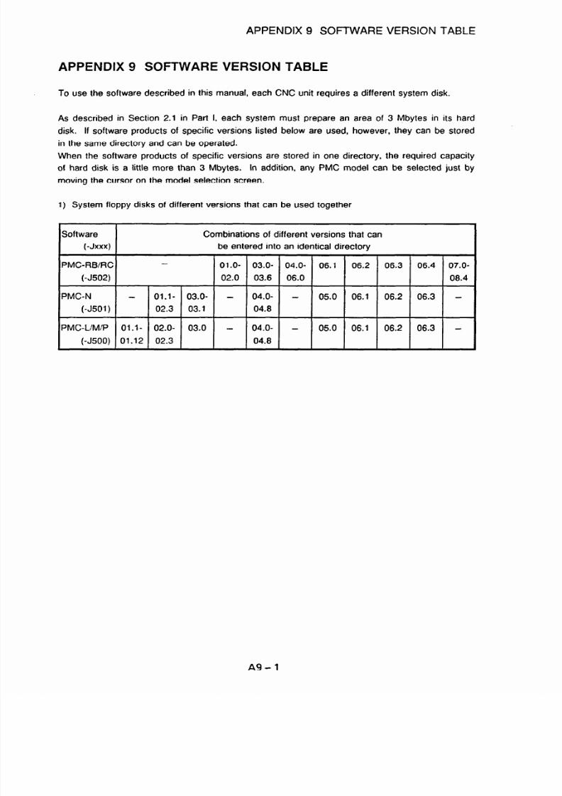
7/25/2019 FAPT Ladder for PC-Operator Manual
http://slidepdf.com/reader/full/fapt-ladder-for-pc-operator-manual 286/302
APPENDIX 9 SOFTWARE
APPENDIX 9 SOFTWARE VERSION TABLE
VERSION TABLE
To use the software described in this manual, each CNC unit requires a different system disk.
As described in Section 2.1 in Part I, each system must prepare an area of 3 Mbytes in its hard
disk. If software products of specific versions listed below are used, however, they can be stored
in the same directory and can be operated.
When the software products of specific versions are stored in one directory, the required capacity
of hard disk is a little more than 3 Mbytes. in addition, any PMC model can be selected just by
moving the cursor on the model selection screen.
1) System floppy disks of different versions that can be used together
Software
Combinations of different versions that can
(-Jxxx) be entered into an identical directory
PMC-FIB/FE Ol.O- 03.0- 04.0- 06.1
06.2 06.3 06.4 07.0-
(-J502) 02.0 03.6 06.0
08.4
PMC-N -
Ol.l- 03.0- - 04.0- -
05.0 06.1
06.2 06.3 -
(-J501) 02.3 03.1 04.8
PMC-L/M/P Ol.l- 02.0- 03.0 - 04.0- -
05.0 06.1 06.2 06.3 -
(-J500) 01.12 02.3 04.8
A9-1

7/25/2019 FAPT Ladder for PC-Operator Manual
http://slidepdf.com/reader/full/fapt-ladder-for-pc-operator-manual 287/302
APPENDIX 9 SOFTWARE VERSION TABLE
2) System floppy disks and module floppy disks for the FS16/18/15B,Powe Mate-D, F-D Mate Mini
that can be used together
software
(-Jxxx)
Combinations of versions
‘MC-RB/RC 01.0 02.0 03.0-03.6 04.0- 05.0- 06.1 06.2- 08.0- 08.3-
(-J502) 04.2 06.0 07.1 08.1 08.4
?Al/RA2 MODULE - 01.0 02.0 02.1 03.0- 04.0 04.1 04.2- 05.0 05.1
PMCRAl/RA2/RA3 03.4 04.4
PA1 /PA3)
(-J603)
IB/RC MODULE 01.0 02.0 03.0 03.1- 04.0- 04.5 04.7 04.8- 06.0 06.1
PMCRB/RB2/RB3 03.2 04.4 04.6 05.0
164/RC/RC3/RC4)
(-J604) (Note)
1C MODULE 01.0 01.1 01.2 02.0 02.1
(-J605)
JB MODULE 01.0 Ol.l- 02.0 02.1
(-J606) 01.2
Note) When using PMCRB4iRC4, install the RBI’RC MODULE floppy disk(-J604) at last of all
installation.
3)
System floppy disks and module floppy disks for the FSO,Power Mate-ABC
Software
I -J I
Combinations of versions
PMC-L/M/P 500 01 .l -04.8 05.0 06.1 06.2 -06.3
L MODULE 600 01.1-02.0 03.0 04.0 05.0-06.0
M MODULE 601 01.1-03.0 04.0 05.0 06.0 -07.0
M (MMC) MODULE 602 01 .l -02.0 03.0 04.0 05.0-06.0
Note) The column entitled -JXXX indicates the last three characters of software code A08B-
9200/9201 -JXXX
A9-2

7/25/2019 FAPT Ladder for PC-Operator Manual
http://slidepdf.com/reader/full/fapt-ladder-for-pc-operator-manual 288/302
APPENDIX 9 SOFTWARE VERSION TABLE
Software products listed in the same column can be stored in the same directory. When software
products to be stored in the same directory have the different version numbers, however, a
software product with a smaller number must be installed first. The following are examples:
1) Software products J502iO3.0 and JSOliO4.3 can be stored in the same directory. However,
J502/03.0
must be installed first.
2) Software products J502 03.0 and J501/03.0 cannot be stored in the same directory.
A9-3

7/25/2019 FAPT Ladder for PC-Operator Manual
http://slidepdf.com/reader/full/fapt-ladder-for-pc-operator-manual 289/302
APPENDIX IO MANAGING A SOURCE PROGRAM
APPENDIX IO MANAGING A SOURCE PROGRAM
1. TYPE OF SOURCE PROGRAM
There are two types of the source program of the following.
The file name and the control method are different though both are preserved as some files.
Especially, the function of ZOOM and G-SRCH can not be used at FORMAT-A but FORMAT-B.
1) FORMAT-A
The source program is managed using the following names. A single directory can contain two
or more source programs.
- xxxxxxxx.#CN :
File managing user programs
- xxxxxxxx.#PA :
File storing system parameters
- xxxxxxxx.#TA : File storing the title data
- xxxxxxxx.#sY :
File storing symbols
- xxxxxxxx.#c1 :
File storing comments
- xxxxxxxx.#c2 : File storing comments (reserve)
- xxxxxxxx.#ME :
File storing messages
- xxxxxxxx.#l0 :
File storing the I/O module data
- xxxxxxxx.#LA : File storing ladder
(xxxxxxxx is the specified source program name.)
2) FORMAT-B
A directory is created with the specified source program name. In the directory, the program is
managed under the following names. A single directory cannot contain two or more source
programs.
- CONTROL : File managing the source program
- SYSPARAM
: File storing system parameters
- TITLE
: File storing the title data
- SYMBOL : File storing symbols
- COMMENT1
: File storing comments
- COMMENT2 : File storing comments (reserve)
- MESSAGE : File storing messages
- IOMODULE : File storing the l/O module data
- LEVEL1 .#LA : File storing ladder of the first level
- LEVEL2.#LA : File storing ladder of the second level
- LEVEL3.#LA
: File storing ladder of the third level
- PYYYYY.#LA
: File storing ladder subprograms
- PYYYYY #SS
: File storing step sequence subprograms
(yyyyy is a subprogram number.)
A10-1

7/25/2019 FAPT Ladder for PC-Operator Manual
http://slidepdf.com/reader/full/fapt-ladder-for-pc-operator-manual 290/302

7/25/2019 FAPT Ladder for PC-Operator Manual
http://slidepdf.com/reader/full/fapt-ladder-for-pc-operator-manual 291/302
APPENDIX 10 MANAGING A SOURCE PROGRAM
3. SAMPLE MANAGEMENT OF FORMAT-C
The following functions have been added to PMCRB4RB4 (STEP SEQRCWRC4 (STEP SEQ.
The FORMAT-C source program is organized by below files.
<A case of specifying “C: y DATA y PRG C”
as source program >
-
C:Y
t
data Y
t
PRG CY
-CONTROL
- SYSPARAM
* TITLE
- XSYMBOL.xxx
- MESSAGE
- IOMODULE
* LEVEL1 #LA
* LEVEL2.#LA
* LEVELWLA
* Pyyy.#LA
- Pzzz.#SS
. NETCMT.xxx
* OPTION
- * MCARD
Source program managing file
System parameter data file
Title data file
Symbol & Comment data file
Message data file
I/O Module data file
First level ladder data file
Second level ladder data file
Third level ladder data file
Sub-program ladder data file
Sub-program step sequence data file
Net comment data file
Setting of option
Memory card syste file
(Note
1)
(Note 2)
(Note 3)
(Note 3)
(Note 1)
(Notel)
(Note2)
(Note3)
‘xxx’ is number of multi file managing.
Only for use LEVEL3 ladder at PMCRC4IRC4(STEP).
‘yyy’, ‘zzz’ is number of sub-program.
The format
of newly created source program is specified by ‘%%%FLSET.CNF data file. The
initial settings for RB4 RB4(STEP)/RC4/RC4(STEP) are FORMAT-C.
Data file name : %%%FLSET.CNF
7;
Source program type
kB4
3;
RB4 STEP :3;
RC4- =3;
RC4_STEP = 3;
Parameters’ value
‘1’ = FORMAT-A
‘3’ = FORMAT-C (initial setting)
A10-3

7/25/2019 FAPT Ladder for PC-Operator Manual
http://slidepdf.com/reader/full/fapt-ladder-for-pc-operator-manual 292/302
APPENDIX
10
MANAGING A SOURCE PROGRAM
4. SOURCE PROGRAM TYPE AND PMC MODEL
The source program type is decided by setting the PMC model.
1) FORMAT-A.
- PMCRC/RC3’RBiRB2/RB3.:RAl/RA2/RA3
- PMC-NBQC
* PMCPAl PA3
*
PMC-N’N (10 LINK)/QA
- PMC-L’MIM (MMC)
- PMC-RB4/RC4(A08B-9200/9201 -Jr502 ver.8.0 or earlier)
2) FORMAT-B
- PMCRB4 (STEP SEQ)/RC4 (STEP SEQ) (A08B-9200/9201-J502 Ver. 8.1, 8.2, 8.3)
- PMC-RB4/RC4 (A08B-9200 9201-J502 ver.8.0, 8.2, 8.3)
3) FORMAT-C
-
PMCRB4.‘RB4 (STEP SEQ)IRCWRC4(STEP SEQ) (A08B-9200/9201-J502 Ver 8.4 or later)
* PMC-RBMRBG NB2
Note) In case of PMCRBWRC4, FAPT LADDER creates two types of source program as above
mentioned. Therefore, the source program of ver.8.0 needs conversion for using on
ver.8.1.
For the operation of conversion refer to next chapter “6.4 Conversion from FORMAT-A to
FORMAT-B”
A10-4

7/25/2019 FAPT Ladder for PC-Operator Manual
http://slidepdf.com/reader/full/fapt-ladder-for-pc-operator-manual 293/302
APPENDIX 10 MANAGING A SOURCE PROGRAM
5. CONVERSION FROM FORMAT-A TO FORMAT-B
When FAPT LADDER for PMC-RB4iRC4(A08B-9200 9201-J502) is updated from ver.8.0 or earlier
to ver.8.1 or later, it needs source program conversion.
The operation is the following.
1) Convert the source program “FORMAT-A” into an all-format mnemonic data with FAPT
LADDER(A08B-9200 9201-J502) ver.8.1 or later.
2) Convert the mnemonic data into a source program with the same FAPR LADDER.
The conversion is completed by above mentioned.
In case of using a control statement file, which has extension
“.#I.$‘, for combining modules, the
operation is the following.
- Do the operation of 1) by each source program in the control statement.
- Combine each mnemonic data into an all-format mnemonic data.
- Do the operation of 2).
Note) It is possible to use FORMAT-A without conversion. In that case, you need to modify a
“%%%FLSET.CNF”. But it is not recommended.
For the
“%%%FLSET.CNF” refer to the “APPENDIX 7 System configuration file
“%%%FLSET.CNF”.
6. COPYING AND MOVING A SOURCE PROGRAM
FAPT LADDER does not support a function to enable the copying or moving of a source program.
Because the source program is managed as described above, it can be copied or moved by using
file manipulation on a specified directory with the COPY or another MS-DOS command. Only
programs for an identical model can be handled in this way.
For example, to make a backup copy on floppy disk of the source program shown above, enter the
following command at the MS-DOS prompt:
1) Suppose that the floppy disk drive is B:.
2) Create a source program storage directory on B:.
A > MKDIR B: +r BACKUP [RET]
3) Copy all files under the directories specified with the source program name.
The source program is copied.
To edit the copied source program, start FAPT LADDER and specify B:Y BACKUP as the source
program name.
A10-5
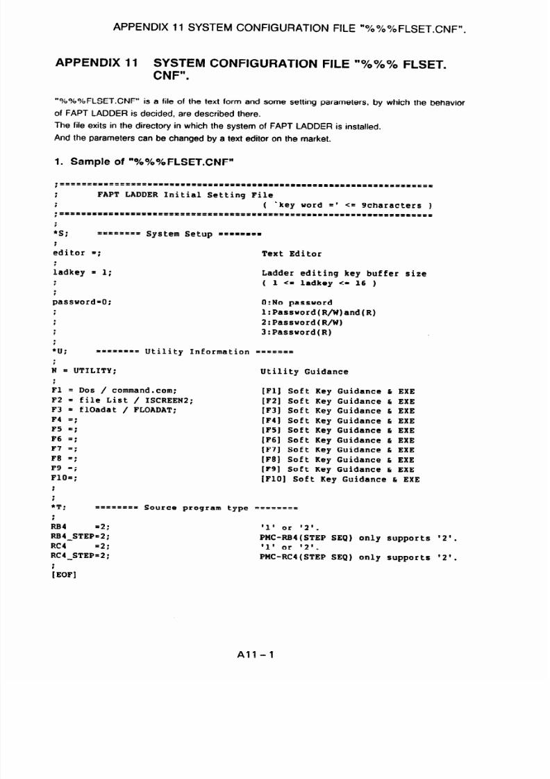
7/25/2019 FAPT Ladder for PC-Operator Manual
http://slidepdf.com/reader/full/fapt-ladder-for-pc-operator-manual 294/302
APPENDIX
11
SYSTEM CONFIGURATION FILE “%%%FLSET.CNF”.
APPENDIX 11
SYSTEM CONFIGURATION FILE “%%% FLSET.
CNF”.
“%%%FLSET.CNF” is a file of the text form and some setting parameters, by
of FAPT LADDER is decided, are described there.
The file exits in the directory in which the system of FAPT LADDER is installed.
And the parameters can be changed by a text editor on the market.
1. Sample of “%%%FLSET.CNF”
which the behavior
;IIIII=t trrfllll’llllllltlll’1111111111111110
IPttLtllLlDlttPOltt=It
:
FAPT LADDER Initial Setting File
t
( 'key word =' <= Scharactets )
;rPlrllLIIDl====ltll
IILDIIIILrt=rlllllPL-======-=
Illll'llttllllltlll=
f
:
=t=tff== System Setup ====t===
:
editor =;
Text Editor
:
ladkey = 1;
Ladder editing key buffer size
;
( 1 <= ladkey <- 16 )
:
password=O; 0:No password
:
l:Password(R/W)and(R)
f
2:Password(R/W)
;
3:Password(R)
i
:
===f==== Utility Information ==t====
:
N = UTILITY;
Utility Guidance
i
Fl
= DOS /
command.com;
F2 = file List / ISCREENZ;
F3 = flOadat / FLOADAT;
F4 =;
F5 =;
F6 =;
F7 =;
F =;
F9 =;
FlO=;
[Fl] Soft Key Guidance 6 EXE
[FZ] Soft Key Guidance h EXE
(F3) Soft Key Guidance 6 EXE
[F4] Soft Key Guidance L EXE
[FSJ Soft Key Guidance C EXE
[F6] Soft Key Guidance h EXE
[F7] Soft Key Guidance 6 EXE
[FE]
Soft Key Guidance 6 EXE
[F9] Soft Key Guidance & EXE
[FlO] Soft Key Guidance 6 EXE
i
:
*T;
======== Source program type r=======
.
LB4
'2;
'1' or '2'.
RB4_STEP=2;
PMC+B4(STEP SEQ) only supports
RC4
'2;
'1' or '2'.
RC4_STEP=2;
PMC-RCI(STEP SEQ) only supports
'2'.
'2'.
i
IEOFI
All-l

7/25/2019 FAPT Ladder for PC-Operator Manual
http://slidepdf.com/reader/full/fapt-ladder-for-pc-operator-manual 295/302
APPENDIX 11 SYSTEM CONFIGURATION FILE “%%% FLSET.CNF”.
All parameters in the “%%%FLSET.CNF” are described following the form of “key word = “.
Hereafter, content of setting parameters is explained by each item.
1) Specification of source program type
a)
W
Function
FAPT LADDER will newly create the source program at “conversion of mnemonic ->
source”,
“editing new source program” and “decompilation”.
The type of created source program is decided at this time.
key word
By each PMC model, a setting parameter will be described succeeding the line of ‘I* T;
=========
Source program type = = = = = = = = “.
Key word shows the model and uses the same character string as the display of model
information on the status line displayed in each screen of FAPT LADDER.
This setting is effective only in case of Key word “RB4 = “,” RC4 = “.
As for the value, either
"1"
or “2” is effective.
_ . I w
1 = FORMAT-A
- “2”
= FORMAT-B
It is FORMAT-B in initialization. When the source program type is FORMAT-B, the function
of “ZOOM” and “G-SRCH” can be used.
All
-2

7/25/2019 FAPT Ladder for PC-Operator Manual
http://slidepdf.com/reader/full/fapt-ladder-for-pc-operator-manual 296/302
APPENDIX 12 INQUIRY FORM
APPENDIX 12 INQUIRY FORM
Comoanv name Section
Person in charqe Phone No. ( 1
Address
Fax No.
t )
FANUC
sales person
No.
Product name
Ordering code
2
3
4
5
[Usage environment]
Machine tvpe used (PC)
DOS MS-DOS
Version
(Manufacturer:
(Manufacturer:
EMS board:
Yes I No (Manufacturer:
1
Other equipment (printer, etc.) (Manufacturer:
1
Please print out the CONFIG.SYS and AUTOEXECBAT files on a sheet and attach it to this form.
[Details of inquiry]
Please use this form when you have any questions about this product.
AlZ-1

7/25/2019 FAPT Ladder for PC-Operator Manual
http://slidepdf.com/reader/full/fapt-ladder-for-pc-operator-manual 297/302
INDEX
(PMC-RA~/RA~/RB~/RB~/RB~ RB~ RC~/RC~/NB NB~) . . . . . . . . . . . . . . . . . . . . . .
1 - 99
A Program Configuration Screen . . . . . . . . . . . . . . . . . . . . . . . . . . . . . . . . . . . . . . . 3 - 1
ACTIVATION . . . . . . . . . . . . . . . . . . . . . . . . . . . . . . . . . . . . . . . . . . . . . . . . . . . . l-15
<B>
BASICOPERATION ...............................................
l-17
Basic Operation
...................................................
3 - 6
BOOT SYSTEM OPERATING PROCEDURE (FOR THE FS20) ................ A5 - 1
BUSY
control
....................................................
2 - 4
<c>
CAUTIONS FOR USING THE O/S ............................. ........ A7 - 1
Changing Printer Output Format ............................. ......... 2 - 12
Changing the Order of Subprograms .............................. ....
l- 103
Changing the paper selection name
....................................
2 - 14
Command input during startup
........................................
2 - 1
COMMON OPERATIONS FOR THE PC9801 AND IBM PC/AT .................. 2 - 1
Common System Operations
........................................
1 - 19
Communications settings
............................................
2 - 2
Compilation ..................................................... 1 - 94
Conversion of a mnemonic file to a source program .......................
1 - 152
Conversion of a source program to a mnemonic file .......................
l-150
Convert the PMC Type of Sequence Program
.............................
2 - 8
Convert with signal address converter
...................................
2 - 9
Converting a step sequence program according to the model ................. 1 - 113
Converting by system parameter editing ........................... ....... 2 - 8
Creating a step sequence program
....................................
3 - 10
Creating a Step Sequence
...........................................
3 - 9
Creating a subprogram of the step sequence
..............................
3 - 9
Data conversion (return codes) .............................. .......... 2 - 5
DataFlow ............................... ........................ 3-3
Data start and end codes ............................... ............. 2-5
DATATRANSFERCABLES ............................ ............. Al-l
Decompilation ..................................................
l-110
DOScommand .................................................
l-109
<E>
Editing . . . . . . . . . . . . . . . . . . . . . . . . . . . . . . . . . . . . . . . . . . . . . . . . . . . . . . . .
1-22
EDITING . . . . . . . . . . . . . . . . . . . . . . . . . . . . . . . . . . . . . . . . . . . . . . . . . . . . . . . .
3-6

7/25/2019 FAPT Ladder for PC-Operator Manual
http://slidepdf.com/reader/full/fapt-ladder-for-pc-operator-manual 298/302
Error detection and handling
..........................................
2 - 7
Error detection and messages ........................... .............. 2 - 6
ERROR MESSAGES
..............................................
A3 -
1
<F>
FLOPPY CASSETTE ADAPTER + 3.5” floppy disk (P-G format) ...............
1 - 149
FUNCTION FOR OPERATING THE PMC-UM WITH RAM .................... A2 - 1
Function for Transferring Data between the P-G and PC ...................... 2 - 1
<H>
Handy File + 3.5” floppy disk (MS-DOS format) . . . . . . . . . . . . . . . . . . . . . . . . . . .
l-147
l/O module editing ............................ ....................
l-70
IBM PC/AT operating environment ........................... .......... l-10
Input/Output for PMC-QA (FANUC SYSTEM F-MODEL D Mate) ...............
l-134
Input/Output ...................................................
1-119
INQUIRYFORM ................................................
A12- 1
Installation Procedure ............................ ..................
l-11
INSTALLATION ............................ ....................... 1-5
It is possible to choose output data (SymbolComment, Net comment) to ROM format file1 - 103
<I_>
Ladder diagram editing . . . . . . . . . . . . . . . . . . . . . . . . . . . . . . . . . . . . . . . . . . . . l-26
Link . . . . . . . . . . . . . . . . . . . . . . . . . . . . . . . . . . . . . . . . . . . . . . . . . . . . . . . . .
1-116
MANAGING A SOURCE PROGRAM
..................................
MEMORY CARD COMPATIBILITY (FOR THE PMCRAl/RA3, NB, AND QC)
......
Memory card interface in the personal computer and memory card
.............
Menu Configuration ............................ ...................
Merge ........................................................
Message editing
.................................................
Mnemonic Editing
...............................................
Mnemonic file format
.............................................
Model Setting ...................................................
MODULAR PROGRAMMING (PMC-RA3/RB3/RC3 ONLY)
....................
AlO- 1
A6-1
1-142
1-17
1-113
l-68
l-150
l-153
l-21
A4-1
co>
Operating Environment
..............................................
1 - 6
OPERATION ....................................................
l-22
Operation
..............................................
1 - 95, l-110,3-4
Outputting to split files
............................................
1-112
OVERVIEW
...................................................
1 - 1,3-l

7/25/2019 FAPT Ladder for PC-Operator Manual
http://slidepdf.com/reader/full/fapt-ladder-for-pc-operator-manual 299/302
<P>
Password set function
PC9801 operating environment
. . . . . . . . . . . . . . . . . . . . . . . . . . . . . . . . . . . . . . .
1 - 7
Printout . . . . . . . . . . . . . . . . . . . . . . . . . . . . . . . . . . . . . . . . . . . . . . . . . . . . . . . .
l-85
Programming with the Step Sequence Method . . . . . . . . . . . . . . . . . . . . . . . . . . . . . 3 - 1
Protocol
. . . . . . . . . . . . . . . . . . . . . . . . . . . . . . . . . . . . . . . . . . . . . . . . . . . . . . . .
2-4
ROM writers (PMC writer, FA writer)
. . . . . . . . . . . . . . . . . . . . . . . . . . . . . . . . . .
l-122
<s>
Sample mnemonic files (all-format)
...................................
Sample mnemonic files (single-format)
.................................
SETTINGAMODEL
...............................................
Setting form feed .................................................
Setting line feed
.................................................
Setting the cross-reference list output format guidance information
..............
Setting the cross-reference list output information
..........................
Setting the cross-reference list read/write coil guidance information
.............
Setting the left margin
.............................................
Setting the line spacing
............................................
Setting the output format guidance
....................................
Setting the output format
...........................................
Setting the output information
........................................
Setting the printer model and print paper ................................
Setting the read/write coil guidance
....................................
Setting the spacing between the LADDER net
............................
Setting the title of printout
...........................................
Setting the top margin
.............................................
SOFTWARE VERSION TABLE
.......................................
Specifying the cross-reference list linefeed
...............................
Specifying the cross-reference list output format
...........................
Specifying the cross-reference list page break
............................
Standard Symbol Data
.............................................
Symbol and comment editing ........................................
SYSTEM CONFIGURATION FILE “%%% FLSET.CNF.”
.....................
System parameter editing
..........................................
1-166
l-157
3-4
2-23
2-23
2-19
2-20
2-21
2-16
2-16
2-22
2-22
2-22
2-15
2-23
2- 14
2- 19
2-14
A9-1
2-21
2-20
2-21
2-11
l-60
All-l
l-73
<T>
The Configration of a Sequence Program
.................................
3 - 2
The list of source program
.........................................
l-105
The note if the step sequence function is selected when setting a model
........
l-170
Title data editing
.................................................
l-25
TOOL FOR CHANGING MESSAGE DATA (CHGMES)
......................
A8 - 1
Transfer to and from PMC-UM (FANUC Series 0)
.........................
l-124
Transfer to and from PMC-N/NA (FANUC Series 15-MODEL A, -MODEL B)
...... l-131

7/25/2019 FAPT Ladder for PC-Operator Manual
http://slidepdf.com/reader/full/fapt-ladder-for-pc-operator-manual 300/302

7/25/2019 FAPT Ladder for PC-Operator Manual
http://slidepdf.com/reader/full/fapt-ladder-for-pc-operator-manual 301/302
Revision Record
FAPT LADDER (For Personal Computer) OPERATOR’S MANUAL (B-66131 E
5 Dec., 95
- Corresponding descriptions for PMC-RBSIRBGiNB2
04
*
Addition of PMC-MODEL RA3/RB3/FKX/PAl/PA3/QC/NB
.
Addition of symbol and comment edit function on Ladder Edit
screen
Jun., ‘93
*
Addition of external ROM format file conversion function
*
Addition of cross reference print format setting function
.
Addition of mnemonic edit label/subprogram Item
.
Change of symbol and comment edit function
03
Dec., ‘92
Correction of errors
02 Sep., ‘92
Total revision
01 Jun., ‘90
Edition Date
Contents
Edition
Date Contents

7/25/2019 FAPT Ladder for PC-Operator Manual
http://slidepdf.com/reader/full/fapt-ladder-for-pc-operator-manual 302/302
Top Related