![· What do you understand by commutation of SCR. Explain class C commutation with the help of waveforms. Design the biggening circuit for SCR using U] T. The UJT ...](https://static.fdocuments.us/doc/165x107/5acf08ec7f8b9ad24f8bf205/do-you-understand-by-commutation-of-scr-explain-class-c-commutation-with-the-help.jpg)


Languages
Pages
Legal


1
FACULTY OF ENGINEERING
UNIVERSITY OF LUCKNOW Second Campus, Jankipuram, Lucknow-226031 (U.P.)
TENDER NOTICE
The University of Lucknow, Lucknow invites sealed tender from eligible bidders for supply testing and commissioning of Equipments for Electrical Engineering laboratories of Faculty of Engineering, University of Lucknow, Second Campus, Jankipuram, Lucknow-226031 (U.P.). Separate tenders must be submitted at University of Lucknow for each package of following Electrical Engineering Laboratories:
Package – FOE/EE/01/2019 - Power Electronics Laboratory Package – FOE/EE/02/2019 - Control System Laboratory Package – FOE/EE/03/2019 - Power System Laboratory – I Package – FOE/EE/04/2019 - Power System Laboratory – II Package - FOE/EE/05/2019 - Electrical Design & Fabrication Laboratory
For Tender Documents, Tender Cost, EMD, Specifications of equipments and other details please visit our website: www.lkouni.ac.in
REGISTRAR
University of Lucknow

2
FACULTY OF ENGINEERING UNIVERSITY OF LUCKNOW
Second Campus, Jankipuram, Lucknow-226031 (U.P.)
TENDER DOCUMENT
Tender No. - 03/FOE/LU/2019 Date:
Sealed and separate tenders in two parts i.e. tender bid-I (Technical) and tender bid-II (Financial) are herewith invited for Supply & Commissioning of Electrical Engineering Laboratory
Equipments at Faculty of Engineering, University of Lucknow, Second Campus, Jankipuram, Lucknow-226031 (U.P.), along with Earnest money (Mentioned with package/unit) in the shape of Demand Draft of Nationalized Bank in favour of Finance Officer, University of Lucknow, Luckow (U.P.). Both envelopes should be kept in one big envelope. The tender should reach to the undersigned latest 20.06.2019 at 02.00 PM.
Terms & Conditions
1. Tenders are being invited for purchase and commissioning of equipments to establish various laboratories. Each Laboratory will be treated as one package/unit. It is obligatory that a firm selected for the establishment of a Laboratory shall supply all the equipments of that laboratory. The firm will also complete the work of installation/mounting and commissioning of these equipments.
2. Bid Evaluation Criteria: Bid shall be evaluated for whole package. 3. Details of equipments/materials are as per bill of quantity attached. 4. Tenders should be submitted either in person or by post in sealed envelopes on which name
of package/unit, tender number and date along with name and address of the firm will be written.
5. TENDER BID-I (Technical) shall contain (i) Tender cost (non refundable) (ii) Earnest Money (iii) Proof of PAN and GST registration documents (iv) Standing of the firm (v) Major supplies executed in recent past (vi) Authorized dealer certificate from OEM & Commercial terms and conditions. TENDER BID-II (Financial) shall contain rate schedule only. The rates per unit must be quoted both in figures and words. Any overwriting and/or cutting must be duly signed failing which tenders are likely to be rejected.
6. Tenders received after due date and time will not be considered. 7. EMD of all unsuccessful bidders will be refunded after opening of tenders. However, EMD of
successful bidder will be refunded only after successful installation and commissioning of equipments and due verification by concerned authority.
8. DD of Rs. 1000-/- being cost of tender per package has to be attached with Tender form in favour of Finance Officer, University of Lucknow payable at Lucknow, which is not refundable in any case.
9. Price quoted should be F.O.R. Faculty of Engineering, University of Lucknow, Second Campus, Jankipuram, Lucknow-226031 (U.P.).

3
10. Minimum turnover of the firm should be one crore per year (enclosed certificate).11. The firm should have wide experience of similar work executed during last three years in
academic institutions. The proof for the same should be attached.12. Detailed specifications and make of the equipments/ materials must be given.13. All available technical literature, catalogues and other data sheets in support of the
Specifications and details of the items should be furnished along with the technical bid.14. All the supplied equipment must have minimum warranty of one year on site from the Date of
installation and acceptance by Faculty of Engineering, University of Lucknow.15. Quoted items should be strictly in order of merit with serial number and metric unit otherwise
the tenders are liable to be ignored.16. Conditions regarding validity of tenders, delivery period, payment discount, warrantee and
guarantee period, GST, custom duty and insurance etc. should be mentioned clearly. Netprices should be quoted.
17. No sales tax form “CZX” or ‘D” etc. for concessional rates shall be provided by the University.18. Quoted rates should be valid for at least six months from the date of opening of tender.19. Tenders without sample wherever required may not be accepted.20. In case of imported equipments, commission allowed to agents must be specifically
mentioned.21. The equipments manufactured in China will not be accepted.22. Free demonstration shall be done in the University premises if required.23. Insurance during transport shall be done by the suppliers at their own cost.24. Tenders without mentioned earnest money deposit will not be entertained.25. Standing of the firm and major supplies carried out in recent past with proof must be
attached.26. In case of dealers, authorized distributors, dealer’s certificate from OEM is required27. Document through bank and advance payment on proforma invoice shall not be accepted.28. The items and quantity mentioned in bill of quantity against each item will be treated as
provisional and it may be changed depending on actual requirement.29. Payment will be made only after successful installation and commissioning of equipments in
the concerned Laboratory and due verification by concerned authority.30. If the supply is not made within one month, the firm shall be liable to pay a penalty equal to
0.10% of value of purchase order per day. However this can be waved off by the Hon’ble ViceChancellor under special circumstances. If the firm fails to supply the equipments the earnestmoney deposit will be forfeited.
31. Deduction of TDS as per Govt. Rules.32. Tenders will be opened in the presence of Tender Committee and bidders or their authorized
representatives who wish to be present on the date of opening.33. Any dispute will be subject to Lucknow (U.P.), Jurisdiction only.34. Conditional tenders will not be accepted.35. Authorized signatory has to keep all the original documents at the time of opening of tender.36. The Vice-Chancellor has the right to accept or reject any or all tenders without assigning any
reason.I/We have read and understood the above conditions and agree to abide by them.
Authorized Signatory & Seal of the Bidder/Proprietor

5
FACULTY OF ENGINEERING
UNIVERSITY OF LUCKNOW Second Campus, Jankipuram, Lucknow-226031 (U.P.)
TENDER BID-I (Technical) Tender
Purchase and Commissioning of Equipments for Electrical Engineering Laboratories
Package No.
Name of the firm with full address and contact number
For Faculty of Engineering, University of Lucknow, Second Campus, Jankipuram, Lucknow-226031 (U.P.)
Cost of Tender Document DD No: Amount: Bank: Date: Drawn in favour of Finance Officer, University of Lucknow, payable at Luckow (U.P.).
Earnest Money Deposit DD No: Amount: Bank: Date: Drawn in favour of Finance Officer, University of Lucknow, payable at Luckow (U.P.).
PAN/GST No PAN GST (Attach proof)
Income Tax Return of last three years
Attach Copy
Original Equipment Manufacturers/Authorization Letter from O.E.M.
Attach proof
Turnover in the last three years
Attach proof
Details of Similar Work Executed during last Three years in academic institution
Attach proof
Place of Tender Submission Proctor Office, University of Lucknow, Old Campus, Lucknow- 226 007 (U.P.)
Last Date of Tender Submission
Date:- 20.06.2019 Time:- 02.00 PM
Place of Tender Opening Registrar Office, Committee Room, Lucknow University (Old Campus), Lucknow.
Opening of Tender Date:- 21.06.2019 Time:- 02.00 PM
Signature and Seal of Bidders

6
TENDER BID-II (Financial)
Package-FOE/EE/01: Power Electronics Laboratory
Tender Cost: Rs. 1000/-+ Rs. 180 GST EMD: Rs. 9,000=00
Bill of Quantity
S.No. NAME OF EQUIPMENT QTY. Unit
Cost
Total Cost
1. Complete Setup For performing :-
To study V-I characteristics of SCR and measure latching
and holding currents. Complete setup with digital
measuring instruments.
Demonstration board with following facilities :-
(a) Isolated 0-230 V DC variable source – 1 Set
(b) Isolated 0-600 V DC variable source – 1 Set
(c) Isolated 0-12 V DC variable source – 2 Sets
(d) External Load – 3 Nos.
(e) SCR
Multimeter
Lamp 15 Watt 230 V – 2 Nos.
Demonstration Board Cover.
To conduct SCR Shorted gate experiment
To conduct biased (Forward & Reverse) gate SCR
firing experiments
Set of Patch Chords & Manual.
02
2. Complete Setup For performing :-
To study R, RC and UJT trigger circuit for SCR.
Setup will consists of :-
Demonstration Board with following facilities :-
(a) Isolated AC 230 V & 14 V Supply
(b) 10:1 Resistive Attenuator for observation on CRO.
(c) Fuse for short circuit protection.
25 Watt 250 V Lamp.
Demonstration Board Cover
R, RC and UJT Triggering circuits
Set of Patch Chords & Manual
02
3. Complete Setup For performing :-
To study the various commutation circuits for SCR.
Demonstration Board with following facilities :-
(a) Isolated DC 230 V.
(b) Isolated DC 30 V.
(c) Pulse Frequency Generator
(d) External Load (Lamp Load)
(e) 10:1 Resistive Attenuator for observation of CRO
(f) 3A Fuse for short circuit protection.
02

7
15 Watt 250 V Lamp.
Demonstration Board Cover
Auxiliary Commutation Circuit
Resonant Commutation Circuit
Complimentary Commutation Circuit
Set of Patch Chords & Manual
4. Complete Setup For performing :-
To study single-phase half wave controlled rectifier with (i)
resistive load (ii) inductive load with and without
freewheeling diode.
The setup is provided with isolation transformer for C.R.O.
protections and lamp bank.
1. Demonstration Board with following facilities :-
(a) Single Phase Half Controlled Bridge
(b) Firing Pulse Generator
(c) Resistive Load (Lamp)
(d) Inductive Load (Choke)
(e) Voltmeter 0-300V
(f) Ammeter 0-5A
(g) 1:10 Attenuator for CRO
(h) Isolated 220 V AC for CRO
2. DC Motor 1 HP
3. Connecting Leads
4. Lamp Holder
5. Lamp 250 Volts
Complete experimental setup with DC Motor & Engraved
Panel board with Banana Sockets for ease of connections
by students
01
5. Complete Setup For performing :-
To study single phase (i) fully controlled (ii) half controlled
bridge rectifiers with resistive and Inductive loads.
Features :-
230V, AC Isolated Transformer, Power 50 Watt
9V DC at 100 mA Zener Regulated Power Supply
Two UJT.
Two Pulse Transformer1:1:1.
Two Potentiometers for controlling UJT firing angle.
Bulb 40W, 230 AC
Adequate no of others Electronics Components.
02
6. Complete Setup For performing :-
To study three-phase fully/half controlled bridge rectifier
with resistive and inductive loads.
Features :-
Three Phase line commuted fully-controlled
thyristorized bridge converter.
Miniature Circuit Breaker (MCB).
Three cards consisting of Zero Crossing Detector,
Integrator, Comparator and Pulse Generator one for
each phase, for controlling thyristors. Another card in
01

8
conjunction with above three cards for controlling the
triggering angles of the negative group of three
thyristors.
Firing angle control potentiometer.
415:50V transformer for rectification and low voltage
AC supply for triggering.
12V at 500mA power supply for triggering circuit.
Driver Circuits with Pulse Transformer: 06 No.
R & L load with Load voltage divider.
Panel meter for measurement of voltage & current.
Freewheel diode: 01 No.
Unearthed mains sockets for CRO.
7. Complete Setup For performing :-
To study TRIAC based single-phase ac voltage regulator
and determination of thyristor switching characteristics
and pulse transformer characteristics.
.Complete setup with fraction Horse Power Motor.
AC Phase Control training unit with following
facilities :-
(a) Isolated 230 V or 50 V supply
(b) Fuse for Short Circuit protection
(c) AC Phase control by RC Triggering
(d) AC Phase Control by UJT Triggering
(e) 10:1 Potential Divider for CRO
Protection Cover - 1 No.
Lamp 25 Watt, 230 V - 1 No.
Set of Patch Chords & Manual.
Complete setup with Motor
02
8. Complete Setup For performing :-
To study single phase cyclo-converter
The experimental setup consists of :-
(i) Power Circuit consisting of two fully controlled Bridge
Converter connected in anti parallel (Bridges P & N).
Bridge P supplies load current in the positive half of output
cycle and bridge N provides load current in the negative
half of output cycle.
(ii) Firing Circuit consists of Micro Controller Based Firing
Unit which provides Isolated Gate pulses through pulse
transformers separately for P & N Bridges. Toggle switch is
provided to select the output frequency (1/1f, 1/2f, 1/3f,
1/4f, 1/5f). Firing angle can be changed either :-
a) through toggle switches for increasing and decreasing of
firing angle. Firing angle during all half cycles of AC input
supply remains same in this mode of control.
b) through serial port of computer by connector provided on
the experimental kit to the serial port of computer and then
entering the firing angle to the key board.
In this mode of control the firing angle of each half cycle of
input supply can be independently controlled.
01

9
(iii) Patch Cord.
(iv) Instruction Manual
9. Complete Setup For performing :-
To study triggering of (i) IGBT (ii) MOSFET (iii) power
transistor.
1. Complete experimental setup consisting demonstration
Board with following facilities :-
(a) 110 V DC Supply
(b) Different testing points
(c) 1:10 Attenuator for CRO
(d) Triggering Generator
(e) IGBT, MOSFET & Power Transistor
2. Lamp 15 Watt 250V
3. Connecting Leads
02
10. Complete Setup For performing :-
To study four quadrant operation of IGBT/MOSFET
chopper circuit.
This is DC chopper circuit for getting a variable DC voltage
by using on time control and frequency control to feed DC-
motor (Universal Motor). Circuit demonstrate the use of
smooth speed variation with the help of chopper circuit and
test points are provided.
1. Demonstration Board with following facilities :-
(a) 110 V DC Supply
(b) Different testing points
(c) 1:10 Attenuator for CRO
(d) DC Voltmeter
(e) DC Amp Meter
2. Lamp 60 Watt 250V
3. Connecting Leads
01
11. Complete Setup For performing :-
To study MOSFET/IGBT based single-phase series-
resonant inverter.
Complete experimental setup consisting of :-
1. Demonstration Board with following facilities :-
(a) Isolated DC 110 V
(b) Isolated Gate Frequency
(c) External Load
(d) 200 W Lamp for Short Circuit Protection
(e) 1:10 Resistive Attenuator
(f) 1A Fuse for short circuit protection.
2. Demonstration Board Cover
3. Patch Cords
All the circuit diagram and necessary test point are clearly
marked on Engraved front panel for education study
purpose.
01
12. Complete Setup For performing :-
To study MOSFET/IGBT based single-phase bridge
inverter.
Consisting of :-
01

10
1. Demonstration Board with following facilities :-
(a) Isolated DC 110 V.
(b) Isolated Gate Frequency
(c) External Load
(d) 200 W Lamp for Short Circuit Protection
(e) 1:10 Resistive Attenuator
(f) 1A Fuse for short circuit protection.
2. Demonstration Board Cover
3. Patch Cords
All the circuit diagram and necessary test point are clearly
marked on Engraved front panel for education study
purpose.
13. CRO 30 MHZ Dual Channel, DC to 30 MHz, Invert facility in both
Channels
Vertical Deflection coefficients: 5 mV to 20 V/div.
Time Base: 20 ns -0.2 s/ div; Variable Hold- Off; X10
Magnification
Triggering: DC-60 MHz; Active TV Sync Sep.;
Alternate triggering
LED indication for stable triggering
XY mode
Z Modulation
Saw tooth output (5 Vpp approx )
Component Tester; 2 Level Calibrator
05
Total
Note: Provide all the required measuring instruments for each setup.
11
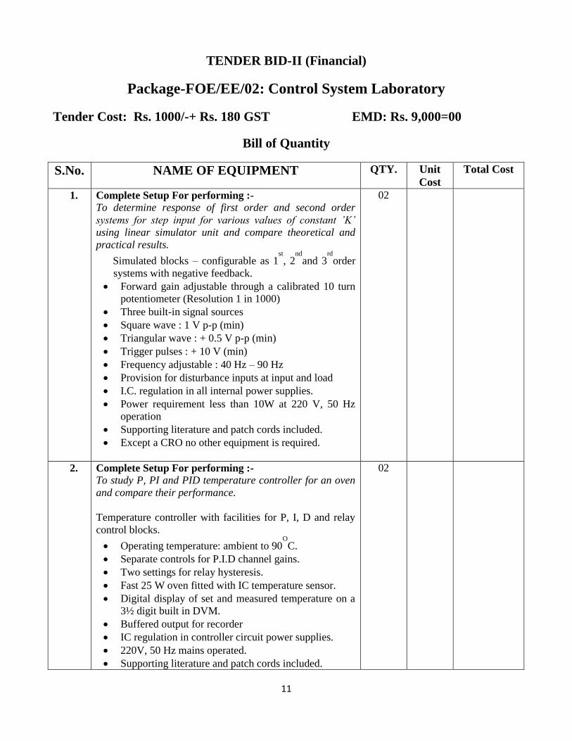
TENDER BID-II (Financial)
Package-FOE/EE/02: Control System Laboratory
Tender Cost: Rs. 1000/-+ Rs. 180 GST EMD: Rs. 9,000=00
Bill of Quantity
S.No. NAME OF EQUIPMENT QTY. Unit
Cost
Total Cost
1. Complete Setup For performing :- To determine response of first order and second order
systems for step input for various values of constant ’K’
using linear simulator unit and compare theoretical and
practical results.
Simulated blocks – configurable as 1st
, 2nd
and 3rd
order
systems with negative feedback.
Forward gain adjustable through a calibrated 10 turn
potentiometer (Resolution 1 in 1000)
Three built-in signal sources
Square wave : 1 V p-p (min)
Triangular wave : + 0.5 V p-p (min)
Trigger pulses : + 10 V (min)
Frequency adjustable : 40 Hz – 90 Hz
Provision for disturbance inputs at input and load
I.C. regulation in all internal power supplies.
Power requirement less than 10W at 220 V, 50 Hz
operation
Supporting literature and patch cords included.
Except a CRO no other equipment is required.
02
2. Complete Setup For performing :- To study P, PI and PID temperature controller for an oven
and compare their performance.
Temperature controller with facilities for P, I, D and relay
control blocks.
Operating temperature: ambient to 90O
C.
Separate controls for P.I.D channel gains.
Two settings for relay hysteresis.
Fast 25 W oven fitted with IC temperature sensor.
Digital display of set and measured temperature on a
3½ digit built in DVM.
Buffered output for recorder
IC regulation in controller circuit power supplies.
220V, 50 Hz mains operated.
Supporting literature and patch cords included.
02

12
3. Complete Setup For performing :- To study the potentiometer as error detector for DC/AC
excitation.
Complete experimental setup consisting of :-
Potentiometer: Two high quality servo potentiometers
360° Mechanical, 350° Electrical span with 1°resolution
dials.
Type of operation: DC and AC signal operation
Display: 3.5 Digital Panel Meter for measurements
Excitation: IC regulated DC excitation for both
potentiometers (DC operation). AC excitation at 400 Hz
approx. (AC operation).
Balanced Demodulator: Built in demodulator circuit
(balanced demodulator) for C.R.O. Observation.
Power supply: Built in IC regulated power supplies
Cabinet: Housed in rigid MS powder coated with moulded
frame.
01
4. Complete Setup For performing :- To study and calibrate temperature using resistance
temperature detector (RTD)
Using Temperature sensor : RTD PT 100
1. Range: 0 to 200 degree centigrade.
2. Mode of control: on/off.
3. Relay: O/E/N make 5 Amp rating.
4. Optional : Recorder.
5. Set up comes with digital temp. indication, set point
indication, set point control and calibration check
up for 0 degree and 100 degree centigrade.
Model size: 192 x 96 x 300 mm with powder coated
M.S. box having neatly labeled anodized plate.
6. Accuracy of indication: +/- 1% of the full range.
Complete set up with model process heated with comptalux
bulbs. A detailed manual.
02
5. Complete Setup For performing :- To design Lag, Lead and Lag-Lead compensators using
Bode plot.
Demonstration unit with following facilities :-
Simulated uncompensated system having adjustable
damping peak, percent overshoot Mp variable from
20% to 50% and steady state error variable from 50%
to 0.5%.
Compensation network implementation through built-
in variable gain amplifier. Gain is adjustable from 1 to
11.
Built-in square and sine wave generators for transient
and frequency response studies. Frequency adjustable
from 25Hz – 800Hz (approx.)
220V + 10% 50 Hz mains operation.
02

13
6. Complete Setup For performing :- To study relay characteristics and display of the same on
CRO for different values of hysteresis and dead zone.
Demonstration unit with following facilities :-
Simulated electronic relay using high speed IC‟s
Simulated 2nd order linear plant. Facility for
displaying x and x signals
Dead zone variable from 0-600mV (approx.)
Hysteresis variable from 0-500mV (approx.)
Built-in signal sources – sine and square
Amplitude : 0-1V (min.) variable
Frequency: 10, 20, 40, 80, 100, 200, 400, 800 and
1000Hz
IC regulated internal power supplies
220V±10%, 50Hz mains operation
Literature and patch cords included
01
7. Complete Setup For performing :- To study DC position control system
Demonstration unit with following facilities :- 1. 5k ohm +/- 1% linearity, Precision servo Potentiometers
having bearing used as error detector.
2. Output potentiometer, similar as input potentiometer to
convert output position into a voltage signal.
3. Summing Amplifier with adjustable gain.
4. Armature controlled D.C. servomotor with suitable
coupling required for (i) output position indicator and
load. (ii) Tacho-generator.
5. D.C. tacho-generator coupled to D.C. motor, for
derivative feedback.
6. Preamplifier and power amplifier to drive the D.C.
motor on the basis of the error signal. D.C. motor is 12
volt, 1amp, permanent magnet with gear train.
7. Power supply for, armature winding and electronic
amplifier. Suitable test points brought on the side panel.
8. A detailed instruction manual
02
8. Complete Setup For performing :- To study synchro-transmitter and receiver and obtain
output V/S input characteristics
Demonstration unit with following facilities :- Transmitter: Fitted with dial for input/output angular
displacement with graduation with 2oresolution
Receiver: Fitted with dial for input/output angular
displacement with graduation with 2oresolution
Observation: Sockets for Rotor ( R1, R2 ), Stator (S1, S2,
S3 ) on panel with attenuated output on sockets for view of
signal observation on CRO
Power supply: Built in IC regulated power supplies
Mains: 230V/50Hz AC
Supporting literature and patch cords included.
02

14
9. Complete Setup For performing :- To determine speed-torque characteristics of an ac
servomotor.
Demonstration unit with following facilities :- 1. Two phase servomotor.
2. The speed measuring device which will not load the
motor. A photoelectric pick up using disc with 20 holds
and a phototransistor are used for speed sensing.
Calibration source at 100 Hz is used for RPM indicator.
3. Loading arrangement for servomotor.
4. Torque measuring device.
5. A detailed manual.
6. RPM indicator and ammeter measuring load current.
7. Unit will be covered by an acrylic sheet to facilitate
clear view of the entire system
02
10. Complete Setup For performing :- To study performance of servo voltage stabilizer at various
loads using load bank.
1. Demonstration unit with following facilities :-
(a) Variable Input AC Supply
(b) AC Servo Motor
(c) Servo Amplifier & Controller
(d) 0-300 Voltmeter
(e) Auto and Non-auto provision
(f) Manual Up & Down
2. 100 Watt 250 V Lamp: Qty – 05.
3. Capacity of stabilizer 1 KVA.
02
11. Complete Setup For performing :- To study behavior of separately excited dc motor in open
loop and closed loop conditions at various loads.
DC motor speed control demonstration unit with
following facilities :- 1. Potentiometer as input transducer for converting
reference voltage.
2. A DC Tacho-generator/speed sensor to indicate the
motor speed in RPM.
3. Summing amplifier (with adjustable gain) to receive
inputs, reference signal and tacho-generator output.
4. Separately excited DC Motor rated for 1500 RPM, 1 HP
at 220 volts with loading arrangement.
5. Thyristor converter using single phase half controlled
converter to control DC motor through armature and
power supply for field winding and electronic amplifier.
6. Instruction manual.
7. The entire system will, for the range 300 RPM to 1000
RPM work as a closed loop control system.
8. Suitable protection for the electronic circuits and motor.
With DC motor & loading arrangement
01

15
12. Complete Setup For performing :- To study PID Controller for simulation proves like
transportation lag.
Simulated block-dead time (transportation lag),
integrator, Time constants, error detector and gain.
PID Controller (configurable as P, PI, PD or PID)
Proportional Band : 5% to 50% (Gain 2-20)
Integral Time : 10 ms – 100 ms
Derivative time : 2-20 ms
Built in IC regulated power supply.
Built in 3½ digit DVM
Built in signal sources.
Set value : -1V to + 1V
Square wave 1 V p-p (min) at 40 Hz (typical)
Triangular wave : 1 V p-p (min) at 40 Hz (typical)
Detailed literature and patch chords included
220 V, 50 Hz mains operations
02
13. CRO 30 MHZ
Dual Channel, DC to 30 MHz, Invert facility in both
Channels
Vertical Deflection coefficients: 5 mV to 20 V/div.
Time Base: 20 ns -0.2 s/ div; Variable Hold- Off; X10
Magnification
Triggering: DC-60 MHz; Active TV Sync Sep.;
Alternate triggering
LED indication for stable triggering
XY mode
Z Modulation
Saw tooth output (5 Vpp approx )
Component Tester; 2 Level Calibrator
02
Total
Note: Provide all the required measuring instruments for each setup.

16
TENDER BID-II (Financial)
Package-FOE/EE/03: Power System Laboratory-I
Tender Cost: Rs. 1000/-+ Rs. 180 GST EMD: Rs. 8,000=00
Bill of Quantity
S.No. NAME OF EQUIPMENT QTY. Unit
Cost
Total Cost
1. Complete Setup For performing :- To study the basic components of power system.
Demonstration unit with following facilities :- Display Board of various power system components SP MCB, DP MCB, TP MCB, FP MCB, MCCB, Change
Over Relay (02), 11 Pin 24 Volt DC Relay, Single Phase
Contactor, Three Phase Contactor, Contactor with Thermal
Relay, Push button NO/NC, Transformer, Multistrand PVC
Cable (0.75, 1.0, 1.5, 2.5, 4.0,6.0.10.0, 16.0 MM), 2 Wire
Multistrand PVC Cable 1.5 MM, 3 Wire Multistrand PVC
Cable 1.5MM, 2 Core Aluminium Cable 4 MM, 2 Core
Aluminium Armored Cable 8 mm, Multistrand 4 Wire PVC
Cable, 4 Core Aluminium Cable 10MM, 4 Wire Armored
Cable, Over Current Relay, Thimble 5/32" (U) Type, Thimble
5/32" (O Type), Thimble 3/16" (U Type), Thimble 3/16" (O
Type), Thimble 1/4" (U Type), Thimble 1/4" (O Type),
Copper Thimble 16 MM (U Type), Copper Thimble 25 MM
(U Type), Copper Thimble 35 MM (O Type), Aluminium
Thimble 16 MM (O Type), Aluminium Thimble 35 MM (O
Type), Aluminium Thimble 70 MM (O Type), 4 Polar Stator
& Rotor Stamping, Shackle Type Insulator 230Volt
shackle Type Insulator 440Volt, CT Round Type , CT WPL
Type, PT, PIN Type Insulator, Transformer Bushing, Stay
Insulator, 11 KV Disc, HT Bushing, HT Wire Clamp
(Holding), Different types of Insulators (05), Different types
of cables (05), Different Relays, Circuit Breaker‟s, Busbar,
Corona Ring, Various Insulating Materials, Transmission
Lines
01
2. Complete Setup For performing :- To calculate the voltage regulation of a transmission line.
Demonstration unit with following facilities :- 1. Transmission line model consisting of four action of
transmission on line operatable at 220 V with current rating
at 2A connected in π network.
2. Variable Power Supply (0-230V)
3. Digital ammeter: 02 No.
4. Digital Voltmeter: 02 No.
mounted on front panel with resistive, inductive, capacitive
load fitted in m.s. sheet box complete with patch cords for
inter connection & Manual
01

17
3. Complete Setup For performing :- To find out the voltage distribution across the string of
insulator with and without guard ring and calculate string
efficiency.
Demonstration unit with following facilities :- String of 3 suspension insulators mounted on stand with
proper mounting arrangement for guard ring with 5.0 KV
high voltage transformer and voltmeter
01
4. Complete Setup For performing :- To determine the dielectric strength of transformer oil.
Demonstration unit with following facilities :- 1. Fully motorized high voltage control
2. Break down voltage protection
3. Over current protection
4. Mains & H.T. “ON” & “OFF” Switches
5. Incorporates automatic tripping mechanism
6. Mains and H.T. “ON” indications
7. Test cup with adjustable gap electrode arrangement
8. Equipped with Kilo Voltmeter
9. Complies to all the safety standards
Technical Specifications:-
1. Mains Supply : 230V AC ±10%, 50Hz
2. Single Phase Variac : 230V/ 0-270V
3. High Voltage Source : 80kV, 20mA
4. HV Control Motor
5. Type : Servo
6. RPM : 500 (No Load)
7. Voltmeter : 0 to 100kV
01
5. Complete Setup For performing :- Determination of R, L and C parameters of a transmission
line model and observing the Ferranti effect.
Demonstration unit with following facilities:-
Transmission line model is consisting of four action of
transmission on line operatable at 220 V with current
rating at 2A connected in π network.
A continuous variable power supply with two digital
voltmeter & two digital ammeters, mounted on front
panel with variable resistive, inductive, capacitive load
fitted in m.s. sheet box complete with patch cords for
inter connection &Manual.
01
6. Complete Setup For performing :- Determination of A,B,C,D parameters, Hybrid parameter
and Image parameter of a given transmission line model.
Demonstration unit with following facilities:- 1. Transmission line model consisting of four action of
transmission on line operated at 220 V with current rating
at 2 A connected in π network.
2. Variable power supply (0-230V, 4A)
3. Digital Voltmeter: 02 No.
4. Digital ammeter: 02 No.
01

18
mounted on front panel fitted in m.s. sheet box complete
with patch cords for inter connection & Manual. Detailed
calculation supplied alongwith the setup.
7. Complete Setup For performing :- Experiment setup to plot the equipotential line of paper
model of single layer and multi-layer cables.
Demonstration unit with following facilities :- 1. Paper model of single-phase cable mounted on a bakelite
sheet in vertical position with provision for giving 220 volts
to the conductor and provision for locating equipotential
point with digital voltmeter
2. Paper model of three-phase cable mounted on a bakelite
sheet in vertical position with provision for giving 415 V
(L-L) to the conductor and provision for locating
equipotential point with digital voltmeter
01
8. Complete Setup For performing :- To find location of fault in Cable by bridge method.
Demonstration unit with following facilities :-
1. Rheostat
2. Galvanometer
3. Measuring Tape
4. 3 Core cable
5. DC Power supply
6. Digital measuring instrument
7. Manual
01
9. Complete Setup For performing :- To study the performance characteristics of a typical dc
distribution system (ring configuration).
Demonstration unit with following facilities :-
DC distribution system (Ring configuration)
Digital Ammeter: 05 No.
Voltmeter: 01 No.
Variable power supply (0-100V, 2A)
110V DC supply
Manual
01
10. Complete Setup For performing :- To study the performance characteristics of a typical dc
distribution system (radial configuration).
Demonstration unit with following facilities :-
DC distribution system (Rdial configuration)
Digital Ammeter: 05 No.
Voltmeter: 01 No.
Variable power supply (0-100V, 2A)
110V DC supply
Manual
01
Total
Note: Provide all the required measuring instruments for each setup.

19
TENDER BID-II (Financial)
Package-FOE/EE/04: Power System Laboratory-II
Tender Cost: Rs. 1000/-+ Rs. 180 GST EMD: Rs. 13,000=00
Bill of Quantity
S.No. NAME OF EQUIPMENT QTY. Unit
Cost
Total Cost
1. Complete Setup For performing :- Determination of positive, negative and zero sequence
impedances of a three phase transformer.
Demonstration unit with following facilities :-
The Setup must consist of Three Phase Transformer with
connections of Primary & Secondary brought out core type
double copper wound, Measuring instruments such as
Digital Clamp-on Meter, Digital Voltmeter and other
necessary apparatus.
01
2. Complete Setup For performing :- To determine negative and zero sequence reactance of an
alternator.
MACHINES REOUIRED
M G Set: DC SHUNT MOTOR/3 PHASE ALTERNATOR
SALIENT POLE TYPE (ROTATING FIELD)
DC Motor
Type. DC Shunt wound, screen protected. Horizontal foot
mounted, with interpoles and 3 points DC Starter, having
No volt and overload release coils.
Capacity: 3HP
RPM : 1500 (controlled variation)
Volts : 230
Insulation : Class „B‟
Cooling : Fan cooled
Connections: Shunt, all the terminals of Armature and x
field winding shall be brought over to a Bakelite sheet fixed
to C I terminal fix fitted on top of Motor.
Alternator :
Type : Salient pole type (Rotating Field type), 3 phase 4
wire screen protected, horizontal foot mounted, fan cooled,
separately excited
Capacity : 2 KVA
RPM : 1500 for max output and frequency of 50 Hz
Volts : 415V
Insulation : Class „B‟
Frequency : 50 Hz
Power factor : 0.8 p.f. lagging
Exciter
Type : Static type through Rectifier
01

20
With
All Measuring instruments required as per Experiments
(Fitted on Engraved Bakelite sheet enclosed in almirah
type M S box with lock & handle arrangement suitable for
table mounting.)
Manual
3. Complete Setup For performing :- To determine sub transient direct axis reactance (Xd”) and
sub transient quadrature axis reactance (Xq”) of an
alternator MACHINES REOUIRED
M G Set: DC SHUNT MOTOR/3 PHASE ALTERNATOR
SALIENT POLE TYPE (ROTATING FIELD)
DC Motor
Type. DC Shunt wound, screen protected. Horizontal foot mounted, with interpoles and 3 points DC Starter, having No volt and overload release coils.
Capacity : 3HP
RPM : 1500 (controlled variation)
Volts : 230
Insulation : Class „B‟
Cooling : Fan cooled
Connections: Shunt, all the terminals of Armature and x
field winding shall be brought over to a Bakelite sheet fixed
to C I terminal fix fitted on top of Motor.
Alternator :
Type : Salient pole type (Rotating Field type), 3 ph 4 wire
screen protected, horizontal foot mounted, fan cooled,
separately excited with connection brought out top of
terminal plate for each measurement of sub transient
reactance
Capacity : 2 KVA
RPM : 1500 for max output and frequency of 50 Hz
Volts : 415V
Insulation : Class „B‟
Frequency : 50 Hz
Power factor : 0.8 p.f. lagging
Exciter
Type: D.C Shunt Generator or Rectifier, 220V, DC through
slip rings.
With
All Measuring instruments required as per Experiment
(Fitted on Engraved Bakelite sheet enclosed in almirah
type M S box with lock & handle arrangement suitable for
table mounting.)
Manual
01

21
4. Complete Setup For performing :- To determine fault current for L-G, L-L, L-L-G and L-L-L
faults at the terminals of an alternator at very low
excitation
MACHINES REQUIRED :
M G Set : D C SHUNT MOTOR/3 PHASE
ALTERNATOR SALIENT POLE TYPE (ROTATING
FIELD)
DC Motor
Type. DC Shunt wound, screen protected. Horizontal foot mounted, with interpoles and 3 points DC Starter, having No volt and overload release coils.
Capacity : 3HP
RPM : 1500 (controlled variation)
Volts : 230
Insulation : Class „B‟
Cooling : Fan cooled
Connections: Shunt, all the terminals of Armature and x
field winding shall be brought over to a Bakelite sheet fixed
to C I terminal fix fitted on top of Motor.
Alternator :
Type : Salient pole type (Rotating Field type), 3 ph 4 wire
screen protected, horizontal foot mounted, fan cooled,
separately excited
Capacity : 2 KVA
RPM : 1500 for max output and frequency of 50 Hz
Volts : 415V
Insulation : Class „B‟
Frequency : 50 Hz
Power factor : 0.8 p.f. lagging
Connections : 3 phase 4 wire
Exciter Type : Static type through Rectifier
With
All Measuring instruments required as per Experiment
(Fitted on Engraved Bakelite sheet enclosed in almirah
type M S box with lock & handle arrangement suitable for
table mounting.)
Manual
01
5. Complete Setup For performing :-
Study of symmetrical fault of a power system with
generating sources.
Demonstration unit with following facilities :-
The basic system consists of Powder Coated m.s. box with
following accessories :-
1. Three Phase Over Current & Earth Fault Relay, Static
Type
2. Digital MI Voltmeter Microcontroller based
3. Neon Lamp
01

22
4. TP Switch
5. Insulating Terminals
6. Transformers Three Phase (Star/Star & Delta/Star): 02
Nos.
7. Line Impedances 2 Ohms each
8. Three Phase Variable Voltage Source
9. Digital Clamp on Meter
GENERATING SOURCE
M G SET : D C SHUNT MOTOR/3 PHASE
ALTERNATOR
DC Motor
Type. : DC Shunt wound, screen protected. Horizontal foot
mounted.
Capacity. : 3 HP
RPM : 1500 (controlled variation)
Volts : 230
Insulation : Class „B‟
Cooling : Fan cooled
Connections: Shunt, all the terminals of Armature and field
winding shall be brought over to a bakelite sheet fixed to C
I terminal fix fitted on top of Motor.
Alternator
Type : 3 ph 4 wire screen protected, horizontal foot
mounted, fan cooled, separately excited
Capacity. : 2 KVA
RPM : 1500 for max output and frequency of 50 Hz
Volts : 415V
Insulation : Class „B‟
Frequency 50 Hz
Power factor : 0.8 p.f. lagging
Connections : 3 phase 4 wire
Excitor
Type : Static type through sliprings.
CONTROL PANEL FOR GENERATING SOURCE
Fitted on ENGRAVED BAKELITE sheet enclosed in
almirah type m.s. box suitable for table mounting and
consisting of :-
For DC Motor
(i) Digital MC Voltmeter
(ii) Digital MC Ammeter
(iii) Starting Compensator, DC Starter face plate type.
(iv) DP MCB
(v) Field Rheostat 1.4 A, 230 Ohms
For AC Generator
(i) Digital Multi Function Meter
(ii) TP M.C.B
(iii) Indicating Light.
(iv) Excitation controlling arrangement
For Excitor
(i) Digital MC Volt meter

23
(ii) Digital MC Ammeter
All the accessories will be fitted on Bakelite sheet fixed to
m.s. box cabinet almirah type suitable for table mounting.
6. Complete Setup For performing :-
To determine location of fault in a cable using cable fault
locator.
APPARATUS REQUIRED
CABLE FAULT LOCATOR
Complete experimental setup consisting of Rheostat,
Galvanometer, Measuring Tape, 3 Core Cable, DC
Power Source, Digital Measuring Instrument
01
7. Complete Setup For performing :-
Measurement & verification of active & reactive power
flow. Compensation of VAR at the Receiving end using long
line model.
Demonstration unit with following facilities :-
Transmission line model is consisting of four action of
transmission on line operatable at 220 V with current rating
at 2A connected in π network, A continuous variable power
supply with two digital voltmeter & two digital ammeters,
mounted on front panel with variable capacitive load fitted
in m.s. sheet box complete with patch cords for inter
connection & Manual.
01
8. Complete Setup For performing :-
To determine the wavelength of the transmission line from
the standing wave ratio and compare this to the theoretical
value using the line parameters.
Demonstration unit with following facilities :-
Transmission line model consisting of four action of
transmission on line operatable at 220 V with current rating
at 2 A connected in π network, A continuous variable
power supply with two digital voltmeter & two digital
ammeter, mounted on front panel fitted in m.s. sheet box
complete with patch cords for inter connection & Manual.
Detailed calculation supplied alongwith the setup
01
Total
Note: Provide all the required measuring instruments for each setup.

24
TENDER BID-II (Financial)
Package-FOE/EE/05: Electrical Design & Fabrication Laboratory
Tender Cost: Rs. 1000/-+ Rs. 180 GST EMD: Rs. 5,000=00
Bill of Quantity
S. N. NAME OF EQUIPMENT QTY. Unit
Cost
Total Cost
1. Complete Setup For performing :- Design & Fabrication of Power amplifier.
Unit with following components:
Transformer winding machine
Insulating sheet, tape and sleeve
Winding wires
Core (Stamping), Bobbins & Clamp
Bakelite sheet for terminal plate
Terminals
Testing panel including wattmeter, voltmeter,
ammeter, bulb and holder
Tool kit
02
2. Complete Setup For performing :- Small Power Supply design & Fabrication.
Unit with following components:
AC Supply 18V
PN Junction diodes
Zener Diode
Different type of capacitors
Different type of IC for Regulated Power Supply
Glass fuse for short circuit protection
Multimeter
ON/OFF switch with indication light
Patch cords suitable to the terminals with board
for easy interconnection
All above accessories will be fitted on bakelite sheet
fixed on box
02
3. Complete Setup For performing :- Transformer design & Fabrication.
Unit with following components:
Transformer winding machine
Core (Stamping), Bobbins & Clamp
Insulating sheet, tape and sleeve
Winding wires
Bakelite sheet for terminal plate
Terminals
01

25
Testing panel including wattmeter, voltmeter,
ammeter, bulb and holder
Tool kit
4. Complete Setup For performing :- Controller design & Fabrication.
Unit with following components:
AC Supply Source
Different types of resistors
Different type of capacitors
IC-741(8 Nos)
10:1 Resistive Attenuator
External load (Bulb)
Glass fuse for short circuit protection
ON/OFF switch with indication light
Patch cords suitable to the terminals with board
for easy interconnection
Small fan Motor
All above accessories will be fitted on bakelite sheet
fixed on box
02
5. Complete Setup For performing :- Design & Fabrication of chopper.
Unit with following components:
DC Supply (24V)
Isolated firing pulse and test point (1 No.)
MOSFET (2 No.)
Diodes (4 Nos.)
Different types of resistors
Different type of capacitors and Inductors
10:1 Resistive Attenuator
Glass fuse for short circuit protection
ON/OFF switch with indication light
Patch cords suitable to the terminals with board
for easy interconnection
All above accessories will be fitted on bakelite sheet
fixed on box
02
6. Complete Setup For performing :- Design & Fabrication of High-Power factor-
controlled rectifier.
Unit with following components:
AC Supply
Tubular Rheostat (2Nos)
SCR (4 Nos)
Isolated firing pulse (4Nos)
Capacitors
Inductors
Power factor meter
01

26
Glass fuse for short circuit protection
ON/OFF switch with indication light
Patch cords suitable to the terminals with board
for easy interconnection
All above accessories will be fitted on bakelite sheet
fixed on box
7. Complete Setup For performing :- Inductor design and Fabrication.
Unit with following components:
Winding Machine
Ferrite core (Stamping), Bobbins & Clamp
Insulating sheet, tape and sleeve
Winding wire
Bakelite sheet for terminal plate
Multimeter for inductance measurement
Terminals
Tool kit
02
8. Complete Setup For performing :- Design & Fabrication of Microcontroller based
digital energy meters / sensors.
Unit with following components:
Microcontroller (Atmega328P)
16*2 LCD
Crystal Oscillator(16MHz)
Resistors, Capacitors, Diodes
Transformer
Current Sensor (ACS712CTR)
Energy Meter
Relay Module
Glass fuse for short circuit protection
ON/OFF switch with indication light
Patch cords suitable to the terminals with board
for easy interconnection
All above accessories will be fitted on bakelite sheet
fixed on box
01
9. Complete Setup For performing :- Design Fabrication of AC phase converter and its
firing circuit
Unit with following components:
Isolated power supply (220VAC, 50Hz)
IC TCA-785
Pulse Transformer (2 Nos.)
Different types of resistor
Potentiometer (2 Nos)
Different types of capacitors
10:1 Resistive Attenuator
02

27
PN Junction Diode
External load (Bulb)
Glass fuse for short circuit protection
ON/OFF switch with indication light
Patch cords suitable to the terminals with board
for easy interconnection
All above accessories will be fitted on bakelite sheet
fixed on box
10. Complete Setup For performing :- IGBT based single phase inverter design and
Fabrication.
Unit with following components:
DC Supply (12V)
IC-SG3525
IGBT (2Nos)
12-0-12 Transformer
Different types of resistors
Different type of capacitors
10:1 Resistive Attenuator
External load
Glass fuse for short circuit protection
ON/OFF switch with indication light
Patch cords suitable to the terminals with board
for easy interconnection
All above accessories will be fitted on bakelite sheet
fixed on box
01
11. Complete Setup For performing :- Filter design & Fabrication.
Unit with following components:
AC Supply 18V (9-0-9)
Bridge rectifier for dc rectification
Different types of resistors
Different type of capacitors
Different type of inductors
Glass fuse for short circuit protection
ON/OFF switch with indication light
Patch cords suitable to the terminals with board
for easy interconnection
All above accessories will be fitted on bakelite sheet
fixed on box
02
Total
Note: Provide all the required measuring instruments for each setup.
Top Related