


Languages
Pages
Legal

UNLV Retrospective Theses & Dissertations
1-1-1992
Factors affecting airport terminal configuration: An application Factors affecting airport terminal configuration: An application
and design for the future Jerusalem International Airport terminal and design for the future Jerusalem International Airport terminal
Odeh Saliba Kheir University of Nevada, Las Vegas
Follow this and additional works at: https://digitalscholarship.unlv.edu/rtds
Repository Citation Repository Citation Kheir, Odeh Saliba, "Factors affecting airport terminal configuration: An application and design for the future Jerusalem International Airport terminal" (1992). UNLV Retrospective Theses & Dissertations. 256. http://dx.doi.org/10.25669/1f83-7bsy
This Thesis is protected by copyright and/or related rights. It has been brought to you by Digital Scholarship@UNLV with permission from the rights-holder(s). You are free to use this Thesis in any way that is permitted by the copyright and related rights legislation that applies to your use. For other uses you need to obtain permission from the rights-holder(s) directly, unless additional rights are indicated by a Creative Commons license in the record and/or on the work itself. This Thesis has been accepted for inclusion in UNLV Retrospective Theses & Dissertations by an authorized administrator of Digital Scholarship@UNLV. For more information, please contact [email protected].

INFORMATION TO USERS
This manuscript has been reproduced from the microfilm master. UMI films the text directly from the original or copy submitted. Thus, some thesis and dissertation copies are in typewriter face, while others may be from any type of computer printer.
The quality of this reproduction is dependent upon the quality of the copy submitted. Broken or indistinct print, colored or poor quality illustrations and photographs, print bleedthrough, substandard margins, and improper alignment can adversely affect reproduction.
In the unlikely event that the author did not send UMI a complete manuscript and there are missing pages, these will be noted. Also, if unauthorized copyright material had to be removed, a note will indicate the deletion.
Oversize materials (e.g., maps, drawings, charts) are reproduced by sectioning the original, beginning at the upper left-hand corner and continuing from left to right in equal sections with small overlaps. Each original is also photographed in one exposure and is included in reduced form at the back of the book.
Photographs included in the original manuscript have been reproduced xerographically in this copy. Higher quality 6" x 9" black and white photographic prints are available for any photographs or illustrations appearing in this copy for an additional charge. Contact UMI directly to order.
University Microfilms International A Bell & Howell Information Company
300 North Zeeb Road. Ann Arbor. Ml 48106-1346 USA 313/761-4700 800/521-0600

Order N um ber 1352550
Factors affecting airport term inal configuration: A n application and design for the future Jerusalem International A irport term inal
Kheir, Odeh Saliba, M.Arch.
University of Nevada, Las Vegas, 1993
U M I300 N. Zeeb Rd.Ann Arbor, MI 48106


FACTORS AFFECTING AIRPORT TERMINAL CONFIGURATION:
AN APPLICATION AND DESIGN FOR THE FUTURE
JERUSALEM INTERNATIONAL AIRPORT TERMINAL
by
Odeh S. Kheir
A thesis submitted in partial fu lfillm ent of the requirements for the degree of
Master of Architecture
i n
A rc h ite c tu re
Department of Architecture University of Nevada, Las Vegas
May, 1993
The Thesis of Odeh S. Kheir for the degree of Master of Architecture is approved.
Co-Chair and Thesis Advisor, Shashi K. Sathisan, Ph.D.
-y ._____~7IA. Dr.Co-Chair,IJ. Hugh Burgess, AIA, Dr. Arch
n,
Examining Committee Member, Richard M. Beckmarf, AIA, M. Arch.
7 MM 93Graduate Faculty R epresentative Reginald R. Souleyrette, Ph.D.
Dean of the Graduate College, Ronald W. Smith, Ph.D.
University of Nevada, Las Vegas May, 1993
A bstrac t
Passenger term inals at airports are very critica l in terms of
their design configuration. The terminal need to be able to meet the
increasing passenger demands while maintaining easy circulation.
Unsatisfactory term inal configurations at a irports could be
expensive to the airport operators, airlines, and the passengers. The
essential d ifficu lty and uncerta inty lies in the variations in the
operational characteristics of term inals related to the overall
variab ility of tra ffic level. The approach taken for this thesis builds
upon considerations of the sequences of passenger flow.
Unsatisfactory or im properly designed term inal configurations
could create passenger congestion and delays at airport terminals.
For example, term inal design configurations have a significant
im pact on passenger satisfaction related to walking distance. This
issue has become a major concern of airport authorities and airlines
for accommodating the ever increasing numbers of air travelers.
Passenger walking distance at an airport is a function of the
term inal configuration. Terminal configuration depends on a number
of factors including the number of gates, gate spacing, space
requirem ents for a ircraft maneuvering, the term inal block
dim ensions, and the fraction of arriv ing/departing and transferring
passengers.
This thesis, investigates and analyzes major term inal
configurations that have been commonly used in practice. Then it

examines four centralized terminal configurations with respect to
the average passenger walking distance. It briefly examines the
configuration of three existing air terminals in the U.S.A. based on
their respective physical characteristics and enplaned passenger
volume served. The three airports are: Sacramento Metro Airport
(east terminal), Reno Cannon International Airport, Tucson
International Airport. The overall objective of this thesis is to
develop an efficient design, considering passenger walking distance,
for a hypothetical airport terminal for Jerusalem. Information
obtained from these three case studies is then used as a basis to
develop the specific areal requirements and spatial relationships of
the various functional elements in the design of the proposed
Jerusalem International Airport. The proposed design project in
chapter Appendix A is based on the result of these examinations.

TABLE OF CONTENTS
ABSTRACT i i i
LIST OF FIGURES............................................................................................. v i i i
LIST OF TABLES............................................................................................. ix
ACKNOWLEDGMENTS.................................................................................... x
CHAPTER 1 INTRODUCTION......................................................................... 11.1 Statement of Purpose.......................................................... 3
CHAPTER 2 LITERATURE R E V IE W .......................................................... 52.1 Current Terminal Planning T e c h n iq u e s ....................... 52.2 Term inal Configuration and C h a ra c te r is tic s 5
2.2.1 Evolution of A irport T e rm in a ls ......................... 62.2.2 Term inal C o n c e p ts ............................................... 72.2.3 Term inal Configurations with Respect
to Walking D istance............................................... 82.2.4 E fficiency of Terminal E lem en t........................ 92.2.5 Term inal F u n c tio n .................................................. 102.2.6 Term ina l F le x ib i l i t y ............................................. 102.2.7 Basic Term inal C o n fig u ra tio n s ........................ 112.2.8 C o n c lu s io n ................................................................. 14
CHAPTER 3 RESEARCH METHODOLOGY................................................. 153.1 P ro c e s s .................................................................................... 153.2 Collection of D a ta ................................................................ 153.3 Selection of A irport C o n fig u ra tion s ............................. 163.4 Selection of Airports for Case S tu d ie s ....................... 16
CHAPTER 4 AIRPORT TERMINAL PLANNING AND D E S IG N ............... 184.1 In tro d u c tio n ......................................................................... 184.2 Major A irport Components and Their Function . . . . 19
4.2.1 A p r o n ......................................................................... 204.2.2 C onnecto r................................................................... 214.2.3 Main Terminal B u i ld in g ....................................... 22
v
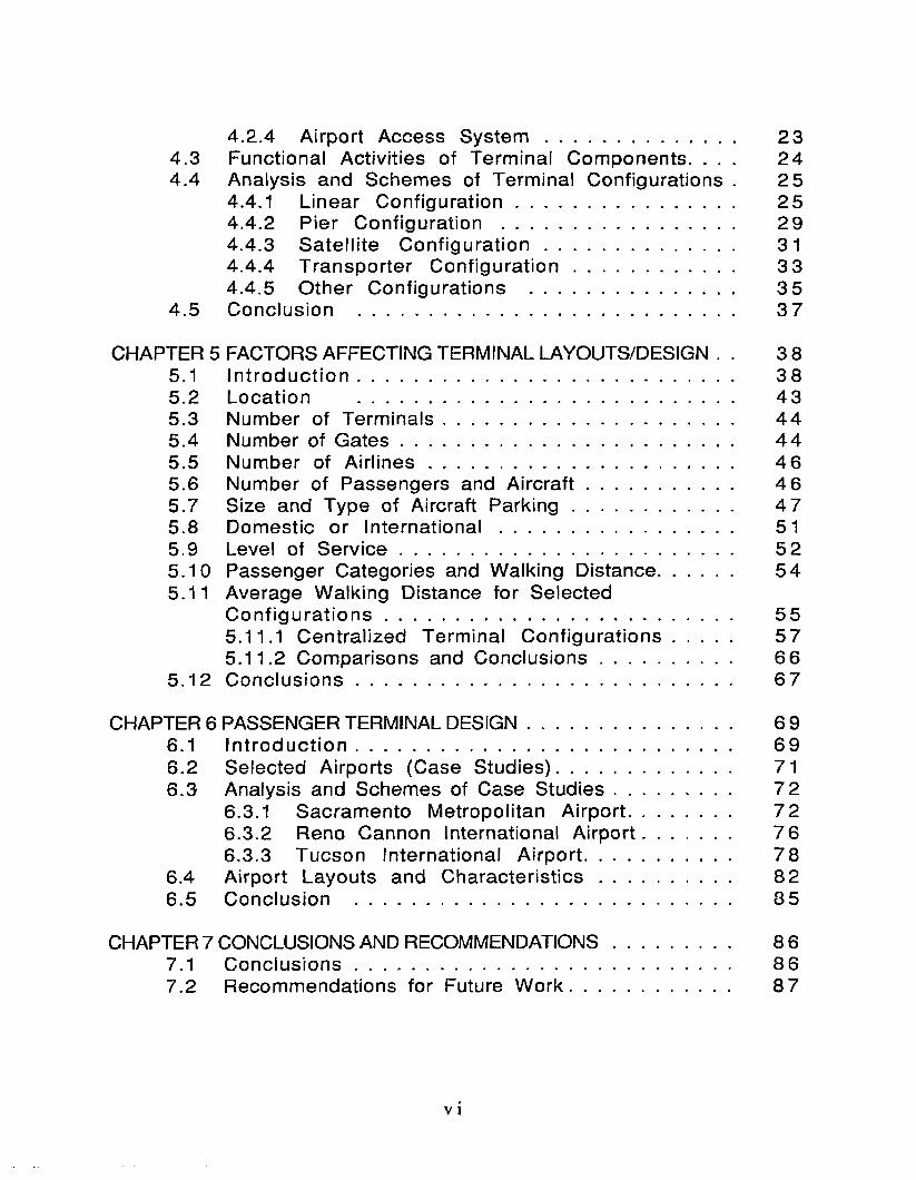
4.2.4 A irport Access S y s te m ....................................... 234.3 Functional Activ ities of Term inal Com ponents. . . . 244 .4 Analysis and Schemes of Term inal Configurations . 2 5
4.4.1 L inear C o n fig u ra tio n ............................................ 254.4.2 P ier C onfigura tion ............................................... 294.4.3 S a te llite C o n f ig u ra t io n ...................................... 314.4 .4 T ransporte r C o n f ig u ra t io n ................................ 3 34.4 .5 O ther C onfigurations ......................................... 3 5
4 .5 Conclusion ............................................................................ 3 7
CHAPTER 5 FACTORS AFFECTING TERMINAL LAYOUTS/DESIGN . . 3 85.1 In t ro d u c t io n ............................................................................ 385.2 Loca tion ............................................................................ 435.3 Number of T e rm in a ls ........................................................... 4 45.4 Number of G a te s ................................................................... 4 45.5 Number of A ir l in e s ............................................................. 4 65.6 Number of Passengers and A ir c ra f t ............................. 4 65.7 Size and Type of Aircraft P a rk in g ................................ 4 75.8 Dom estic or In te rn a t io n a l............................................... 515.9 Level of S e rv ic e ................................................................... 5 25.10 Passenger Categories and W alking D istance.............. 5 45.11 Average W alking Distance for Selected
C o n f ig u ra t io n s ....................................................................... 555.11.1 C entra lized Term inal C o n fig u ra tio n s 575.11.2 Comparisons and C o n c lu s io n s .......................... 66
5 .12 C o n c lu s io n s ............................................................................ 6 7
CHAPTER 6 PASSENGER TERMINAL DESIG N........................................ 6 96.1 In t ro d u c t io n ............................................................................ 696.2 Selected A irports (Case S tud ie s )................................... 716.3 Analysis and Schemes of Case S tu d ie s ....................... 7 2
6.3.1 Sacram ento M etropolitan A irp o rt.................... 726.3.2 Reno Cannon International A irp o r t................. 7 66.3.3 Tucson Internationa l A irp o rt............................. 78
6.4 A irport Layouts and C h a ra c te r is t ic s .......................... 826.5 C onclusion ............................................................................ 85
CHAPTER 7 CONCLUSIONS AND RECOMMENDATIONS........................ 8 67.1 C o n c lu s io n s ............................................................................ 8 67.2 Recommendations for Future W o rk ................................ 8 7
v i
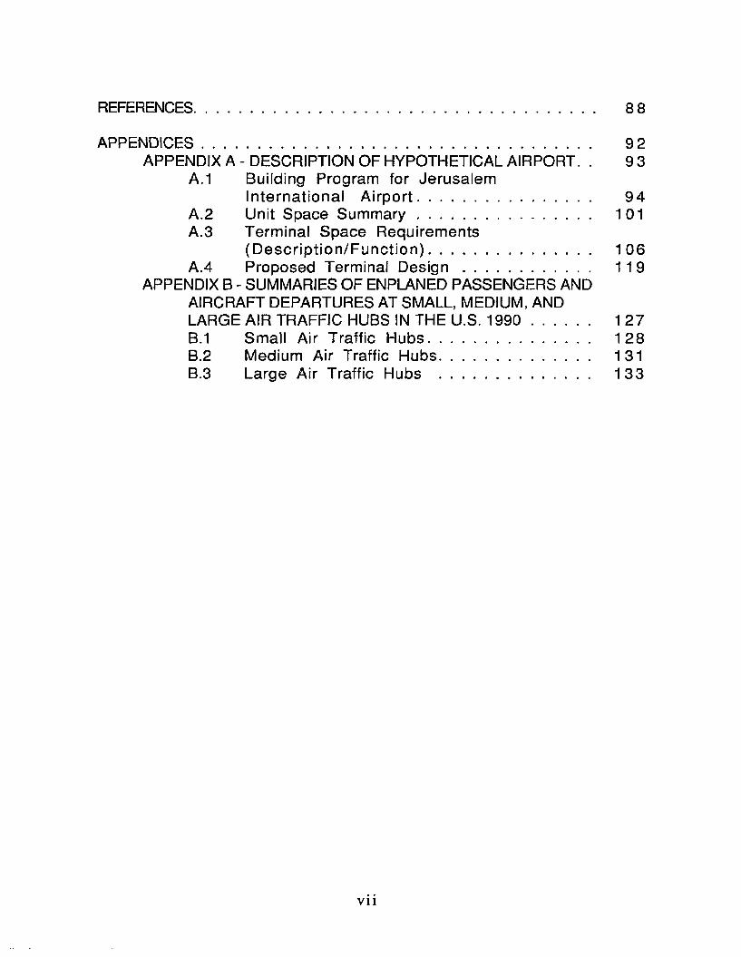
REFERENCES.................................................................................................... 8 8
APPENDICES 9 2APPENDIX A - DESCRIPTION OF HYPOTHETICAL AIRPORT. . 9 3
A.1 Building Program for JerusalemIn te rna tiona l A irp o r t ........................................... 94
A .2 Unit Space S u m m a ry ............................................ 101A.3 Terminal Space Requirements
(D e s c rip tio n /F u n c tio n )........................................ 106A.4 Proposed Terminal D e s ig n ................................. 119
APPENDIX B - SUMMARIES OF ENPLANED PASSENGERS ANDAIRCRAFT DEPARTURES AT SMALL, MEDIUM, AND LARGE AIR TRAFFIC HUBS IN THE U.S. 1990 .............. 1 27B.1 Small A ir Traffic H ubs......................................... 128B.2 Medium Air Traffic Hubs...................................... 131B.3 Large A ir Traffic Hubs ...................................... 133
vii

LIST OF FIGURES
Figure 2-1 Typical Forms of Connectors......................................... 13
Figure 4-1 Linear C o n fig u ra tio n ........................................................ 2 8
Figure 4-2 Pier C onfigura tion.............................................................. 3 0
Figure 4-3 S ate llite C o n f ig u ra t io n .................................................. 32
Figure 4-4 Transporter C o n fig u ra tio n ............................................ 34
Figure 4-5 Concept V a r ia t io n s .......................................................... 3 6
Figure 5-1 Gate Area/Apron for Nose-ln P a rk ing ........................ 4 9
Figure 5-2 A ircraft Parking Types..................... ................................ 50
Figure 5-3 S im p le -L in ea r-C on cou rse ............................................... 59
Figure 5-4 Basic-D ual-C oncourse .................................................. 61
Figure 5-5 T-Shaped Dual-Concourse............................................... 63
Figure 5-6 Rectangular-Dual C o nco u rse ......................................... 6 5
Figure 6-1 Sacramento Metro Airport (East T e rm in a l) 74
Figure 6-2 Expansion Schemes for Sacramento Metro
Airport (East Term inal).................................................... 7 5
Figure 6-3 Reno Cannon International A irp o rt.............................. 77
Figure 6-4 Expansion Schemes for Reno Cannon
Internationa l A irp o rt....................................................... 7 9
Figure 6-5 Tucson International A irport......................................... 8 0
Figure 6-6 Expansion Schemes for Tucson
In ternationa l A irport .................................................... 81
viii
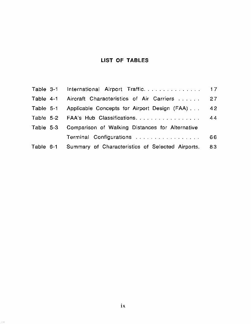
LIST OF TABLES
Table 3-1 International A irport T ra ffic .................. 17
Table 4-1 A ircraft Characteristics of A ir C a r r ie r s ....... 2 7
Table 5-1 Applicable Concepts for Airport Design (FAA) . . . 42
Table 5-2 FAA's Hub C lassifications........................ 44
Table 5-3 Comparison of Walking Distances for Alternative
Term inal C o n f ig u ra tio n s ...................... 66
Table 6-1 Summary of Characteristics of Selected Airports. 8 3
ix
ACKNOWLEDGMENTS
I would like to thank my co-chair and advisor, Dr. Shashi K.
Sathisan, for his valuable guidance, time, and tremendous support
during the early stages and throughout the development of this
thesis. His interest and knowledge in airside and landside
transportation systems contributed much to the com pletion of the
th e s is .
I would also like to thank Dr. J. Hugh Burgess for his efforts
and comments throughout the design development of this project. I
would like to extend my special thanks to Dr. Reginald R. Souleyrette
for his concern and appreciation to my work. Many thanks to Mr.
Richard M. Beckman for his helpful comments and suggestions.
I am grateful to Mr. George J. Rakers, manager at McCarran
International A irport, for sharing his knowledge in the operation and
functioning of international term inals. I also wish to thank Mr. C. W.
Fentress for his ideas, comments, and experience in international
a irport design.
I am particularly indebted to my special friend Pamela
Littleton, who has been very supportive throughout my architectural
studies and throughout my thesis work. I would like to extend my
special thanks to my best friend Jim Mark, for his final support
during completion of the drawings.
I would also like to thank all my good friends at UNLV for their
help in making this experience very meaningful.
Finally, I wish to acknowledge my family for their
encouragem ent.

1 INTRODUCTION
Airports serve a broad and complex range of needs related to
the movement of people and goods. Passenger and cargo shippers
gain access to national and international air transportation through
airports. A irlines and other operators of a ircraft use airport
facilities to serve passengers and shippers and to operate, maintain,
and store their aircraft. The community served by an airport may
depend on the airport for transportation, jobs, business
opportunities, and recreation (TRB 1987).
Although it is d ifficu lt to draw a precise line separating the
a irport from aviation, professionals define a irport in terms of
airside and landside. The Federal Aviation Adm inistration (FAA)
defines the airside as "the airfield and its components: runways,
taxiways, apron, and gate areas. The landside includes the terminal
buildings, access roads, parking areas, and services provided for
users of these facilities (USDOT 1976).
The passenger term inal building is the main interface linking
the airside and landside at an airport. The airport term inal must not
only accommodate numerous and diverse functions but must also be
responsive to constant change. Therefore, the passenger term inal
presents a complex task in planning and design, and errors can be
correspondingly costly (Odoni 1992).
The planning and design of terminal building is complicated
because of the multitude of factors that are involved. Three types
of major traffic entities need to be combined when dealing with the
landside/a irside planning and design: vehicles, passengers, and
a ircra ft (Hart 1985). Consequently, when build ing a new or
expanding an existing a irport
te rm ina l fa c ility it is c ritica l to provide e ffic ie n t and e ffec tive
design solutions. Hence, it is im portant to have a coherent
m ethodology to se lect appropria te term inal con figu ra tions before
developing a detailed design. The design approach should also
conclude a method to eva luate the efficiency and effectiveness of
the selected configuration. However, this thesis addresses only
e lem ents re lated to the a irpo rt passenger term inals.
This thesis exam ines the main elem ents in term inal building
design w ith respect to the ir function and operation. It investigates
the standard design of a lte rna tive term inal bu ild ing con figura tions
and the ir influence on passenger walking distances. The influence of
various factors on the term inal layout and size is also studied in
th is research effort. Finally, a hypothetical a irpo rt was designed
taking into account pertinent design factors, toge ther w ith an
analysis o f selected case studies.
The growth in air tra ffic over the past years has been steady
and rapid worldw ide. Increasing demand in term s of a ircra ft
operations, and passenger volum e have been identified as the major
in fluencing factors of a irport term inal planning (TRB 1987). The
term inal configuration and a ircra ft gate design have an influence on
the passenger walking distance, which is one of the prim e levels of
service to be considered. The size of term inal fac ilities are
governed by passenger demand and passenger mix which influence
the se lection of a term inal configuration.
1.1 Statement of Purpose
The purpose of this thesis is to study/evaluate factors
specifica lly walking d istance considerations in fluencing a irport
term inal design. Further, the project will include the development
of an appropriate design for an international passenger term inal
building for Jerusalem that is effective and effic ient for passenger
accommodation, and expansion adaptability consideration. The scope
of in terest has been lim ited to the term inal building facilities from
the entrance/exit at the landside to the gates. It does not cover
airport access and ground transportation facilities at the landside
or a irport runway and taxiway facilities at the airside.
The main objectives of this thesis are:
1. To investigate the main elements influencing term inal design
configuration with respect to the role of each element in
terms of its operation and function.
2. To investigate the plans of term inal building configurations
with consideration of the passenger walking distance, by
taking into account the various elements in term inal buildings
regarding the ir operational characteris tics, va riab ility of
tra ffic level, and types of passengers (arriving, departing and
tra n s fe rr in g ) .
3. To investigate and analyze the term inal configurations of
three medium airports in the U.S.A. based on their design
characteristics and number of gates, to obtain a desirable
te rm ina l con figura tion .
4. To develop a building program to design an efficient airport
term inal fo r Jerusalem.

To apply the results of this investigation to the design of
future Jerusalem Air Terminal.

2 LITERATURE REVIEW
2.1 Current Terminal Planning Techniques
In the literature on airport terminal, the areas of concern are
usually focused on the processing components of passengers and
baggage. Some of these components include airline ticket counters,
holding rooms, and baggage claim areas (Muller 1987). The common
process in planning an airport term inal building is normally initiated
by developing a building program to identify needed characteristics.
These characteristics are then dimensioned to fit in the appropriate
area based on its performance.
2 .2 Terminal Configurations and Characteristics
Airport configuration could be defined as the number and
orientation of runways and the location of the terminal area relative
to the runways. The number of runways depends on the volume of
traffic and the orientation depends on the direction of the wind and
sometimes on the size of the area available for airport development.
The terminal buildings serving passengers should be located to
provide easy and short access to the runways (Ashford and Wright
1992).
The airport term inal building, which contains all the systems
necessary to process passengers and baggage/cargo, is an
interchange facility between ground and air transportation. A
variety of geometries and mixed configurations are found among the
existing airport terminals around the world. They have usually been
categorized into four main groups according to the ir configuration
which differ in the method of linking the main term inal building
with the aircraft gates, and the degree of centralization for
passenger processing. The four configurations are commonly
referred to as pier, satellite, linear, and transporter. The
conventional diagram m atic circulation patterns are illustrated for
each, later in this chapter.
2.2.1 Evolution of Airport Terminals
The development of the world's airports over the last 60 years
reveals many attempts to plan and predict the needs of aviation,
commerce, and national pride (Blow, Brownring and Turner 1993).
There are three different generations in airport term inal
development. The first generation terminal (1930-50), was a simple
allowing a direct interchange between airport access modes and the
aircraft. Second generation airport terminals were built in the late
1950’s as a result of increases in air traffic and the demand for
more aircraft position and gates. These gates were attached to an
existing simple terminal, usually through concourses which also
increased the passenger walking distances. Third generation airport
term inals have recently developed as a result of the demand for
gates, which can’t be efficiently solved through the addition of more
concourses; and in many cases the use of mechanical moving devices
have been incorporated to alleviate increased walking distances that
have arisen. However, the four basic terminal configurations
mentioned above are the result of the growth process that began in
the early 1930's with the formation of airlines and scheduled flights
which has continued to the present.
2 .2 .2 Terminaf Concepts
As airport term inal concepts developed over the years, the
main objective of the design has been the safety and convenience of
the passengers. The physical and psychological characteristics of
the term inal should facilita te a convenient transition from an
automobile or public transportation through the term inal to the
a ircraft and vice versa. Therefore, basic term inal configurations
were developed around methods of passenger processing. Some of
the objectives to be considered in the development of a term inal
area plan are: passenger walking distances, parking, and ground
transportation systems. Many of the configurations have emerged
unsatisfactorily , particu larly when certa in values or individual
expression have taken precedence over function. It might be
d ifficu lt to create a term inal in which all the component systems
perform perfectly (Hart 1985). Some of the most critical systems
are those which deal with passenger walking distances, congestion,
and delays due to the increasing demand for air transportation. Many
of the solutions to problems of airport term inal public areas go hand
in hand with the solutions to the overall system. Overcrowding and
inconvenience in passenger areas occur when faults appear in the
tota l system.
2 .2 .3 Terminal Configurations With Respect To Walking
Distance
The literature on airport term inal configurations concentrates
on discussing the applicability of different term inal concepts (Hart
1985). An extensive research by many authors had identified that
term inal concept is a factor that affects the final performance of
the processing of passengers. It has a great influence on the amount
of walking distance a passenger has to walk to enplane and deplane,
its requirements of duplication of facilities, and on the structure of
services the airline have to provide to their passengers (Lemer
1992). Therefore the service quality at an airport term inal building
is influenced by the term inal physical characteristics.
Wirasinghe, Bandara, and Vandebona (1987) proposed a method
to determ ine the optimum geometries for equi-length pier-finger
type term inals that minimized the passenger walking distance
within the term inal. They identified the fraction of transferring
passengers and the number of gates as the influencing factors in
selecting the term inal geometry.
Baron (1969) proposed a method to evaluate passenger walking
distances for terminal buildings. The primary purpose of this
method was to evaluate terminal (arriving and departing) passenger
walking distances are to be computed using the actual number of
passengers on each flight and the distance based on the gate the
flight is assigned to instead of using static average walking
distances. The use of the proposed method was illustrated using an
example that compares an open apron, and finger-pier with
decentralized passenger handling, and a unit terminal design.

Further improvement of the proposed method was foreseen by
applying different weights for different passenger groups.
Braaksma (1977) offered a very interesting analysis of
walking distances. The emphasis was on the operational use of
existing facilities as opposed to the earlier efforts made in project
planning stages to produce an optimally designed terminal building.
His analysis showed
that walking distances can be reduced by the selection assignment
of flights to gate position. The results show that for terminal 2 at
Toronto International Airport walking distances were reduced as a
direct result of gate assignment policy.
Babic, Teodorovic, and Tosic (1984) proposed a method to
minimize walking distances by properly assigning aircraft to gates
every day in manner that takes into account passenger flows on the
particular day. This method is a practice showed that some of the
larger airlines adapt at major hubs.
Robuste (1991) analyzed and compared several centralized
airport configurations in terms of the average total walking
distance, with all transferring passengers being considered as hub
tra n s fe rs .
2 .2 .4 Interaction, Efficiency of Terminal Elements
There are certain interactions between the elements of the
term inal system, its land/ air environment, and between systems
within the terminal itself. The value of the basic terminal
configurations is determinable and may be defined through
comparisons of effects of these interactions. Each concept may be

evaluated within a particular situation, but, since the focus of this
thesis is to design a hypothetical terminal building considering
passenger walking distances, the most desirable configuration or
combination of two will be used for design application. However,
the degree of efficiency to a particular concept will depend to a
great extent upon the methodology used, the person evaluating it and
the way it is perceived.
2 .2 .5 Terminal Function
To facilitate the desired functions of an airport terminal
building linking different modes of transportation, a set of system
components is required. The configurations of these components
w ill thus greatly influence determine the term inal structure. The
systems include ground transportation, passenger processing,
transferring passengers, various services, and term inal management
controls. They are interrelated through their function and the
spaces they occupy. Space relationships within a typical terminal
building may be characterized in a matrix system. The spaces could
be classified in three groups: necessary, preferred, and non-related.
Based on their assigned values in the matrix, one can determine the
degree of importance of their relationship, and incorporate the same
in the building design.
2 .2 .6 Terminal Flexibility
The airport term inals created initially with space for
flexibility have been able to respond to growth and change best
(Blow, Brownrigg and Turner 1993). In any evaluation of basic

term inal configurations, one of the considerations which must be
emphasized is flexibility. This issue is usually considered by the
designer because of changes of aircraft characteristics such as size,
speed, maintenance, service requirements, and capacities.
Therefore, the term inal functional arrangement should be flexible
enough for handling passengers and ground-servicing, to achieve
minimum gate occupancy time and maximum airline operating
economy. For example, the terminal design of public spaces, baggage
claim, ticketing, service rooms, and corridors, must be able to adapt
to crowds of various sizes throughout the day and to meet increases
in these numbers over the years. At the curbs and in parking areas,
the airport must be able to meet changing demands in number and
size of automobiles and other types of ground transportation.
However, the technology of the terminal, its airside system and the
access system have slowed behind aircraft technology. Many of
these incompatibilities may be resolved through technological
changes; by introducing something new to the system or through
improved and more systematically flexible design procedures.
2 .2 .7 Basic Terminal Configurations
There are two basic concepts for the arrangement of the
term inal buildings: the centralized and unit. In a centralized
terminal, all passengers and baggage are processed in one building;
while in unit term inals, each airline (or several airlines combined)
may be located in a separate terminal building. These two design
concepts are often combined in various schemes. A single
centralized terminal building has many advantages and for most
cases is preferable over the unit terminal concept, because of its
compact operation, avoidance of transferring passengers and
baggage between buildings, and lower total cost for building
maintenance and operating. A unit terminal concept can be justified
only at very high activity airports.
A terminal building design can be categorized into four basic
configurations which are: the pier, satellite, linear, and transporter.
In addition, there are variations or combinations of these concepts
in term inal expressions which were originally composed of elements
drawn from these four basic terminal configurations. The connector
is the only element that distinguishes between the various concepts,
since it is different in each case. It is the proceeding element
between the terminal block and the apron gates. The four typical
forms of connectors used in airport design are: linear, pier,
underground, or transporter connector (see figure 2-1). Also, the
definition of the terminal configuration varies according to the
designer, depending on the depth of description involved.
The four configurations described herein were chosen for evaluation
because of the ir distinctive characteristics for passenger
processing as well as their differences in areas associated with
aircraft and ground support systems.

PLAN
\
T tM U I
1
1 '
i jI j
1
it iT f
V
CURB
TERMINAL
5353
BB
BB
APRON
PLAN
CURB
TERMINAL
c o n n ec to r"
7CONNECTOR
(TRANSPORTER)
K KCURB
TERMINAL
CONNECTOR
APRCN
Source: U.S.D.O.T., FA A, AC 150/5360-13, 1988
Figure 2-1 Typical Forms of Connectors

2 .2 .8 Conclusion
It should be realized that there are many other terminal
characteristics worthy of evaluation, and airport term inal designers
should not elim inate them while preparing a specific term inal
design. However, for the purpose of this thesis, the four basic
configuration (pier, satellite, Linear, and Transporter) and their
diagrams are further evaluated in chapter four to form the basis of
the proposed term inal design in this project.

3 RESEARCH METHODOLOGY
3.1 Process
Current terminal planning and design techniques are usually
approached with past experience consulting groups with usually
participation or inputs from airport management, the airlines, and
concessionaires. The designers and consultants are normally
engaged by the owner who may be a Federal, state, or municipal
government department, a statutory airport authority, or an
ind iv idual a irline
(Wilkes and Robert 1988).
Currently, there is no established method to evaluate the
impact caused by different planning alternatives or by different
management decisions. The current methodology is at most a
guidelines only, used and adjusted by understanding and experience
of small selected group of experts.
3 .2 Collection of Data
The design process of term inal facilities normally includes
compiling surveys, questionnaires, forecasts, evaluating existing
facilities, developing peak activity tables, and analyzing space
requirements for alternative designs. From this data collection the
designer can analyze alternative concepts and select the most
efficient and effective terminal layout. It is the role of the
Architect to analyze all the gathered information and put into a
design concept that services the overall system.
The general size and scope of the term inal facilities is
d irectly related to the amount and type of traffic that is expected to
flow through the term inal in a selected planning period. The
planning of a irport term inal facilities depends on the am ount of
tra ffic that flows through the term inal. The facilities are planned
on the basis of activ ity forecasts which include passenger
enplanements, passenger originations, and aircraft movements. The
term inal is then planned, sized, and designed to accommodate peak
passenger demands for a selected forecast period.
3 .3 Selection of Airport Configuration
The Methodology of this thesis was to evaluate factors
in fluencing a irpo rt term inal design con figura tion , spec ifica lly fo r
passenger average walking distance. The four s im ple/centralized
layouts considered to evaluate passenger average walking distance
were: S im ple-linear- concourse, basic dual concourse, T-shaped
dual-concourse, and rectangular-dual-concourse.
3 .4 Selection of Airports for Case Studies
Three selected case studies were briefly analyzed to provide
dimension guidelines, to enhance the proposed airport building
program, and to provide feasible characteristics for Jerusalem
future air term inal. The selection of case studies (Tucson
International A irport, Sacramento Metro Airport, and Reno Cannon
International A irport) was conducted because the ir s im ilar
passenger enplanements to the average enplanement of four
international airports adjacent to Jerusalem area (Israel, Jordan,
Syria, and Cyprus). The projected passenger enplanement was based
on this average and assumed to be one million passenger per year
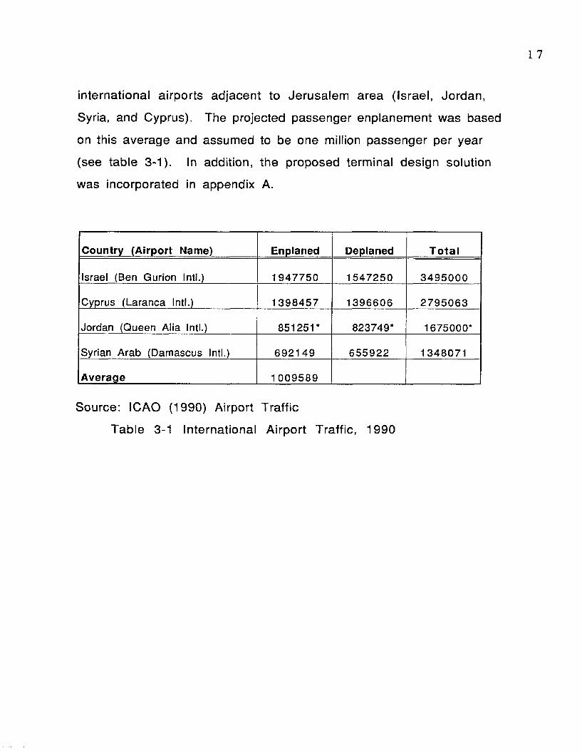
(see table 3-1). In addition, the proposed terminal design solution
was incorporated in appendix A.
Country (Airport Name) Enplaned Deplaned T o ta l
Israel (Ben Gurion Intl.) 1947750 1547250 3 4 9 5 0 0 0
Cyprus (Laranca Intl.) 1 39 8457 1396606 279 5 0 6 3
Jordan (Queen Alia Intl.) 851251* 823749* 1675000*
Syrian Arab (Damascus Intl.) 69 2 1 4 9 655922 1348071
Average 100 9589
Source: ICAO (1990) Airport Traffic
Table 3-1 International A irport Traffic, 1990
4 Airport Terminal Planning and Design
4.1 Introduction
The primary function of an airport term inal building is to
facilita te the movement and processing of passengers and their
baggage between the aircraft and ground transportation:
access/egress vehicles for originating and arriving passengers and
between a ircraft for transferring passengers. Normally, airport
terminal buildings are planned to handle some expected peak
passenger traffic at certain hours of the day. This chapter presents
a brief description of major airport components and their impact on
a irpo rt function.
Planning and designing an airport facility requires a
considerable amount of coordination and input involving a number of
airport users and other interested parties. These interested groups
include the a irport m anagement/operator, a irlines, Federal Aviation
Administration (FAA), local and regional public agencies. These
groups deal directly with each other on matters affecting airport
and airline operations. For example, the airport operators work
cooperatively with airlines and the FAA; airlines operate at the
airport under the terms of leases for terminal space and gates; the
FAA adm inisters programs to support airport planning and
developm ent of airport facilities and to ensure an effective and safe
national and international air transportation system. The
interaction among these groups influence airport operating and

development decisions. Therefore, it is necessary and important
that the architect/engineer develop and maintain a line of
communication with all these groups from the earliest stages of the
project to its final conclusion. They are the decision makers
responsible for the functional and operational design development.
Input must be solicited from these professionals and organizations
to present credible bases for identifying and making clear functional
choices of facilities design.
These professionals seek to create and predict adequate design
solutions to satisfy passenger and terminal needs of new or existing
terminals. They usually make recommendations based upon their
services, experience, and predictions. Yet, there is no generally
accepted definition of what is suitable terminal design. However,
the continuing growth in air passenger demand and the evolution of
aircraft technology make architects and engineers interested and
aware of airport terminal design, both in its performance and
characteristics (Lemer 1992).
4 .2 Major Airport Components and Their Function
For a term inal to achieve its primary function, the facilitation
of the transfer of passengers and baggage, the terminal building
must be composed of required components. These are: passenger
processing, baggage handling, and security, and are provided to
passengers whether arriving or departing. The characteristics of
passengers using the airport also determine the required components
of the terminal (e.g. customs and immigration are mandatory at a
terminal handling international passengers but not at a term inal
2 0
handling only domestic passengers).
In addition to the required components, term inal buildings
usually have a set of optional components that provide amenities for
passengers such as, restrooms, shops, restaurants, and telephones.
However, in order to accomplish this interchange the follow ing
major components are required: apron, connector, main term inal
building, and an airport access system (USDOT 1988).
4.2.1 Apron
The airport apron includes the area and facilities used for
a ircraft parking, support, and servicing operations. It also includes
the following sub-components: (USDOT 1988).
1. A ircraft gate parking positions: These are used for parking
aircraft to enplane and deplane passengers. Normally the
passenger boarding device is part of the gate position
(jetways). Size of this area is dependent on the aircraft type
for which it is designed.
2. A ircraft service areas: These are adjacent to the aircraft
parking position and are used by airline personnel/equipment
for perform ing the functions related to aircraft handling at the
gate. These areas are required to some extent at every airport,
although the requirements differ according to the station and
the airlines involved. A ircraft service areas can be
categorized based on the type of aircraft serviced and the
maintenance required.
3. T ax ilanes: These are provided to move aircraft between active
runways and the apron/parking positions.
4. Service/fire lanes: Designated for aircraft ground service
vehicles and fire equipment (FAA 150/5360-13).
4 .2 .2 Connector
The connector consists of the facilities which are normally
located between the aircraft gate position and main term inal
building. It normally contains the following elements:
1. .Concourse: A pathway for circulation between aircraft gate
parking positions and the main terminal building for enplaning
and deplaning passengers.
2. Departure Lounae: The waiting or holding area for passengers
prior to boarding an aircraft. These areas should have the
capability to accommodate passengers until a ircraft boarding
begins. In some instances it may be a mobile lounge used to
transport passengers to an aircraft parked away from the
te rm in a l.
3. Security inspection station: A facility to screen passengers,
visitors, carry-on baggage, and to control public access to the
departure lounge or other airport "sterile" areas.
4. A irline operational areas: A areas provided for flight
adm inistration, crews, personnel, offices, operations,
equipment and servicing activities related to aircraft arrivals
and departures. They are directly related to peak aircraft
movements as are the public areas of an airport terminal.
They are essential to the function of airport passenger
processing areas and should be provided according to the needs
of the particular airline.
2 2
5. Concessions: areas normally provided in both the connector
and the terminal components along the main traffic areas in
the terminal, particularly at busy airports with long
connectors. These include rest rooms, snack bars, beverage
lounges, news and gift shops, and other concessions for
passenger services. Concessions must be function effectively
according to passenger needs and must be located so that
passenger flow is not interrupted.
6. Building maintenance and utilities: Areas often included in the
connector and concourse components to provide terminal
building engineering, operations, and maintenance.
4.2 .3 Main Terminal Building
This component consist of the following elements:
1. Lobbies: Public areas provided for passenger circulation,
services, and passenger/visitor waiting.
2. A irline ticket counters/office areas: The counter area is the
primary location for passengers to complete ticket
transactions, baggage check-in, flight information,
administrative backup and at times baggage search.
3. Public circu la tion: Areas for general circulation which
include:stairways, escalators, elevators, and corridors.
4. Term inal services: Public and non-public facilities which
include: rest rooms, restaurants and concessions, food
preparation and storage areas, truck service docks, ground
transportation information and access, and m iscellaneous
storage.
5. Outbound baggage facility: A non-public area for sorting and
loading baggage into containers or carts for departing flights,
usually designated for specific airlines.
6. Intraline and. interline baggage fac ility : A non-public area for
processing baggage transferred from one flight to another.
7. Inbound baagaae facility: A non-public area for receiving
baggage from an arriving flight and public areas for baggage
pickup by arriving passengers.
8. Federal inspection service: A control point for processing
customs, immigration, and the quarantine of passengers
arriv ing on in ternational flights.
9. A irport adm inistration and services: Areas provided for
airport management, operations, and maintenance function.
10. P ub lic transporta tion : Consists of rental cars, taxis, buses,
limousines, or any other form of transportation hired on the
a irport grounds.
4 .2 .4 Airport Access System
This component is composed of ground elements which enable
entrance to, circulation w ithin, and exit from the a irport term inal
facility. They include the follow ing:
1. Curb: Platforms and curb areas which provide passengers and
visitors with vehicle loading and unloading areas adjacent to
the term inal. These usually consist of specially designated
areas for private autos, taxis, limousines,buses and other
courtesy vehicles.
2. Pedestrian walkways: Designated lanes, walkways, tunnels
and bridges for crossing airport roads to provide access
between auto parking areas and the terminal.
3. Auto parking: Areas providing short and long term parking for
passengers, visitors, employees, and car rental agencies.
4. Access roads: Vehicular roadways providing access to the
terminal curb, public employee parking, and to the community
roadway/highway system.
5. Service roads: Public and non-public roadways and fire lanes
providing access to various sub-elements of the terminal and
other airport facilities, such as air freight, fuel farms, postal
facility, and others.
4 .3 Functional Activities of Terminal Components
Activities of term inal components can be classified into three
functional areas: passenger processing and service areas; baggage
handling (including cargo); and aircraft servicing. An efficient
terminal design can provide a layout in which the various elements
are located in a sequence or pattern that creates natural passenger
progression. In addition, those activities and operations are
dependent on each other in terms of their functional system.
A good terminal building design could minimize passenger
walking distances, which is one of the concerns of this thesis. It
could also minimize servicing and processing times, congestion,
delay, and confusion. However, these activities/functions need not
have an individually defined area or even be applied to every
terminal design. For example, at low activity airport term inals, one

general space could satisfy multiple functions, such as a combined
lobby, ticket counter area, and waiting lounge.
4 .4 Analysis, schemes of terminal configurations
Figure 4-1 to 4-4 illustrate qualities of each of the term inal
configurations and their applications. It should be noted that the
dimensions used in illustrations are not intended to reflect
standards. Aircraft dimensioning has been set up to accommodate
B-747 size aircraft (Boeing, 1988 Table 4-1). For comparative
purposes, all dimensioning has been held constant with each basic
co n fig u ra tio n .
4.4.1 Linear Configuration
The development of the linear concept was an extension or
multiplication of the oldest and simplest concept. A single building
consists of a common waiting and ticketing area with exits leading
to the aircraft parking apron directly adjacent to it as shown in
Figure 4-1. This type of configuration is appropriate for airports
with low airline activity which usually have an apron providing
close-in parking for three to six commercial passenger aircraft.
This scheme is unlike other schemes in that it has the capabilities
for providing direct relationships between linear ramp frontage and
curb space and better integration of the term inal building with
access activity. This concept offers ease of access and relatively
short walking distances if passengers are delivered by the ground
access system to a point above the curb near the departure gates.

2 6
Expansion may be accomplished by linear extension of an
existing structure or by developing two or more term inal units with
connectors. In its simplest form, the linear concept involves the use
of several small
terminals arranged in a linear procession, each with a complete set
of systems necessary to the function of an isolated terminal. If
ticketing and baggage processing are provided for each terminal,
congestion may be kept to a minimum with passenger check-in and
waiting space directly adjacent to the aircraft served. A linear
concept may have various shapes, but all qualified linear schemes
have in common the direct integration of landside term inal
fac ilities with the airside.

Aircraft Type Engines Dimensions (ft) PassengerCapacityWing Span Length
B -7 4 7 -4 0 0 4 211 231.9 490
DC-10 3 165.3 182.2 380
B -7 0 7 -3 2 0 4 145.8 152.8 219
L-1011 Tristar 3 155.3 178.6 400
A-300 B4 2 147.1 175.8 345
B -7 2 7 -2 0 0 3 108 133.2 189
A 310-200 2 144 153.1 265
B -7 6 7 -2 0 0 2 156.3 159.2 255
B -7 5 7 -2 0 0 2 124.5 155.3 233
L 11-475 2 93.5 93.5 119
B -7 3 7 -2 0 0 2 94.8 101.8 132
Trident 3B 3 98 131.2 180
DC -9-50 2 93.3 125.6 139
DC-8 4 148 1 87 259
MD-80 2 1 08 136 172
MD-11 3 1 71 1 92 4 10
A -3 2 0 2 112 123 158
Source: Boeing 1988
Table 4-1 Aircraft Characteristics of Air Carriers

BI
3(
18 10'
3(
1! O'
25
Runway Centerline A .■ « - - 1
Outer Taxlway Centerline
Inner Taxiway Centerline
Maneuvering Taxiway Lanes
yA
y
Terminal Block
: [: 220* ; t*i Jr i s
Curb
20.' 220' an.* 220* an." 220- He 220' : 1- 14BQ?
Source: Blankenship, Edward G.
Figure 4 —1 Linear Configuration
2 9
4 .4 .2 Pier Configuration
The layout of the pier configuration introduced new methods of
passenger processing. This occurred as a result of changes in airline
procedures; from having a common passenger lounge (holding)
facility to a separate lounge facility for each flight. The pier
configuration provides interface with a ircraft along piers extending
from the main terminal area (Figure 4-2). Passengers in the pier
scheme can be processed and held in lounges immediately adjacent
to aircraft parked along the pier. Aircraft are usually arranged
around the axis of the pier in a parallel or perpendicular parked
relationship. Each pier has a row of aircraft gate positions on both
sides, with the passenger right-of-way or concourse running along
the axis of the pier serving as space circulation for enplaning and
deplaning passenger.
Piers were introduced in the first stage as additions to a
single main term inal to provide additional gates. The operational
advantages were rapidly realized and it became a very commonly
used concept in the
United States. There are many variations to the pier concept. In
some examples, the main terminal area is centralized and is
connected to the gates by single or multiple-linear piers, Y-shaped
piers, and T-shaped piers. Common central processing of passengers
(ticketing, baggage handling and security)-not for individual gates.
The pier concept, when applied on two levels, offered
possibilities for separating the systems with the various enplaning
and deplaning functions, by providing separate curbs, ticketing,
baggage claim, and circulation to aircraft in the concourses

3 0
6( I
3C0'
1870'151
220 '
4 =
220 '
a L
220 '
-----
8 3' —v-
Runway Centerline AA
5 ---------
Outer Taxiway Centerline
Inner Taxlway Centerline
T
A
A
1 7
A
V
A*
A
A*
Term inal B la c k
. 150'
150' . 250' :?o’ 250' . 150' •150'850'
1150'. r ■ r
Curb
S o u rc e i B lankenship, Eoiward G.
F ig u re 4 - 2 P ie r C o n f ig u ra t io n

themselves. Systems separation has been applied to linear,
satellite, and transporter schemes.
The flexib ility of the pier configuration is lim ited in terms of
passenger walking distances w ithout the use of mechanical moving
devices. This limit has been approached at major American airports
such as Atlanta and Chicago O’Hare. In some instances, they have a
walking distance more than a mile between the farthest gates. Also,
the lim itations of expansion in pier configurations extend to apron
areas and taxiways between piers; as a result of fixed piers cannot
move apart to allow for increased sizes of aircraft.
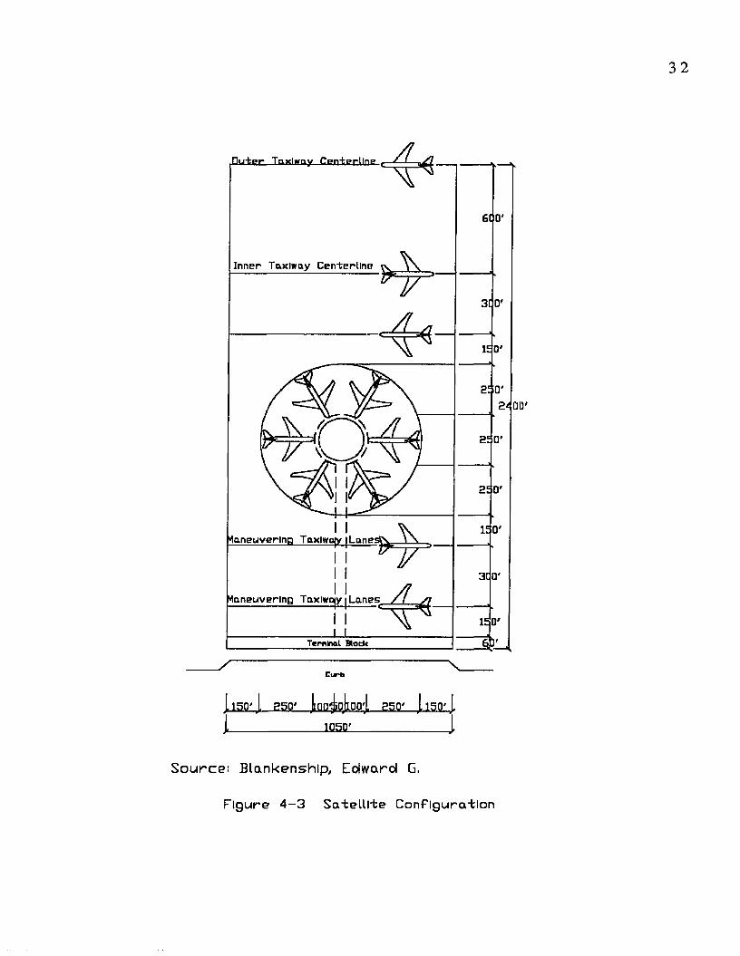
4 .4 .3 Satellite Configuration
The satellite configuration was introduced to improve airside
flexib ility through increased aircraft development and parking space
by placing connectors underground or above grade. The satellite
configuration consists of a building, surrounded by aircraft, which is
separated from the terminal (Figure 4-3). Usually, the primary
function of the central main term inal building is a link-up with
access modes such as ticketing, baggage claim, customs. One main
d is tinction between sate llite
and pier configuration is that some functions of the main terminal
could be taken care of in the satellite. The main advantage could be
the minimum walking distance for transfer passengers, when
transfers are w ithin the satellite.
A ircraft are normally parked in radial or parallel positions
around the satellite. This may be an advantage in sharing equipment
or service facilities, but it can also lim it expansion adaptabilities
□irtgr Taxlwny CenteKUnE:
Inner Taxlway Cen-terllne
SEI
"laneuverlnn Taxlwafy
^nneuverlns Taxlxojy Lanes
Tem lna l Slack
1 150*1 -2 50'. lonjjo jm oj 25Q' 1150*1
_______________1050!_______________ ..
Source: Blankenship, Edward G,
F ig u re 4 - 3 S a t e l l i t e C o n fig u ra tio n
both for interior building functions and for aircraft parking space
requirements. The satellite can have common or separate departure
lounges. Since enplaning and deplaning are accomplished from a
common area, mechanical moving
devices may be used to transport passengers and baggage between
the terminal and satellite. With these moving devices, walking
distances are kept to a minimum.
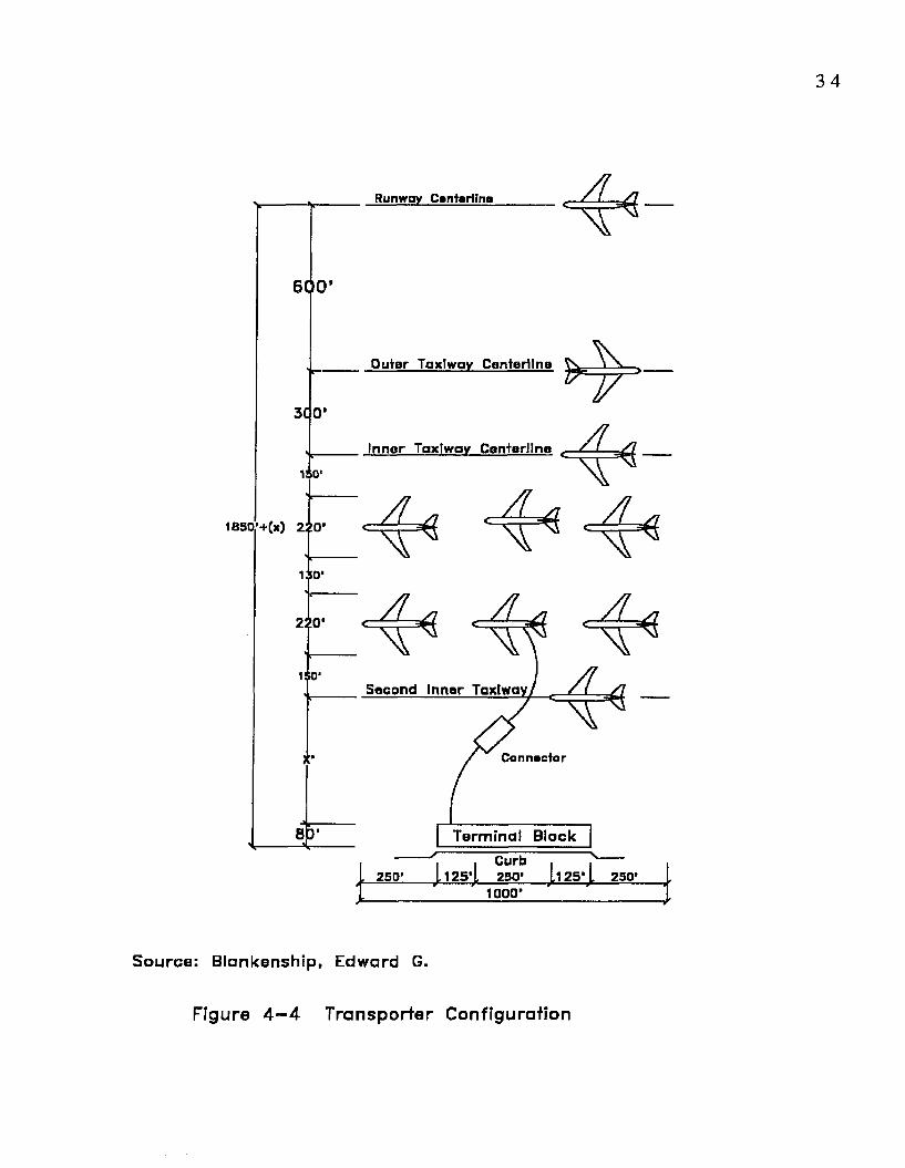
4 .4 .4 Transporter Configuration
The transporter or mobile lounge concept is sim ilar to the
connector scheme in that the piers and departure lounges have been
removed and replaced by mobile lounges or buses for enplaning and
deplaning passengers (Figure 4-4). A ircraft and aircraft servicing
functions are remotely located from the building. The
characteristics of the transporter concept include flexib ility in
providing additional a ircraft parking positions w ithout fixed
facilities to accommodate increases due to seasonal traffic
demands, schedules, or aircraft size.
From the airside there are apparent advantages. Parking the
a ircraft away from the main term inal allows for tax i-in /tax i-out
operations under its own power which elim inate expensive, time-
consuming aircraft towing operations, as well as congestion delays
due to clustered aircraft
servicing activities in terminal area. Moreover, the use of mobile
lounges helps reduce passenger walking distances when aircraft are
parked away from the terminal. Increases in passenger volumes may
be taken care of through additional mobile lounges or other
Runway Centerilno
600
Outer Taxlway Centerline
Inner Taxlway Centerline
150’
130 '
220 ’
Second Inner Taxlway
Connector
Terminal BlockCurb250 '125' .125*. 250 ’ 250 *
1000 '
Source: Blankenship, Edward G.
Figure 4 —4 Transporter Configuration
transporters, which are less costly initially and consume less space
than additions to a conventional building.
This concept offers a high degree of flexibility in both
operation and expansion. However, the length of time required
between departure of the lounge from the terminal and departure of
the aircraft, is greater than the time usually required for a late-
arriving passenger to get from the
enplaning curb down to a conventional connector to a departing
a irc ra ft .
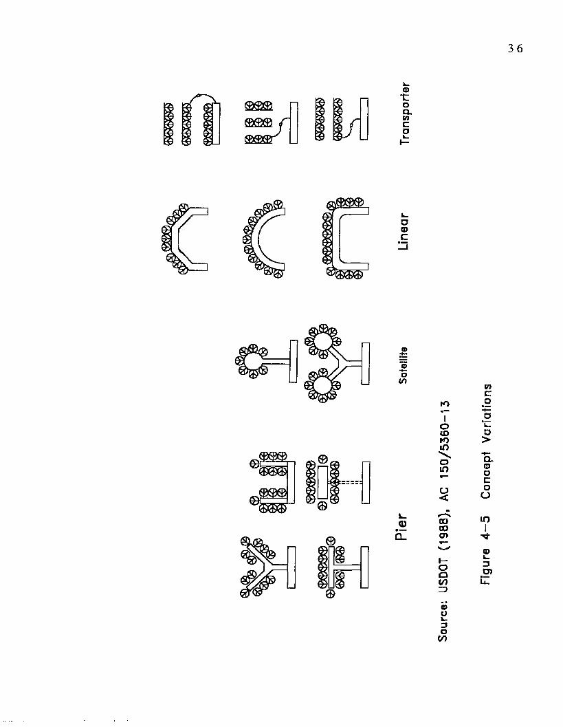
4 .4 .5 Other Configurations
In addition to the four basic terminal configurations there
have been proposals of combined concepts, which appear to extend in
different directions from accepted patterns of passenger and
service system (Figure 4-5). These combinations are a result of
changes in conditions experienced after the initial conception of the
airport. The purpose of such systems would be to help accommodate
changes in traffic demand or characteristics. These include growth
of aircraft schedules, air traffic demands that far exceed terminal
capacity, aircraft size or new mix of aircraft types servicing the
airport. In the same way, physical limitations of the site may cause
a pure conceptual form to be modified by additions or combinations
of other concepts.
3 6
3 7
4 .5 Conclusion
Airport passenger term inals are major public facilities. An
airport term inal encompasses various activities which have varied
and often conflicting requirements. They are interdependent with
each other, so that a single activity may limit the function of the
entire complex. In the airport design process analysis of one
activity w ithout regard to the effect on other activities will not
provide adequate solutions. Unsuitable term inal design facilities
can result in congestion and confusion. In the past, airport master
plans were developed on the bases of local aviation needs. In recent
times, these have been integrated into an airport system plan which
is influenced to a great extent by the local community that operates
the facility and is served by the airport. It serves not only the needs
at a specific airport site, but also the overall needs of the system of
airports which serve an area, state, region, or country.
5 FACTORS AFFECTING TERMINAL LAYOUTS/DESIGN
5.1 Introduction
The literature of airport term inal configurations concentrates
on discussing the applicability of different term inal layouts (Hart
1985). Prior to initiating an airport terminal layout design, a
building program needs to be developed (this will be discussed in
chapter seven of this thesis). After the building program and a
choice of apron terminal concept have been decided, the two critical
design concepts that affect the terminal layout are the degree of
centralization of processing passengers, and the choice of number of
building levels to be used.
Centralization usually implies that most enplaning and
deplaning passenger processing functions, such as ticketing (check
in), baggage claim, and other passenger processing areas, related to
aircraft gate positions regardless of their locations, are in a
centralized area which may be on one or two levels. In the
centralized terminal, the only decentralized functional areas are the
departure gate lounges (holding rooms). The satellite, pier, and
transporter layouts adapt themselves to centralized processing. On
the other hand, decentralization in its strictest form means that
passenger processing areas and baggage handling functions are
provided to handle a selected group of departing and arriving
passengers at almost every aircraft gate or for clusters of gates.
This type of terminal may consist of several term inal blocks
3 9
depending on the degree of centralization, and can be achieved in the
linear concept where aircraft are placed in a single line at the
te rm in a l.
There are advantages and disadvantages associated with each
of the two concepts. The advantage of a decentralized concept in its
precise form is that it offers the opportunity to reduce walking
distances within the terminal. Passenger walking distances must be
within generally accepted standards: less than 1000 feet (Hart
1985) between points of term inal entry and aircraft gate, or
between gates for transfer passengers. Theoretically, the enplaning
passenger can enter the building from the curb opposite to the
dedicated aircraft gate, and would have to walk through the depth of
the building without any digression. Similarly, the deplaning
passenger would have reduced walking distances between gate,
baggage claim, and the curb if dedicated bag claim areas were
provided to a limited number of gates.
There is also greater control of the passenger by the airline,
because the passenger does not need to travel long distances from
check-in to the aircraft gate. However, these advantages would be
lost if the transfer passenger was connecting from one airline to
another who might then be required to travel a significant distance
along a linear terminal. Some studies have shown that these
distances can be uncomfortably long within large decentralized
terminals such as in Toronto at the Pearson Terminal 2. Passenger
convenience would also be reduced if the passenger had parked his or
her automobile in the closest lot to the originating gate and were to
return at a different gate on a different airline, which would require

a long walking distance back to the vehicle. Decentralization
appears to be justified when aircraft gates can consistently be
dedicated to the same destination and aircraft when they are
arriving and departing at the same gates during the hours of the day.
Decentralization of more than eight gates will have problems in
directing arriving and departing passengers (Hart 1985). Therefore,
the centralization of major passenger and baggage handling
functions means better utilization of staff and ground handling
equipment, fewer concession locations, and less overall building
space. Subsequently, centralization means lower operating costs,
lower investments, and better service for passengers. For the
purpose of this thesis, the centralized term inal building concept
will be adopted primarily because of its distinct advantages
The second critical factor that affect the terminal layout
design is the number of building levels to be used. Normally,
terminal buildings have been designed to provide one level, one-and
a-half levels, or two levels of passenger processing. The one-level
concept is generally used in smaller terminals, processing up to 1
million annual passengers. The one-and-a-half level concept is
often an expansion from what was previously a one-level concept, to
enhance passenger convenience and safety. As in the one-level
concept, enplaning and deplaning passenger processing (with the
exception of security, which is normally carried out on the upper
level), curbs, and baggage systems are located at grade. The two-
level concept is used in larger terminals handling more than 1.5-2
million annual passengers. Typically, in the the two-level concept,
the departure level is on the upper floor and arrivals are at the apron

level. One of the principal advantages of the two-level concept is
that it lends itself to the adoption of the two-level roadway which
separates arrival and departure vehicle flows at the curb which
would create the opportunity to provide efficient arrival and
departure curb length. Since the objective of this thesis is to design
an international air terminal, only the two level concepts will be
considered because of their general use in international airports.
Based on guidelines provided by the Federal Aviation
Adm inistration (FAA) the applicability of various concepts
previously described, relating to the number of annual enplanements
to be handled and the proportion of transferring passengers are
summarized in Table 5-1. This will be used in chapter six to
categorize the three selected case studies and their characteristics.
To arrive at an optimum term inal configuration, it is
necessary to develop an understanding of the different factors
affecting term inal layout and the various passenger categories,
their distribution and the walking patterns within the terminal. The
most appropriate terminal design configuration for the given
conditions can be developed based on the knowledge of optimal
factors for the selected term inal layout and their influences
between geometries. However, this thesis will consider only some
of the main factors to be discussed further, which may significantly
impact the planning and design of an airport terminal configuration.

Tabl
e 5-1
Ap
plic
able
Co
ncep
ts
for
Airp
ort
Desig
n (F
AA)
4 2
Boa
rdin
g
Air
craf
tLe
vel
X X X X X X
Apr
onLe
vel
X X X X X X X X X
Con
nect
or
Mul
tiLe
vel
X X X X X X
Sin
gle
Leve
l
X X X X X X X X
Term
inal Mul
tiLe
vel
X X X X
Sin
gle
Leve
l
X X X X X X
Curb
Mul
tiLe
vel
X X X X
Sing
leLe
vel
X X X X X X X X X X
Conc
epts
Ap
plic
able
Tra
nsp
ort
er
X X
Sat
ellit
e
X X X X X X
Pie
r
X X X X X X X
Line
ar
X X X X X X
Airp
ort
Size
by
Enpl
aned
P
ax./Y
ear
Feed
er
unde
r 25
,000
Seco
ndar
y 25
,000
to
75
,000
75,0
00
to 20
0,00
0
200,
000
to 50
0,00
0
Prim
ary
over
75%
Pa
x.
O/D
50
0,00
0 to
1,00
0,00
0
Ove
r 25%
Pa
x.
Tran
sfer
s 50
0,00
0 to
1,00
0,00
0
Over
75%
Pa
x. O
/D
1,00
0,00
0 to
3,00
0,00
0i O
ver
25%
Pax.
Tr
ansf
ers
1,00
0,00
0 to
3,00
0,00
0
Over
25%
Pa
x. O
/D ov
er
3,00
0,00
0
Ove
r 25%
Pa
x.
Tran
sfer
s ov
er
3,00
0,00
0
Sour
ce:
U.S.
D.O
.T.,
FAA,
"P
lanni
ng
and
Desig
n Gu
idel
ines
for
Ai
rpor
t Te
rmin
al
Faci
litie
s",
AC
150/
5360
-13,
19
88
4 3
5 .2 Location
The location of an airport has an influence in determining its
size and terminal layout. The population and per capita income of a
particular area and their growth potential; geographic location and
distance from other airports with sim ilar or larger service areas;
obvious influences such as physical size and topography (terrain);
concentration of commercial activity that involves a relatively high
demand for air transportation; and major vacation/recreation areas
are all some of the significant factors of the airport term inal layout
design. A related but not essential factor in determining terminal
layout is that of the attitude of the community served by the airport.
The degree to which the construction or expansion takes place and
the size, spaciousness, architectural treatment, and overall
appearance will, to one degree or another, mirror the desires of the
community (TRB 1987).
One form of reference often used to describe an airports
service is the Air Traffic Hub Structure developed by the Federal
Aviation Administration (FAA) to measure the concentration of civil
air traffic. Individual communities fall into four hub classifications
as determined by each community’s percentage of the total U.S.
enplaned domestic revenue passengers carried. This is presented in
Table 5-2.

4 4
Hub sizePercent of total enplaned
passengers 1990 enplanem ents
Large (L) 1.0 percent or more 4,385,440 or more
Medium (M) 0.25 to 0.9999 1,096,360 to 4,385,440
Small (S) 0.05 to 0.249 219,272 to 1,096,360
Nonhub (N) Less than 0.05 Less than 219,272
Source: U.S.D.O.T. (1990), A irport Activity Statistics
Table 5-2 FAA's Hub Classification
5 .3 Number of Terminals
The number of term inals at an airport is an essential factor in
determ ining the terminal configuration. Designing for more than one
term inal requires additional awareness because each segment of a
terminal concourse relates directly to an area of the apron. Joining
two or more terminals must be done so that aircraft flows or access
modes do not interfere. Moreover, aircraft parking positions and
consideration of their maneuvering capability between term inals are
also essential in the design development with respect to space
requirements for taxi-in and taxi-out. Selecting the number of
term inals will also be affected by the number of gates desired, and
the number of airlines expected to use the airport.
5 .4 Number of Gates
The term gate is used here for an aircraft parking layout on the
apron. The number of gates at an airport is one of the main design

and operation factors at the interface of airside and landside
influencing both the term inal building and the term inal building
layout. These elements need to be considered during the planning
process.
The number of gates required depends on the number of
aircraft to be handled during the design hour, and on the amount of
time each aircraft occupies a gate (Horonjeff and Mckelvey, 1983).
Steps to be followed in calculating the required number of gates are:
1. Identify the types of aircraft to be accommodated and the
percentage of each type in the total mix.
2. Identify the gate-occupancy time for each type.
3. Computed average gate-occupancy time.
4. Determine the total hourly design volume and the percentages
of aircraft which are arrivals and departures.
5. Compute the hourly design volume of arrivals and departures
by the total hourly departures by the hourly design volume.
A very simple formula for the required number of gates is
G =V IU
Where:
V = design volume for arrivals or departures (in aircraft per
hour)
T = average gate-occupancy time during that period (in hours)
U = gate utilization factor (varies between 0.5 and 0.8).
This formula is valid under the assumption that there is a one-
to-one com patibility relation between aircraft type, flight type, and
gate position. For example, each and every aircraft independent of
4 6
type could and should use any of the existing gates. Horonjeff offers
a method to compute the total number of gates when there is more
than one type of gate and more than one type of aircraft. When data
are available, it would be preferable to compute gate requirements
separately for different types of aircraft, keeping in mind that
smaller aircraft use smaller stands but could also use stands meant
fo r larger aircraft.
5 .5 Number of Airlines
Another determ ining factor which affects term inal layout is
the number of airlines serving the airport. The number of aircraft
parking positions required by individual airlines during their peak
period is a factor that affects terminal layout. It is possible that
the peak period experienced by an airline and the airport will not
necessarily coincide-this is even more likely when multiple airlines
serve an airport. The number of gates required will also depend on
whether gates are shared between airlines. Other factors affecting
gate requirements include requests by airlines for preferential
parking positions.
5 .6 Number of Passengers and Aircraft
Two other key factors that affect airport term inal layout
design are the number of passengers (enplaned and deplaned) and
aircraft used. Similar to peaks in the number of scheduled aircraft
departures occurring during the day, passenger volumes may also
peak at certain hours of day. These are closely related and will
produce a high hourly demand in relation to annual traffic; a uniform
dispersion of passenger volumes over a day will lead to a lower
ratio of the hourly volume to the annual passenger volume. It has
been common for terminal design criteria to be related to the
number of passengers to be handled during the peak hour of
scheduled use. Additionally, it is to be recognized that seasonal
variations occur in daily and hourly passenger volumes. The
passenger volumes during absolute peak periods of a year could be
significantly higher than the average of the peak hourly passenger
volumes over the year.
This means that in the periods in the year when demand is greatest,
the facilities w ill not match the requirement, but may be adequate
to ensure reasonable standards and economy. In addition to the two
mentioned key factors, the average number of passengers per
aircraft is to be considered in terminal design. The average number
of passengers per aircraft would be specifically necessary to
determ ine gate waiting/holding areas, baggage reclaim units and any
other part of the term inal.
5 .7 Size and Type of Aircraft Parking
The size/type of aircraft which is to be accommodated and the
type of parking used, i.e, nose-in, parallel, or angled parking are two
main factors to determine the size of a gate (the apron area), which
ultimately affect the term inal layout design. The size of the
aircraft determ ines the space required for parking as well as for
maneuvering. The type of aircraft parking used at the gates affects
the gate size since the area required to maneuver into and out of a
gate varies depending on the way the aircraft is parked.

4 8
The a ircra ft m anufacturers and other professional
organizations association have provided guidelines for various
dim ensions required for d iffe rent types of a ircra ft and various
parking conditions. These dim ensions are suffic ient for prelim inary
planning between centers of gates and for sizing the apron gate area.
The dimensions depend on the type of aircraft to be used. The
typical dim ensions for the case where a ircraft enter a gate under
the ir own power and are pushed out by a tractor are shown in Figure
5-1. This figure also shows the changes in dimensions required for
d iffe re n t a irc ra ft types.
A ircra ft parking type refers to the a ircra ft positioned w ith
respect to the term inal building and the a ircraft m aneuvering (in and
out of parking positions). A ircraft parking type is an im portant
fac to r because the size of d iffe ren t a ircra ft require d iffe ren t
parking types, and consequently the apron-gate area and the term inal
layout in general. A ircraft can be positioned at various angles with
respect to the term inal building layout and can maneuver in and out
of parking positions either under the ir own power or with the aid of
towing equipm ent. Further, the a ircraft parking types which have
been commonly used at various airports and should be evaluated in
any airport planning study include: nose in, angled nose in, angled
nose out, and parallel (Figure 5-2).
There are advantages and disadvantages for each of the
aircraft parking configurations and no one can be considered ideal.
For any planning situation all the advantages and disadvantages of
the different system s have to be evaluated, taking into
consideration the preference of the airline that will be using the
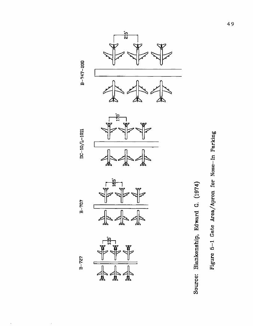
4 9
o0CMI
IV1
PQ
in*vr
CM
W W W
o▼H
J,No
oo
p-oI
PQ
CMIVI
PQ
w2^
Ah <A0
in
W ww
JiL Jok
, 'INOJ
C5TJFh
xJH
,3OPaCDXp5cd
r—H
m
CDOF*3o
U1
00c• H
XF-.d
Ph
aimo
Fho
p?oFh
< !
idCD
CD-+Jcd
U
LOCDFh
300
»rH

5 0
1=10)F-409Ph
.a0)co
'SF
T
UO"4PP
COCO05
uopHm
j>o
Mo
X3
75(0
«
CD•r— i
aohO
f f i
0)o£ho
cn
Figu
re
5-2
Air
craf
t P
arki
ng
Type
s
5 1
gates. In this thesis, however, the most suitable aircraft parking
configuration will be used based on the site characteristics
proposed in chapter five. Generally, the trend in planning and design
of airports has been normally toward nose in parking because of the
savings in area and the reduction of noise and je t blast to the
term inal. The characteristics of access and service equipment, such
as jetways, will be affected by the type of parking.
5 .8 Domestic or International
Airports with in ternational flights may have other
characteristics which influence term inal planning and layout design.
One of the characteristics is a tendency toward higher a ircraft
activity peaks because of the heavy dependence on schedules related
to time zone crossing from one city to another. Another
characteristic is the type of facilities required, depending on the
category of tra ffic handled at the term inal, whether domestic,
international, or com binations of the two. Also, the relatively long
ground service times (2 to 3 hours for turnarounds, 1 hour for
through flights) required for long distance aircraft serving long
international routes. The additional space requirements for federal
inspection service fac ilities required for in ternational fligh ts and
the extent of these facilities will also affect the term inal planning
and layout design. In some terminals outside the United States,
there may be specific requirements to separate and secure
passenger flows by sector, not only on the deplaning sequence but
also on the enplaning sequence. Furthermore, various functions that
require term inal facilities may be located at d iffe rent term inals in
5 2
various countries for enplaning and deplaning. Example of sucht
facilities include: security check, departure lounges, immigration
check, baggage claim, etc.
5.9 Level of Service and Comfort
Another important factor that affects term inal layout design
is the level of service to be provided to the users. The three
principal users of a passenger terminal building are the passengers,
airlines, and the airport operator.. However, the focus of this thesis
is limited to the passengers. Also, the needs of the passengers
should be given priority over other users in the planning and design
of passenger terminal buildings.
Martel, N. and Seneviratne, P.N. (1990) conducted a personal
interview survey of departing passengers to determine factors
influencing the quality of service in passenger terminal buildings.
They suggest that availability of space is not the most significant
factor influencing quality of service from the passengers point of
view, and thus it may not be the ideal parameter to use in a quality
of service analysis.
Regardless of the configuration, a passenger terminal building
contains three basic elements:
1). The processing elements (ticketing, check in, baggage drop,
security, immigration, customs, and baggage claim.
2. The holding elements (departure concourse, departure lounge,
gate lounge, transit lounge, and arrival concourse).
3. The circulating elements (ground access/egress, drop-off,
pick-up, corridors, and airside interface).
Quality of service is defined as the level of comfort and
convenience of the facilities and services that is essential to
process passengers in a terminal building. The importance of each
factor is evaluated according to the manner in which it is perceived
by different categories of passengers. However, the survey results
showed that the factors influencing quality of service differ for
various elements of the passenger terminal building. For instance,
53 percent of the respondents believed that the information is the
most important factor within the circulation elements. Similarly,
for the waiting areas the most important factor was the availability
of seats and for the processing elements, it was the waiting time.
Thus, the optimal set of evaluation factors for a particular facility
can only be determined by interviewing passengers (Martel, N. 1990)
Muller (1987) identified that the tools currently available for
airport terminal planning and design techniques do not account in
any aspect to the passengers needs. The research was conducted
based on three questions: 1. How do passengers perceive the quality
of the service? 2. What are the factors that passengers consider?
3. How important are these factors? Although some studies dealing
with these issues were identified, the above questions were still
unanswered. However, the approved method to deal with these
questions was the determination of a mechanism of transformation
of qualitative discrete data into quantitative continuum data. Then,
the behavior theory was useful in providing the required theoretical
support for the transformation of qualitative data into quantitative
data. A modelling framework was used to examine passenger quality
perception for different terminal operation situations. As a result,

5 4
the framework represented a step forward in the process of
passenger quality perception, the importance of term inal facilities
to the passenger perception, and it proved capable of estimating the
passenger perceived benefits as measured in dollars.
5 .10 Passenger Categories and Walking Distance
The passengers using an airport terminal building can be
categorized into two major groups: arriving/departing passengers
and transferring passengers. Arriving passengers are those
passengers arriving at the terminal by aircraft. They usually walk
from the arrival gate to ground transportation facilities, and when
necessary they walk through baggage claim area. Departing
passengers are those passengers coming to the terminal generally by
way of ground transportation. They walk from ground transportation
facilities to the departure gate through security checks and when
necessary check-in counters. Transferring passengers are those
passengers who transfer from one aircraft to another, usually
without leaving the terminal. They can be divided into two groups
depending on whether they have to walk to the terminal block for
processing or not.
Passenger walking distance is one of the major considerations
in the planning and design of airport terminals, and an important
measure of level of service provided to the passengers. Other
factors that need to be considered when a terminal configuration is
being chosen include available land area, construction cost, baggage
handling system, aircraft taxing time, landside access, and security
requirements (Hart 1985).

5 5
The next section focuses on comparing different geom etries
that minimize average walking distance for passengers to serve the
initial objectives and to provide general guidelines for term inal
building design. Therefore, the idealized geometries and analysis
presented in the following section are only general guidelines for
the proposed term inal design in this thesis (see Appendix A).
5.11 Average Walking Distance for Selected
Configurations
In this thesis, passenger average walking distance is
considered to be the principal factor to develop a desirable term inal
configuration. To facilitate the comparison of d ifferent layouts only
simple centralized term inal configurations are examined since many
of the existing small/medium sized airports belong to this category.
It is assumed that the available land is relatively flat, homogeneous,
roadway connections to the terminal block exist for access to the
airport, and a taxiway exists to connect the gates to the runways.
The four selected centralized term inal configurations are:
simple linear-concourse, basic dual-concourse, T-shaped dua l
concourse and rectangular dual-concourse (Figures 5-3 to 5-6). The
geometry of these four term inals are distinguished from linear
term inals which are decentralized. They all have a central block
that groups ticketing and baggage handling spaces in one area, and
aircraft gates are located along the concourses connected to the
central block for all of the four cases.
The average walking distance in an air term inal does not
include, for example individual passenger movement to retail
5 6
centers and convenience facilities. Walking distance between the
parking area and the terminal is not considered because it is
assumed to be the same for all of the four configurations. Further,
the effects of moving walkways on reducing the average passenger
walking distance are not considered and equal to zero.
Assuming that the four selected terminal configurations have
identical number of gates (G) able to accommodate any aircraft type
and evenly spaced at distance (d). The total linear frontage required
to accommodate "G" gates, spaced "d" apart will be constant
irrespective of the terminal configuration. This frontage is assumed
to be 2L. Further assume that a random passenger has an equal
chance of boarding an aircraft at any of the gates. All the layouts
include a rectangular terminal block (dimensions being 2 axb) with a
unique passenger entrance-exit gate in the middle. The width of a
concourse is identical in all of the four cases. It is also assumed
that the average walking distance of a passenger departing from a
particular gate and a passenger arriving at the same gate will walk
the same distance (Wo) on the average. Although departing
passengers might pass a ticket counter and arriving passengers pass
by the baggage claim devices, this is only an approximation because
neither of these facilities can be located exactly in the middle of
terminal block. For this type of passengers (i.e., originating or
destination), the calculated average distance is the distance from
the entrance-exit gate of the terminal block to all possible aircraft
gates of the terminal.
For a passenger arriving at a particular gate and transferring
to another gate (transferring passengers.), the average distance
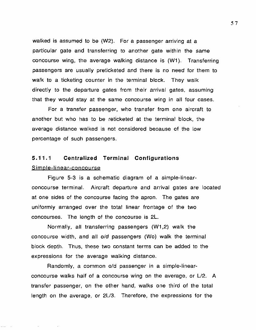
5 7
walked is assumed to be (W2). For a passenger arriving at a
particular gate and transferring to another gate within the same
concourse wing, the average walking distance is (W1). Transferring
passengers are usually preticketed and there is no need for them to
walk to a ticketing counter in the terminal block. They walk
directly to the departure gates from their arrival gates, assuming
that they would stay at the same concourse wing in all four cases.
For a transfer passenger, who transfer from one aircraft to
another but who has to be reticketed at the terminal block, the
average distance walked is not considered because of the low
percentage of such passengers.
5.11.1 Centralized Terminal Configurations
Sim o le -li nea r-concou rse
Figure 5-3 is a schematic diagram of a simple-linear-
concourse terminal. Aircraft departure and arrival gates are located
at one sides of the concourse facing the apron. The gates are
uniformly arranged over the total linear frontage of the two
concourses. The length of the concourse is 2L.
Normally, all transferring passengers (W 1 .2 ) walk the
concourse width, and all o/d passengers (Wo) walk the terminal
block depth. Thus, these two constant terms can be added to the
expressions for the average walking distance.
Randomly, a common o/d passenger in a simple-linear-
concourse walks half of a concourse wing on the average, or L/2. A
transfer passenger, on the other hand, walks one third of the total
length on the average, or 2L/3. Therefore, the expressions for the

average walking distance are:
Wo =2L =L 4 2
W1 =2 L 3
W2 =2L 3
Where:
Wo= Originating or destination passengers.
W1= Transfer within the same concourse wing.
W2= Transfer within both concourse wings.

Runway an d Apron
2L
• d J *s>
/ rr &
Typical Gate
T e rm in a lB lock
2a
Ground Transportation and Parking
Figure 5 —3 S im p le —lin e a r —c o n c o u r s e

6 0
B a s ic -d u a l-co nco u rse
Figure 5-4 is a schematic diagram of the basic dual-concourse
terminal. The arrival and departure gates are arranged uniformly
along both sides of the concourses. The length of each of the two
concourses is L/2. A clearance of d/2 is needed between the first
gates and the terminal block for all cases.
On an average, a departing or arriving passenger walks half the
length of the concourse (or L/4), as well as half the width "a" of
terminal block a. If one concourse wing is considered, a transfer
passenger (W1) walks one third the concourse wing "L/2 " on the
average. On the other hand, If both concourses are considered, a
transfer passenger (W2) walks one half the distance of each
concourse wing, and the total distance of 2 a. Thus, the expressions
for the average walking distance are:
Wo = L +& 4 2
W1 = 1 . L = 3 2
L6
W2 = 1 . L + 2 a + 1 .2 2 2 2
= L + 2a 2
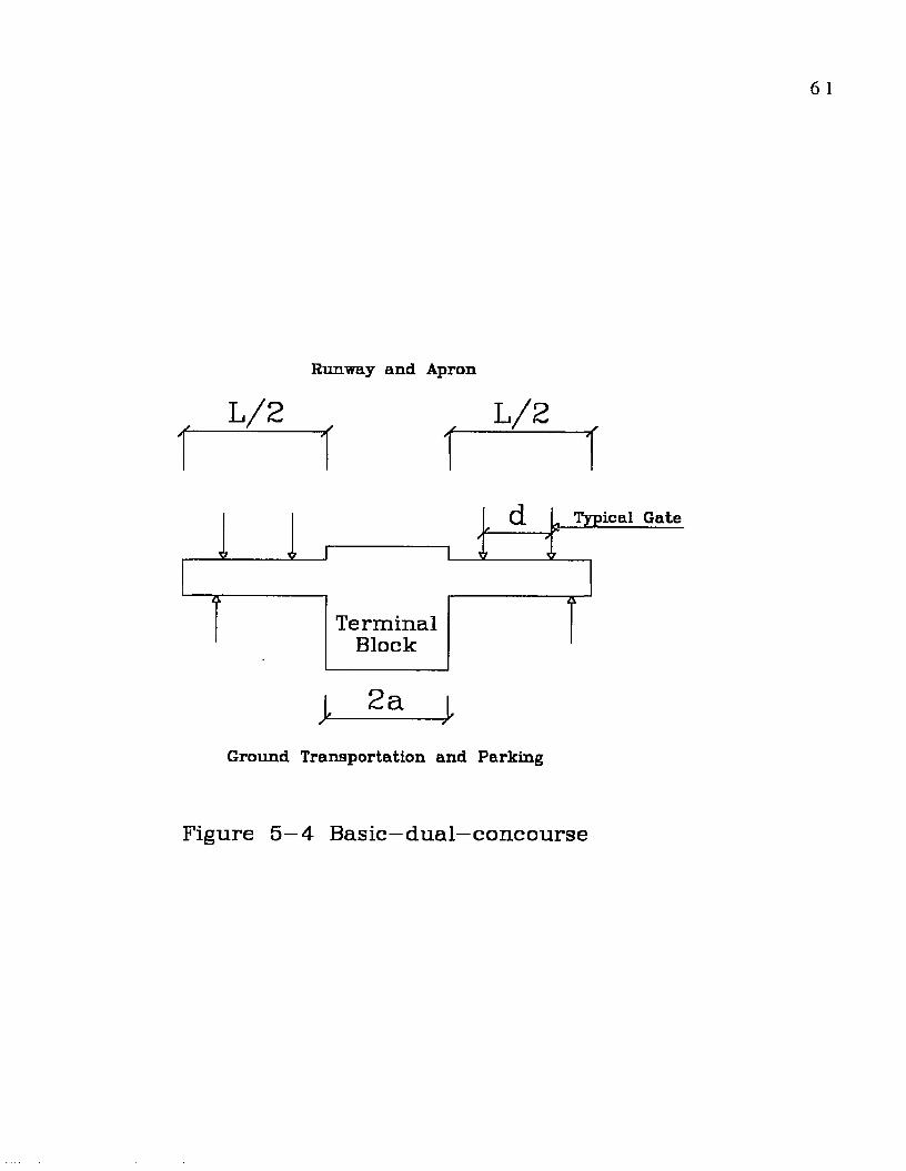
6 1
Runway and Apron
■ L / 2 - L /2 . - , y
d Typical Gate✓ /
T e rm in a lBlock
k2 a
Ground Transportation and Parking
Figure 5—4 B a s ic -d u a l—concourse

6 2
T-shaped dual-concourse
Figure 5-5 is a schematic diagram of a T-shaped duai-
concourse terminal. This configuration is similar to the basic dual
configuration (figure 3-4). A ircraft departure and arrival gates are
located not only on both sides of the concourses but also adjacent to
the terminal block. For a given number of gates, the T-shaped dual
concourse configuration requires a shorter concourse than does the
basic dual concourse, therefore, a reduction of passenger walking
distance can be realized by selecting the T-shaped dual concourse
co n figu ra tio n .
The departure and arrival gates are arranged uniformly over a
total distance of 4x+2a, or 2L. Thus, the expressions for the average
walking distance are:
4x+2a= 2L
x=4 2
Wo = x + a = L2 4 4
W1 = 1 . (x+a)= L + a3 6
W2 = (x + a) + a= x + 3a 2 2
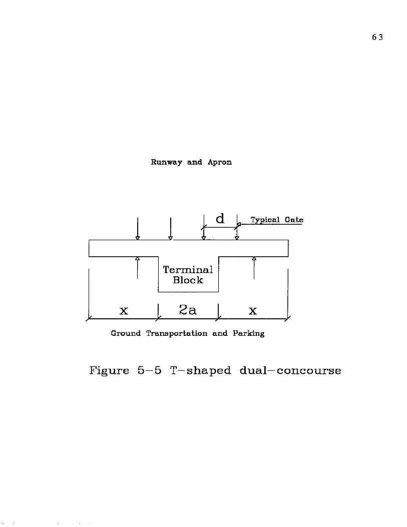
Runway a n d Apron
Typical Gate
T e r m in a lB lo c k
XM---------------)
2a*------------------ JX*--------- —--------- >
Ground Transportation and Parking
Figure 5 —5 T—s h a p e d d u a l—c o n c o u r s e

R ectanau lar-dua l-concourse
Figure 5-6 is a schematic diagram of a rectangular-dual
concourse configuration. This configuration can be considered a
generalization of the basic dual-concourse configuration, with the
addition of two pier concourses on each end, and replacing the
existing concourses with connectors to provide access from the
terminal block to each concourse and vice versa. The connectors are
ideal locations for moving walkways. In practice, some passengers
walk on the moving walkways and others stand. Both types of
passengers, as well as those who avoid the walkway, are not
considered in obtaining the passenger average walking distance. The
(c) distance (connector length) is added to the expressions for the
average walking distance. The angle between a connector and a
concourse can range from 0 to 90 degrees, depending on the shape of
the land area available for the terminal.
On the average, the expression for the average walking
distance for this configuration are:
Wo =(a + c) + 1 . L 2 2 2
W1 = 1 . L 3 2
W2 =(2 a +2 c) + 1 . (L + U2 2 2
=2(a+c) + L 2
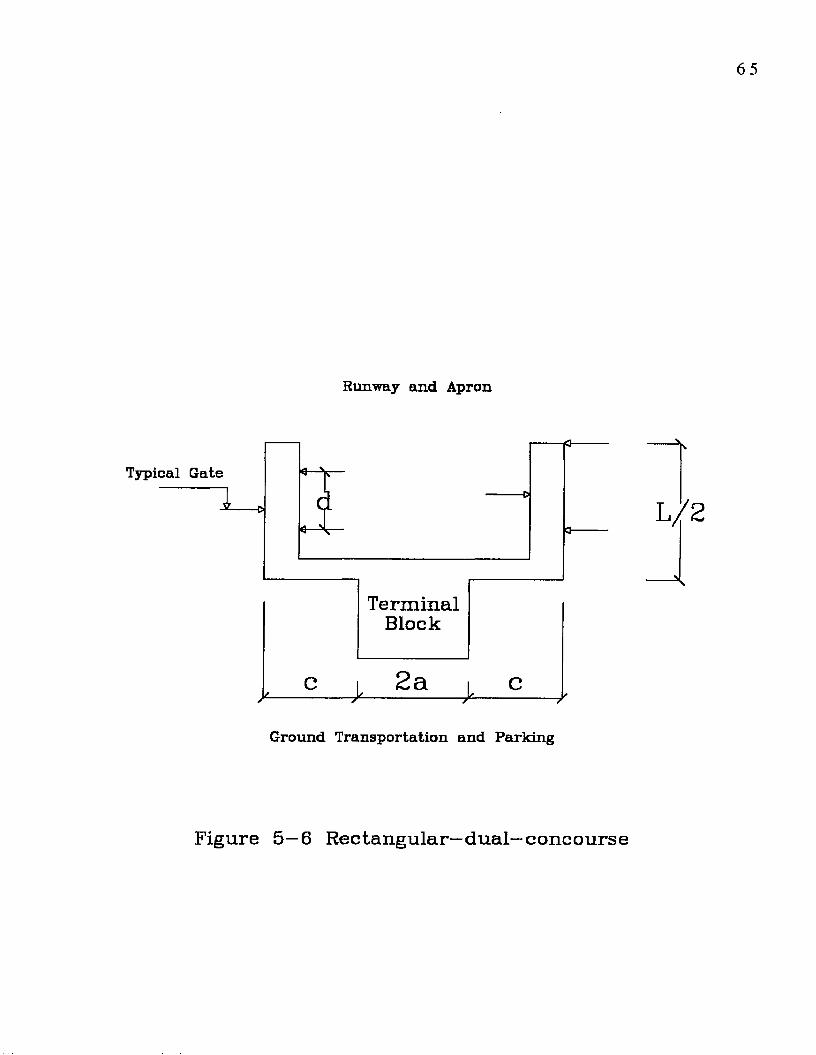
Runway and Apron
Typical Gate
* o
T e rm in a lB lock
c > 2 a i c
Ground Transportation and Parking
Figure 5 —6 R ectan g u lar—d u a l—concourse

5 .11 .2 Comparisons and Conclusions
The equations presented in the previous section for the four
terminal configurations, are used to compare the distances for the
three classes of passengers (Wo, W1, and W2). The following values
are assumed for the key parameters: 2L= 1200', 2a= 200', and c=
100'. The average walking distance of the average passenger for
each of the four terminal configurations and for each of the three
passenger classes are summarized in Table 5-3.
Term inalC o nfiguration
Wo (ft) W1 (ft) W2 (ft)S im p le -lin ear-concourse
300 4 0 0 400Basic-dual-concourse
200 100 500T-shaped dualconcourse
150 117 400Rectangular-dual-concourse
3 00 1 00 700
Table 5-3 Comparison of Walking Distances for Alternative Terminal
C on figu ra tions
Each of these configurations has specific applications based on
the composition of the passengers. Specifically, the proportions of
the three types of passengers will determine the overall average
walking distance for an average passenger.
For the three types of passengers, Table 5-3 shows that the
best term inal configuration for originating and destination

passengers is the T-shaped dual-concourse. For transferring
passengers within one concourse wing, the desired terminal
configurations are the Basic-dual-concourse or the Rectangular-
dual-concourse. Further, for transferring passengers between two
concourse wings, the preferred term inal configurations are Simple-
linear-concourse and the T-shaped dual-concourse. Consequently,
for the case of Jerusalem International Airport, predominant with
originating and destination passengers, the T-shaped dual-concourse
is the most suitable configuration for this type of passengers. This
configuration is used for the proposed Jerusalem International
Airport (see Appendix A.4).
5 .1 2 Conclusions
The objective of this chapter was to examine various factors
affecting a irport term inal configuration, with special emphasis
being placed on passengers walking distance. The purpose of
evaluating these factors was to develop a design for the proposed
Jerusalem International Airport. Based on the analysis of passenger
average walking distances of the selected configurations, the T-
shaped dual-concourse configuration was found to be the desired
configuration for prim arily originating and destination passengers.
This was the best-suited case for Jerusalem International Airport
Term ina l.
In addition to passenger walking distances, there are many
factors influencing term inal configuration and size. Each airport
has its own combination of individual characteristics to be
considered in configuring and sizing term inal facilities. Similarly,
each airline serving an airport has internal procedures, policies, and
staffing crite ria which influence fac ility planning. Further, it
should also be noted that the factors identified in this chapter may
not be the optimal set to evaluate all passenger term inal buildings.
6 9
6 Passenger Terminal Design
6.1 Introduction
The design of an airport passenger term inal is quite different
from the design of other typical buildings. It must not only
accommodate numerous and diverse functions but must also be
responsive to many changes. The passenger terminal design is a
challenging component of the airport to the designer because of its
physical location between term inal road and curb and aircraft parked
on the apron. It is a subsystem within the overall airport system
that should be designed dynamically to process passengers and their
baggage, vehicles, and aircraft as efficiently and comfortably as
possible through the requisite facilities. The passenger term inal
thus presents a complex task in planning and design.
The passenger term inal provides an interface between the
landside and airside of the air transport systems (Hart 1985).
1. At the landside; passengers arrive and depart by ground
transporta tion, requiring ground transporta tion fac ilities.
2. At the airside; passengers arrive and depart by aircraft,
requiring runway and taxiway facilities.
3. Between the airside and landside; passengers and their baggage
are to be processed through a sequence of functions, requiring
ap ron -te rm in a l fa c ilit ie s .
The difficulty in designing a passenger term inal occurs when
these three elements are combined into one comprehensive plan

which creates unexpected dim ensional conflicts. These conflicts
occur at the airside on account of the dimensions and volume of the
aircraft, and at the landside due to the size and volume of ground
transportation vehicles. However, when tra ffic volume reach
certain levels, the dimensions at the airside and landside w ill
exceed those required for the term inal.
D imensional conflicts and space requirements also have an
impact in designing a passenger term inal when the three primary
activities are combined into one com prehensive plan. Space
requirements for a passenger term inal building are governed by
dimensions of people, baggage, and equipment. Facilities must be
designed to accommodate people and baggage in motion and at rest.
Passenger walking distances must be w ithin generally accepted
standards: less than 1000 ft. between points of term inal entry,
ticke t check-in, and a ircra ft gates fo r orig inating tra ffic , and
between a ircra ft gates for transfer passengers (Hart 1985).
Space requirem ents for ground transportation fac ilities are
governed by the dimensions, characteristics, and volume of ground
transportation vehicles, predom inantly those of the autom obile. The
road system must be designed to accommodate the flow of vehicles
and provide adequate access to the term inal. The length of curb at
the term inal fron t is determ ined by the characteristics and number
of vehicles to be processed during average peak time. Nevertheless,
it has been noticed that, as traffic volumes increase, the required
curb length may become longer than the effective term inal frontage,
which then requires a special solution. Moreover, building entrances
and exits must be located in proper relation to vehicular stops.
Curbside platforms must be provided for transition of passengers
and baggage between vehicles and the building.
Space requirements for apron aircraft parking are governed by
dimensions of airplanes such as wingspan, length, height, and
clearances. The facility must be designed for current and future
aircraft parking and maneuvering, and for enplaning and deplaning of
passengers.
In addition to the determined terminal building configuration
that minimizes the passenger average walking distances at medium
hub airports, this chapter will also considers characteristics of
three other selected airports in the United States. The airports
were selected based on their annual enplanement, and to provide
basic design guidelines, in developing the optimum configuration,
and to suit the objective of this thesis.
6.2 Selected Airports (Case Studies)
Three case studies, Sacramento Metro, Reno Cannon
International, and Tucson International airports are presented to
strengthen the application of the proposed design configuration of
the hypothetical airport term inal building. In the follow ing section,
brief variations in the analysis of airports' physical characteristics
with respect to the ir configuration, term inal block area, expansion
capability, and their relationship are presented. These
characteristics are only used to enhance the design of the selected
terminal configuration, and to provide guidelines to develop an
adequate building program.

7 2
The selection of the three medium size airports was initially
based on the average number of annual enplaned passengers of four
major international airports in The Middle East (see table 3-1): the
international airport traffic in 1990 in Israel, Cyprus, Jordan, and
Syria. The average number of enplaned passengers in 1990 at these
airports was 1,009,589. Further, this number was used as a
determining factor to select other airports in the U.S. with sim ilar
annual enplaned passengers. A irport activities statistics prepared
by the FAA provide annual summaries of enplaned passengers at
small, medium, and large air traffic hubs in the U.S. (Appendix B).
The three selected airports are: Sacramento Metro, Reno Cannon
International, and Tucson International (Medium Air Traffic Hubs).
The enplaned passenger volumes of each airport is relatively close
to the average number of the four airports in The Middle East. In
addition, these three airports have different term inal configurations
which facilitates a comparative analysis of alternate
co n fig u ra tio n s .
6 .3 Analysis and Schemes of Case studies
In this section, the analysis and schemes of case studies are
briefly evaluated in terms of their configuration, term inal block
area, gate spacing, and physical expansion capability.
6.3.1 Sacramento Metro Airport
Currently, there are two terminals at Sacramento Metro
Airport. On the eastern portion of Metro Airport's term inal area, a
new term inal is under construction with a d ifferent configuration.
7 3
This east term inal configuration w ill be used for the case study
(Figure 6-1).
C o n figu ra tion :
The term inal configuration is a Y Pier. This figure is slightly
different from the proposed east term inal. In the proposed terminal
(stage 1), the right concourse is shorter than the left. Nevertheless,
in this thesis it is assumed that both concourses are identical in
length, with one pier connector attached to the term inal block.
Term inal Block:
The term inal is centralized with two separate areas: ticketing
(check in) and baggage claim. Both areas have direct relationship to
ground transporta tion .
Gate Spacing:
The maximum spacing between gates is 160 linear feet, and
the minimum is 50 linear feet. The number of gates at the
concourses are 11.
Expansion C apability :
Unless expansion space is expressly planned, it may be
impossible to extend the main term inal block by expanding the width
w ithout changing the concourse configuration. For example, joining
two term inal blocks linearly would create aircraft congestion and
reduce aircraft maneuvering capability because of the enclosed area
between piers. Joining the term inals must also be positioned
carefully so that aircraft flow or access modes do not conflict. The
most reasonable expansion usually occurs by extending piers or
concourses. This also needs to be preplanned to avoid interfering
with the taxiways or other piers. Figure 6-2 shows different

Runway
T yp ica l G a te
Apron
Apron
Terminal Block
Apron
Ground T ra n s p o r ta t io n and Parking
F ig u re 6 -1 S a c ra m e n to M e t r o A i r p o r t ( E a s t Term inal)
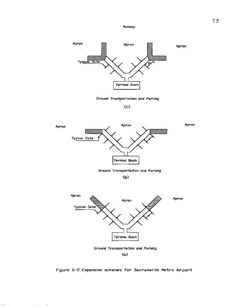
Runway
Apron
Apron Apron
Typical L a te
Tern Inal Block
Ground Transportation anol Parking
Cc)
Apron
Typical Gate
Terminal Block
Ground Transportation and Parking
(b>
ApronApron
Typical Gate
Terminal Block
Ground Transportation and Parking
(a )
Apron
Apron
Apron
Figure 6 - 2 Expansion schemes f o r Sacram ento M etro A irp o rt
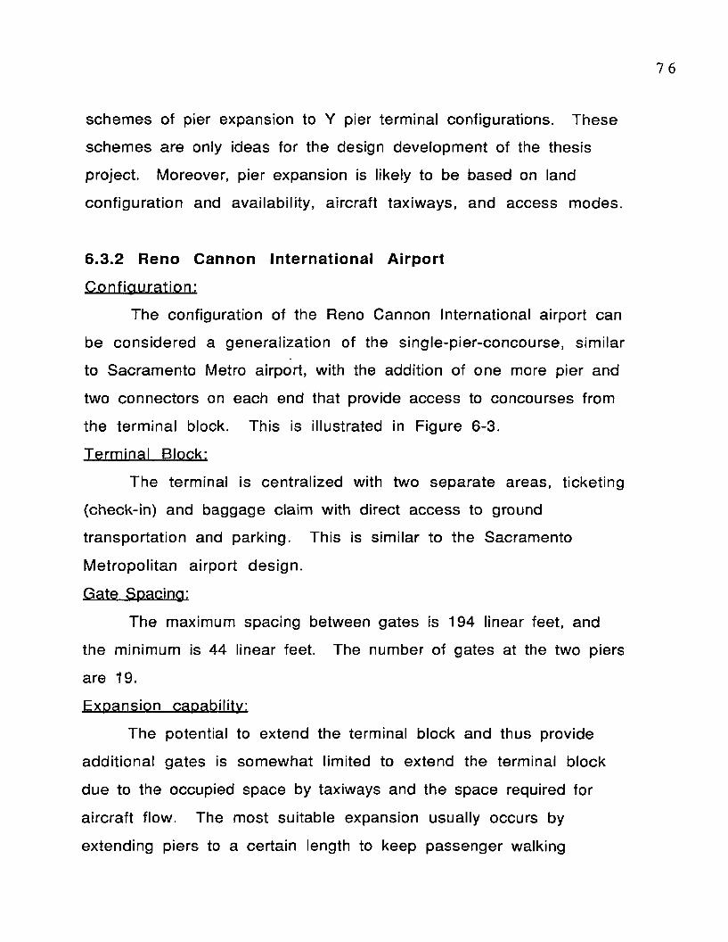
7 6
schemes of pier expansion to Y pier term inal configurations. These
schemes are only ideas for the design development of the thesis
project. Moreover, pier expansion is likely to be based on land
configuration and availability, aircraft taxiways, and access modes.
6.3.2 Reno Cannon International Airport
C o n fig u ra tion :
The configuration of the Reno Cannon International airport can
be considered a generalization of the single-pier-concourse, sim ilar
to Sacramento Metro airport, with the addition of one more pier and
two connectors on each end that provide access to concourses from
the term inal block. This is illustrated in Figure 6-3.
Term inal Block:
The term inal is centralized with two separate areas, ticketing
(check-in) and baggage claim with direct access to ground
transportation and parking. This is sim ilar to the Sacramento
M etropolitan airport design.
Gate Spacing:
The maximum spacing between gates is 194 linear feet, and
the minimum is 44 linear feet. The number of gates at the two piers
are 19.
Expansion capability:
The potential to extend the terminal block and thus provide
additional gates is somewhat limited to extend the term inal block
due to the occupied space by taxiways and the space required for
a ircraft flow. The most suitable expansion usually occurs by
extending piers to a certain length to keep passenger walking
7 7
Runway
Apron
Apron
Typical Connector
rrd0 -
Z
d /2 —*
Terminal BlockTypical Connector
Ground Transportation and Parking
A p ro n
F i g u r e 6 - 3 Reno Cannon I n t e r n a t i o n a l A i r p o r t
7 8
distances acceptable and not reaching the maximum. Figure 6-4
shows different schemes of pier expansion to rectangular-dual-
concourses.
6.3.3 Tucson International Airport
C onfigura tion:
A schematic representation of the Tucson International airport
is presented in Figure 6-5. This figure is different from the four
basic configurations discussed in chapter two. However, this
configuration is sim ilar to the rectangular-dual-concourse concept
with respect to the two connectors between concourses and
terminal block. In addition, it is assumed that both concourses are
identical in length, and in number of gates. The layout can be
idealized as a modified dual-pier concept as well.
Terminal Block:
Is a two level terminal, one for ticketing and one for baggage.
Both levels have direct relationship to ground access.
.Gate., Spacing;
The maximum spacing between gates is 168 linear feet, and
the minimum is 17 linear feet. The number of gates is 17.
Expansion Capability.
It is frequently impossible in such cases to extend the
terminal block without changing the configuration of the piers. If
this is done, the dead space created between the terminal and piers
would result in inefficiencies. The desirable expansion within the
existing condition may occur by extending piers linearly
(figure 6-6).

Runway
Apron Apron Apron
Typleat Connector Typical ConnectorTerminal Block
Ground T ra n s p o rta t io n and ParkingCci
Apron
Terminal Block
Ground T ra n s p o r ta t io n and Parking
ct>>
Apron
Apron
x : Typical Connector
Terminal Block
Ground T ra n s p o r ta t io n and Parking
<a>
F ig u r e 6 - 4 Expansion sc h e m e s f o r Reno Cannon
I n t e r n a t i o n a l A i r p o r t

Runw
ay
8 0
a
mCl
CDc-2£L.aQ_
L.OD.inc0&.
3O£_aFi
gure
6-
5 Tu
cson
In
tern
ati
on
al
Air
po
rt
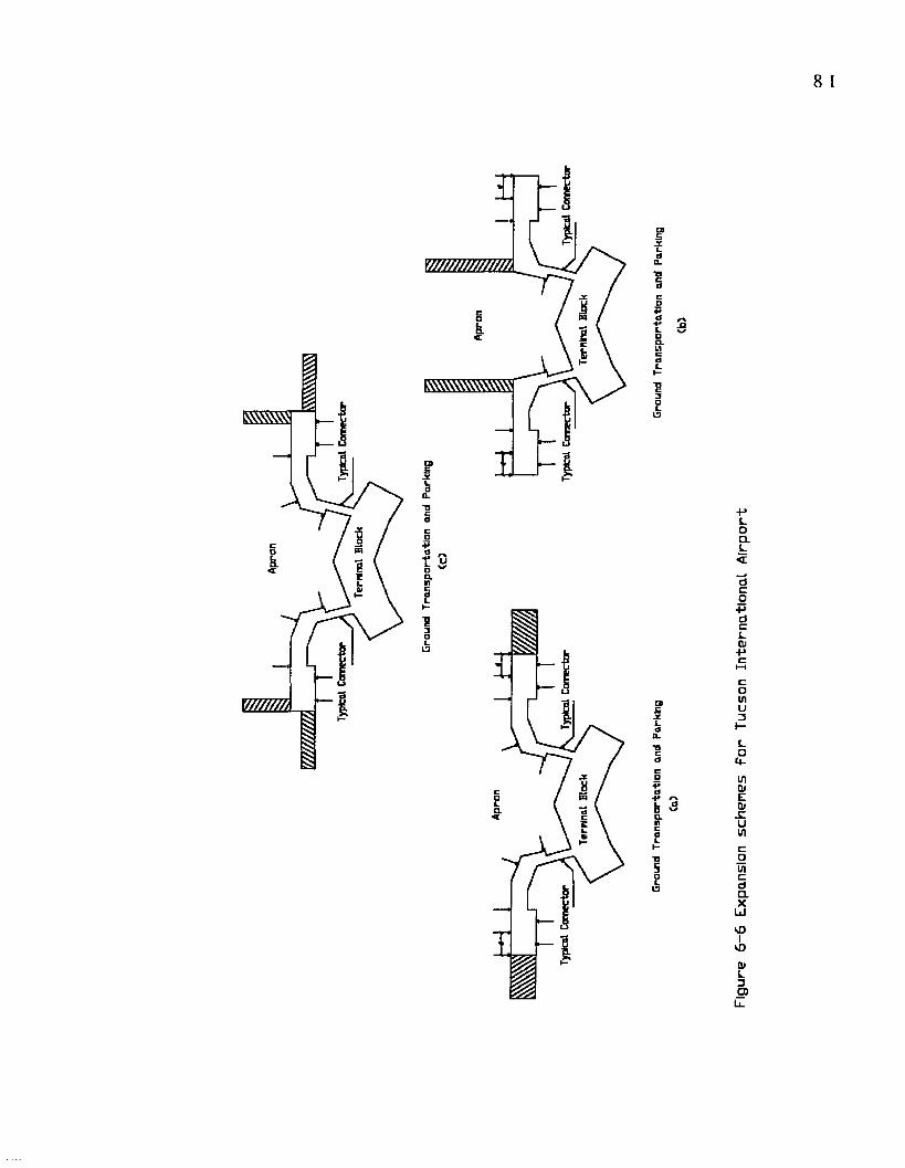
8 1
Q.
W ////A
a.
uca
t ub ~an
■g3
pqa
o•h
t 3L K/ DCLin
J£L0
CL
TJ5aL
13
Figu
re
6-6
Expa
nsio
n sc
hem
es
For
Tucs
on
Inte
rnat
iona
l A
irp
ort

But this could pose problems with maintaining acceptable walking
d is tances.
6 .4 Airport Layouts and Characteristics
The follow ing characteristics of the three a irports examined
in this chapter as case studies (Table 6-1) are typical facilities
with differing degrees or ranges of space requirement and service.
In planning and design of a new airport or expanding an existing
term inal, It is im portant for the A rchitect to identify these
facilities, understand the role of each element in the typical
term inal system, and establish the ir degrees of service under the
peak demand conditions. Table 6-1 was conducted according to
drawings and informations provided by the airport's authorities.
However, the objective of this table was: for comparison purposes,
to compare and analyze three existing airport facilities, to
understand the amount of space required for these facilities
depending on their function and location in the airport. Also, it
should be noted that these characteristics are approximate and will
be used only as basic guideline elements to be identified and
analyzed in the programming development for the proposed term inal
building design at Jerusalem Air Terminal (Appendix A).

Table 6-1 Summary Characteristics of Selected Airports
RENO TUCSON SACRAMENTO
International Yes Yes Yes
Annual Enplanement, 1990 1343619 1263509 1737096
Annual Aircraft Departure 216 09 20201 39 7 2 3
Passenger per Aircraft 62.2 62.5 43.8
Terminal Gross Area 339,771 S.F. 270,000 S.F. 240,000 S.F.
Terminal Block Area 127,500 S.F. 106,720 S.F. 79,002 S.F.
Ticket Counters 310 L.F. 350 L.F. 180 L.F.
Ticketing Counter Area 3,100 S.F. 3,690 S.F. 2,167 S.F.
Ticketing Lobby 16,000 S.F. 16,100 S.F. 11,850 S.F.
Holding Rooms 1 7 1 4 1 1
Baggage Make up 21,500 S.F. 21909.3 S.F. 16,518 S.F.
Baggage Claim 11,095 S.F. 12,670 S.F. 25,765 S.F.
Baggage Claim Lobby 10,174 S.F. 12,115 S.F. 8,630 S.F.
Airline Operation Area 30,600 S.F. 27,953 S.F. 30,394 S.F.
Terminal Depth 150 L.F. 145 L.F. 154 L.F.
Terminal Width 850 L.F. 736 L.F. 513 L.F.
Concourse Width 75 L.F. 85 L.F. 108 L.F.
Connector Depth 96 L.F. 170 L.F. 75 L.F.
Connector Width 62 L.F. 35 L.F. 58 L.F.
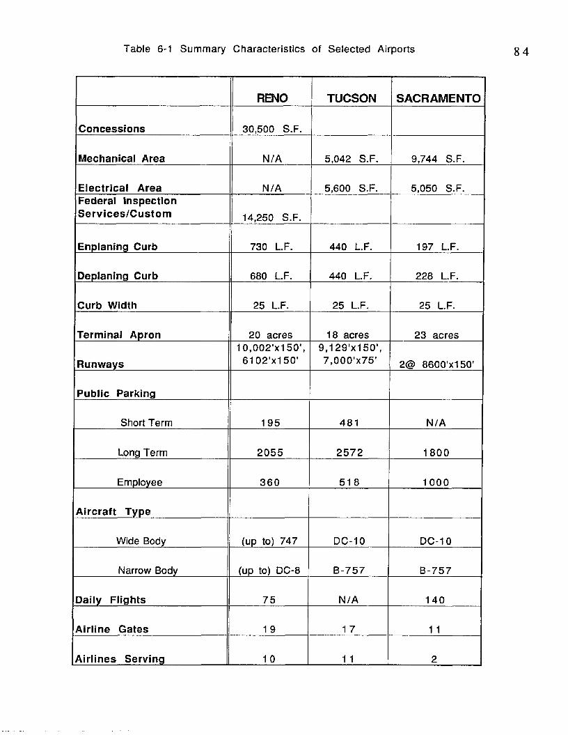
Table 6-1 Summary Characteristics of Selected Airports
RENO TUCSON SACRAMENTO
Concessions 30,500 S.F.
Mechanical Area N/A 5,042 S.F. 9,744 S.F.
Electrical Area N/A 5,600 S.F. 5,050 S.F.Federal Inspection Services/Custom 14,250 S.F.
Enplaning Curb 730 L.F. 440 L.F. 197 L.F.
Deplaning Curb 680 L.F. 440 L.F. 228 L.F.
Curb Width 25 L.F. 25 L.F. 25 L.F.
Terminal Apron 20 acres 18 acres 23 acres
Runways1 0 ,002 'x150',
61 02'x1 50'g .^ 'x is o ' ,7,000 'x75 ' 2@ 8600'x150'
Public Parking
Short Term 195 481 N /A
Long Term 2055 257 2 1800
Employee 360 5 1 8 1000
Aircraft Type
Wide Body (up to) 747 DC-10 DC-10
Narrow Body (up to) DC-8 B-757 B-757
Daily Flights 75 N/A 140
Airline Gates 1 9 1 7 1 1
Airlines Serving 1 0 1 1 2
85
6 .5 Conclusion
The selection of the three case studies was based on the
average number of annual enplaned passengers of four major
international airports in the Middle East adjacent to the proposed
term inal at Jerusalem. The physical characteristics of the case
studies presented in this chapter were used to strengthen the design
application, and to provide basic guidelines to develop a desired
building program for the proposed Jerusalem International Airport.
7 Conclusions and Recommendations
7.1 Conclusions
The planning and design of a terminal building is a complex
task because of the multitude of factors that are involved. Three
major traffic entities need to be combined when dealing with the
landside/airside planning and design: vehicles, passengers, and
aircraft. Therefore, selecting a terminal configuration to satisfy
these tra ffic entities is very critical.
To determine the appropriate airport size for the proposed
airport at Jerusalem,(small, medium, large), the average number of
annual enplaned passengers of the four adjacent airports in The
Middle East were used. Once the size was determined, three U.S.
airports were selected as case studies to aid in the programming
process. The physical and spatial characteristics were used to
provide guidelines to develop the terminal building layout for the
proposed Jerusalem International Airport.
Based on the annual enplanements, a medium sized airport was
suitable for the region. This thesis examined some of the main
factors influencing medium sized term inal building configuration,
with respect to their function and operation. It investigated four
se lected/centra lized term inal configurations specifica lly in terms
of their influence on passenger walking distances. The T-shaped
dual concourse was evaluated to be the most suitable layout and was
adopted for the design of the proposed Jerusalem International
Airport. This is based on the fact that this airport will have the
majority of passengers being either arriving or departing and not
t ra n s fe rr in g .
7 .2 Recommendations for Future Work
The factors affecting term inal layout evaluated in th is thesis
were considered in the design development of the proposed
Jerusalem International Terminal. They were evaluated based on
the ir general function and operation in term inal building planning
and design. The performance of these factors in determining
term inal configuration at selected airports may be another area
where more research is required.
The analysis of passenger average walking distance were
based on some simplifying assumptions. The linear frontage of the
gates was identical for all four term inal configurations selected in
this research. Further, the number of gates and the ir spacing were
also uniform ly arranged along the length of the concourse. For
future application, one may relax these assumptions and use more
than one type of gate (which would affect gate size and spacing).

88
REFERENCES
Ashford, N. and Paul H. Wright (1992), Airport Engineering. New York, John Wiley and Sons, Inc.,321.
Ashford, N., Bennetts, D., and P. Mcginity (1976), "PassengerBehaviour and Design of Airport Terminals", National Academy of Science, Transportation Research Record 588, pp 18-26.
Babic, O., D.Teodorovic and V. Tosic (1984), “Aircraft StandAssignment to Minimize Walking” , Journal of Transportation Engineering, Vol. 110,No. 1, pp 55-66.
Bandara, S. and S.C. Wirasinghe (1989), "Airport Gate Position Estimation Under Uncertainty", Airport Landside Planning Techniques, Washington, D.C., Transportation Research Record, pp 41-48.
Bandara, S. and S. C. Wirasinghe (1992), "Walking Distance M inim ization for A irport Terminal Configuration", Transportation Research, Airport Landside Planning and Operation, Vol. 26A, No 1, pp 59-74.
Baron, P. (1969), "A Simulation Analysis of Airport TerminalOperations", Transportation Research, Vol. 3, No 4, pp 481-491.
Blankenship, Edward G. (1974), The Airport. New York: Praeger Publishers, Vol. 28.
Blow, C. J. (1991), Airport Terminals. Oxford.
Blow, C. J., Scott Brownrigg and Turner (1993), " Do Airport get The Annual Review of Civil Aviation, Airport and Airline Ground Management, Sterling Publishing Group, PLC, London, pp 33-35
Braaksma, J.P. and J.H. Shortreed (1975), "Method for Designing Airport Terminal Concepts", Transportation Engineering Journal, A.S.C.E., Vol. 101, No TE2, pp321-335.

Braaksma, J.P. (1977), "Reducing Walking Distances at ExistingAirports", Airport Forum, W iesbaden, W. Germany, Bauverlag, pp 135-142.
deNeufville, R. and I Rusconi-clerici (1978), "Designing A irport Term inals for Transfer Passengers", Transportation Engineering Journal, A.S.C.E., Vol. 104, No TE6, pp775-787.
Hart, W. (1985) The A irport Passenger Terminal. John Wiley and Sons, New York.
Heathington, K.W. and Don H. Jones (1975), "Identification of Levels of Service and Capacity of Airport Landside", In special Report 159: Airport Landside Capacity, TRB, National Research Council, Washington, D.C., pp 72-91.
Horonjeff, R. and Francis X. Mckelvey (1983), Planning and Design of A irp o rts . 3rd edition. Mcgraw-Hill Book Company, New York.
ICAO (1990), A irport Traffic, D igest of S tatistics No 383,International Civil Aviation Organization, M ontreal, Quebec, Canada, 1990.
Lemer, A. C. (1992), "Measuring Performance of Airport Passenger Term inals, Transportation Research, Vol. 26A, No 1, pp 37-45.
Martel, N. and P.N. Senevirante (1990), "Analysis of Factors Influencing Quality of Service in Passenger Terminal Buildings", Airport Terminal and Landside Design and Operation, Washington, D.C., National Research Council, Transportation Research Record, 1273, pp 1-10.
Mumayiz, S.A. (1990), "Overview of A irport Term inal SimulationModels", Airport Terminal and Landside Design and Operation, Transportation Research Record 1273, TRB,National Research Council,W ashington, D.C., 11-20.
Mumayiz, S. A. and N. Ashford. (1986), "Methodology for Planning and O perations Management of A irport Term inal Facilities", Washington, D.C., Transportation Research Record, 1094, pp 2 4 -3 5 .

9 0
Muller, C. (1987), " A Framework for Quality of Service Evaluation at A irport Terminals", Ph.D. Dissertation, University of California, Berkeley.
Odoni, Amedo R. and Richard De Neufville (1992), "PassengerTerminal Design", Transportation Research, Vol. 26A, No 1, pp 2 7 -3 5 .
Robuste, F. (1991), "Centralized Hub Terminal Geometric Concept; 1: Walking Distance", Transportation Engineering Journal of ASCE, Vol. 117, pp 143-158.
Tosic, V. (1992), "A Review of Airport Passenger TerminalOperations Analysis and Modelling", Transportation Research, Vol. 26A, No 1, pp 3-26.
Transportation Research Board (1987), Special report 215,Measuring Airport Landside Capacity. National Research Council, Washington, D.C.
U.S. Department of Transportation (1983), "Airport Design Standards-Transport Airports", Federal Aviation Administration, Washington, D.C., Advisory Circular, AC 1 5 0 /5 3 0 0 -1 2 .
U.S. Department of Transportation (1985), "Airport Master Plan", Federal Aviation Administration, Washington, D.C., Advisory C ircular, AC 150/5070-6A.
U.S. Department of Transportation (1980), "Planning and Design of Airport Terminal Facilities at Nonhub Locations", Federal Aviation Administration, W ashington, D.C., Advisory Circular AC 150/5360-9,
U.S. Department of Transportation (1988), "Planning and DesignGuidelines for Airport Terminal Facilities", Federal Aviation Administration, Washington, D.C., Advisory Circular AC 1 5 0 /5 3 6 0 -1 3.
U.S. Department of Transportation (1990), A irport Activ ityStatistics of Centralized Route A ir Carriers, Federal Aviation A d m in is tra tio n .

U.S. Department of Transportation (1976), “Techniques forD ete rm in ing ,A irport Airside Capacity and Delay” . Federal Aviation Administration, Washington, D.C., Report FAA, RD-74- 124.
Wirasinghe, S.C., S. Bandara, and U. Vandebona (1987), "Airport Terminal Geometries for Minimal Walking Distance", In N.H. Gartner and H. M. Wilson, (Eds), Elsevier, Sci Publishing Co.,Inc., New York, N.Y^Transportation and Traffic Theory, pp 483- 502.
Wirasinghe, S.C. and U. Vandebona (1987a), "Passenger Walking D istance Distribution in S ingle-and Dual-Concourse Centralized A irport Term inals", Air Transportation,Washington, D.C., Transportation Research Record, 1147, pp 4 0 -4 5 .
Wilkes, J.A. and Robert T. Packard (1988), Encyclopedia ofArchitecture Design. Engineering, and Construction. New York, John Wiley and Sons, Inc., Vol. 4.
Yagar, S. (1973), "Analysis of Passenger Delays at A irportTerminals", Transportation Engineering Journal, A.S.C.E., Vol. 99, No TE4, pp 909-921.

APPENDICES

APPENDIX A
DESCRIPTION OF HYPOTHETICAL AIRPORT

A.1 Building Program for Jerusalem International Airport
Program Introduction
Project Sum m ary and G eneral Description. The proposed site fo r
Je rusa lem In te rna tiona l A irp o rt cons is ts of app rox im a te ly 2300
acres of fla t land. The need fo r this A irport is to accom m odate the
pro jected transporta tion dem and fo r the em erg ing state of
Palestine. The sum m ary descrip tion of spaces, program
requirem ents and goals provided in th is program docum ent are
cons is ten t with the scope of the design pro ject. It is necessary for
the designer to w ork w ith in the determ ined con figura tion to g ive a
desirab le passenger w alk ing d istance. In addition, the sum m ary
descrip tion of spaces and program requirem ents is based on the
analys is of three existing a irports (case stud ies): Reno Cannon
In ternationa l A irport, Sacram ento M etro A irp o rt (East Term ina l), and
Tucson Internationa l A irport. Further, the predom inant type of
passengers used at the proposed Jerusa lem Internationa l A irport is
o rig ina ting and destina tion passengers.
Goals
1. O ne of the goals of this thesis pro ject is to provide an a irport
te rm ina l bu ild ing design tha t m in im izes passenger w a lk ing d is tance .
The com ple ted design should facilita te and support the program
ob jec tives and ac tiv ities , ra ther than im pose lim ita tions and crea te
de fic ienc ies tha t users m ust overcom e.
Z To provide a flexib le design for the com m on continuous change in
a ir trave l dem and.

95
& To create a visual, symbolic, and ceremonial center of the total
airport complex as well as a gateway to Jerusalem.
The building should serve the community, and be a cultural center
for Palestine.
4, To create a new terminal building as an internal part of
community life of the three existing cultures.
The terminal should have a strong sense of community among the
three cultures: Christian, Muslim and Jews. Airport users and the
public may agree that achieving a stronger understanding of the
three cultures and knowledge of others will enhance their
com m unity life.
iL To provide the country with a design that is appropriate to the
region and site.
The building should be responsive to climate and its context.
& The design of the airport terminal shall project a cultural image.
The Architecture of the airport term inal shall reflect the image of
Jerusalem with contemporary Architecture appearance. It should
have a youthful image, a statement of freedom, and a new image of
Pa lestine.
In addition, the program assumes that building design will
incorporate the determ ined configuration, from previous chapters, to
satisfy the objective of this thesis project.
Geographical Setting
The proposed site for the airport is situated at an elevation of
approximately 2700 feet above sea level. The site is located 36
miles east of the Mediterranean Sea in about the center of Palestine
9 6
between Jerusalem and Ram Allah. The terrain of the area around
Jerusalem is punctuated by hills and valleys. From the south, east,
and west the proposed site location is a flat plain. The site is
bordered by a divided highway on the east (north-south road running
from Samaria to Judea); by Tel Aviv roadway on the south; and Abu
Algadid on the north and west. Based on existing conditions, the
primary traffic access to the existing runway is from the divided
highway (see Site plan, Appendix A.4).
Population
According to World Year Book 1991, the estimated population of
Israel and Palestine (1989) is about 4,500,000 million people of
different faiths (Christians, Muslims, Jews, Druze, and others). Over
490,000 people reside in Jerusalem, and the area is characterized as
high density.
History and/Tourism
Due to the religious significance of Israel and Palestine tourism is
very high, especially in Jerusalem and Beth Lehem. The importance
and location of Jerusalem have made it a meeting point between the
eastern and the western worlds. It has always gained strength and
renown from the moral and religious precepts taught within its
walls. Today Jerusalems religious atmosphere still permeates the
city through a variety of faiths. The "Old City" of Jerusalem is
presently divided into four quarters: Christian, Muslim, Jewish, and
Armenian. With this great history, Jerusalem has gained
international interest, and visitors come from all over the World.
9 7
According to the Statistical Survey of Europe World Year Book 1991,
over 1,424,000 tourist visited Israel and Palestine in 1989.
C lim a te
This area known historically as the Samarian Hills has numerous
small fertile valleys. It has a Mediterranean climate with long, hot,
dry summers, and short, cool, rainy winters. January is the coldest
month with temperatures from 5 C to 10 C, and August is the hottest
month at 18 C to 38 C. There is sunshine 80 percent of the year.
About 70 percent of the average rainfall is between November and
March; June through August are often dry. Rainfall is unevenly
distributed, decreasing sharply as one moves southward. Rainfall
varies from season to season and from year to year particularly in
the south. During January and February, it may take the form of
snow at the higher elevations of the central highlands which
includes Jerusalem. The region is not generally windy. During the
spring months, west and northwesterly breezes are predominate, and
summer breezes are considered an asset.
It is expected tha t the airport term inal building design will
recognize that protection from the Sun is essential for much of the
day during the summer months at the very least. In contrast, during
the w inter months the lower temperatures make sunshine highly
de s ira b le .
Geological Consideration and Soil
Geologically, Jerusalem together with Beth Lehem and Hebron in the
south, lie on the eastern edge of the Cenomanian Limestone

9 8
Highlands. These limestone highlands run north to south and make up
the central ridge of the Country. For site design, the designer may
assume that the surface and subsurface will allow for relatively
easy excavation and that the bearing capacity of subsurface soils is
adequate for the terminal and runway construction.
Site Issues
For the purpose of designing an international airport term inal
building, the designer has designated a site that has been used in the
past as the Jerusalem Airport. Presently, the site has one runway
which is sometimes used for small aircraft and training. It is
expected tha t the site design of the airport w ill utilizes this
existing runway with its orientation for the prevailing
west/northwest winds. There is no term inal building to provide
services to Jerusalem and the West Bank and the construction of
new terminal is required. The existing runway is northeast of the
proposed terminal location and will need some modification to meet
the requirements of the new term inal building.
V iews. There are views of the horizon to the west and the mountain
ranges to the north.
Adjacent Pevelopm ents/C ities/or Build ings. The new Israeli
settlement to the southeast of the proposed site is expected to
remain. However, due to anticipated aircraft noise and future
expansion of parking and the ground transportation system, it will
be demolished. To the north is the city of Ram Allah which sits on

9 9
the hills with an elevation higher than the airport site and has a
population of 50,000 people. Part of the city is likely to be affected
by aircraft noise, and it should be considered in future expansion.
T ra ffic C irculation. The main entrance will be from the north/south
divided highway and a secondary entrance from the east/west Tel
Aviv roadway. Generally, airport ground transportation system
impacts the design of the term inal building and its future expansion.
The divided highway has four lanes and carries a large volume of
traffic. A major access system to the term inal should be designed
w ithout interfering with the tra ffic flow. In contrast, Tel Aviv
roadway has small traffic volume and another access is required for
e ffic ient airport term inal circulation. In addition, the design of the
ground transportation system should be effic ient and adequate to
meet airport needs and services.
P ark ing . According to the FAA Advisory C ircular 150/5360-13, the
parking requirements for every one million enplaned passengers are
950 stalls. A projected demand of 900 parking spaces for this
term inal is anticipated. The ground transportation parking shall be
located directly across the term inal roadway from the term inal
building. Short term parking shall be the closest available to the
term inal building entrance, with long term parking farther removed.
Specialized parking for rental cars, charter buses, taxis, and
employees should be provided for in design development. Rental car
return lots, storage, and service areas are generally adjacent to
te rm ina l bu ild ing.
100
Service/Loading. An adequate/convenient access shall be provided
to the terminal building and other facilities for services and
loading..
Special Considerations
Security Fencing. A minimum, of number 10 gauge, galvanized steel
chain link fabric shall be installed to a height of 8 feet topped with
barbed wire overhang.
Architectura l Treatm ent. The architecture of the airport terminal
building must contribute to the architectural and cultural heritage
of the local communities: Christians, Muslims, and Jews. It should
encourage the use and development of art and architectural
treatments that reflect local customs and community history. This
should be accomplished in conjunction with a functional, safe, and
e ffic ien t a irport term inal facilities.
Architectural treatments for the exteriors of the terminal building
and structures should avoid materials and configurations which can
interfere with airport's operational activities. The materials used
should be controlled and appropriate to this particular region and
site setting.
Mechanical Systems. Hot and chilled water will be available at the
site from a central plant, and the final route for this supply has not
been determined.
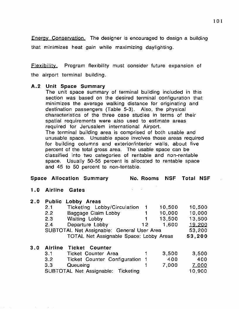
101
Energy Conservation. The designer is encouraged to design a building
that minimizes heat gain while maximizing daylighting.
F lex ib ility . Program flexibility must consider future expansion of
the a irport term inal building.
A .2 Unit Space SummaryThe unit space summary of terminal building included in this section was based on the desired terminal configuration that m inimizes the average walking distance for originating and destination passengers (Table 5-3). Also, the physical characteristics of the three case studies in terms of their spatial requirements were also used to estimate areas required for Jerusalem international Airport.The terminal building area is comprised of both usable and unusable space. Unusable space involves those areas required for building columns and exterior/in terior walls, about five percent of the total gross area. The usable space can be classified into two categories of rentable and non-rentable space. Usually 50-55 percent is allocated to rentable space and 45 to 50 percent to non-tentable.
Space Allocation Summary No. Rooms NSF Total NSF
1.0 Airline Gates
2 .0 Public Lobby Areas2.1 T icketing Lobby/C ircu la tion 1 10 ,5002.2 Baggage Claim Lobby 1 10 ,0002.3 Waiting Lobby 1 13 ,5002.4 Departure Lobby 12 1 ,600SUBTOTAL Net Assignable: General User Area
TOTAL Net Assignable Space: Lobby Areas
3.0 Airline Ticket Counter3.1 Ticket Counter Area 1 3 ,5 003.2 T icket Counter Configuration 1 4003.3 Queueing 1 7 ,000SUBTOTAL Net Assignable: Ticketing
10.500 10,00013.5001 9 .20053 .200
5 3 ,2 0 0
3,500400
7.00010,900
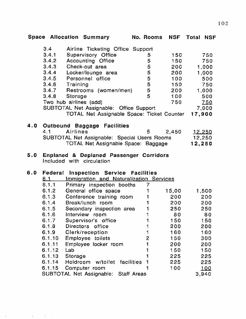
1 0 2
Space Allocation Sum m ary No. Rooms NSF Total NSF
3.4 A irline T icketing O ffice Support3.4.1 Supervisory O ffice 5 1 50 7503.4.2 Accounting O ffice 5 1 50 7503.4.3 Check-out area 5 20 0 1 ,0003.4.4 Locker/lounge area 5 200 1 ,0003.4.5 Personnel office 5 1 00 5003.4.6 T ra in ing 5 1 50 7503.4.7 Restrooms (women/men) 5 200 1,0003.4.8 Storage 5 1 00 500Two hub airlines (add) 75 0 75 0SUBTOTAL Net Assignable: Office Support 7 ,0 00
TOTAL Net Assignable Space: Ticket Counter 1 7 ,9 0 0
Outbound Baggage Facilities4.1 A ir l in e s 5 2 ,4 50 12.250SUBTOTAL Net Assignable: Special Users Rooms 12 ,250
TOTAL Net Assignable Space: Baggage 1 2 ,2 5 0
Enplaned & Deplaned Passenger CorridorsIncluded with c ircu la tion
Federal Inspection Service Facilities6.1 Immiaration and Naturalization Services6 .1.1 Primary inspection booths 76 .1.2 General office space 1 15 ,00 1,5006.1.3 Conference train ing room 1 20 0 2006.1.4 Break/lunch room 1 200 2006.1.5 Secondary inspection area 1 25 0 2506 .1.6 Interview room 1 80 806.1.7 Supervisor's office 1 1 50 1 506 .1.8 D irectors o ffice 1 200 2006.1.9 C le rk /re c e p tio n 1 1 60 1 606 .1.10 Employee to ile ts 1 50 3006 .1.11 Employee locker room 1 20 0 2006 .1.12 Lab 1 1 50 1 506.1.13 Storage 1 22 5 2256.1 .14 Holdroom w /to ile t fac ilitie s 1 22 5 2256.1.15 Computer room 1 1 00 100SUBTOTAL Net Assignable: Staff Areas 3 ,9 40

10 3
Space A llocation Sum m ary No. Rooms NSF Total NSF
6.2 Custom Service6.2.1 Booths 76.2 .2 Treasury Room 1 1 50 1 506.2.3 Baggage inspection belts 2 50 1 006.2.4 Search rooms 2 1 00 20 06.2.5 Cashiers booth area 2 40 806.2.6 S uperv iso r's o ffice 1 300 30 06.2.7 General custom s office area 1 800 8 0 06.2.8 Storage room 1 1 50 1 506.2.9 Public space 1 1 50 1 506.2 .10 A irport d irec to r and secre ta ry l 350 35 06.2.11 Conference and training room 1 450 4 5 06.2 .12 Custom s patrol 1 300 3 0 06.2.13 Employee locker & to ile t 1 350 350SUBTOTAL Net Assignable: Staff Areas 3 ,3 8 0
6.3 Public Health Inspection Service Requirem ents6.3.1 S uperv isor's o ffice 1 20 0 20 06.3.2 C le rk /re c e p tio n 1 1 50 1 506.3.3 General office space 1 40 0 4 0 06.3.4 Isola tion A rea 1 1 60 150SUBTOTAL Net Assignable: Staff Areas 91 0
6.4 Animal and Plant Health InsDection Service6.4.1 Office charge 1 200 2 0 06.4.2 Inspecto rs o ffice 1 44 0 4 4 06.4.3 Laboratory area 1 220 2 2 06.4.4 S uperv isor's o ffice 1 1 50 1 506.4.5 S torage 1 1 00 1 006.4.6 C onference /tra in ing room 1 1 50 1 506.4.7 Break/lunch room 1 1 50 150SUBTOTAL Net Assigned: Staff Areas 1 ,410
TOTAL Net Assignable: Fed. Ins. Service 9 ,6 4 0
7 .0 Departure Lounge7.1 A ir l in e s 1 2 1 ,5 00 1 8 .0 0 0SUBTOTAL Net Assignable: Passengers and Staff 1 8 ,00 0
TOTAL Net Assignable Space:Departure Lounges 1 8 ,0 0 0

1 04
Space Allocation Summary No. Rooms NSF Total NSF
8 .0 Baggage Claim Facilities8.1 A ll A irlinesSUBTOTAL Net Assignable: Staff Areas Only
TOTAL Net Assignable Space: Baggag Claim
10.00010,000
1 0 , 0 0 0
9 .0 Airline Operations Areas9.J.... Hub Airlines (2)9.1.1 Cabin service 2 1 50 3009.1.2 Training room 2 140 2809.1.3 A ircra ft maintenance 2 1 50 3009.1.4 Office areas 2 300 6009.1.5 Flight operations fac ilities 2 150 3009.1.6 F light crew fac ilities 2 350 7009.1.7 Storage 2 80 1 609.1.8 Telephone equipment room 2 50 1 009.1.9 Flight attendant admin. 2 100 2009.1.10 Food bank area 2 100 200SUBTOTAL Net assignable: Staff Areas Only 3 ,140
SL2 Non-Hub Airlines 13)SUBTOTAL Net Assignable Space: Staff Areas Only 2 ,700
TOTAL Net Assignable Space: Ops. Areas 5 ,8 4 0
10 .0 Food and Beverage ServiceThroughout the A irport 1 2 .000SUBTOTAL Net assignable: Public and Staff 12 ,000
TOTAL Net Assignable Space:Food and Bev. Service 1 2 ,0 0 0
11 .0 Concessionaire and Building Service11.1 News and tobacco 3 200 60011.2 Gift shop 3 600 180011.3 Drug store 1 600 60011.4 Auto rental counters 4 125 50011.5 D isp lays 1 90 9011.6 Insurance 1 150 15011.7 Public lockers 2 70 14011.8 Public telephones 1 0 30 30011.9 Automated post office 1 150 1 50
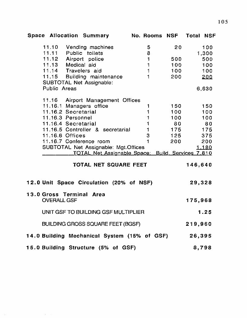
105
Space Allocation Summary No. Rooms NSF Total NSF
SUBTOTAL Net Assignable: Mgt.Offices
11.10 Vending machines 5 20 1 0011.11 Public to ile ts 8 1,30011.12 A irpo rt po lice 1 500 50011.13 Medical aid 1 1 00 1 0011.14 Travelers aid 1 100 10011.15 Building maintenance 1 200 200SUBTOTAL Net Assignable:Public Areas 6 ,6 30
11.16 A irport Management Offices11.16.1 Managers office 1 1 50 1 5011.16.2 S e c re ta r ia l 1 1 00 1 0011.16.3 Personnel 1 1 00 10011.16.4 S e c re ta r ia l 1 80 8011.16.5 C ontro lle r & secretaria l 1 175 17511.16.6 O ffic e s 3 125 37511.16.7 Conference room 1 200 200
1 .180TOTAL Net Assignable Space: Build. Services 7 .8 10
TOTAL NET SQUARE FEET 1 4 6 ,6 4 0
1 2 .0 Unit Space Circulation (20% of NSF)
1 3 .0 Gross Terminal AreaOVERALL GSF
UNIT GSF TO BUILDING GSF MULTIPLIER
BUILDING GROSS SQUARE FEET (BGSF)
1 4 .0 Building Mechanical System (15% of GSF)
1 5 .0 Building Structure (5% of GSF)
2 9 ,3 2 8
1 7 5 ,9 6 8
1.25
2 1 9 ,9 6 0
2 6 ,3 9 5
8 ,7 9 8

106
A .3 Terminal Space Requirements
G enera l D escrip tion/Function
Components of the term inal area complex include the term inal
building, gate positions, and apron area. This section provides
guidance on spatial requirements for functions carried out in the
proposed airport term inal building. These projected requirements
are provided to meet the needs of the community through the
planning period. This guidance is indicative of the design of airports
to accommodate international scheduled passenger operations.
The requirements for various term inal complex functional areas
were performed with the guidance of a Federal Aviation
Adm inistration Advisory C ircular 150/5360-13, Planning and Design
Guidelines for A irport Terminal Facilities. This document was used
along with the three case studies of Reno, Sacramento, and Tucson
International A irports with respect to the ir spatial requirem ents
(chapter five). The Airports were used to prepare estimates of
various term inal building space requirements, due to their sim ilar
enplanem ent levels to the adjacent international airports around
Palestine. Again, the projected enplanement level of Jerusalem
Airport is approximated to be one million enplaned passenger per
year.
The Terminal Building Space Requirements were developed for the
fo llow ing functional areas:
1.0 A irline gates
2.0 Public Lobby Areas
3.0 A irline T icke t C ounter/O ffices
4.0 Outbound Baggage Facilities

107
5.0 Public Corridors
6.0 Federal Inspection Services Facilities
7.0 Departure Lounges
8.0 Baggage Claim Facilities
9.0 A irline Operation Areas
10.0 Food and Beverage Services
11.0 Concessionaire and Building Services
12.0 Gross Terminal Area
1 .0 Airline Gates 16The proposed International Airport for the emerging country of Palestine at Jerusalem will have 16 aircraft parking positions on the terminal concourses. Among five major airlines the gates are used. Two hub airlines are suggested: one for Palestine airways and the other for Israel. In addition, domestic and commuter airlines share space at a separate term inal adjacent to the proposed terminal.
2 .0 Public Lobby Areas 53,200 s.f.General Description/Function Lobbies provide public circulation and access for carrying out the following functions: passenger ticketing; passenger and visitor waiting; concession areas and other passenger services; and baggage claim.
2.1 Ticketing Lobby/Circulation 10,500 s.f.The ticketing lobby should be arranged so that the enplaning passenger have immediate access and clear visibility to the individual airline ticket counters upon entering the building.Circulation patterns should allow passengers to by passticket counters with minimum interference. Seating for this area should be minimal to avoid congestion and to encourage passengers to proceed to the gate area. The sizing of a ticket lobby is a function of total length of airline counter.
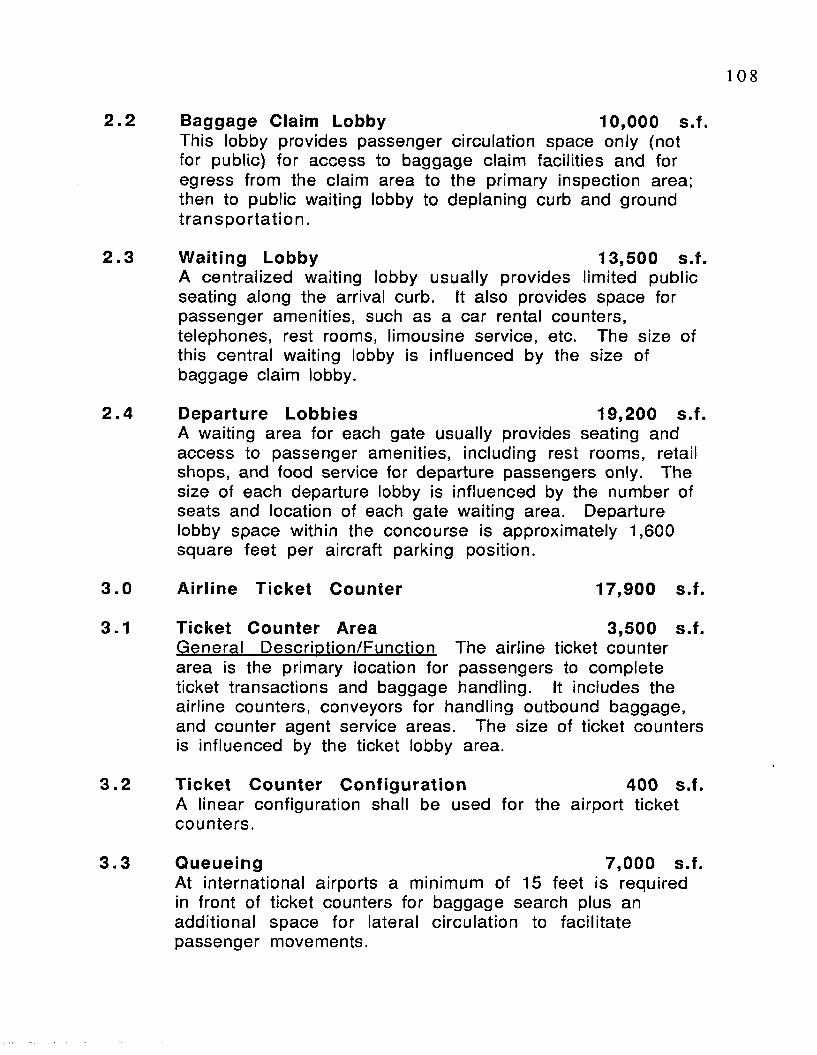
108
2 .2 Baggage Claim Lobby 10,000 s.f.This lobby provides passenger circulation space only (not for public) for access to baggage claim facilities and for egress from the claim area to the primary inspection area; then to public waiting lobby to deplaning curb and ground tra n sp o rta tio n .
2 .3 Waiting Lobby 13,500 s.f.A centralized waiting lobby usually provides lim ited public seating along the arrival curb. It also provides space for passenger amenities, such as a car rental counters, telephones, rest rooms, limousine service, etc. The size of this central waiting lobby is influenced by the size of baggage claim lobby.
2 .4 Departure Lobbies 19,200 s.f.A waiting area for each gate usually provides seating and access to passenger amenities, including rest rooms, retail shops, and food service for departure passengers only. The size of each departure lobby is influenced by the number of seats and location of each gate waiting area. Departure lobby space within the concourse is approximately 1,600 square feet per aircraft parking position.
3.0 Airline Ticket Counter 17,900 s.f.
3.1 Ticket Counter Area 3,500 s.f.General Descrip tion/Function The airline ticket counter area is the primary location for passengers to complete ticket transactions and baggage handling. It includes the airline counters, conveyors for handling outbound baggage, and counter agent service areas. The size of ticket counters is influenced by the ticket lobby area.
3 .2 Ticket Counter Configuration 400 s.f.A linear configuration shall be used for the airport ticket counters.
3 .3 Queueing 7,000 s.f.At international airports a minimum of 15 feet is required in front of ticket counters for baggage search plus an additional space for lateral c ircu la tion to facilita te passenger movements.

109
3 .4 Airline Ticketing Office Support 7,000 s.f.(behind ticket counter) 20x350General Descrip tion/Function The airline ticket counter office provides space.for a number of airline support activities. These activities include: accounting, safekeeping, training, and personnel areas.R e la tionsh ips The support office area sits between the ticket counters and the departing baggage sorting area and must have direct access to both. Access to this office must be controlled to the public, but it should be accessible to crew members.The area is about 1,200 s.f. for each of the proposed airlines. It may increase for the two hub airlines as needed. The following spaces should be provided for hub airlines only.
3.4.1 Supervisory Office (10x15) 150 s.f.The supervisor of this office support area is responsible for the outbound baggage area. It should have a clear view from the office for observation of the work area, and be accessible to crew members.
3 .4 .2 Accounting Office 150 s.f.The primary function of this area is to handle office paper work and bookkeeping. It should be adjacent to the superv isor’s office.
3 .4 .3 Check Out Area 200 s.f.This area should be convenient and restricted to authorized staff only. It should be located near the work space with a direct access.
3.4 .4 Locker/Lounge Area 200 s.f.This room provides a space for personal needs and break area for the staff needs
3.4 .5 Personnel Office
3 .4 .6 Training
3 .4 .7 Rest rooms (Women & Men)
100 s.f.
150 s.f.
200 s.f.

1 1 0
3 .3 .8 Storage 100 s.f.This area provides storage for office supplies, and should open onto the work area.
4 .0 Outbound Baggage Facilities
4.1 All Airlines 12,250 s.f.General Description/Function The outbound baggage facility is where baggage is received by mechanical conveyors from ticket counters. The principal purpose is for baggage sorting, and loading baggage into containers or carts for delivery to the aircraft. A special area shall be provided for skis, oversize parcels, and other objects that will need special handling.R e la tionsh ips This area must be visible and immediately accessible from the ticketing support office and ticket counter areas. It should also open onto the apron area with direct access for loading.
5 .0 Enplaned & Deplaned Passenger Corridors.General Description/Function Corridors must be provided for passenger circulation between aircraft boarding gates and various departure lobbies. Separate corridors must be provided for enplaned and deplaned passengers. Corridors for deplaning must direct passengers to a separate holding area for Federal Inspection Services.
6.0 Federal Inspection Service Facilities 9,515 s.f.G eneral D escrip tion/Function Airports with international traffic require space for Federal Inspections (Immigration, Custom, Agriculture, and Public Health Service) of passengers, aircraft, crew members, baggage, and cargo. Itis a governmental control point for passengers, baggage, andcargo inspection and control public access to parked a irc ra f t .R elationships This area should be adjacent to baggage claim, and access to this area must be controlled ( re s tr ic te d ).
6.1 Immigration and Naturalization Services 3,815 s.f.General Description/Function The purpose of this area is to examine all passengers arriving in Palestine to determ ine their adm issibility under the provisions of the Immigration

1 1 1
and Nationality act.R e la tionsh ips This service area shall be adjacent to baggage claim and accessible to the secondary inspection area.
6.1.1 Number of Primary Inspection Booths 7
6 .1 .2 Genera! Office Space 1,500 s.f.The primary function of this space is to accommodate inspectors when not at their assigned inspection counters. The minimum is one desk space per primary inspection booth and secondary position.
6.1 .3 Conference Training Room 200 s.f.A conference training room should be provided for meetings and the training of inspection personnel
6 .1 .4 Break/Lunch Room 200 s.f.Adjacent to passenger processing area, provided for inspection personnel.
6.1 .5 Secondary Inspection Area 250 s.f.Secondary inspection counters.
6.1 .6 Interview Room(s) 80 s.f.An interviewing room and a waiting area is required.
6.1 .7 Supervisor’s Office 150 s.f.The supervisor’s office requires a clear glassed wall toview the primary inspection area, a direct access to the reception space.
6 .1 .8 Director’s Office 200 s.f.The reception should be located immediately adjacent to the director’s office entry. The director frequently meets with passengers in the conference room.
6 .1 .9 C lerk/Reception 160 s.f.Adjacent to Supervisor’s with immediate access to d ire c to r’s offices.
6 .1 .10 Employee Toilets 300 s.f.Men’s and Women’s (2 @ 150 s.f. each)Private toilets are required for employees and should not be
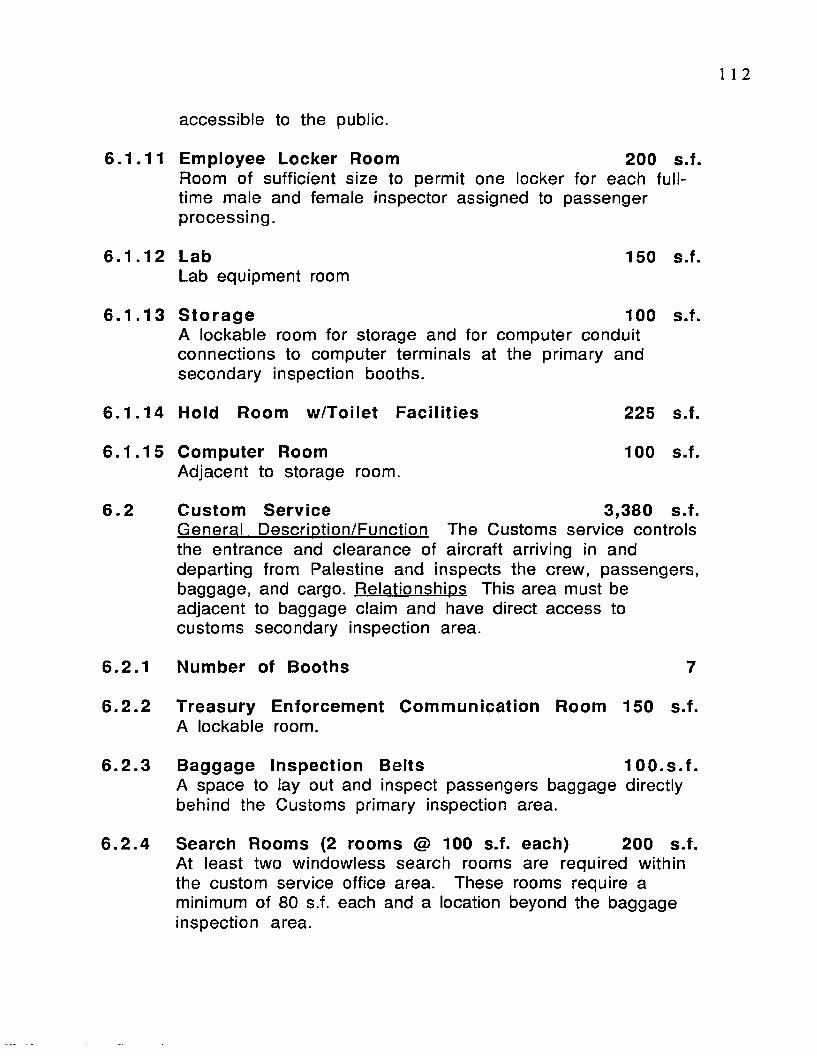
1 1 2
accessible to the public.
6.1.11 Employee Locker Room 200 s.f.Room of sufficient size to permit one locker for each fu lltime male and female inspector assigned to passenger processing.
6.1 .12 Lab 150 s.f.Lab equipment room
6 .1 .13 Storage 100 s.f.A lockable room for storage and for computer conduit connections to computer terminals at the primary and secondary inspection booths.
6 .1 .14 Hold Room w/Toilet Facilities 225 s.f.
6 .1 .15 Computer Room 100 s.f.Adjacent to storage room.
6 .2 Custom Service 3,380 s.f.General Description/Function The Customs service controls the entrance and clearance of aircraft arriving in and departing from Palestine and inspects the crew, passengers, baggage, and cargo. Relationships This area must be adjacent to baggage claim and have direct access to customs secondary inspection area.
6.2.1 Number of Booths 7
6.2.2 Treasury Enforcement Communication Room 150 s.f.A lockable room.
6.2.3 Baggage Inspection Belts 100 .s.f.A space to lay out and inspect passengers baggage directly behind the Customs primary inspection area.
6.2 .4 Search Rooms (2 rooms @ 1 0 0 s.f. each) 200 s.f.At least two windowless search rooms are required within the custom service office area. These rooms require a minimum of 80 s.f. each and a location beyond the baggage inspection area.
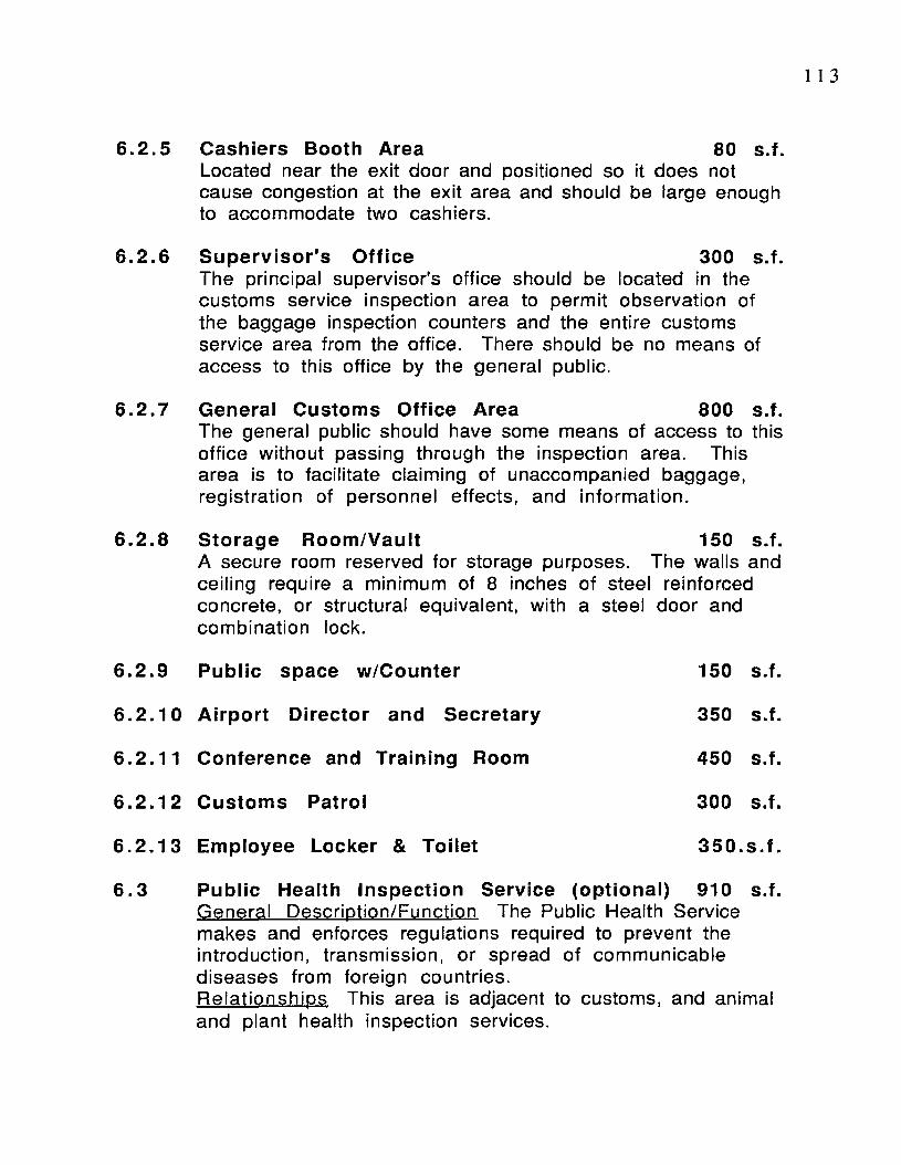
1 1 3
6.2 .5 Cashiers Booth Area 80 s.f.Located near the exit door and positioned so it does notcause congestion at the exit area and should be large enough to accommodate two cashiers.
6 .2 .6 Supervisor's Office 300 s.f.The principal supervisor's office should be located in the customs service inspection area to perm it observation of the baggage inspection counters and the entire customs service area from the office. There should be no means of access to this office by the general public.
6.2 .7 General Customs Office Area 800 s.f.The general public should have some means of access to this office without passing through the inspection area. This area is to facilitate claiming of unaccompanied baggage, registration of personnel effects, and information.
6.2.8 Storage Room/VaultA secure room reserved for storage purposes, ceiling require a minimum of 8 inches of steel concrete, or structural equivalent, with a steel com bination lock.
150 s.f.The walls and
reinforced door and
6.2.9 Public space w/Counter 150 s.f.
6 .2 .10 Airport Director and Secretary 350 s.f.
6 .2.11 Conference and Training Room 450 s.f.
6 .2 .12 Customs Patrol 300 s.f.
6 .2 .13 Employee Locker & Toilet 350. s.f.
6 .3 Public Health Inspection Service (optional) 910 s.f.General Description/Function The Public Health Service makes and enforces regulations required to prevent the introduction, transmission, or spread of communicable diseases from foreign countries.R e la tionsh ips This area is adjacent to customs, and animal and plant health inspection services.
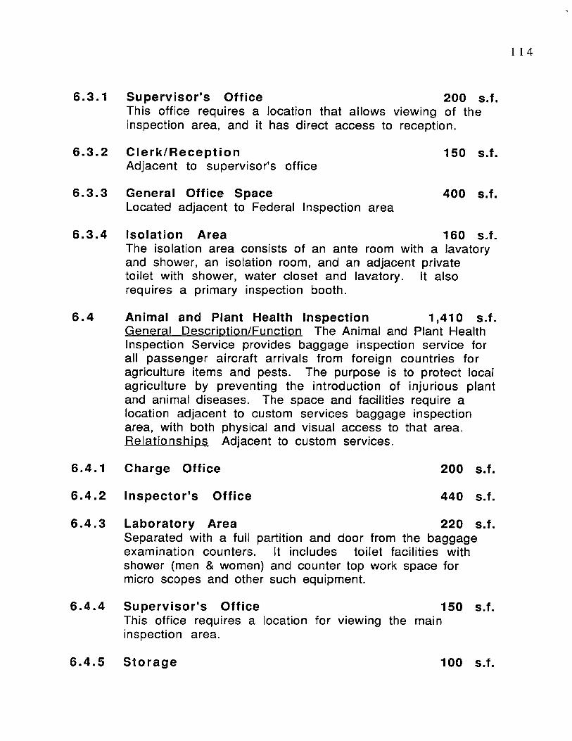
1 14
6.3.1 Supervisor's Office 200 s.f.This office requires a location that allows viewing of the inspection area, and it has direct access to reception.
6 .3 .2 Clerk/Reception 150 s.f.Adjacent to supervisor’s office
6 .3 .3 General Office Space 400 s.f.Located adjacent to Federal Inspection area
6.3 .4 Isolation Area 160 s.f.The isolation area consists of an ante room with a lavatory and shower, an isolation room, and an adjacent private toilet with shower, water closet and lavatory. It alsorequires a primary inspection booth.
6.4 Animal and Plant Health Inspection 1,410 s.f.General Description/Function The Animal and Plant Health Inspection Service provides baggage inspection service for all passenger a ircraft arrivals from foreign countries for agriculture items and pests. The purpose is to protect localagriculture by preventing the introduction of in jurious plantand animal diseases. The space and facilities require a location adjacent to custom services baggage inspection area, with both physical and visual access to that area.R e la tionsh ips Adjacent to custom services.
6.4.1 Charge Office 200 s.f.
6 .4 .2 Inspector's Office 440 s.f.
6 .4 .3 Laboratory Area 220 s.f.Separated with a full partition and door from the baggage examination counters. It includes to ilet facilities with shower (men & women) and counter top work space formicro scopes and other such equipment.
6 .4 .4 Supervisor's Office 150 s.f.This office requires a location for viewing the main inspection area.
6.4 .5 Storage 100 s.f.
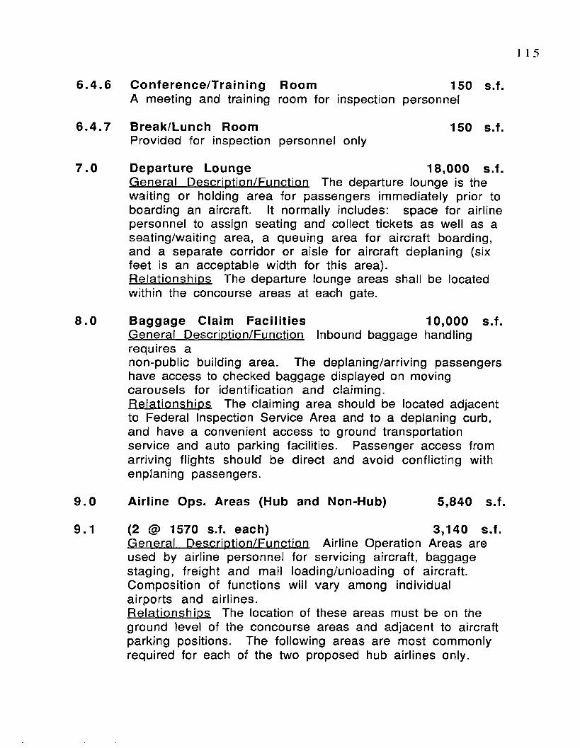
1 I 5
6.4 .6 Conference/Training Room 150 s.f.A meeting and training room for inspection personnel
6.4.7 Break/Lunch Room 150 s.f.Provided for inspection personnel only
7 .0 Departure Lounge 18,000 s.f.General Description/Function The departure lounge is the waiting or holding area for passengers immediately prior to boarding an aircraft. It normally includes: space for airlinepersonnel to assign seating and collect tickets as well as a seating/waiting area, a queuing area for aircraft boarding, and a separate corridor or aisle for aircraft deplaning (six feet is an acceptable width for this area).Rela tionships The departure lounge areas shall be located within the concourse areas at each gate.
8 .0 Baggage Claim Facilities 10,000 s.f.General Description/Function Inbound baggage handling requires anon-public building area. The deplaning/arriving passengers have access to checked baggage displayed on moving carousels for identification and claim ing.R ela tionships The claiming area should be located adjacent to Federal Inspection Service Area and to a deplaning curb, and have a convenient access to ground transportation service and auto parking facilities. Passenger access from arriving flights should be direct and avoid conflicting with enplaning passengers.
9.0 Airline Ops. Areas (Hub and Non-Hub) 5,840 s.f.
9.1 (2 @ 1570 s.f. each) 3,140 s.f.General Description/Function Airline Operation Areas are used by airline personnel for servicing aircraft, baggage staging, freight and mail loading/unloading of aircraft. Composition of functions will vary among individual airports and airlines.R ela tionships The location of these areas must be on the ground level of the concourse areas and adjacent to aircraft parking positions. The following areas are most commonly required for each of the two proposed hub airlines only.
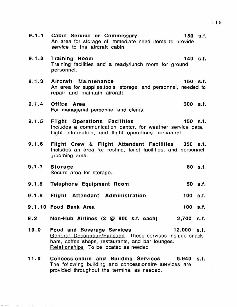
1 1 6
9.1.1 Cabin Service or Commissary 150 s.f.An area for storage of immediate need items to provide service to the aircraft cabin.
9 .1 .2 Training Room 140 s.f.Training facilities and a ready/lunch room for ground personnel.
9 .1 .3 Aircraft Maintenance 150 s.f.An area for supplies,tools, storage, and personnel, needed to repair and maintain aircraft.
9 .1 .4 Office Area 300 s.f.For managerial personnel and clerks.
9 .1 .5 Flight Operations Facilities 150 s.f.Includes a communication center, for weather service data, fligh t information, and fligh t operations personnel.
9 .1 .6 Flight Crew & Flight Attendant Facilities 350 s.f.Includes an area for resting, toilet facilities, and personnelgrooming area.
9 .1 .7 StorageSecure area for storage.
80 s.f.
9 .1 .8 Telephone Equipment Room 50 S.f.
9 .1 .9 Flight Attendant Administration 100 s.f.
9 .1 .1 0 Food Bank Area 100 s.f.
9 .2 Non-Hub Airlines (3 @ 900 s.f. each) 2,700 s.f.
1 0 .0 Food and Beverage Services 12,000 s.f.General Description/Function These services include snack bars, coffee shops, restaurants, and bar lounges. Relationships To be located as needed
11 .0 Concessionaire and Building Services 5,940 s.f.The following building and concessionaire services are provided throughout the terminal as needed.

1.1 News and Tobacco (3) 600
1.2 Gift shop (3) 1800
1.3 Drug Store 600Including sale of books, cards, and liquor.
1.4 Auto Rental Counters (4) 500
1.5 Displays 90Including courtesy phones
1.6 Insurance 150Including counters and machines.
1.7 Public Lockers (2) 140
1.8 Public Telephones (10 Banks) 300
1.9 Automated Post Office 150
1 .10 Vending Machines (5) 100
1.11 Public Toilets (8 @ Men/Women) 1,300
1.12 Airport Police/Security Office 500
1.13 Medical Aid Facilities 100
1.14 Travelers Aid 100
1 .15 Building Maintenance and Storage 200
1.16 Airport management Offices (Total) 1,180
1.16.1 Manager’s Office 150
1 .16 .2 S ecretar ia l 100
1 .16 .3 Personnel Management 100
1 .16 .4 Secre ta r ia l 80
1 1 7
s.f.
s.f.
s.f.
s.f.
s.f.
s.f.
s.f.
s.f.
s.f.
s.f.
s.f.
s.f.
s.f.
s.f.
s.f.
s.f.
s.f.
s.f.
s f.
s.f.
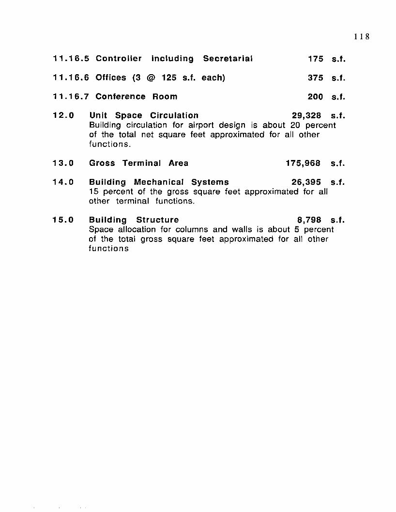
1 1 8
1 1 .1 6 .5 Controller including Secretarial 175 S.f.
11 .16 .6 Offices (3 <S> 125 s.f. each) 375 S.f.
11 .16 .7 Conference Room 200 s.f.
12 .0 Unit Space Circulation 29,328 s.f.Building circulation for airport design is about 20 percent of the total net square feet approximated for all other func tions .
13.0 Gross Terminal Area 175,968 s.f.
14 .0 Building Mechanical Systems 26,395 s.f.15 percent of the gross square feet approximated for all other term inal functions.
15.0 Building Structure 8,798 s.f.Space allocation for columns and walls is about 5 percent of the total gross square feet approximated for all other fu n c tio n s
1 1 9
A .4 Proposed Terminal Design

J E R U S A L E M I N T E R N A T I O N A LODEH S. KHEIR MASTER OF ARCHITECTURE MAY 1993


ENTRANCE LOBBY

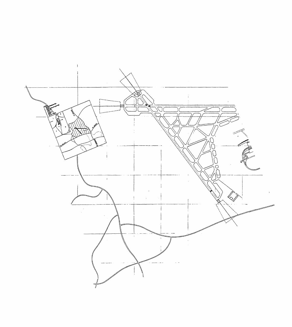
aiz^ 'O oc


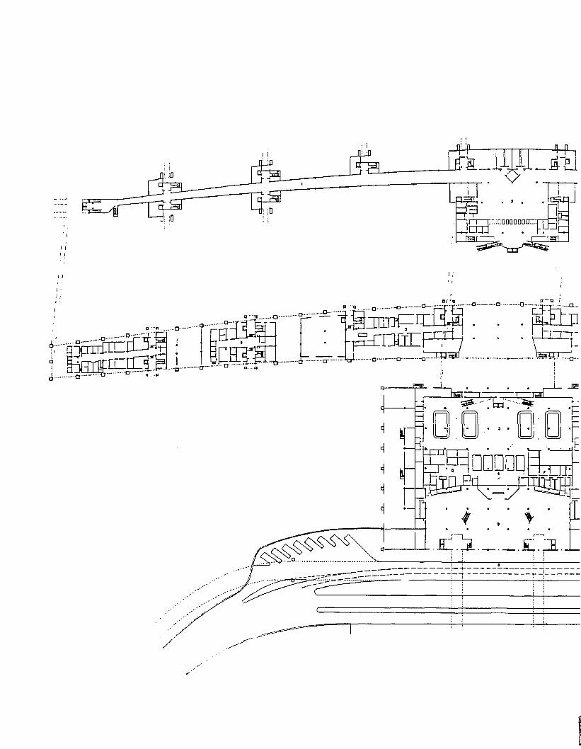
i-.. ^p xn u J


~o-a....• • • o .
O"
• NMVti CUV
1

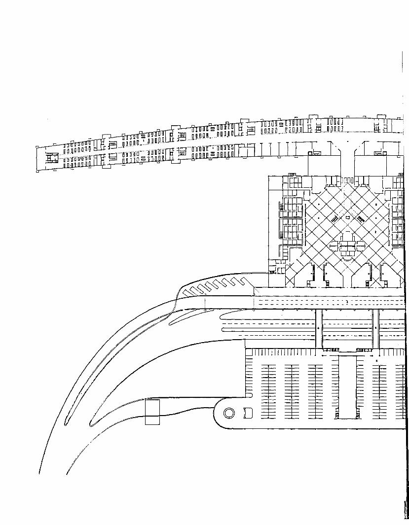
' • 11 i ll l \
tn m


E l . . . . ® i i . i i . , ________ i 3 _
&
3 l* b L _ P <
i \ jinn I l l l m l l l l i l U
DEPARTURE LEVEL
l£G0t>1 M X X H ttW I IDKTM ) t D W n M O M * . UVtnOMOGI I M K M t n u n M
^999

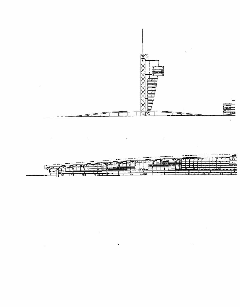
m nmrnn


n n
jim. JLQLT__TT
coN canse section


I

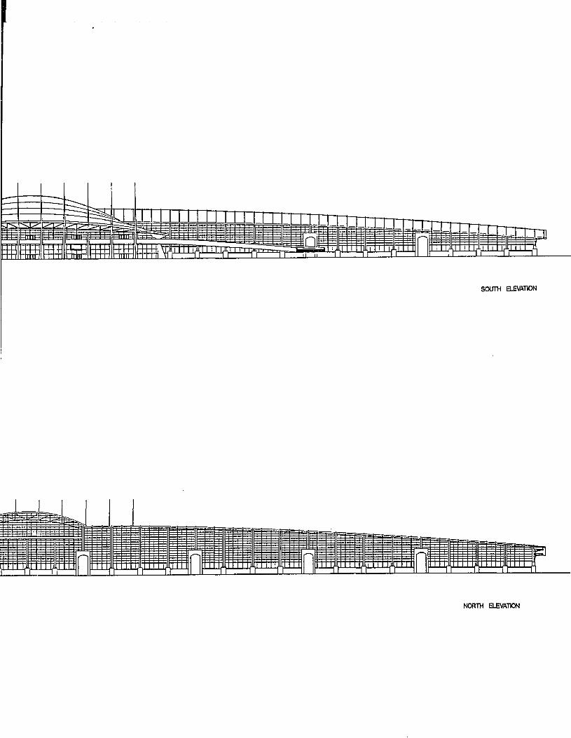
SOUTH ELEVATION
NORTH ELEVATION

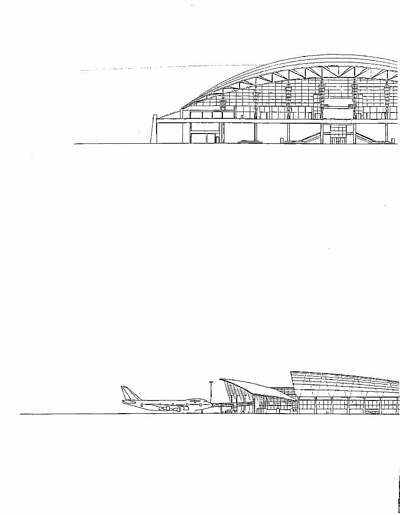
—h- ■ U '
l.. I F O F Ir


ELEVATION


127
APPENDIX B
SUMMARIES OF ENPLANED PASSENGERS AND
AIRCRAFT DEPARTURES AT SMALL, MEDIUM,
AND LARGE AIRTRAFFIC HUBS IN
THE U.S., 1990

Table B.1 Small Air Traffic Hubs 128
Summary of Enplaned Passengers, and Aircraft Departures. All Services at Small Air Traffic Hubs, 1990
Community (Airport Name)
Enplaned Passengers
Total Performed
Aircraf tDeparturesScheduled
Rhode Island (Theodore Francis Green St.) 1060719 16890
Alabama (Birmingham Muni) 1001983 201 12
Nebraska, Omaha (Eppley Airfield) 994132 19952
Florida (Sarasota-Bradenton) 989935 15765
Hawaii, Kailua-Kona (Ke-Ahole) 977274 14800
Arkansas, Little Rock (Adams Fid.) 950540 15154
Kentucky, Louisville (Standiford Fid.) 937645 21813
N.C. (Greensboro-High PT-Winstn Reg.) 894532 2351 9
New York (Albany County) 878372 15007
Virginia (Richard E Byrd Flying Fid.) 864381 2 04 43
Guam, Guam (Agana Fid.) 770549 695 2
Washington (Spokane Intl.) 747329 253 15
Cal. (Long Beach) 692995 14443
Iowa (Des Moines Muni) 658619 12144
Hawaii, Hilo (General Lyman Fid.) 651191 10868
South Carolina (Charleston AFB/MUNI) 6 31 956 14215
Michigan.Grand Rapids (Kent County) 614280 13086
Texas (Lubbock Regional) 6 11413 11574
Texas, Midland/Odessa (Midland Regional) 5 80905 8675
Kansas, Wichita (Mid-Continent) 561432 13772
Source: U .S .D.O .T., 1990, Airport Activity Statistics of Certificated Air Carriers, FAA

Table B.1 Small Air Traffic Hubs 129
Colorado, Colorado Spring (Peterson Fid.) 551507 10903
Texas (Harlingen Industrial Airpark) 529042 7444
Idaho (Boise Air Terminal/Gowen Fid.) 525092 16802
Georgia (Savannah Intl.) 520881 1 1089
South Carolina (Columbia Metropolitan) 5 12 759 13531
S.C. (Greenville/Spartanburg) 503271 1 1580
Florida (Daytona Beach Regional) 490 336 7514
Tennessee,Knoxville (Me Ghee Tyson) 477768 10228
Maine (Portland Intl. Jetport) 472393 871 2
PA. (Harrisburg Intl.) 437341 10537
Texas (Amarillo Air Terminal) 43 5 2 9 7 661 6
Wisconsin, Madison (Truax Fid.) 425563 8926
Louisiana, Baton Rouge (Ryan) 423808 8837
Texas (Corpus Christi Intl.) 423498 6651
New York, Islip (Long Island-Macarthur) 422400 7001
Florida (Pensacola Regional) 394222 8765
Cat. (Fresno Air Terminal) 393442 208 79
Miss. (Allen C Thompson Fid.) 3 91018 9001
Florida (Tallahassee Muni.) 381840 9193
Alabama, Huntsville (Madison County) 381668 9880
Miss., Al/Pascagoula (Bates Fid.) 380798 9734
Michigan (Detroit City) 3 62 655 6828
Florida, Melbourne (Cape Kennedy Reg.) 360126 5 83 8
VI. (Harry S. Truman) 3 57 133 6957
Source: U .S.D.O.T., 1990, Airport Activity Statistics of Certificated Air Carriers, FAA

Table B.1 Small Air Traffic Hubs 1 3 0
Cal., Indio (Palm Springs Muni) 3 5 3 2 9 4 9 2 7 0
PA. (Allentown-Bethlehem-Easton) 3 4 9 3 5 8 774 4
Iowa (Cedar Rapids Muni) 3 4 1 1 4 2 7 7 5 3
Vermont (Burlington Intl.) 3 0 6 4 8 9 7 5 0 5
Kentucky,Lexington (Blue Grass) 2 9 1 6 3 4 781 1
Mariana Islands (Saipan Intl.) 2 7 9 0 1 9 4 0 3 7
N. Hampshire, Manchester (Muni) 2 6 7 9 6 3 63 4 4
Louisiana (Shreveport Regional) 2 5 7 2 2 9 7 6 5 6
Indiana (Municipal/Baer Fid.) 2 4 2 0 0 0 7851
Tennessee, Chattanooga (Lovell Field) 2 3 9 7 4 6 5 3 2 7
Montana, Billings (Logan Field) 2 3 7 6 9 9 8741
Alaska (Fairbanks Intl.) 2 3 3 8 0 9 6 1 5 0
Ohio (Akron-Canton) 2 3 0 2 4 9 5 6 0 6
Cal. (Santa Barbara) 2 2 6 4 7 2 9 9 9 9
S.D., Sioux Falls (Joe Foss Fid.) 2 2 6 4 3 6 6 4 6 6
Oregon. Eugene (Mahlon Sweet Fid.) 2 2 4 6 5 8 80 7 4
Virginia (Roanoke Muni) 2 2 4 5 9 5 7 1 4 3
Indiana, Suuth Bend (Michiana Regional) 2 2 4 0 5 0 6 6 3 0
Illinois, Moline (Quad-City) 2 2 0 0 9 3 6 2 8 6
Mich., Saginaw/Bay City/Midland (Tri Cit 2 1 9 3 1 0 3 9 5 2
Cal., San Francisco (Buchana Field) 4 9 5 3 2 128 6
Texas, Houston (Ellington Field) 18 9 6 7 1188
Cal. (Santa Maria Public) 62 1 3 1740
Over-A ll Total, Sm all Hubs 3 1 8 9 3 9 9 7 6 9 2 5 0 4
Source: U .S .D .O .T., 1990, Airport Activity Statistics of Certificated Air Carriers, FAA

Table B-2 Medium Air Traffic Hubs
Summary of Enplaned Passengers, and Aircraft Departures. All Services at Medium Air Traffic Hubs, 1990
Community (Airport Name)
Enplaned Passengers
Total Performed
Aircraf tDeparturesScheduled
North Carolina (Raleigh-Durham) 436 5 3 4 5 6621 1
Ohio (Greater Cincinnati) 390 7 6 2 5 65533
Tennessee (Memphis Intl.) 388 7 2 0 8 94420
Ohio, Cleveland (Hopkins Intl.) 3 83 6 0 5 0 76988
Puerto Rico (Luis Munoz Marin Intl.) 3 61 8 0 9 0 39208
Tennessee, Nashville (Metropolitan) 3 4 0 4 2 4 3 57474
Louisiana, New Orleans (Intl./Moisant) 3 3 6 1 0 6 2 49121
Missouri, Kansas City (Intl.) 3 35 8 1 1 6 52781
Cal. (San Jose Muni) 312 8 3 9 3 4 91 73
Oregon (Portland Intl.) 302 5 3 4 5 69578
Texas, Dallas (Love Field) 288 2836 39481
Cal. (Oakland Metropolitan Intl.) 267 0788 45986
Cal. (Ontario Intl.) 2 64 0734 409 25
Florida (Palm Beach Intl.) 2 60 9138 29363
Indiana (Indianapolis Intl.) 2 60 1839 53471
Texas (San Antonio Intl.) 259 3896 39740
New Mexico (Albuquerque Intl.) 238 4 6 4 7 341 38
Cincinnati (Bradley Intl.) 231 2 4 5 5 31850
Cal. (Orange County) 220 3700 3 72 75
Hawaii (Kahului) 209 4390 29624
Source: U .S .D .O .T., 1990, Airport Activity Statistics of Certificated Air Carriers, FAA

Table B-2 Medium Air Traffic Hubs 13 2
Texas, Austin (Robert Mueller Muni) 2 05 4955 31494
Wisconsin, Milwaukee (Mitchell Field) 1915390 39724
Ohio (James M COX/Dayton Intl.) 1845160 369 66
Cal. (Sacramento Metropolitan) 1737096 397 23
Florida, Fort Myers (Southwest) 1712679 22210
Cal. (Hollywood-Burbank) 1698739 30444
Ohio (Port Columbus Intl.) 1685100 29986
Texas (El Paso Intl.) 1673243 283 33
New York (Greater Buffalo Intl.) 1637293 30554
Oaklahoma (Will Rogers Intl.) 1519518 253 47
Oklahoma (Tulsa Intl.) 1483037 24975
Alaska (Anchorage Intl.) 136 2282 35891
Nevada (Reno Intl.) 1343619 21609
Florida (Jacksonville Intl.) 126 6677 24585
Hawaii (Lihue) 1264738 18704
Arizona (Tucson inti.) 1263509 20201
Va. (Norfolk Regional) 1254846 264 95
New York, Syracuse (Clarence E HancooK 1166598 29514
New York (Rochester-Monroe County) 1154747 25132
Over-All Total, Medium Hubs 8 9 9 2 5 1 2 6 1 5 4 4 2 2 7
Source: U .S.D .O .T., 1990, Airport Activity Statistics of Certificated Air Carriers, FAA

Table B-3 Large Air Traffic Hubs 133
Summary of Enplaned Passengers, and Aircraft Departures. All Services at Large Air Traffic Hubs, 1990
Community Enplaned Aircraf t(Airport Name) Passengers
Total PerformedDepartureScheduled
Illinois, Chicago (O'hare Intl.) 256 3638 3 3 2 2 4 3 0
Texas (Dallas/FT.Worth Intl.) 2 2 8 9926 7 2 6 6 7 3 7
Georgia, Atlanta (Hartsfield Intl.) 226 6566 5 2 8 5 6 9 3
Cal. (Los Angeles Intl.) 18438056 21 3 3 0 2
Arizona (Phoenix Sky Harbor Intl.) 10727494 1 48342
New York (La Guardia) 10725465 129670
Michigan, Detroit (Wayne County) 9 90 3078 134929
New Jersey (Newark) 9 85 3925 130286
New York (John Kennedy Intl.) 9687068 7 4 6 5 9
Massachusetts, Boston (Logan Intl.) 954 9585 114153
Missouri (Lambert-ST Louis Muni) 9332091 1 35089
Florida (Miami Intl.) 9226103 106858
Hawaii (Honolulu Intl.) 9002217 926 59
Minnesota (Minneapolis-St Intl.) 8837228 114872
PA, Pittsburgh (Greater Pittsburgh) 7 912394 1 25 276
Nevada, Las Vegas (McCarran Intl.) 7796218 921 96
Florida (Orlando Intl.) 767 7769 8 4 9 2 4
Texas (Houston Intl.) 754 3899 104 249
Washington (Seattle-Tacoma Intl.) 7385594 122 226
North Carolina, Charlotte (Douglas Muni) 7 07 6954 120 210
Source: U .S .D .O .T ., 1990, Airport Activity Statistics of Certificated Air Carriers, FAA

Table B-3 Large Air Traffic Hubs
Washington, D.C. (Washington Nat.) 7034693 9 7 0 4 3
PA, Philadelphia (Intl.) 6970820 105830
Utah (Salt Lake City Intl.) 538 8178 77368
Cal. (San Diego Intl. Linbergh) 526 0 9 0 7 70156
Florida (Tampa Intl.) 478 1 0 2 0 64396
Washington, D.C. (Dulles inti.) 444 8592 80651
Maryland (Balto/Wash Intl.) 4 42 0425 733 00
Texas (William P Hobby) 39 7 2 3 2 7 6 1 3 8 7
Florida (FT. Launderdale Intl.) 387 5 3 5 7 4 6 5 8 4
Illinois, Chicago (Midway) 354 7040 64465
Over-All Total, Large Hubs 3 0 7 0 1 2 5 8 0 3 9 8 6 0 1 4
Source: U .S .D .O .T ., 1990, Airport Activity Statistics of Certificated Air Carriers, FAA
Top Related