


![BC620 SAP Idoc Interface Technology[1]](https://static.fdocuments.us/doc/165x107/552ded884a795956618b47ad/bc620-sap-idoc-interface-technology1.jpg)


Languages
Pages
Legal


1
Fabrication of Quarter-size ScintillatingStrip Muon Detector Planes
Mitch WayneUniversity of Notre Dame
2
Motivation
Fabrication of quarter-size planes (1.4m × 2.8m) will exercise all the steps required to make full-sized planesDevelop techniques: splicing, routing, calibration, etc.Provides a benchmark for future development:
• New photodetectors - APDs, VLPCs, etc• New scintillator and/or waveshifting materials
Conserves raw materials – scintillating strips and fiber
3
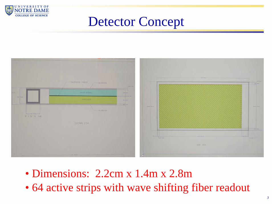
Detector Concept
• Dimensions: 2.2cm x 1.4m x 2.8m• 64 active strips with wave shifting fiber readout
4
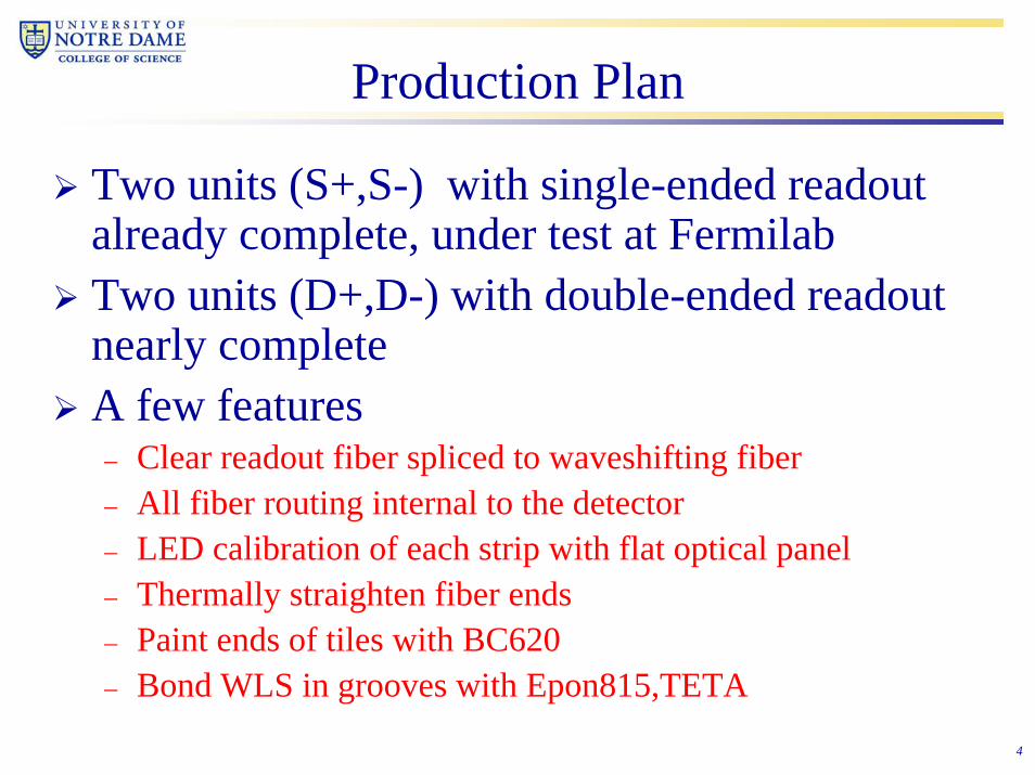
Production Plan
Two units (S+,S-) with single-ended readout already complete, under test at FermilabTwo units (D+,D-) with double-ended readout nearly completeA few features– Clear readout fiber spliced to waveshifting fiber– All fiber routing internal to the detector– LED calibration of each strip with flat optical panel– Thermally straighten fiber ends– Paint ends of tiles with BC620– Bond WLS in grooves with Epon815,TETA
5
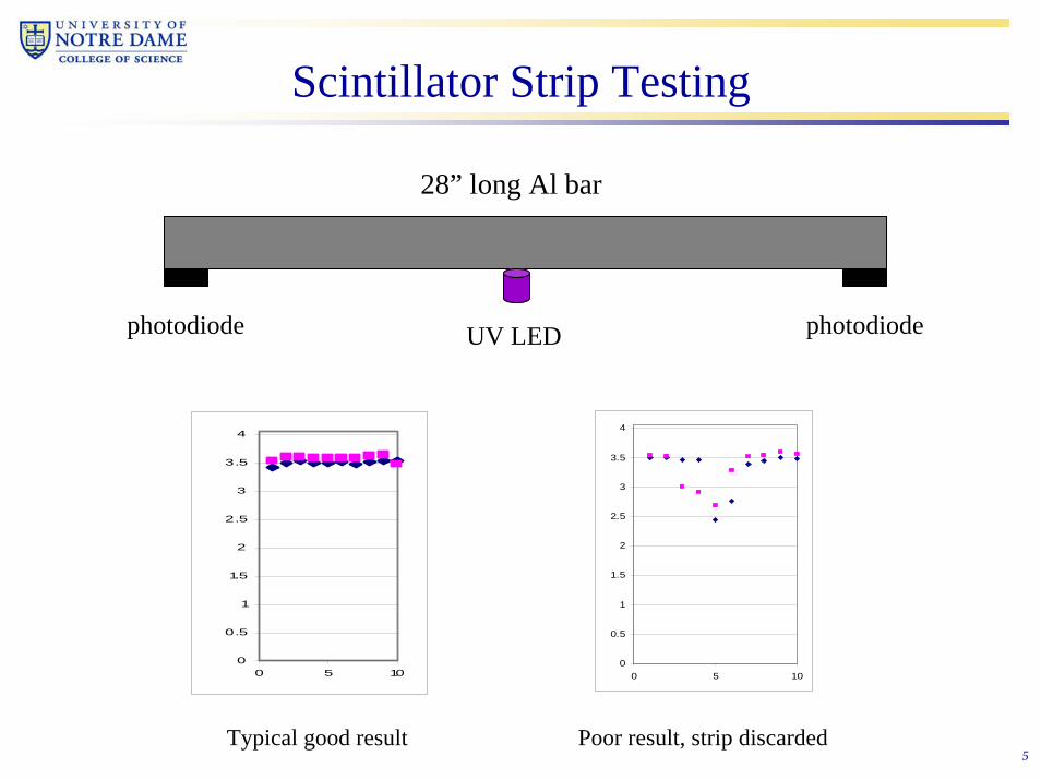
Scintillator Strip Testing
28” long Al bar
0
0.5
1
1.5
2
2.5
3
3.5
4
0 5 10
photodiode photodiodeUV LED
0
0.5
1
1.5
2
2.5
3
3.5
4
0 5 10
Typical good result Poor result, strip discarded

6
Fiber preparation
1.2mm Clear waveguide, spooled1.2mm Wavelength Shifter, spooled
Visual inspection with LED on end Measured on cutting templateA clean, razor cut is made with ‘HandiCutter’
All fiber, both clear and waveshiftingis characterized before and after splicing to assure quality

7
Fiber testing
Fibers characterized with respect to each otherAcceptance cut is 70% of average for groupLED, photodiode, water couplantThree test runs each
Digitization and readout
photodiode green LED

8
Light Test of Waveshifting Fiber for S+
0500
100015002000250030003500400045005000
0 10 20 30 40 50
Fiber number
Aver
age
valu
e
Normalized fiber averagesAverage
44 separate pieces - no rejected fiber
Sigma of ~ 10%

9
Thermal Splicing
Splicing machine (U. of Mississippi design) used at Fermilab lab 7

10
photodiode UV LED
LED Test of Single-ended Spliced Fibers
Al mirror
Splice covered by protective plastic sleeveDigitization
and readout
Transmission ofspliced fiber used for S+
0.0
500.0
1000.0
1500.0
2000.0
2500.0
3000.0
3500.0
4000.0
1 6 11 16 21 26 31 36 41 46 51 56 61
Fiber Number
Counts
proto1_S+

11
Comparison of Single, Doubled-ended Splices
Spliced Fiber Testsproto1 & 2 single splice; proto3 & 4 double splice
0
500
1000
1500
2000
2500
3000
3500
4000
4500
5000
1 3 5 7 9 11 13 15 17 19 21 23 25 27 29 31 33 35 37 39 41 43 45 47 49 51 53 55 57 59 61 63
proto1proto2proto3proto4
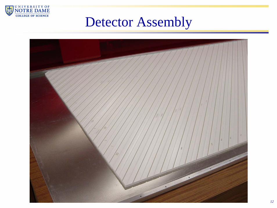
12
Detector Assembly

13
Detector Assembly (cont.)

14
Detector Assembly (cont.)

15
Detector Assembly (cont.)

16
Gluing of Clear Fiber to Cookie

17
Diamond Finishing of Fiber Cookie

18
Detector Ready to Close Up
19
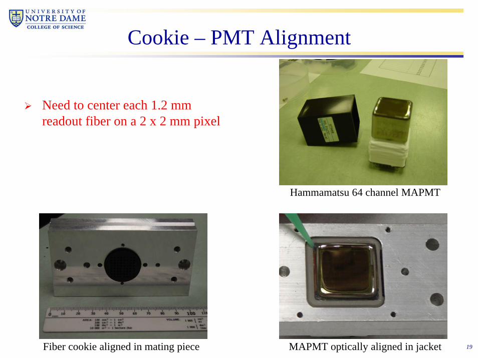
Cookie – PMT Alignment
Hammamatsu 64 channel MAPMT
Need to center each 1.2 mm readout fiber on a 2 x 2 mm pixel
Fiber cookie aligned in mating piece MAPMT optically aligned in jacket

20
LED Calibration
Uses “flat optical panels” to produce a fairly uniform ribbon of LED lightGreen Nichia LEDsEach panel covers 8 scintillator stripsEach panel monitored by pin diode
00.20.40.60.8
11.21.41.61.8
2
0 2 4 6 8 10 12 14
Results of light tests for 40 panels

21
LED Calibration – Flat Panel Location

22
Outreach
Much of the work done this summer under the Notre Dame QuarkNet programTalented, enthusiastic workforceNice connection with the cosmic ray “grid” programExcellent recruiting tool for future young physicists
The Team
Leroy Castle, Rich Eberly – HS teachers
Pat Kosciuk, Stan Strycker, Matt Weis – HS students
Mike McKenna - technician

23
Summary and Future OutlookTwo single-sided muon detectors are complete and under test at Fermilab (see talk of R. Abrams)Two double-sided detectors nearly complete, ready for deliver within a couple of weeksFabrication techniques well understood, some improvements on original design already in placeFuture plans:
– Fabricate another 4 quarter-size detectors for beam test– Tool up for fabrication of a full-size detector– Respond to ongoing cosmic ray measurements at Fermilab– Explore new, better materials and alternative photodetectors
Top Related