


Languages
Pages
Legal

Electrical Machines and Drives 4/1 Collection of Exercises
Darmstadt University of Technology Institute of Electrical Energy Conversion
Exercise 4.1: DC drive for foil stretching machine
A separately excited DC machine with converter feeding is used as a variable speed drive for a
foil stretching machine. The motor is cooled by an externally driven fan. Drive data:
P = (20 ... 200 ... 200) kW for n = (140 ... 1400 ... 2100) 1/min
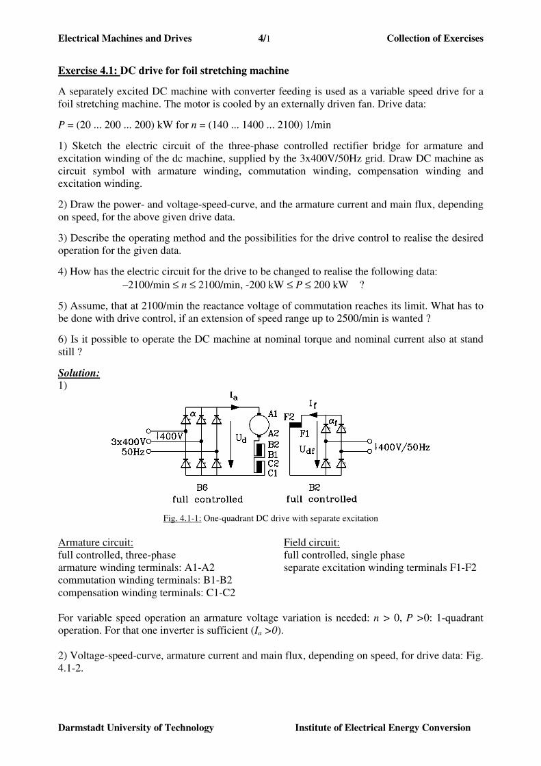
1) Sketch the electric circuit of the three-phase controlled rectifier bridge for armature and
excitation winding of the dc machine, supplied by the 3x400V/50Hz grid. Draw DC machine as
circuit symbol with armature winding, commutation winding, compensation winding and
excitation winding.
2) Draw the power- and voltage-speed-curve, and the armature current and main flux, depending
on speed, for the above given drive data.
3) Describe the operating method and the possibilities for the drive control to realise the desired
operation for the given data.
4) How has the electric circuit for the drive to be changed to realise the following data:
–2100/min ≤ n ≤ 2100/min, -200 kW ≤ P ≤ 200 kW ?
5) Assume, that at 2100/min the reactance voltage of commutation reaches its limit. What has to
be done with drive control, if an extension of speed range up to 2500/min is wanted ?
6) Is it possible to operate the DC machine at nominal torque and nominal current also at stand
still ?
Solution:
1)
Fig. 4.1-1: One-quadrant DC drive with separate excitation
Armature circuit: Field circuit:
full controlled, three-phase full controlled, single phase
armature winding terminals: A1-A2 separate excitation winding terminals F1-F2
commutation winding terminals: B1-B2
compensation winding terminals: C1-C2
For variable speed operation an armature voltage variation is needed: n > 0, P >0: 1-quadrant
operation. For that one inverter is sufficient (Ia >0).
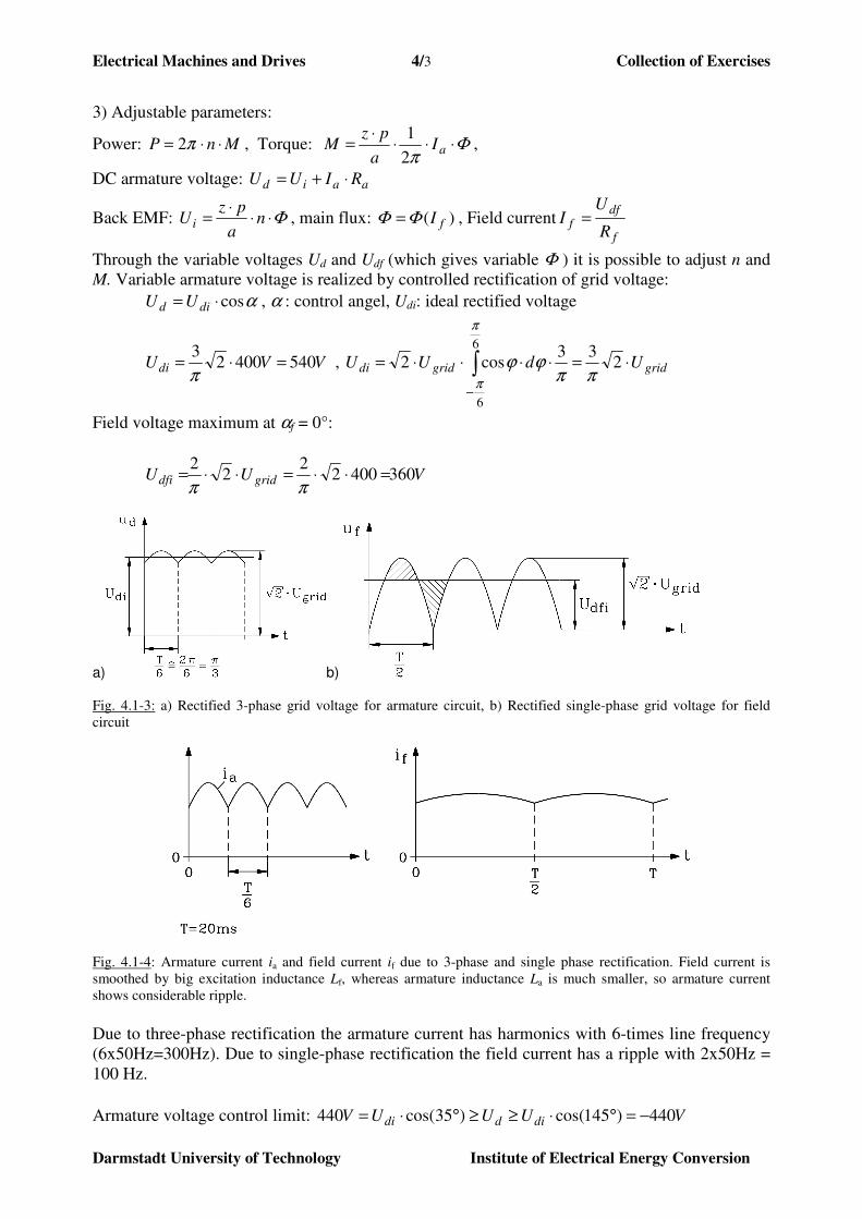
2) Voltage-speed-curve, armature current and main flux, depending on speed, for drive data: Fig.
4.1-2.

Electrical Machines and Drives 4/2 Collection of Exercises
Darmstadt University of Technology Institute of Electrical Energy Conversion
Fig. 4.1-2: Voltage-speed-curve, armature current and main flux, depending on speed
Electrical Machines and Drives 4/3 Collection of Exercises
Darmstadt University of Technology Institute of Electrical Energy Conversion
3) Adjustable parameters:
Power: MnP ⋅⋅= π2 , Torque: Φπ
⋅⋅⋅⋅
= aIa
pzM
2
1,
DC armature voltage: aaid RIUU ⋅+=
Back EMF: Φ⋅⋅⋅
= na
pzU i , main flux: )( fIΦΦ = , Field current
f
dff
R
UI =
Through the variable voltages Ud and Udf (which gives variable Φ ) it is possible to adjust n and
M. Variable armature voltage is realized by controlled rectification of grid voltage:
αcos⋅= did UU , α : control angel, Udi: ideal rectified voltage
VVUdi 54040023
=⋅=π
, gridgriddi UdUU ⋅=⋅⋅⋅⋅= ∫−
233
cos26
6
ππϕϕ
π
π
Field voltage maximum at αf = 0°:
VUU griddfi 36040022
22
=⋅⋅=⋅⋅=ππ
a) b)
Fig. 4.1-3: a) Rectified 3-phase grid voltage for armature circuit, b) Rectified single-phase grid voltage for field
circuit
Fig. 4.1-4: Armature current ia and field current if due to 3-phase and single phase rectification. Field current is
smoothed by big excitation inductance Lf, whereas armature inductance La is much smaller, so armature current
shows considerable ripple.
Due to three-phase rectification the armature current has harmonics with 6-times line frequency
(6x50Hz=300Hz). Due to single-phase rectification the field current has a ripple with 2x50Hz =
100 Hz.
Armature voltage control limit: VUUUV diddi 440)145cos()35cos(440 −=°⋅≥≥°⋅=
Electrical Machines and Drives 4/4 Collection of Exercises
Darmstadt University of Technology Institute of Electrical Energy Conversion
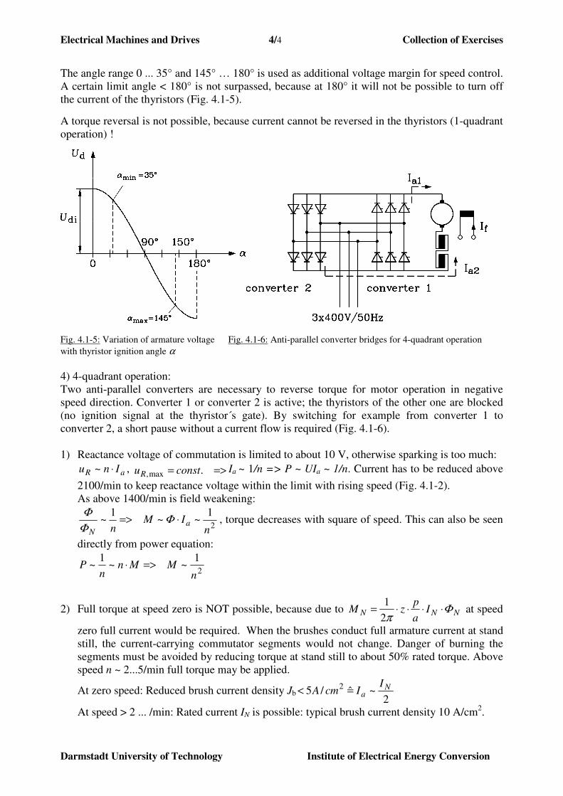
The angle range 0 ... 35° and 145° … 180° is used as additional voltage margin for speed control.
A certain limit angle < 180° is not surpassed, because at 180° it will not be possible to turn off
the current of the thyristors (Fig. 4.1-5).
A torque reversal is not possible, because current cannot be reversed in the thyristors (1-quadrant
operation) !
Fig. 4.1-5: Variation of armature voltage Fig. 4.1-6: Anti-parallel converter bridges for 4-quadrant operation
with thyristor ignition angle α
4) 4-quadrant operation:
Two anti-parallel converters are necessary to reverse torque for motor operation in negative
speed direction. Converter 1 or converter 2 is active; the thyristors of the other one are blocked
(no ignition signal at the thyristor´s gate). By switching for example from converter 1 to
converter 2, a short pause without a current flow is required (Fig. 4.1-6).
1) Reactance voltage of commutation is limited to about 10 V, otherwise sparking is too much:
aR Inu ⋅~ , =>= .max, constuRIa ~ 1/n => P ~ UIa ~ 1/n. Current has to be reduced above
2100/min to keep reactance voltage within the limit with rising speed (Fig. 4.1-2).
As above 1400/min is field weakening:
2
1~~
1~
nIM
na
N
⋅=> ΦΦ
Φ, torque decreases with square of speed. This can also be seen
directly from power equation:
2
1~~
1~
nMMn
nP =>⋅
2) Full torque at speed zero is NOT possible, because due to NNN Ia
pzM Φ
π⋅⋅⋅⋅=
2
1 at speed
zero full current would be required. When the brushes conduct full armature current at stand
still, the current-carrying commutator segments would not change. Danger of burning the
segments must be avoided by reducing torque at stand still to about 50% rated torque. Above
speed n ~ 2...5/min full torque may be applied.
At zero speed: Reduced brush current density Jb2
~ˆ/5 2 Na
IIcmA =<
At speed > 2 ... /min: Rated current IN is possible: typical brush current density 10 A/cm2.

Electrical Machines and Drives 4/5 Collection of Exercises
Darmstadt University of Technology Institute of Electrical Energy Conversion
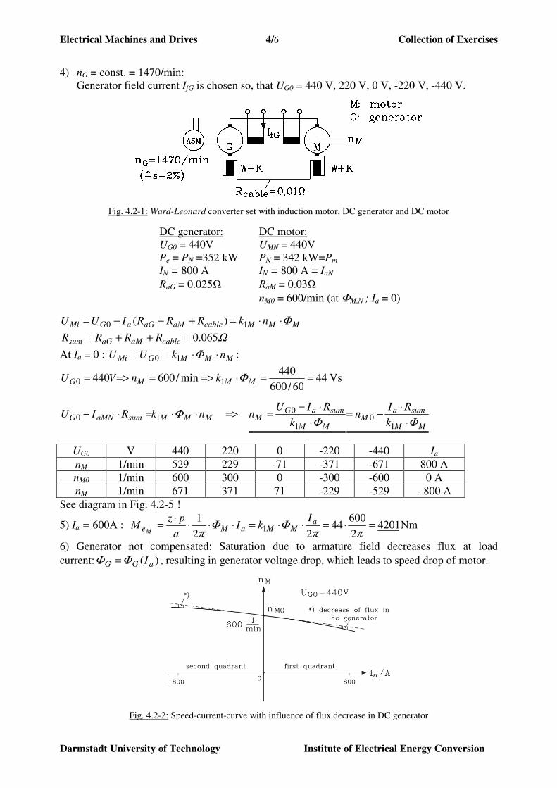
Exercise 4.2: Ward-Leonard rotating converter
A Ward-Leonard converter set, installed 1955, is after refurbishment still in use as a variable
speed elevator drive in a salt mine. The DC generator is driven by a 4-pole cage induction motor,
which is supplied by the 3-phase 400 V/50Hz-grid. The data of the separately excited DC
generator are:
DC Generator: UG,N = 440 V, PN = 352 kW, IN = 800 A, nG,N = 1470/min
RG,a+K+W = 0.025 Ω, (a: armature, K: compensation, W: commutation winding).
The speed of the generator is determined by the driving induction motor. Due to the small slip
variation it is assumed to be constant independent of load. The DC generator supplies a
separately excited DC motor as a variable speed drive with variable DC armature voltage. Data
of the DC motor are:
DC motor: UM,N = 440 V, PN = 324 kW, IaN = 800 A, RM,a+K+W = 0.030 Ω, nM,0 = 600/min: No-
load speed (Ia = 0) at nominal excitation. The DC motor operates at constant nominal excitation.
The DC motor armature winding is connected to the DC generator armature circuit with two
copper cables with a total DC resistance of Rcable = 0.01 Ω.
1.) Why should DC generator and DC motor be designed for the same rated current and voltage?
2.) Why is for the same armature voltage and current rating the rated power of the DC motor
smaller than of the DC generator ?
3.) How big is lip of driving induction machine ?
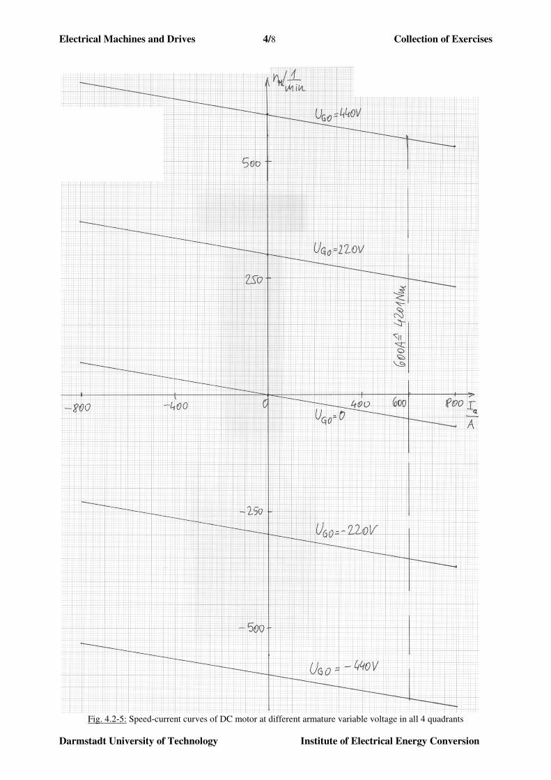
4.) Draw the speed-current-curve nM = f(Ia) of the DC motor as a four quadrant drive for a fixed
excitation of the DC generator at no-load voltages UG0 = 440 V, 220 V, 0 V , -220 V, -440 V.
Neglect the voltage drop at the motor and generator brushes. Scale: Abscissa: 100 A/cm,
Ordinate: 50 min-1
/cm.
5.) Calculate the torque of the DC motor at the generator voltages of 4) at Ia = 600A.
6.) Now we assume, that the compensating winding of the DC generator is NOT used. Sketch
the speed-current-curve nM = f(Ia) at UG0 = 440V in the first and second quadrant
qualitatively. (Note: Motor is still compensated !). Explain the diagram !
7.) In reality the generator speed will vary between no-load and load due to the slip variation of
the driving induction machine. Assume, that due to slip the speed of DC generator drops at
rated load by 4%. Calculate and sketch the speed-current-curve nM = f(Ia) in the first and
second quadrant at generator no-load armature voltage UG0 = 440V. Both DC-machines are
compensated.
Solution:
1) DC generator and DC motor are designed for the same rated current and voltage, because
both armature circuits are connected in series, so generator armature current is also motor
armature current. Motor armature voltage is – compared to generator armature voltage - only
smaller by the voltage drop at the connective cables, so both voltage ratings should be the
same.
2) Motor rated power is its mechanical output power, whereas generator rated power is its
electrical output power, which is the input power of the motor. So motor rated power is
smaller by the motor losses than the electric input power.
3) Generator rated speed is induction motor rated speed: n = 1470/min. So induction motor slip
is %22/50
)60/1470(2/50
/
/=
−=
−=
pf
nfs
grid
grid
Electrical Machines and Drives 4/6 Collection of Exercises
Darmstadt University of Technology Institute of Electrical Energy Conversion
4) nG = const. = 1470/min:
Generator field current IfG is chosen so, that UG0 = 440 V, 220 V, 0 V, -220 V, -440 V.
Fig. 4.2-1: Ward-Leonard converter set with induction motor, DC generator and DC motor
DC generator: DC motor:
UG0 = 440V UMN = 440V
Pe = PN =352 kW PN = 342 kW=Pm
IN = 800 A IN = 800 A = IaN
RaG = 0.025Ω RaM = 0.03Ω
nM0 = 600/min (at ΦM,N ; Ia = 0)
MMMcableaMaGaGMi nkRRRIUU Φ⋅⋅=++−= 10 )(
Ω065.0=++= cableaMaGsum RRRR
At Ia = 0 : MMMGMi nkUU ⋅⋅== Φ10 :
4460/600
440min/600440 10 ==⋅=>==>= MMMG knVU Φ Vs
MM
sumaM
MM
sumaGMMMMsumaMNG
k
RIn
k
RIUnnkRIU
ΦΦΦ
⋅
⋅−=
⋅
⋅−==>⋅⋅=⋅−
10
1
010
UG0 V 440 220 0 -220 -440 Ia
nM 1/min 529 229 -71 -371 -671 800 A
nM0 1/min 600 300 0 -300 -600 0 A
nM 1/min 671 371 71 -229 -529 - 800 A
See diagram in Fig. 4.2-5 !
5) Ia = 600A : 42012
60044
22
11 =⋅=⋅⋅=⋅⋅⋅
⋅=
ππΦΦ
πa
MMaMe
IkI
a
pzM
MNm
6) Generator not compensated: Saturation due to armature field decreases flux at load
current: )( aGG IΦΦ = , resulting in generator voltage drop, which leads to speed drop of motor.
Fig. 4.2-2: Speed-current-curve with influence of flux decrease in DC generator

Electrical Machines and Drives 4/7 Collection of Exercises
Darmstadt University of Technology Institute of Electrical Energy Conversion
Decrease of flux is independent of current flow direction, so it depends on absolute value |±Ia| =>
At small current no saturation occurs, and hence no flux decrease: GGGG nkU ⋅⋅= Φ10 . At Ia
of about rated current flux decreases, therefore generator voltage drops; hence motor speed nM
will drop in addition to speed drop due to resistance voltage drop RsumIa.
7) Induction machine: Slip varies linear with load torque for torque range up to rated torque acc.
to KLOSS function linearization at slip zero : MASM ~ s = 1 - nG/nG0. nG0 =1500/min = nsyn,ASM
Fig. 4.2-3: Speed-torque curve of induction motor and linearization at zero slip.
nASM = nG0: at no load : MASM = MG = 0: Ia = 0: 1500/min
nASM = nG: drops at load: MASM = MG > 0: Ia > 0.
At rated current: -4%: (1-0.04).1500 = 1440/min
Generator speed drop leads to generator voltage drop at constant generator flux: ΦG = const.
Generator no-load voltage: GGGG nkU ⋅⋅= Φ10
Generator voltage at load current Ia : ( )NaGG IIUU /04.010 ⋅−⋅=
Note: In second quadrant power flow direction reverses. Induction machine is generator, slip is
negative, generator speed increases, and so does generator voltage.
So DC motor speed will drop in 1st quadrant/ increase in 2
nd quadrant, in addition to speed drop
due to resistive voltage drop RsumIa.
MM
sumaN
aG
Mk
RII
IU
nΦ⋅
⋅−⋅−⋅
=1
0 )04.01(
Ia = IaMN: 50542.844
5204.0440440 1 ==−⋅−
= −snM /min
Ia = -IaMN: 69544
5204.0440440=
+⋅+=Mn /min
Fig. 4.2-4: Speed-current curve of DC motor at variable speed of induction motor
Electrical Machines and Drives 4/8 Collection of Exercises
Darmstadt University of Technology Institute of Electrical Energy Conversion
Fig. 4.2-5: Speed-current curves of DC motor at different armature variable voltage in all 4 quadrants
Electrical Machines and Drives 4/9 Collection of Exercises
Darmstadt University of Technology Institute of Electrical Energy Conversion
Exercise 4.3: D.C. drive for a coal-mine vehicle
In a coal-mine at South Africa, electric vehicles are used to transport the coal, in order to avoid
exhaust gases of combustion vehicle, which is not allowed in underground environment. The
electric vehicles are equipped with series-excited DC machines as vehicle drives. The DC
machines are operated by vehicle battery and have following electrical data
UN = 440 V, IN = 500 A,
Winding data:
Ra = 0.02 Ω armature resistance
RW + RRS = 0.025 Ω commutation and series excitation winding
NRS = 10 number of turns per pole of the series excitation winding
k1 = z ⋅ (p/a) = 416 armature constant
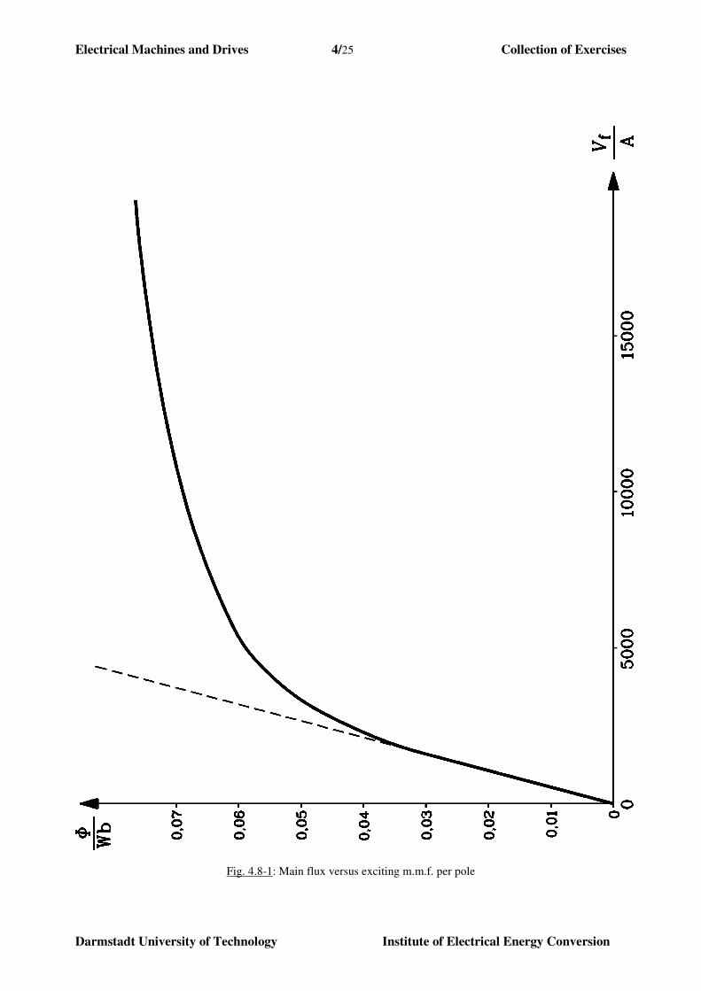
The characteristic of main flux versus exciting Ampere turns is given in Fig. 4.3-1. The brush
voltage drop may be neglected !
1) How big is magnetic main flux Φ at nominal voltage and current?
2) What is the machine speed at nominal voltage and nominal current?
3) At nominal voltage, the machine is overloaded with Ia = 2⋅IN. What is now the speed
value?
4) Calculate rated torque and torque at Ia = 2⋅IN ! Compare current, speed and torque for
100% and 200% rated current!
5) Machine shall be started from standstill with a current of 1.5⋅IN. How big is the necessary
series starting resistor Rv in armature circuit?
6) If wheel vehicle will lose friction contact (“sliding”), load torque decreases to zero = no-
load condition Ia ≈ 0. In that case, machine speed must be limited to 1.5-times rated
speed. How big are the necessary Ampere turns ( NSΘ per pole), which must be designed
by an additional parallel excitation winding in order to fulfil this requirement?
Solution:
1) UN = 440 V, IN = 500 A, Ra = 0.02 Ω, RW+RS = 0.025 Ω
NRS = 10 / pole, 4161 =⋅=a
pzk
Series excitation means Ia = If = IN. So exciting Ampere turns are: aRSf IN ⋅=Θ
Wb0425.0 :1-4.3 Fig. kA 5A50010f ===→=⋅= NRS ΦΦΦΘ
2) totaiN RIUU ⋅+= , Ub ≈ 0, Φ⋅⋅⋅= na
pzUi , Rtot = Ra+W+RS = 0.045 Ω
V5.417V045.0500440i U =⋅−=
111
1
i min 1417s 6.23s 0425.0416
5.417 −−− ==⋅
=⋅
=N
Nk
Un
Φ

Electrical Machines and Drives 4/10 Collection of Exercises
Darmstadt University of Technology Institute of Electrical Energy Conversion
Fig. 4.3-1: Main flux versus excitation Ampere turns of DC series excited machine
3) Ia = 2IN: V 395V 045.05002440*
i =⋅⋅−=U
Wb051.0 :A 10000A 105002 *f ==⋅⋅= ΦΘ

Electrical Machines and Drives 4/11 Collection of Exercises
Darmstadt University of Technology Institute of Electrical Energy Conversion
111
*1
*i* min 1117s 6.18s
051.0416
395 −−− ==⋅
=⋅
=Φk
Un
4) 6.3376051.010004162
1
2
1 **a
* =⋅⋅⋅=⋅⋅⋅⋅=π
Φπ
Ia
pzM Nm
9.14060425.05004162
1
π2
1NNN =⋅⋅⋅=⋅⋅⋅⋅=
πΦI
a
pzM Nm
4.20425.0
051.02
NN
**a
N
*
=⋅=⋅
⋅=
Φ
Φ
I
I
M
M
Speed Armature
current
Torque
1/min A Nm
(1) 1417 500 1406.9
(2) 1117 1000 3376.6
(2) / (1) 0.79 2 2.4
Fig. 4.3-2: Dependence of torque and current of speed in series excited DC motor is slightly different due to iron
saturation (Fig. 4.3-1)
5) Stand still: n = 0 → Ui = 0: vtotN
NvtotaN
51 )(0 RR
I.
URRIU =−
⋅⇒+⋅+=
N5.1 I⋅ = 750 A: Series starting resistor ΩΩ 542.0 045.05005.1
440v =−
⋅=R
6) Auxiliary parallel excitation winding to prevent motor to speed up to infinite speed at
zero load:
Necessary Ampere turns: fNSNS IN ⋅=Θ for n0 = 1.5nN
Zero load: :0a =I ΦRS = 0:
ΦΦΦ ==⋅⋅
=⇒=⋅== Wb03.0 Wb6.235.1416
440 . :0 NSNNS01a UnkUI .
From diagram 4.3-1 we get: A 2400 NS =⇒ Θ .
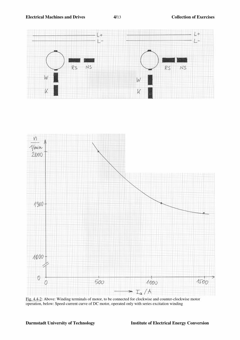
Exercise 4.4: DC Motor for Rotary Frequency Converter
A synchronous generator is driven by a DC motor with variable speed to serve as a variable
frequency converter with sinusoidal voltage in a university´s lab. The DC motor is shunt-excited,
with an auxiliary series excitation winding. The armature circuit comprises further the
commutation and compensating winding.

Electrical Machines and Drives 4/12 Collection of Exercises
Darmstadt University of Technology Institute of Electrical Energy Conversion
DC motor data:
UN = 440 V, IaN = 120 A, nN = 1500/min
Total armature winding resistance:
Rtot = Ra + RW + RK + RRS = 0.3 Ω .
a = armature winding: terminals A1, A2 W = commutation pole winding: terminals B1,
B2
K = compensation winding: terminals C1, C2 RS = series excitation winding: terminals D1, D2
NS = shunt excitation winding: terminals E1, E2
1) Draw the electric circuit of DC machine armature and excitation for motor operation in
a) clockwise and
b) anti-clockwise
direction of rotation (see Fig. 4.4-1). For battery feeding (= fixed armature voltage) a
series starting resistor in the armature circuit and a variable field circuit resistor for
excitation control is needed. Check proper terminal connections! What do we have to
consider in case of reversal of armature current, concerning the series excitation ?
2) Design the value of the necessary starting resistor, which enables the motor to start from
standstill with 1.5⋅IaN ? The brush voltage drop may be neglected!
3) The speed-current characteristic of the motor was measured as a pure series excited DC
motor; the shunt excitation winding circuit was not connected (Fig. 4.4-1). The series
excitation winding has NRS = 5 turns per pole. Choose the Ampere turns NNS ⋅ If per pole
of the shunt excitation winding to enable the motor to operate at nominal load (Ia = IaN)
with nominal speed. Neglect for that case the armature winding voltage drop Ia ⋅ Rtot !
How big is the ratio of Ampere turns of series and shunt excitation !
Solution:
1)
Fig. 4.4-1: Proper connection of winding terminals to the battery grid L+, L- for DC motor operation in a) 1st and b)
3rd
quadrant
Clockwise rotation: This means, that the shaft is rotating in the clockwise direction, when seen
from the front of the motor at the drive-end (Fig. 4.4-2). If this is motor
operation, it is called 1st quadrant operation.
Electrical Machines and Drives 4/13 Collection of Exercises
Darmstadt University of Technology Institute of Electrical Energy Conversion
Fig. 4.4-2: Above: Winding terminals of motor, to be connected for clockwise and counter-clockwise motor
operation, below: Speed-current curve of DC motor, operated only with series excitation winding
Electrical Machines and Drives 4/14 Collection of Exercises
Darmstadt University of Technology Institute of Electrical Energy Conversion
Fig. 4.4-3: Clockwise operation of motor Fig. 4.4-4: Direction of motor torque Rules of drawing the electric circuit: Rotor current in stator field give rotor conductor LORENTZ
forces, which rotate the rotor into direction of positive main field =
direction of electromagnetic motor torque (Fig. 4.4-3) !
a) As the direction of Me is also the direction of n at motor operation ⇒ clockwise speed
direction needs clockwise torque direction (Fig. 4.4-1, left).
b) For counter-clockwise rotation armature current must be reversed.
Series excitation winding at current reversal:
For current reversal, the connection of terminals D1, D2 of series excitation winding must be
exchanged: connection D2-C2 instead of D1-C2. Otherwise, the series winding field would
counter-act the shunt winding field, thus decreasing the main flux.
2) )( totvaiBatt RRIUU +⋅+= , Φ⋅⋅= nkU 1i
n = 0 : Na 5.1 II ⋅= ; UBatt = UN ; Ui = 0
⇒ ΩΩ 14.2 3.01205.1
440tot
a
Nv =−
⋅=−= R
I
UR
3) a) At open shunt excitation winding connections (Fig. 4.4-2):
NRS = 5 / pole, If = 0 : nN = 1500 min-1
: totai RIUUBatt ⋅+= :
Neglecting Ia ⋅ Rtot , we get Φ⋅⋅== N1iN nkUU . Acc. to Fig. 4.4-2 we get at that speed
the current Ia = 1100 A. kA 5.5A 11005aRS =⋅=⋅== INRSΘΘ to get main flux
)(ΘΦΦ = .
b) At series AND shunt excitation we need the same Ampere turns for the same main
flux: A 5500fNSaRS =⋅+⋅=+= ININNSRS ΘΘΘ at UN, nN.
Thus we need at UN, nN due to IaN = 120 A ⇒ A 6005A 120RS =⋅=Θ for the shunt
excitation winding A 4900A 6005500fNSNS =−=⋅= INΘ .
Excitation ratio: %2.124900/600/ ==NSRS ΘΘ
Conclusion:
The main part of the necessary exciting Ampere turns are provided by the shunt excitation
winding. Hence, the series excitation is only an auxiliary one.
Exercise 4.5: DC Motor for DC railway vehicle
In a copper mine in Chile DC powered railway vehicles for transporting copper ore are used. DC
series excited motors with following data are used as traction drives:
UN = 440 V, IN = 500 A
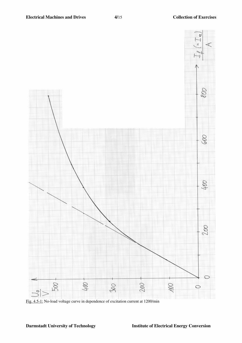
The no-load voltage-exciter current characteristic of the machine is given in Fig. 4.5-1, measured
at separated excitation and Ia = 0, n = n0 = 1200/min. The motor is compensated and has a total
Electrical Machines and Drives 4/15 Collection of Exercises
Darmstadt University of Technology Institute of Electrical Energy Conversion
Fig. 4.5-1: No-load voltage curve in dependence of excitation current at 1200/min
Electrical Machines and Drives 4/16 Collection of Exercises
Darmstadt University of Technology Institute of Electrical Energy Conversion
resistance of armature circuit (including compensating, commutation and series excitation
winding) Rtot = Ra + RW + RK + RRS = 0.045 Ω.
1) At which speed is the motor rotating, if it is operated at U = 220V and a load current I =
400 A ? Neglect the brush voltage drop.
2) Describe motor performance, starting from condition of 1), if the friction contact between
wheel and rail is lost at wet weather condition. Note, that the armature voltage is kept
constant.
3) Electric braking of the railway vehicle: How big is the necessary load resistor RB which
enables the machine as a generator at braking condition to generate a current I = 500 A at
n = 600/min ? Determine terminal voltage and the electrical braking power in the load
resistor !
4) With the condition of 3), what happens, when the speed decreases towards zero at a
constant load resistor RB?
Solution:
1) Series excited motor, operated at Ia = 400 A and 220 V:
totaibtotai RIUURIUU ⋅+≅+⋅+= . At series excitation armature current is
excitation current: )( a1i InkU Φ⋅⋅= . According to Fig. 4.5-1 we get at n0 = 1200/min
and 400 A excitation current a no-load voltage: V 400)(A400a010
a=⋅⋅==
=Ii InkUU Φ .
From that we derive the ratio Vs 2060/1200
400)( a1
0
0 ==⋅= Ikn
UΦ . At 220 V we get at
load:
11totaa1 min606s 1.10
20
045.0400220)400(V 220 −− ==
⋅−=⇒⋅+=⋅⋅== nRIAIknU Φ
2) If the load at the shaft is completely removed, torque is zero: Me = 0. So, armature current
is zero: Ia = 0 and hence flux is zero 0→Φ . Due to V 2201 ==⋅⋅ Ukn Φ = const., speed
n rises rapidly, the machine „over-speeds“ and will be destroyed.
3) Series excited generator with a load resistance RB at n = 600 min-1
, Ia = 500 A:
)( a1atotaBi InkIRIRU Φ⋅⋅=⋅+⋅=
According to Fig. 4.5-1: At 1200/min, V 440)A 500( a010 ==⋅⋅= InkU Φ , we get the
ratio Vs 2260/1200
440)A 500( a1 ===⋅ Ik Φ , and with that the proper value for load
resistance at 600/min, 500 A:
ΩΦ
395.0500
500045.02260
600
)(
a
atota1B =
⋅−⋅=
⋅−⋅⋅=
I
IRInkR
The terminal voltage at the resistor is V 5.197500395.0aB =⋅=⋅= IRU . The dissipated
braking power in the load resistor is kW 75.98a =⋅= IUP .
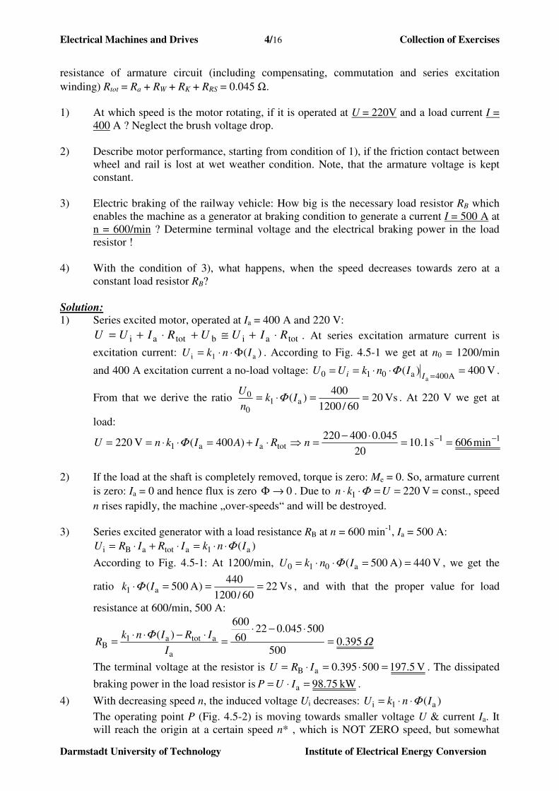
4) With decreasing speed n, the induced voltage Ui decreases: )( a1i InkU Φ⋅⋅=
The operating point P (Fig. 4.5-2) is moving towards smaller voltage U & current Ia. It
will reach the origin at a certain speed n* , which is NOT ZERO speed, but somewhat
Electrical Machines and Drives 4/17 Collection of Exercises
Darmstadt University of Technology Institute of Electrical Energy Conversion
lower than n1/2. Then the generator braking operation with RB is not possible any longer
below this minimum speed n*, because the armature current is already zero. Hence,
below n*, the machine is braking only by its (small) friction losses.
Fig. 4.5-2: Series excited generator operation at decreasing speed.
Note: The saturation effect, which is curbing the Ui(n) curve, is necessary for operating the series
excited generator on a resistor. Otherwise, no intersection between atotB )( IRRUi ⋅+= and
)( a1i InkUU Φ⋅⋅== exists.
Exercise 4.6: DC Motor for a printing machine
For the movement of the paper inside a printing machine, a variable speed DC drive shall be
designed. A separately excited dc machine with a compensation winding and the following rated
data has been chosen:
UN = 440 V, IN = 120 A
The total armature resistance is Ra = 0.3 Ω. The open circuit voltage as a function of the exciting
Ampere turns U0 = f(Θ f) has been measured (Fig. 4.6-1) at a rotor speed n = 500 min-1
. During
final testing at the manufacturer´s test bench it was revealed, that due to over-commutation, the
speed of the machine (at U = UN and constant excitation) INCREAESES from nN = 600 min-1
under no-load conditions linearly to n = 618 min-1
at Ia = IN.
1) Determine the exciting Ampere turns Θ f, for which the motor no-load speed will be n0 =
600 min-1
.
2) How do we have to choose the number of turns per pole of an auxiliary series excitation
winding, so that for operation at rated voltage and excitation according to 1) the speed
will be n0 = 600 min-1
and at Ia = IN the speed will be n = 550 min-1
? Neglect the
resistance of the auxiliary series excitation winding.
3) At the customer, the machine shall be operated without auxiliary series excitation
winding, being supplied by a 6-pulse controlled rectifier bridge. Sketch the electric circuit
of the DC drive for one quadrant operation acc. to 3).
4) The voltage drop at the bridge due to current overlapping of two phases during the current
commutation from one thyristor to the next, is considered by an equivalent armature
resistance 0.15 Ω. Does the speed characteristic n = f(Ia) for a constant voltage Ud0 = 440
V and an excitation according to 1) still INCREASE with load in the range of 0 ≤ Ia ≤ IN ?
(Ud0: Rectified DC voltage without consideration of current overlapping in the bridge.)
Electrical Machines and Drives 4/18 Collection of Exercises
Darmstadt University of Technology Institute of Electrical Energy Conversion
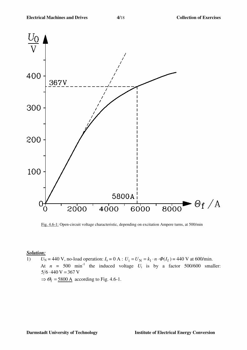
Fig. 4.6-1: Open-circuit voltage characteristic, depending on excitation Ampere turns, at 500/min
Solution:
1) UN = 440 V, no-load operation: Ia = 0 A : )( f1Ni InkUU Φ⋅⋅== = 440 V at 600/min.
At n = 500 min-1
the induced voltage Ui is by a factor 500/600 smaller:
V 367 V 44065 =⋅
A 5800f =⇒Θ according to Fig. 4.6-1.
Electrical Machines and Drives 4/19 Collection of Exercises
Darmstadt University of Technology Institute of Electrical Energy Conversion
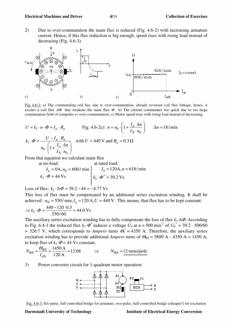
2) Due to over-commutation the main flux is reduced (Fig. 4.6-2) with increasing armature
current. Hence, if this flux reduction is big enough, speed rises with rising load instead of
decreasing (Fig. 4.6-3).
c)
Fig. 4.6-2: a) The commutating coil has, due to over-commutation, already reversed coil flux linkage, hence, it
excites a coil flux ∆Φ that weakens the main flux Φ. b) The current commutates too quick due to too large
commutation field of compoles (= over-commutation). c) Motor speed rises with rising load instead of decreasing.
aa RInkU ⋅+⋅⋅= Φ1 Fig. 4.6-2c): min/18∆∆
10
0 =
+⋅= n
n
n
I
Inn
N
a
Ω 3.0 and V 440 with ∆
10
0
1 ==
+⋅
⋅−=⋅ a
N
a
aa RU
n
n
I
In
RIUk Φ
From that equation we calculate main flux
at no-load: at rated load:
Vs 44
min/600,A0
1
0a
=⋅
==
Φk
nI
Vs 2.39
min/618,A120
1
a
=⋅
==
∗Φk
nI
Loss of flux: Vs 77.4442.39∆1 −=−=⋅ Φk
This loss of flux must be compensated by an additional series excitation winding. It shall be
achieved: V 440,A 120min,/550 aN === UIn . This means, that flux has to be kept constant:
Vs 0.4460/550
3.01204401 =
⋅−=⋅⇒ Φk
The auxiliary series excitation winding has to fully compensate the loss of flux k1⋅∆Φ. According
to Fig. 6.4-1 the reduced flux k1⋅Φ* induces a voltage U0 at n = 500 min
-1 of U0
* = 39.2 ⋅ 500/60
= 326.7 V, which corresponds to Ampere turns Θf* = 4350 A. Therefore, the auxiliary series
excitation winding has to provide additional Ampere turns of ΘRS = 5800 A - 4350 A = 1450 A,
to keep flux of k1⋅Φ = 44 Vs constant.
e turns/pol12 08.12A 120
A 1450RS
aN
RSRS =⇒=== N
IN
Θ
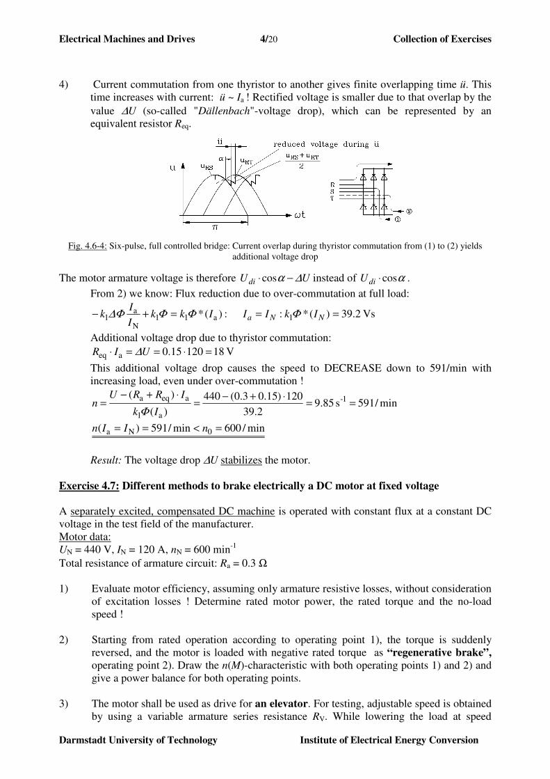
3) Power converter circuit for 1-quadrant motor operation:
Fig. 4.6-3: Six-pulse, full controlled bridge for armature, two-pulse, half controlled bridge (cheaper!) for excitation
Electrical Machines and Drives 4/20 Collection of Exercises
Darmstadt University of Technology Institute of Electrical Energy Conversion
4) Current commutation from one thyristor to another gives finite overlapping time ü. This
time increases with current: ü ~ Ia ! Rectified voltage is smaller due to that overlap by the
value ∆U (so-called "Dällenbach"-voltage drop), which can be represented by an
equivalent resistor Req.
Fig. 4.6-4: Six-pulse, full controlled bridge: Current overlap during thyristor commutation from (1) to (2) yields
additional voltage drop
The motor armature voltage is therefore UUdi ∆α −⋅cos instead of αcos⋅diU .
From 2) we know: Flux reduction due to over-commutation at full load:
Vs 2.39)(*: :)(* 1a11N
a1 ===+− NNa IkIIIkk
I
Ik ΦΦΦ∆Φ
Additional voltage drop due to thyristor commutation:
V 1812015.0aeq =⋅==⋅ UIR ∆
This additional voltage drop causes the speed to DECREASE down to 591/min with
increasing load, even under over-commutation !
min/591s 85.92.39
120)15.03.0(440
)(
)( 1-
a1
aeqa==
⋅+−=
⋅+−=
Ik
IRRUn
Φ
min/600min/591)( 0Na =<== nIIn
Result: The voltage drop ∆U stabilizes the motor.
Exercise 4.7: Different methods to brake electrically a DC motor at fixed voltage
A separately excited, compensated DC machine is operated with constant flux at a constant DC
voltage in the test field of the manufacturer.
Motor data:
UN = 440 V, IN = 120 A, nN = 600 min-1
Total resistance of armature circuit: Ra = 0.3 Ω
1) Evaluate motor efficiency, assuming only armature resistive losses, without consideration
of excitation losses ! Determine rated motor power, the rated torque and the no-load
speed !
2) Starting from rated operation according to operating point 1), the torque is suddenly
reversed, and the motor is loaded with negative rated torque as “regenerative brake”,
operating point 2). Draw the n(M)-characteristic with both operating points 1) and 2) and
give a power balance for both operating points.
3) The motor shall be used as drive for an elevator. For testing, adjustable speed is obtained
by using a variable armature series resistance RV. While lowering the load at speed
Electrical Machines and Drives 4/21 Collection of Exercises
Darmstadt University of Technology Institute of Electrical Energy Conversion
inversion after the lifting operation), the motor is operating as a braking generator. To
which value does RV need to be adjusted in order to provide lowering braking at –nN at
rated torque (operating point 3)? Draw the n(M)-characteristic with operating point 1) and
3). Give a power balance for point 3).
4) The motor armature is – starting from operating point 1 – disconnected from the grid and
switched to a braking resistor RB. The motor acts as a braking generator, dissipating the
power as heat in the braking resistor. How big must RB be, so that the motor brakes with
rated torque (operating point 4)? Draw the n(M)-characteristic with operating point 1) and
4). Give a power balance for point 4).
5) The motor armature supply voltage is – starting from operating point 1 – reversed to the
negative rated voltage. This causes a current reversal, which yields negative motor
torque, thus braking the motor.
a) How big is the armature current directly after reversing the voltage polarity?
b) Is this operating condition permissible?
c) How big does an armature series resistor RV need to be, to ensure rated current after
the voltage reversal (operating point 5)?
d) Draw the n(M)-characteristic with operating point 1) and 5). Give a power balance for
point 5). Why does the motor need to be disconnected from the grid during braking
operation?
Solution:
1)
/min5.6536003.0120440
440
:)excitation (separate . ,
Nm 6.771)60/600(2
48480
2
W48480432052800
%82.9152800
432052800
W52800120440
losses" total" W 43201203.0
NaaN
N0
N
aNN1
1
aNN
1
iN
1
N011i
N
NN
CuNin,mNN
in
Cuinmot
NNelin
22NaCu
=⋅⋅−
=⋅−
=
−=⇒
−==
==⋅⋅=
==⋅⋅
=
=−=−==
=−
=−
=
=⋅=⋅==
==⋅=⋅=
nIRU
Un
n
RIUk
Φk
RIU
Φk
Un
Φk
UnconstΦknΦkU
n
PM
PPPP
P
PP
IUPP
IRP
Φ
ππ
η
2)
min/707/s11784.40
476
V 4763.0120440: :2point Operating
: ,
1
i
aNNiaNiN
Na2eaaiN
====
=⋅+=+=−=
⇒−→⋅=⋅+=
Φ
Φ
k
Un
RIUURIUU
MMIkMRIUU N
Electrical Machines and Drives 4/22 Collection of Exercises
Darmstadt University of Technology Institute of Electrical Energy Conversion
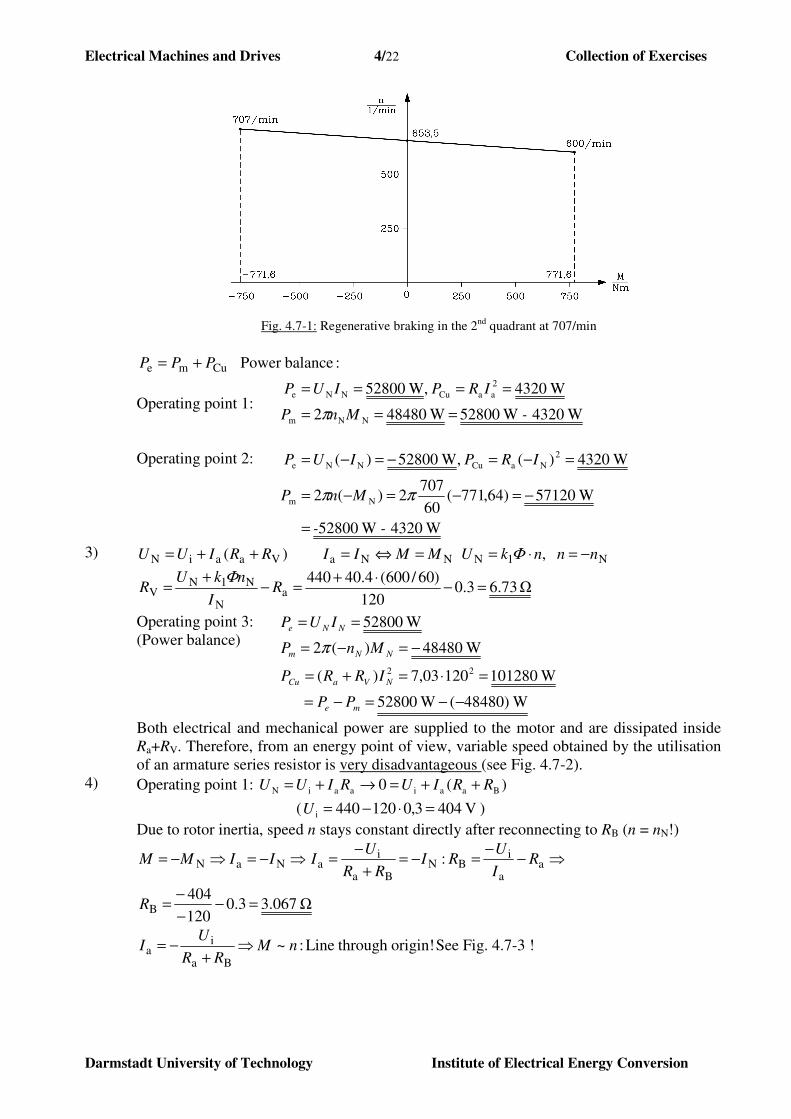
Fig. 4.7-1: Regenerative braking in the 2nd
quadrant at 707/min
:balancePower Cume PPP +=
Operating point 1:
Operating point 2:
W4320 W52800 W484802
W4320 , W52800
NNm
2
aaCuNNe
- MnP
IRPIUP
===
====
π
W4320 W52800
W57120)64,771(60
7072)(2
W4320)( , W52800)(
Nm
2
NaCuNNe
- -
MnP
IRPIUP
=
−=−=−=
=−=−=−=
ππ
3) NNaVaaiN )( MMIIRRIUU =⇔=++= N1N , nnnkU −=⋅= Φ
Ω 73.63.0120
)60/600(4.40440a
N
N1NV =−
⋅+=−
+= R
I
nkUR
Φ
Operating point 3:
(Power balance)
W)48480( W52800
W10128012003,7)(
W48480)(2
W52800
22
−−=−=
=⋅=+=
−=−=
==
me
NVaCu
NNm
NNe
PP
IRRP
MnP
IUP
π
Both electrical and mechanical power are supplied to the motor and are dissipated inside
Ra+RV. Therefore, from an energy point of view, variable speed obtained by the utilisation
of an armature series resistor is very disadvantageous (see Fig. 4.7-2).
4) Operating point 1: )(0 BaaiaaiN RRIURIUU ++=→+=
( V 4043,0120440i =⋅−=U )
Due to rotor inertia, speed n stays constant directly after reconnecting to RB (n = nN!)
⇒−=⇒−= NaN IIMM ⇒−−
=−=+
−= a
a
iBN
Ba
ia : R
I
URI
RR
UI
Ω 067.33.0120
404B =−
−
−=R
origin! through Line : ~Ba
ia nM
RR
UI ⇒
+−= See Fig. 4.7-3 !

Electrical Machines and Drives 4/23 Collection of Exercises
Darmstadt University of Technology Institute of Electrical Energy Conversion
Operating point 4:
(Power balance)
W48480)(2
W84804120)3,0067,3()(
W00
NNm
22aaBCu
aae
−=−=
−==+=+=
=⋅=⋅=
MnP
PIRRP
IIUP
m
π
The mechanical power Pm is converted into heat inside the braking and armature resistors.
5) Operating point 1:
Operating point 5:
aNN1aaiN RInkRIUU +⋅=+= Φ
aaN1N: RInkUUU +⋅=−−→ Φ Because of the rotor inertia, the
speed n stays constant directly after inverting the armature voltage!
a) )!current rated the times(23.4 )(!A 3.2813
3.0
404440
a
N1Na −=
+−=
⋅−−=
R
nkUI
Φ
! losses rated the times6.5494.23 2 =⇒
b) The winding will be thermally overloaded and destroyed ! Not allowed operating point !
c) Design of series armature resistor to limit over-current:
Ω 73.6A 1203.0
404440VN
VVa
N1Na =⇒−=−=
+
+−=
+
⋅−−= RI
RRR
nkUI
Φ
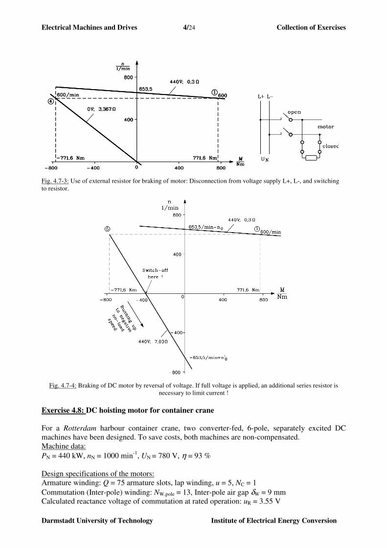
d) See Fig. 4.7-4 for n(M)-curve !
The motor has to be disconnected from the grid at n = 0 min-1
, otherwise it will accelerate
up to 00 nn −=′ .
min/5.6534,40
440)0(
speed load-no new :)(
a1
N0
0Vaa1N
−=−==−
=′
′++⋅=−
Ik
Un
nRRInkU
Φ
Φ
Operating point 5:
(Power balance)
me2NaVCu
NNm
NNe
W101280)(
W48480)(2
W28005)(
PPIRRP
MnP
IUP
−==+=
−=−=
=−⋅−=
π
Fig. 4.7-2: Elevator operation: Lowering of load with series resistor: High resistive losses !
Electrical Machines and Drives 4/24 Collection of Exercises
Darmstadt University of Technology Institute of Electrical Energy Conversion
Fig. 4.7-3: Use of external resistor for braking of motor: Disconnection from voltage supply L+, L-, and switching
to resistor.
Fig. 4.7-4: Braking of DC motor by reversal of voltage. If full voltage is applied, an additional series resistor is
necessary to limit current !
Exercise 4.8: DC hoisting motor for container crane
For a Rotterdam harbour container crane, two converter-fed, 6-pole, separately excited DC
machines have been designed. To save costs, both machines are non-compensated.
Machine data:
PN = 440 kW, nN = 1000 min-1
, UN = 780 V, η = 93 %
Design specifications of the motors:
Armature winding: Q = 75 armature slots, lap winding, u = 5, NC = 1
Commutation (Inter-pole) winding: NW,pole = 13, Inter-pole air gap δW = 9 mm
Calculated reactance voltage of commutation at rated operation: uR = 3.55 V
Electrical Machines and Drives 4/25 Collection of Exercises
Darmstadt University of Technology Institute of Electrical Energy Conversion
Fig. 4.8-1: Main flux versus exciting m.m.f. per pole
Electrical Machines and Drives 4/26 Collection of Exercises
Darmstadt University of Technology Institute of Electrical Energy Conversion
Total armature resistance: Ra = 0.0426 Ω, rotor diameter / length: 0.6 m / 0.24 m
Calculated magnetic characteristic Φ(Vf) according to Fig. 4.8-1.
1) Determine rated armature!
2) How big is the total number of armature conductors z and the number of commutator
segments K ?
3) Calculate the magnetic inter-pole air gap flux density BδW at rated current!
4) How big is the induced voltage into the commutating winding (compole voltage) uW at
rated operation? Is the inter-pole magnetic circuit designed poperly or does the inter-pole
air gap need to be adjusted? If so, how does it need to be changed?
5) Up to which maximum field weakening rotational speed nR can the motor be operated
without exceeding the permissible reactance voltage of commutation?
6) The excitation current shall be If = 24 A at rated operation. Chose the right number of
turns Nf per pole ! Calculate the field current for PN at nR ! In both calculations, take a
brush contact voltage of Ub = 2 V into consideration.
Solution:
1) A 6.606
78093.0
4400001/
N
m
N
mNa, =
⋅=
⋅=⋅==
U
P
U
PUPI Ne
ηη
2) 375575750215752C =⋅=⋅==⋅⋅⋅=⋅⋅⋅= uQKNuQz
3) Lap winding: a = p = 3 , 2p = 6, NW,pole = 13
T 219.06,606109
417.1013104
417.10338
750
8
3
7N
W
polea,poleW,0Wδ,
polea,
=⋅⋅
−⋅=⋅
−=
=⋅⋅
=⋅⋅
=
−−π
δµ I
NNB
pa
zN
4)
V 30.324,0219.04,31122
m 24.0km/h) 113( m/s 4,3160
10006,0
Wδ,aCW
Nra
=⋅⋅⋅⋅=⋅⋅⋅⋅=
===⋅⋅=⋅⋅=
BlvNu
lndv ππ
V 3.3 V 55.3),( NNR >=nIu : The inter-pole winding is designed too weak.
Reducing the inter-pole air gap by adding additional iron sheets helps to correct that.
It shall be: RuuW = !
⇒W
Wδ,W1~~δ
Bu mm 4.837.8955.3
30.3W
R
WcorrW, ≈=⋅== δδ
u
u
5) V 10maxR, =u maximum permissible reactance voltage of commutation !
min/2817
min/281755.3
101000
V 55.3 ,~
maxR
NR,
maxR,Nmax
N
max
N
aRNmaxR,
RNaR
Na
==
=⋅==⇒⋅=
=⋅
=
nn
u
unn
n
n
I
Iuu
unIu
II
Electrical Machines and Drives 4/27 Collection of Exercises
Darmstadt University of Technology Institute of Electrical Energy Conversion
6)
22524
5400/
5400)(
2.60
60
1000
3
3750
2.752
2.75226.6060426.0780
0426.024
==⇒=
=⇒−⇒=
=
⋅⋅
=⇒⋅⋅⋅=⇒
=−⋅−=−⋅−=
+⋅+=
==
ffNf,Nf,
Nf,f
NNiN
baNaNiN
baNaiN
afN
NNVI
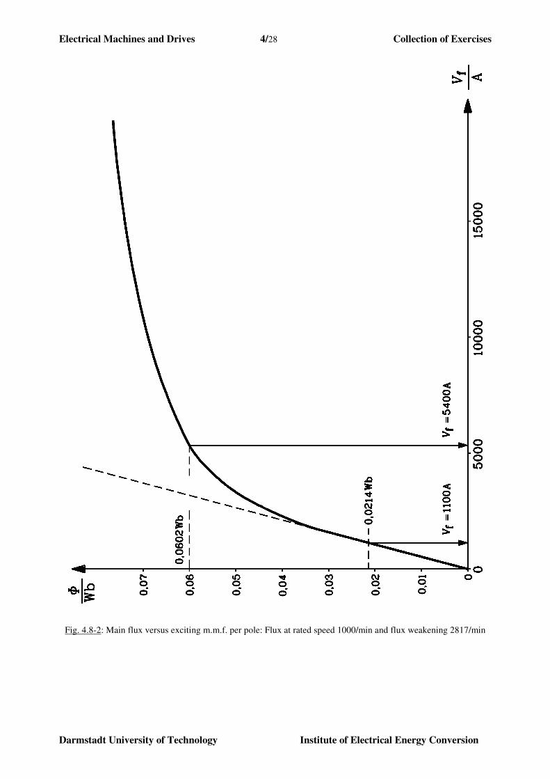
A V2)-4.8 Fig. (see 1-4.8 Fig. sticcharacteriVmWb 60.2
mWb na
pzU
V UIRUU
UIRUU
Ω R A,I
ΦΦ
ΦΦ
at PN, nR:
: efficiency same with theand at alsoA 6.606 RNN
N ηη
nIIU
P N =⇒⋅
=
A 89.4225
1100 A 1100 :get we1-4.8 Fig.
sticcharacteri)( From mWb, 0214.0
60
2817
3
3750
2.752 :min/2817
too.,at V 2.752const.
ff
fR
Ri
==⇒=
−=
⋅⋅
==
===⇒
IV
Vn
nnU
ΦΦ
Electrical Machines and Drives 4/28 Collection of Exercises
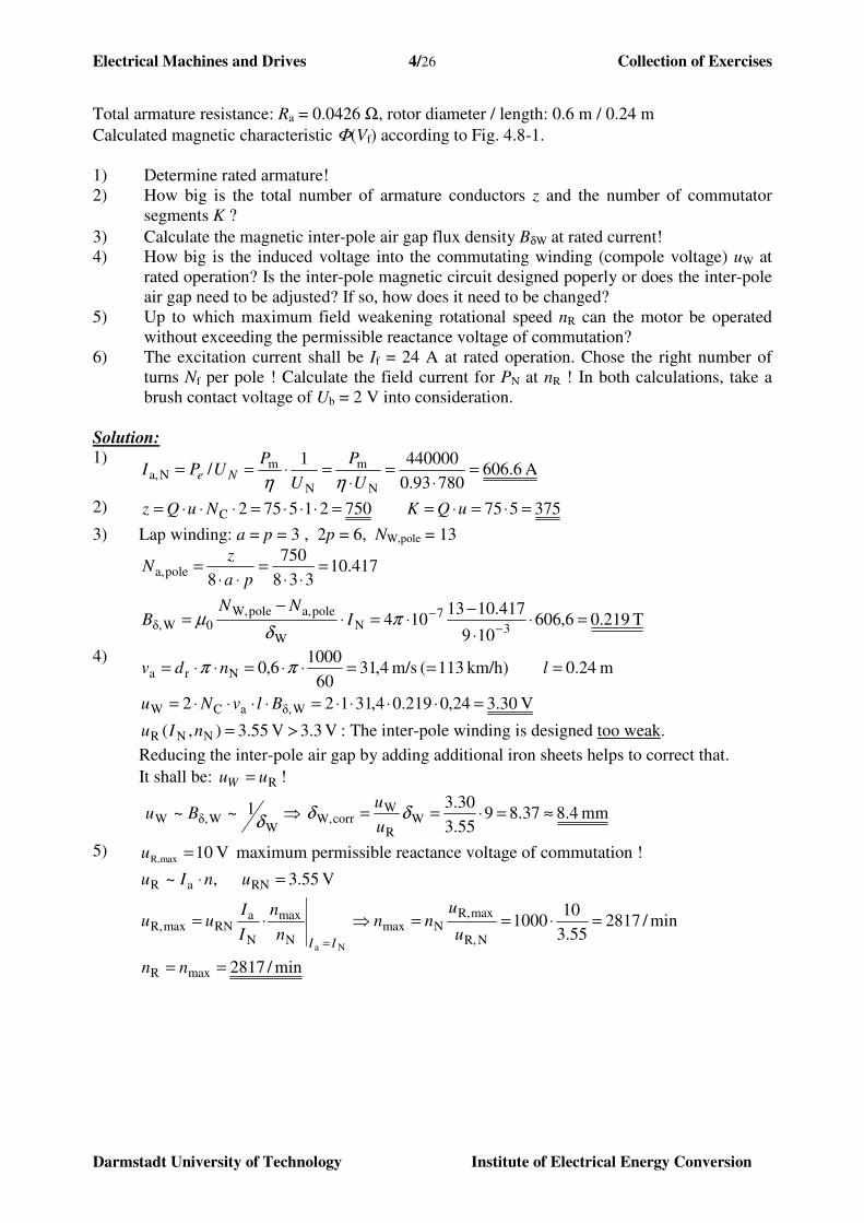
Darmstadt University of Technology Institute of Electrical Energy Conversion
Fig. 4.8-2: Main flux versus exciting m.m.f. per pole: Flux at rated speed 1000/min and flux weakening 2817/min
Top Related