


Languages
Pages
Legal

© 2010 Spirit AeroSystems, Inc. All Rights Reserved Non-Technical Data ECCN: EAR99
"Examples of Substantiation Testing and
Documents to Support Large Areas of Composite
Repair"
"
John M. Welch
Chief Scientist – GCS&S
Technical Fellow – Composite Structures
Global Customer Supply & Support
September 17, 2015
WARNING – This document contains technical data whose export is restricted by the Arms Control Act (Title 22, U.S.C., Sec 2751 et seq.) or the Export Administration Act of 1979, as amended, Title 50 U.S.C., App. 2401 et seq. Violations of these export laws are subject to severe criminal penalties. The Information herein contains Export Controlled Classification Number 1E994
2015 FAA/Bombardier/TCCA/EASA/Industry Composite Transport Damage Tolerance
and Maintenance Workshop Bombardier Aerospace, Montreal, Quebec, Canada, September 17, 2015
James E. Epperson
Sr. Engineering Manager
FAA Structures DER
Global Customer Supply & Support
September 17, 2015
Michael D. Borgman
Sr. Engineering Expert
Composite Structures
Spirit AeroSystems
September 17, 2015

© 2010 Spirit AeroSystems, Inc. All Rights Reserved Non-Technical Data ECCN: EAR99
Jim Epperson
Large area repairs are becoming more common
Damage is not always a result of an impact often times making the repair approach more intricate:
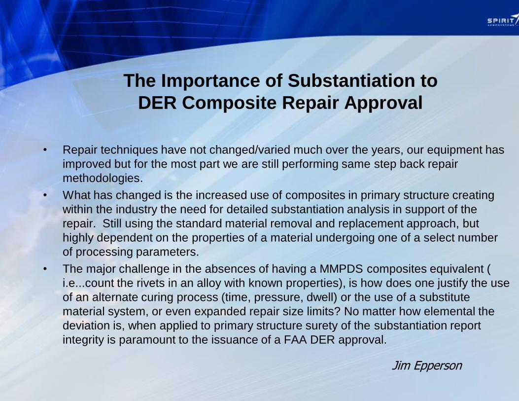
The Importance of Substantiation to
DER Composite Repair Approval
© 2010 Spirit AeroSystems, Inc. All Rights Reserved Non-Technical Data ECCN: EAR99
The Importance of Substantiation to
DER Composite Repair Approval
• Repair techniques have not changed/varied much over the years, our equipment has
improved but for the most part we are still performing same step back repair
methodologies.
• What has changed is the increased use of composites in primary structure creating
within the industry the need for detailed substantiation analysis in support of the
repair. Still using the standard material removal and replacement approach, but
highly dependent on the properties of a material undergoing one of a select number
of processing parameters.
• The major challenge in the absences of having a MMPDS composites equivalent (
i.e...count the rivets in an alloy with known properties), is how does one justify the use
of an alternate curing process (time, pressure, dwell) or the use of a substitute
material system, or even expanded repair size limits? No matter how elemental the
deviation is, when applied to primary structure surety of the substantiation report
integrity is paramount to the issuance of a FAA DER approval.
Jim Epperson
© 2010 Spirit AeroSystems, Inc. All Rights Reserved Non-Technical Data ECCN: EAR99
Jim Epperson
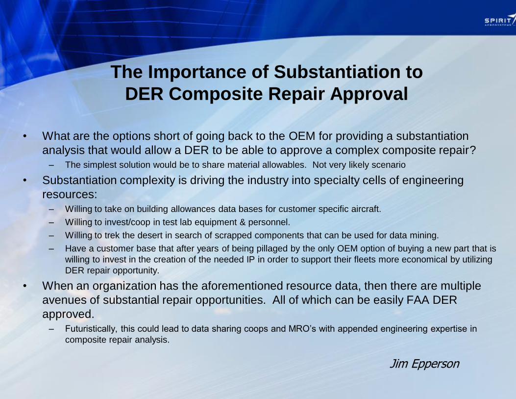
The Importance of Substantiation to
DER Composite Repair Approval
• What are the options short of going back to the OEM for providing a substantiation
analysis that would allow a DER to be able to approve a complex composite repair?
– The simplest solution would be to share material allowables. Not very likely scenario
• Substantiation complexity is driving the industry into specialty cells of engineering
resources: – Willing to take on building allowances data bases for customer specific aircraft.
– Willing to invest/coop in test lab equipment & personnel.
– Willing to trek the desert in search of scrapped components that can be used for data mining.
– Have a customer base that after years of being pillaged by the only OEM option of buying a new part that is
willing to invest in the creation of the needed IP in order to support their fleets more economical by utilizing
DER repair opportunity.
• When an organization has the aforementioned resource data, then there are multiple
avenues of substantial repair opportunities. All of which can be easily FAA DER
approved.
– Futuristically, this could lead to data sharing coops and MRO’s with appended engineering expertise in
composite repair analysis.
© 2010 Spirit AeroSystems, Inc. All Rights Reserved Non-Technical Data ECCN: EAR99
In 2005/2006 time frame, Spirit assisted Boeing by designing a repair kit to comply a condition that existed on 18 aircraft, 72 thrust reverser inner walls. Service Bulletin 777-SB0078 was released, and 18 aircraft at 5 foreign carriers were identified to have an area between 35-36 square feet removed and replaced with structural materials of the same genre, for increased performance. Raw materials were controlled by existing Material Specifications The repair plies were kitted and prepared to a released Engineering Dataset The repair plies were cut and assembled using Production Processes to a known Production Process Specification using Production Tools, Tapes, and Templates Seed Units were built so that units in need of compliance could be removed from the wing and the airplane could return to service – coordinated logistics of the event were arranged at each individual airline, holding tools and transport tools were included Spirit traveled a practiced and proficient repair technician crew to each site to perform removals, repair, and replacement of the thrust reverser elements Spirit arrived with a known NDI plan, and a NDI standard on site, to perform capable NDI after the repair was completed – every unit Substantiation testing included coupon and element level testing Test Results, Structural Analysis, and Repair Methodology were all recorded in a completed Document, MAA7-70023-1 which was later used for Approval
Examples of Practiced Repair – Past Experience, SB0078
© 2010 Spirit AeroSystems, Inc. All Rights Reserved Non-Technical Data ECCN: EAR99
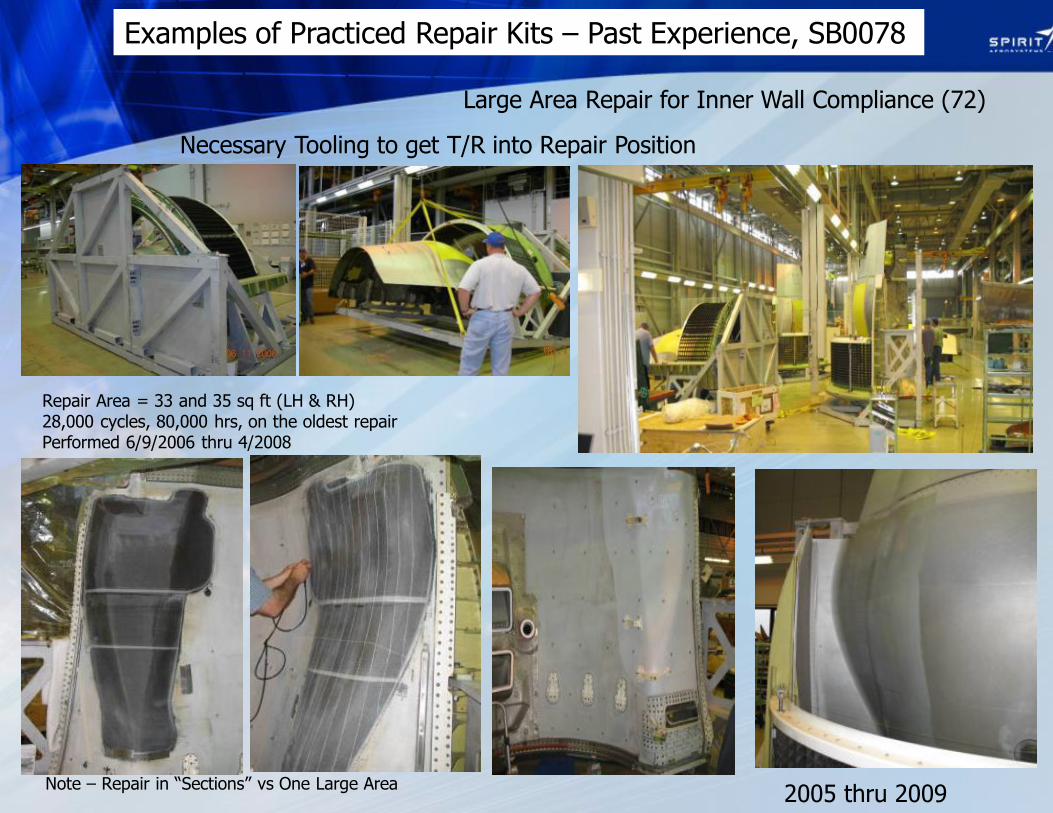
Large Area Repair for Inner Wall Compliance (72)
Necessary Tooling to get T/R into Repair Position
Examples of Practiced Repair Kits – Past Experience, SB0078
Repair Area = 33 and 35 sq ft (LH & RH) 28,000 cycles, 80,000 hrs, on the oldest repair Performed 6/9/2006 thru 4/2008
Note – Repair in “Sections” vs One Large Area 2005 thru 2009

© 2010 Spirit AeroSystems, Inc. All Rights Reserved Non-Technical Data ECCN: EAR99
Large Area Repair for Inner Wall Compliance (72)
Examples of Practiced Repair Kits
Note – Repair in “Sections” vs One Large Area
Example of consolidated repair kit, this one was done out of autoclave
Placement of consolidated repair kit, onto structure
Smoothing kit into sanded recess, tool located and template aligned
Result – Kit is ready to bag and cure – total time involved in place- ment --7 mins
Lesson Learned: A well prepared kit drastically reduces repair time
2005 thru 2009
10 of 32
© 2010 Spirit AeroSystems, Inc. All Rights Reserved Non-Technical Data ECCN: EAR99
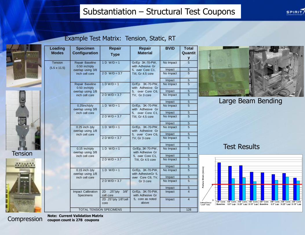
Large Beam Bending
Tension
Compression
Substantiation – Structural Test Coupons
Loading
Modes
Specimen
Configuration
Repair
Type
Repair
Material
BVID Total
Quantit
y
Tension
(5.5 x 11.5)
Repair Baseline
0.50 inch/ply
overlap using 3/8
inch cell core
1 D W/D = 1 Gr/Ep 3K-70-PW,
with Adhesive Gr
5, over Core C1,
TIII, Gr 4.5 core
No Impact 5
Impact 5
2 D W/D = 3.7 No Impact 5
Impact 5
Repair Baseline
0.50 inch/ply
overlap using 1/8
inch cell core
1 D W/D = 1 Gr/Ep 3K-70-PW,
with Adhesive Gr
5, over Core C6,
TV, Gr 3 core
No Impact 5
Impact 5
2 D W/D = 3.7 No Impact 5
Impact 5
0.25inch/ply
overlap using 3/8
inch cell core
1 D W/D = 1 Gr/Ep, 3K-70-PW,
with Adhesive Gr
5, over Core C1,
TIII, Gr 4.5 core
No Impact 5
Impact 5
2 D W/D = 3.7 No Impact 5
Impact 5
0.25 inch /ply
overlap using 1/8
inch cell core
1 D W/D = 1 Gr/Ep, 3K-70-PW,
with Adhesive Gr
5, over Core C6,
TV, Gr 3 core
No Impact 5
Impact 5
2 D W/D = 3.7 No Impact 5
Impact 5
0.15 inch/ply
overlap using 3/8
inch cell core
1 D W/D = 1 Gr/Ep, 3K-70-PW,
with Adhesive Gr
5, over Core C1,
TIII, Gr 4.5 core
No Impact 5
Impact 5
2 D W/D = 3.7 No Impact 5
Impact 5
0.15 inch /ply
overlap using 1/8
inch cell core
1 D W/D = 1 Gr/Ep, 3K-70-PW,
with AdhesiveGr 5,
over Core C6, TV,
Gr 3 core
No Impact 5
Impact 5
2 D W/D = 3.7 No Impact 5
Impact 5
Impact Calibration
Specimens
2D .25”/ply 3/8”
cell core
Gr/Ep, 3K-70-PW,
with Adhesive Gr
5, core as noted
above
Impact 4
2D .25”/ply 1/8”cell
core
Impact 4
TOTAL TENSION SPECIMENS 128
Example Test Matrix: Tension, Static, RT
Note: Current Validation Matrix coupon count is 278 coupons
Test Results
11 of 32
© 2010 Spirit AeroSystems, Inc. All Rights Reserved Non-Technical Data ECCN: EAR99
In 2014 time frame, Spirit designed, tested, and proved repair methods for a repair kit to repair heat damage on existing and future 737NG thrust reverser inner walls, detailed in 737NG SB-1079 Service Bulletins 1079, 1080, 1083, 1085, 1089, and eventually AD2012-05-02 were released to correct the heat damage condition for every thrust reverser inner wall manufactured from 1993-2011 (circa) The size of the repair area is 20-22 square feet depending on whether it is a left or right hand panel Raw materials were controlled by existing Material Specifications The repair plies were kitted and prepared to a released Engineering Dataset The repair plies were cut and assembled using Production Processes to a known Production Process Specification using Designed Tools, Tapes, and Templates Spirit offers to travel a practiced and proficient repair technician crew to each site to perform removals, repair, and replacement of the thrust reverser elements, however in this instance, many of the MROs have done enough of these that they are already very practiced and proficient Spirit provides a known NDI plan, and a NDI standard on site, to perform capable NDI after the repair was completed – every unit Substantiation testing included coupon and element level testing Test Results, Structural Analysis, and Repair Methodology were all recorded in a group of completed Documents, MAA7-71277-1, MAA7-71277-2, and MAA7-71277-3, submitted for global AMOC approval.
© 2010 Spirit AeroSystems, Inc. All Rights Reserved Non-Technical Data ECCN: EAR99
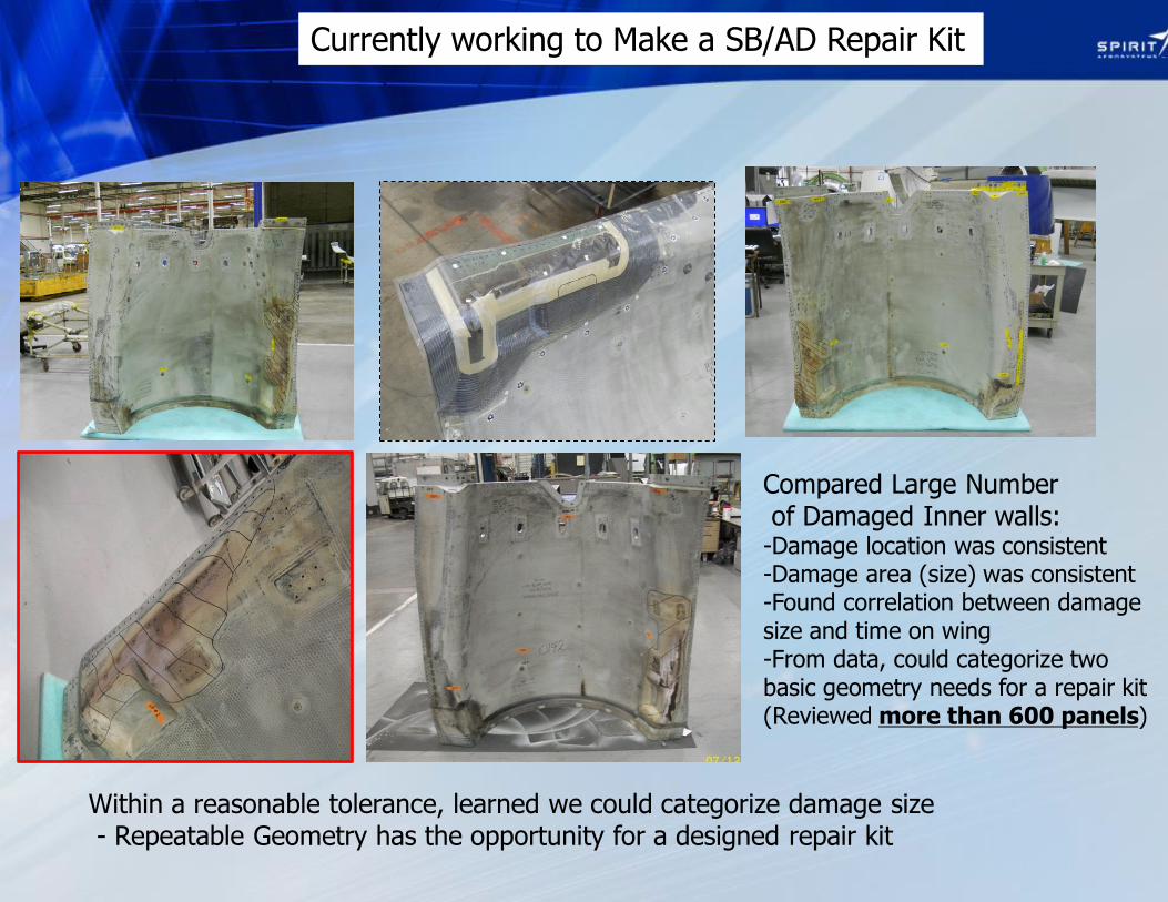
Currently working to Make a SB/AD Repair Kit
Compared Large Number of Damaged Inner walls: -Damage location was consistent -Damage area (size) was consistent -Found correlation between damage size and time on wing -From data, could categorize two basic geometry needs for a repair kit (Reviewed more than 600 panels)
Within a reasonable tolerance, learned we could categorize damage size - Repeatable Geometry has the opportunity for a designed repair kit
13 of 32
© 2010 Spirit AeroSystems, Inc. All Rights Reserved Non-Technical Data ECCN: EAR99
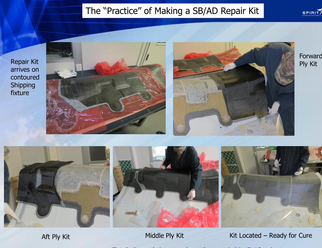
The “Practice” of Making a SB/AD Repair Kit
Repair Kit arrives on contoured Shipping fixture
Forward Ply Kit
Aft Ply Kit Middle Ply Kit Kit Located – Ready for Cure
Total elapsed time to place the repair kit, 7-12 minutes
© 2010 Spirit AeroSystems, Inc. All Rights Reserved Non-Technical Data ECCN: EAR99
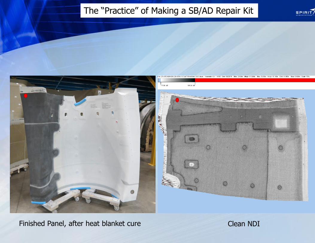
The “Practice” of Making a SB/AD Repair Kit
Finished Panel, after heat blanket cure Clean NDI
© 2010 Spirit AeroSystems, Inc. All Rights Reserved Non-Technical Data ECCN: EAR99
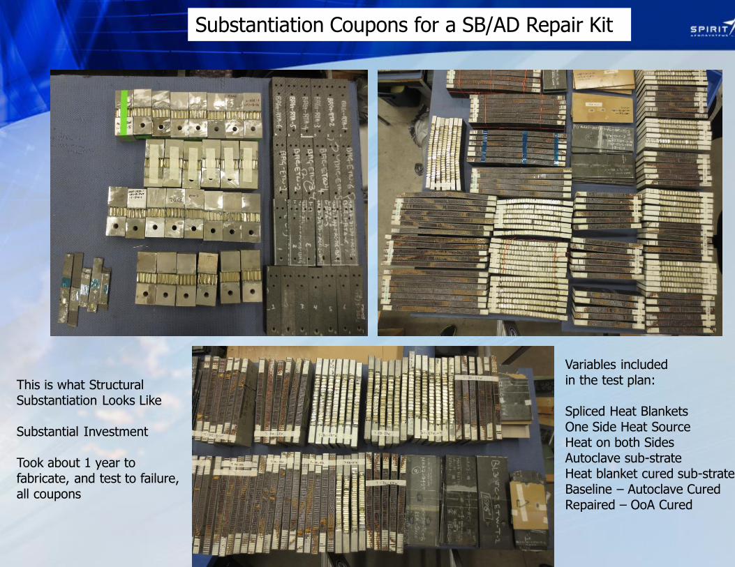
Substantiation Coupons for a SB/AD Repair Kit
This is what Structural Substantiation Looks Like Substantial Investment Took about 1 year to fabricate, and test to failure, all coupons
Variables included in the test plan: Spliced Heat Blankets One Side Heat Source Heat on both Sides Autoclave sub-strate Heat blanket cured sub-strate Baseline – Autoclave Cured Repaired – OoA Cured
© 2010 Spirit AeroSystems, Inc. All Rights Reserved Non-Technical Data ECCN: EAR99
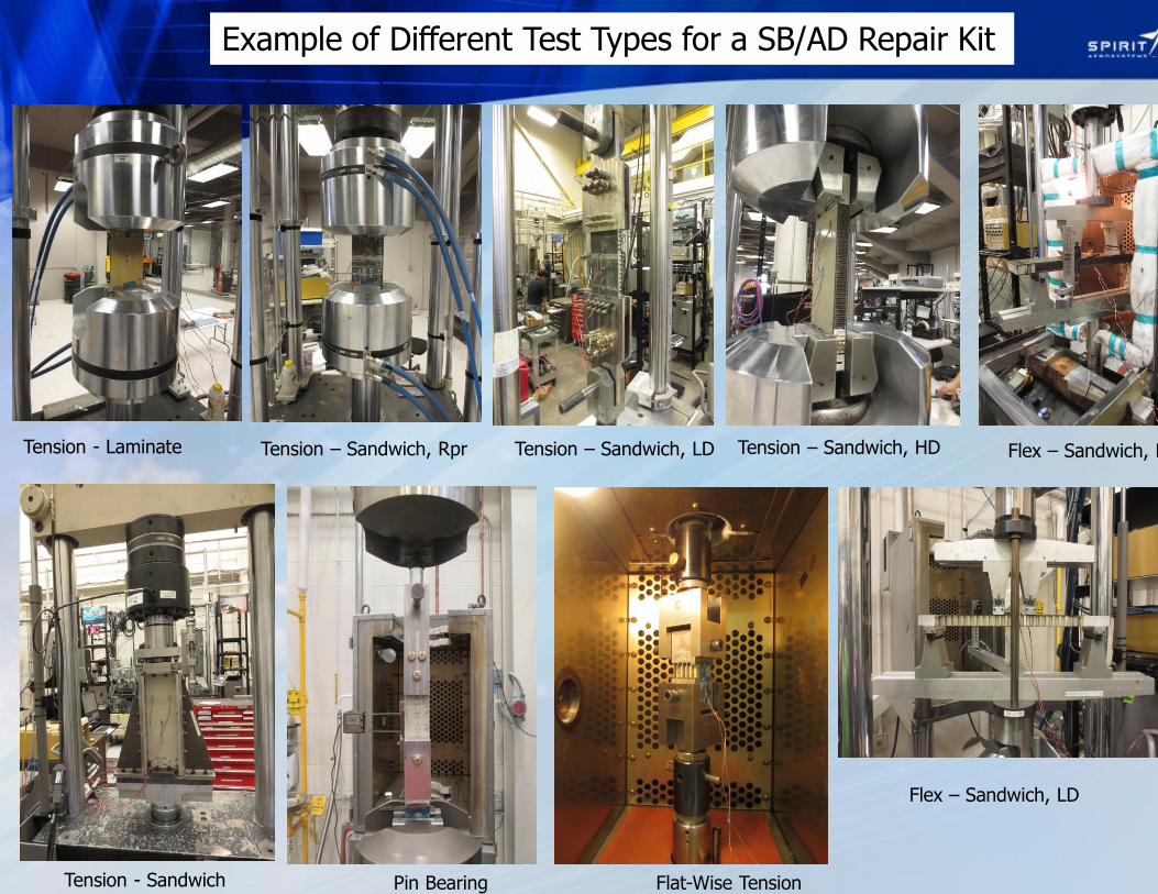
Example of Different Test Types for a SB/AD Repair Kit
Tension - Laminate Tension – Sandwich, Rpr Tension – Sandwich, LD Flex – Sandwich, HD Tension – Sandwich, HD
Flex – Sandwich, LD
Tension - Sandwich Pin Bearing Flat-Wise Tension
© 2010 Spirit AeroSystems, Inc. All Rights Reserved Non-Technical Data ECCN: EAR99
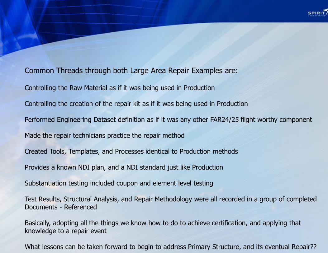
Common Threads through both Large Area Repair Examples are: Controlling the Raw Material as if it was being used in Production Controlling the creation of the repair kit as if it was being used in Production Performed Engineering Dataset definition as if it was any other FAR24/25 flight worthy component Made the repair technicians practice the repair method Created Tools, Templates, and Processes identical to Production methods Provides a known NDI plan, and a NDI standard just like Production Substantiation testing included coupon and element level testing Test Results, Structural Analysis, and Repair Methodology were all recorded in a group of completed Documents - Referenced Basically, adopting all the things we know how to do to achieve certification, and applying that knowledge to a repair event What lessons can be taken forward to begin to address Primary Structure, and its eventual Repair??

© 2010 Spirit AeroSystems, Inc. All Rights Reserved Non-Technical Data ECCN: EAR99
Adhesive Bond Strength Dependence On Process Evidenced
By CACRC Round Robin
• DOT/FAA/AR-03/74, February 2004
16
Cure error reported after test results reported
Courtesy Michael Borgman, Nov 2014 FAA workshop Bonded Repair Initiative

© 2010 Spirit AeroSystems, Inc. All Rights Reserved Non-Technical Data ECCN: EAR99
2014 FAA/CACRC Round Robin Study
CACRC = Commercial Aircraft Composites Repair Committee,
SAE/International
17
Ba
se
lin
e (n
o re
pa
ir)
NIA
R
De
po
t 1
De
po
t 2
De
po
t 3
De
po
t 4
Repair S
trength
2014 evidence of inconsistent repair structural performance across repair depots
(lowest results show only 68% strength restoration)
Courtesy Michael Borgman, Nov 2014 FAA workshop Bonded Repair Initiative

© 2010 Spirit AeroSystems, Inc. All Rights Reserved Non-Technical Data ECCN: EAR99
AMC 25.571(a), (b) and (e) Damage Tolerance and Fatigue Evaluation of Structure
• Principal Structural Elements
18
Courtesy Michael Borgman, Nov 2014 FAA workshop Bonded Repair Initiative

© 2010 Spirit AeroSystems, Inc. All Rights Reserved Non-Technical Data ECCN: EAR99
AMC 25.571(a), (b) and (e) Damage Tolerance and Fatigue Evaluation of
Structure • The damage-tolerance evaluation of
structure is intended to ensure that
should serious fatigue, corrosion, or
accidental damage [manufacturing
defects] occur within the operational life
of the aeroplane, the remaining structure
can withstand reasonable loads without
failure or excessive structural deformation
until the damage is detected.
Courtesy Michael Borgman, Nov 2014 FAA workshop Bonded Repair Initiative

© 2010 Spirit AeroSystems, Inc. All Rights Reserved Non-Technical Data ECCN: EAR99
AMC 20-29 (AC 20-107B)
Building Block Test Protocol
• Building block approach recommended for
proof of structure mechanical testing (when
additional tests required)
20
Courtesy Michael Borgman, Nov 2014 FAA workshop Bonded Repair Initiative
© 2010 Spirit AeroSystems, Inc. All Rights Reserved Non-Technical Data ECCN: EAR99
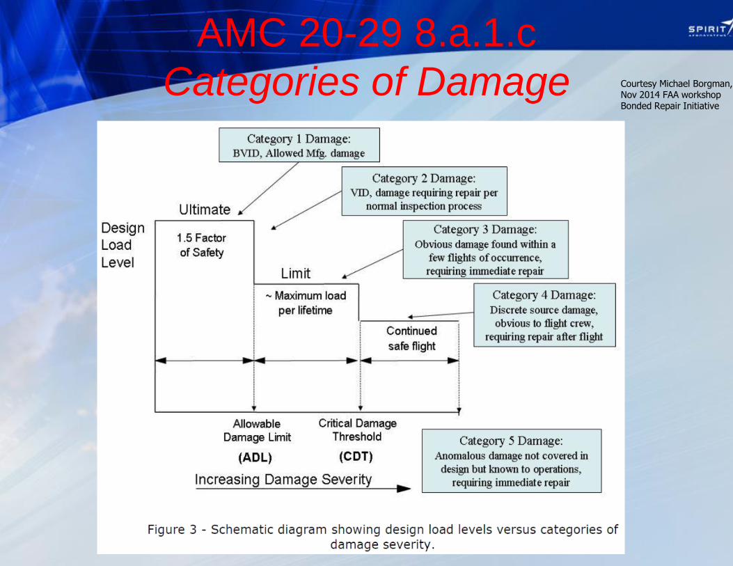
AMC 20-29 8.a.1.c
Categories of Damage Courtesy Michael Borgman, Nov 2014 FAA workshop Bonded Repair Initiative

© 2010 Spirit AeroSystems, Inc. All Rights Reserved Non-Technical Data ECCN: EAR99
AMC 20-29 (AC 20-107B) 6.b Design Considerations for Manufacturing
Implementation • Process specifications and manufacturing documentation for composite fab & assy.
• Facilities environment and cleanliness must be controlled to qualification validated level.
• Raw and ancillary materials controlled to specifications consistent with qualifications.
• Parts fabricated meet production tolerances validated in qualification, design, and proof tests.
• Key process considerations include: – (i) material handling and storage, (ii) laminate layup and bagging, (iii) mating part dimensional
tolerance control, (iv) part cure (thermal management), (v) machining and assembly, (vi) cured part inspection and handling procedures, and (vii) technician training for specific material, processes, tooling and equipment.
• Substantiating data needed for all known defects, damage and anomalies allowed without rework.
– Manufacturing records support identification and substantiation of known defects, damage and anomalies.
• New substantiating data is needed from new suppliers of parts previously certificated. – May be supported by manufacturing trials and quality assessments to ensure equivalent
production and repeatability
– Some destructive inspection of critical structural details is needed for manufacturing flaws not end item inspect-able.
Courtesy Michael Borgman, Nov 2014 FAA workshop Bonded Repair Initiative

© 2010 Spirit AeroSystems, Inc. All Rights Reserved Non-Technical Data ECCN: EAR99
• BRSL requires substantiation for two scenarios :
1. Repair bond intact (“patch on”) = Ultimate
capable
2. Repair bond failed (“patch off”) = Limit
Capable
23
1) Repair intact 2) Repair failed
Limit X X
Ultimate X ---
X Y
X Y
X Y
X = basis airframe TC requirements
Y = requirements defined during repair substantiation and approval process
BRSL - implied substantiation requirements
Strength & Deformation
Damage tolerance
Durability
Environmental resilience
BRSL results in more complex substantiation task (2 step process instead of 1 step)
Bonded Repair Size Limits Policy
Implications Courtesy Michael Borgman, Nov 2014 FAA workshop Bonded Repair Initiative
© 2010 Spirit AeroSystems, Inc. All Rights Reserved Non-Technical Data ECCN: EAR99
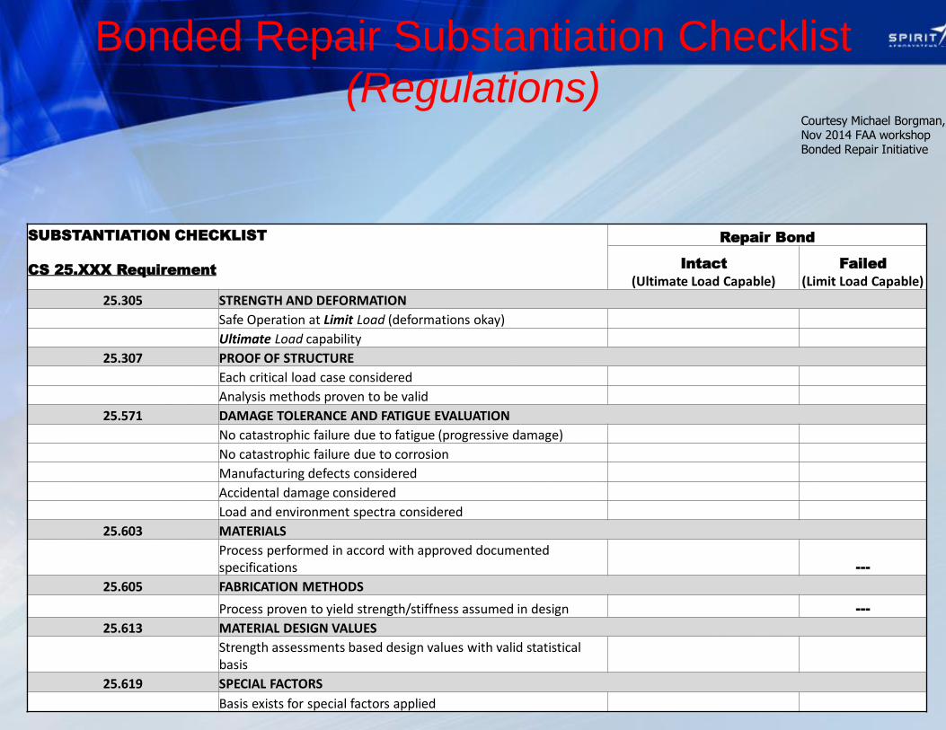
Bonded Repair Substantiation Checklist
(Regulations)
SUBSTANTIATION CHECKLIST
CS 25.XXX Requirement
Repair Bond
Intact
(Ultimate Load Capable) Failed
(Limit Load Capable)
25.305 STRENGTH AND DEFORMATION
Safe Operation at Limit Load (deformations okay)
Ultimate Load capability
25.307 PROOF OF STRUCTURE
Each critical load case considered
Analysis methods proven to be valid
25.571 DAMAGE TOLERANCE AND FATIGUE EVALUATION
No catastrophic failure due to fatigue (progressive damage)
No catastrophic failure due to corrosion
Manufacturing defects considered
Accidental damage considered
Load and environment spectra considered
25.603 MATERIALS
Process performed in accord with approved documented specifications ---
25.605 FABRICATION METHODS
Process proven to yield strength/stiffness assumed in design ---
25.613 MATERIAL DESIGN VALUES
Strength assessments based design values with valid statistical basis
25.619 SPECIAL FACTORS
Basis exists for special factors applied
Courtesy Michael Borgman, Nov 2014 FAA workshop Bonded Repair Initiative

© 2010 Spirit AeroSystems, Inc. All Rights Reserved Non-Technical Data ECCN: EAR99
Bonded Repair Substantiation Checklist
(Guidance)
SUBSTANTIATION CHECKLIST
Guidance
Repair Bond
Intact
(Ultimate Load Capable) Failed
(Limit Load Capable)
CS-25 Book 2 AMC 25.307
Proof of structure by analysis supported by existing test evidence, or
Proof of structure by analysis supported by new test evidence, or
Proof of structure by Test Only
Limitations of stress analysis method understood
Conservative stress analysis assumptions used to compensate for limited test evidence
CS-25 Book 2 AMC 25.571
If repair bond fails residual structure can withstand reasonable loads until failure detected
Part is Principal Structural Element
Bond failure detection strategy and corresponding special inspections and intervals defined
CS-25 Book 2 AMC 25.613
Repair M&P aligns with M&P used in design value development (or equivalency established)
Mechanical test specimens conform to universally accepted standard
Effects of temperature and moisture taken into account in design values development
AC 21-26A
"Quality System" employed in repair materials and processes controls
Inspection standards exist for NDI acceptance tests
Inspection standards exist for DI acceptance tests
inspection standards exist for visual inspections
Geometric inspection performed to confirm compliance with engineering requirements
AMC 20-29
All Materials & Processes qualified by manufacturing trials and appropriate testing
Surface preparation performed in accord with process qualification or approved data
Mechanical tests for proof of structure performed at appropriate levels of building block
Bond failure detection strategy and corresponding special inspection intervals and protocol defined
Bonded Repair Size Limits Policy Memo
Repair size no larger than size allowing LIMIT LOAD residual strength with repair failed within constraints of arresting design features
Courtesy Michael Borgman, Nov 2014 FAA workshop Bonded Repair Initiative
© 2010 Spirit AeroSystems, Inc. All Rights Reserved Non-Technical Data ECCN: EAR99
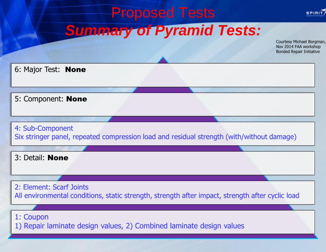
Proposed Tests
Summary of Pyramid Tests:
1: Coupon 1) Repair laminate design values, 2) Combined laminate design values
2: Element: Scarf Joints All environmental conditions, static strength, strength after impact, strength after cyclic load
3: Detail: None
4: Sub-Component Six stringer panel, repeated compression load and residual strength (with/without damage)
5: Component: None
6: Major Test: None
Courtesy Michael Borgman, Nov 2014 FAA workshop Bonded Repair Initiative

© 2010 Spirit AeroSystems, Inc. All Rights Reserved Non-Technical Data ECCN: EAR99
Summary, The Challenge of Primary Structure and necessary Repair Substantition
• Examples of capable and responsible repair techniques and methods that prove to be restorative to the original mission have been examined throughout this workshop. It is also impossible to ignore the variation that has been witnessed from the 2004 CACRC Round Robin test effort, to the 2014 test effort of the same ilk (different coupon types), as well as examples of repairs in the fleet that simply did not work.
• One thing that can be concluded, is that the components of repeated Large Area repair efforts that have been proven successful, followed techniques more common to complying to FARs 23,24,25,26, 33, 34 or 36, than to MRO efforts that comply to FARs 43 and 145. Observation only.
• For Primary Structure applications that one day can be universally accepted for composite repair techniques, it may have to be recognized that repair methods and techniques more closely resembling Production Processes, are a necessary avenue to gaining wide spread repair method, materials, and technique acceptance.
• There has been some very good work done to lay the ground work for how to perform potential Primary Structure composite repairs, however, a great deal of substantiation testing remains for all. It looks like a good game plan, we should stick with it, follow it, and improve it where needed.
• Some innovation in surface preparation, newer, higher strength (and strain) adhesive formulations, and exploration into techniques that have worked on other structure to see if they apply to Primary Structure, would assist in gaining more traction for future PSE composite repair “acceptance.”
• It would be very helpful, and truly desired to arrive at a unified position of what constitutes “substantiation”, and methods to go about achieving it.
• Training is an important facet to continue to explore. The author feels “practice” as part of a training or certifying event is also a key factor to actually being able to have a controlled repair process.
• The need to repair commercial transport composite Primary Structure will not go away. The need to repair and return
to service damage sizes that are greater than those identified by Bonded Repair Size Limits will also exist. Without continued efforts to research and find solutions of this nature, the future maintenance challenges of all composite aircraft may deem that material choice “negative” from a business or dispatch perspective. We need to continue to find a way to repair, capably, Primary Structure.
John M. Welch
Top Related