


Languages
Pages
Legal


Environment Protection Authority
EPA Protocols: Compliance testing of dental X-ray apparatus used for plain radiography
Doc. No. RP91

EPA Protocols: Compliance testing of dental X-ray apparatus used for plain radiography
Prepared by the Radiation Protection Branch
For further information please contact:
Information Officer
Environment Protection Authority
GPO Box 2607
Adelaide SA 5001
Telephone: (08) 8204 2004
Facsimile: (08) 8124 4670
Free call (country): 1800 623 445
Website: <www.epa.sa.gov.au>
Email: <[email protected]>
ISBN 978-1-921125-96-9
Issued June 2009
Updated April and December 2011
Disclaimer
This publication is a guide only and does not necessarily provide adequate information in relation to every situation. This
publication seeks to explain your possible obligations in a helpful and accessible way. In doing so, however, some detail
may not be captured. It is important, therefore, that you seek information from the EPA itself regarding your possible
obligations and, where appropriate, that you seek your own legal advice.
© Environment Protection Authority
This document may be reproduced in whole or part for the purpose of study or training, subject to the inclusion of an
acknowledgment of the source and to it not being used for commercial purposes or sale. Reproduction for purposes other
than those given above requires the prior written permission of the Environment Protection Authority.

Table of contents
Abbreviations ......................................................................................................................................................................1
Definitions............................................................................................................................................................................2
1 Introduction ...................................................................................................................................................................3
1.1 Purpose ...............................................................................................................................................................3
1.2 Scope ..................................................................................................................................................................3
1.3 Conventions.........................................................................................................................................................3
1.4 Precautions and limitations..................................................................................................................................3
1.5 Test instruments ..................................................................................................................................................4
1.6 Modifying an apparatus .......................................................................................................................................4
1.7 Test equipment....................................................................................................................................................4
1.8 Documentation ....................................................................................................................................................4
2 Test protocol .................................................................................................................................................................6
2.1 Owner details.......................................................................................................................................................6
2.2 Apparatus details .................................................................................................................................................6
2.3 Tester information................................................................................................................................................6
2.4 Test instrument information .................................................................................................................................6
2.5 Stationary tube* ...................................................................................................................................................7
2.6 Open ended collimator ........................................................................................................................................7
2.7 Beam limiting device* ..........................................................................................................................................7
2.8 Exposure light* ....................................................................................................................................................8
2.9 Audible signal*.....................................................................................................................................................8
2.10 Control panel lights* ............................................................................................................................................9
2.11 Radiation shield (hand held only)† .......................................................................................................................9
2.12 Log book (hand held only)† ..................................................................................................................................9
2.13 Dead man switch ...............................................................................................................................................10
2.14 Exposure termination* .......................................................................................................................................10
2.15 Timer reset ........................................................................................................................................................11
2.16 Zero timer setting* .............................................................................................................................................11
2.17 Trial exposure* ..................................................................................................................................................11
2.18 Control parameters............................................................................................................................................12
2.19 Mains switch and indicator ................................................................................................................................12
2.20 Focal spot ..........................................................................................................................................................13
2.21 Multiple tubes ....................................................................................................................................................13
2.22 ‘Radiation Produced When Energised’ sign*.....................................................................................................14
2.23 ‘Radiation Area’ sign* ........................................................................................................................................14
2.24 Good working order*..........................................................................................................................................15
2.25 Consistency*......................................................................................................................................................15
2.26 Half value layer* ................................................................................................................................................15
2.27 Tube voltage......................................................................................................................................................16

2.28 Linearity .............................................................................................................................................................17
2.29 Beam size* ........................................................................................................................................................17
2.30 Leakage.............................................................................................................................................................18
2.31 Operator protection* ..........................................................................................................................................18
2.32 Shielding* ..........................................................................................................................................................20
3 References...................................................................................................................................................................22
Annex 1 Radiation signs..........................................................................................................................................23
List of figures
Figure 1 Operator position...............................................................................................................................................19
Figure 2 Radiation Produced When Energised ...............................................................................................................23
Figure 3 Radiation symbol...............................................................................................................................................23
Figure 4 Radiation symbol plus radiation warning...........................................................................................................23
List of tables
Table 1 Minimum HVL (in mm of Al) for various set kVp................................................................................................16

1
Abbreviations
General
Al aluminium
ALARA as low as reasonably achievable
CR computed radiography
DR direct radiography
EPA Environment Protection Authority
HVL half value layer
min minimum
TPC Third Party Certification
Units and parameters
A Ampere
Gy Gray
h hour
lx lux
m metre
s seconds
Sv Sievert
Vp volts peak
Prefixes
n nano (10-9)
µ micro (10-6)
m milli (10-3)
c centi (10-2)
k kilo (103)
2
Definitions
Fixed apparatus means any apparatus that is neither a mobile apparatus nor a portable apparatus. This includes any
mobile apparatus that has been modified in such a manner so that it can no longer be moved from place to place or a
portable apparatus that has been modified in such a manner so that it can no longer be carried manually from place to
place.
Fixed protective barrier means a barrier that cannot be readily removed and has a lead equivalence of 0.15 mm.
Mobile apparatus means apparatus that is designed and constructed so as to be moveable from place to place for use
as required but does not include a portable apparatus.
Portable apparatus means any apparatus that is designed to be carried manually from place to place for use as
required.
Hand held apparatus means any apparatus that is designed and constructed so as to be used while held by the
operator.
EPA Protocols: Compliance testing of dental X-ray apparatus used for plain radiography
1 Introduction
1.1 Purpose
This document details the protocol for conducting compliance testing of plain dental X-ray apparatus which includes fixed,
mobile and portable apparatus. It also includes apparatus that are used in a hand held manner. It does not include
orthopantomographic, cephalometric or computed tomography apparatus.
1.2 Scope
The testing is performed in order to satisfy the legislative requirements of the Radiation Protection and Control Act 1982
(the RPC Act) and the Radiation Protection and Control (Ionising Radiation) Regulations 2000 (the Regulations) and can
only be performed by persons authorised by the Environment Protection Authority (EPA). Such persons consist of
Authorised Officers under the Act and those accredited under the Third Party Certification (TPC) program1 administered
by the EPA.
1.3 Conventions
Throughout this document labelled text is used to indicate additional information as discussed below.
Important Note Important information for the attention of the tester.
Tip Indicates that additional information is provided to assist in the interpretation of the relevant test.
Tolerance Some tests have a tolerance that can be applied to the measured result. This is to allow for potential errors
in measurements. Tolerances are added and/or subtracted from the regulatory limits as indicated.
* Some older apparatus may have been registered before 1 April 1986 under the Radioactive Substances and Irradiating
Apparatus Regulations 1962 and as such need only fulfill the requirements of sections indicated with an asterisk (*).
However, testers must still perform all tests and evaluate each one for compliance. The EPA will assess overall
compliance of older apparatus prior to registration.
† Denotes that this test applies only to an apparatus that is used in a hand held manner. Note that the owner must have
an exemption from regulation to use an apparatus in a hand held manner.
1.4 Precautions and limitations
Image receptors
Before any X-ray apparatus is energised ensure that any radiographic film or imaging plate is located well away from the
X-ray apparatus, so as to avoid possible exposure to X-rays.
Personal radiation monitoring device
Ensure an appropriate personal radiation monitoring device is placed on your person prior to commencement of testing.
For further information on these devices see EPA Guidelines—Personal radiation monitoring devices.
1 Information regarding the TPC program is contained in the document EPA Guidelines—Program requirements for
compliance testing of diagnostic X-ray apparatus.
3

EPA Protocols: Compliance testing of dental X-ray apparatus used for plain radiography
1.5 Test instruments
Testing for compliance requires non-invasive measurements of radiation output, tube voltage, exposure time, and half
value layer (HVL) of the primary X-ray beam and any radiation that might be present due to the leakage from the X-ray
tube housing. The shielding effectiveness of a protective barrier is determined by means of radiation transmission
measurements.
To cater for the different requirements, test instruments come in variety of types and measure a variety of parameters,
depending on the type and model. Broadly they can be divided into having ionisation chambers, or one or more
semiconductor detectors. In particular the sensitivity (the lowest measurable dose) of instruments varies and for some
measurements (ie shielding and leakage) doses in the µGy or nGy ranges may be required.
Measurement of HVL can be performed directly by some instruments and indirectly by others—by means of dose
measurements with and without added aluminium (Al) filters placed in the primary beam. With this in mind, testers should
ensure that the instruments they are using are appropriate to the task.
1.6 Modifying an apparatus
An apparatus must be compliance tested in the condition in which it has been installed and will be used. Testers must not
add any additional equipment (eg mains voltage conditioners) to the apparatus during compliance testing.
1.7 Test equipment
The following test equipment may be required:
radiation meter/detector
Al filters as required (≥ 99% purity)
image receptor (occlusal dental film or equivalent)
lead block - 1 mm thick (minimum) x 65 mm (minimum) x 65 (minimum)
tape measure (at least 5 m is recommended)
vernier callipers or accurate ruler
photographic developing facility (eg darkroom, chemicals, processing tank, etc)
masking tape or equivalent.
1.8 Documentation
Test Report
For each apparatus tested the results must be documented in the form of a Test Report, a copy of which must be
provided to the owner of the apparatus within 14 days of the date of testing.
The preparation of the Test Report is the responsibility of the accredited tester. The form and style of the report is at the
discretion of the tester but results must be clear and accurate.
Note that, accredited testers need not routinely provide the EPA with Test Reports. However the EPA may request a
copy of a report at any time.
4

EPA Protocols: Compliance testing of dental X-ray apparatus used for plain radiography
Compliance Statement
For each apparatus tested the tester must indicate the compliance status of the apparatus or the area in which it is
installed by indicating either a ‘Yes’ (compliant), ‘No’ (not compliant) or ‘N/A’ (not applicable) on the appropriate
Compliance Statement.
Testers must provide a Compliance Statement to the EPA using the prescribed form within 14 days of the date of testing.
Posted and electronic copies (ie email and facsimile) are accepted. If submitting a statement via email or facsimile you
need not also submit the original by post.
The following Compliance Statements are applicable to the protocols of this document:
Compliance Statement (Form 91A)—Dental X-ray apparatus used for plain radiography.
5

EPA Protocols: Compliance testing of dental X-ray apparatus used for plain radiography
2 Test protocol
This test protocol must be followed by all personnel performing compliance testing. Information and results, as specified
in this section, must be recorded in the Test Report.
Important Note
The tests specified in this protocol use non-invasive methods and do not require the tester to remove, modify or
otherwise interfere with any part of an apparatus or structure relating to the environment in which the apparatus is
installed.
The consistency test (refer section 2.25) must be the first test performed for which the X-ray tube is to be energised.
This ensures that results are reflective of a tube that is operated from cold. All other tests can be performed in an
order at the discretion of the tester.
2.1 Owner details
Record the name, address, and contact details (phone number and/or email address) of the client. Note: the client can be
a person and/or a business.
2.2 Apparatus details
Make & model: record the full make and model of the apparatus.
Generator/controller serial number: record the serial number of the X-ray generator/controller unit of the apparatus. If
the serial number label is not present on the apparatus, simply record as ‘unknown’.
Tube serial number: record the serial number of the X-ray tube of the apparatus. If the serial number label is not present
on the apparatus, simply record as ‘unknown’.
Tube housing serial number: record the serial number of the X-ray tube’s housing of the apparatus. If the serial number
label is not present on the apparatus, simply record as ‘unknown’.
Apparatus location: record the room name or number (eg Surgery 1) in which the apparatus is located.
Filtration (mm of Al): an X-ray tube will have an inherent filtration built into the tube itself and possibly additional filtering
added to the tube housing. The material used is generally aluminium, though other materials (eg copper) are possible.
Record the filtration expressed in the appropriate unit (eg mm of Al).
2.3 Tester information
Contact details: record the name, address, and contact details (phone number and/or email address) of the person
conducting the compliance test.
Test date(s): record the date or dates on which the tests are performed.
2.4 Test instrument information
Meter/detector: record the make and model of the instrument’s meter and its detector.
Tip Test instruments can consist of a single module, such as an ionisation chamber and a meter read-out in one.
Alternatively they may have separate detectors (eg ionisation chamber and kVp sensor) connected to a meter. Record
the make and model of all modules used.
6

EPA Protocols: Compliance testing of dental X-ray apparatus used for plain radiography
Serial Numbers: record the serial number or numbers of the instrument’s meter and detector. If not known simply record
as ‘unknown’.
Calibration: all test instruments used must be calibrated at least once every two years to ensure that measurement
accuracy is maintained. Record the date the last time a calibration of the instrument was performed.
2.5 Stationary tube*
Purpose
To eliminate the possibility of the tube moving once it has been correctly positioned. This minimises the possibility of
retakes and of an unnecessary exposure of radiation to the patient.
Method
Place the tube housing in positions that would be typically used in dental radiography. For each position visually check
whether or not the tube head moves.
Requirement
The tube housing must remain stationary.
Compliance reference
Regulation 91(3).
2.6 Open ended collimator
Purpose
To ensure that the apparatus is fitted with the correct style of beam limiting device.
Method
Visually examine the collimator (ie cone).
Requirement
The collimator must be open ended.
Compliance reference
Regulation 91(5).
2.7 Beam limiting device*
Purpose
To ensure the length of the beam limiting device (ie cone) is sufficient to limit the radiation dose to the patient.
Tip The cone length, in part, determines the source-to-skin distance and hence the skin entrance dose the patient
receives. The amount of scattered radiation is also reduced by the presence of a cone.
7

EPA Protocols: Compliance testing of dental X-ray apparatus used for plain radiography
Method
The focal spot is indicated on the tube housing usually by a small dot or square. Measure the distance from the focal spot
(in mm) to the end of the cone.
Requirement
For an apparatus first registered after 1 April 1986 the minimum distance from the outer end of the cone to the focal point
of the X-ray tube must be at least 200 mm. For apparatus first registered before 1 April 1986 this distance is 100 mm.
Compliance reference
Regulation 91(6).
2.8 Exposure light*
Purpose
To ensure that the operator is given a visual warning that the X-ray tube is energised.
Method
Energise the X-ray tube and take note of any visual warning signals. Note the colour of the warning signal.
Requirement
A red or amber light must be incorporated into the apparatus to indicate that the X-ray tube is energised.
Tip If an apparatus was first registered before 1 April 1986 it only needs to comply with this test; but only when it does
not comply with the Audible Signal test in section 2.9.
Compliance reference
Regulation 91(8)(a).
2.9 Audible signal*
Purpose
To ensure there is an audible warning that the X-ray tube is energised.
Method
Energise the X-ray tube and take note of any audible warning signals.
Requirement
An audible signal must be incorporated into the apparatus to indicate that the X-ray tube is energised.
Tip If an apparatus was first registered before 1 April 1986 and it complies with this test it need not comply with the
‘Exposure Light’ test in section 2.8 and the Control Panel Lights test in section 2.10.
Compliance reference
Regulation 91(8)(b).
8
EPA Protocols: Compliance testing of dental X-ray apparatus used for plain radiography
2.10 Control panel lights*
Purpose
To ensure the operator has a clear and visible indication that X-rays are being produced.
Method
Take note of the colour of any lights present on the controller of the apparatus.
Requirement
The lights on the controller must not be the same as the exposure light in section 2.8.
Tip If an apparatus was first registered before 1 April 1986 it only needs to comply with this test; but only when it does
not comply with the Audible Signal test in section 2.9.
Compliance reference
Regulation 91(9).
2.11 Radiation shield (hand held only)†
Important Note This test applies only to the NOMAD Portable X-Ray apparatus. For an owner to use an apparatus in a
hand held manner requires and exemption from regulation. Testers are advised to contact the EPA for advice.
Purpose
To ensure that a radiation shield is fitted to the apparatus and that it cannot be removed from the cone.
Method
Inspect the shield and note if the shield is capable of being detached from the end of the cone.
Requirement
The shield must be located near the end of the cone and must not be capable of being detached. A shield that slides
along the cone is permissible.
Compliance reference
Registration Condition 1002(3).
2.12 Log book (hand held only)†
Important Note This test applies only to the NOMAD Portable X-Ray apparatus. For an owner to use an apparatus in a
hand held manner requires and exemption from regulation. Testers are advised to contact the EPA for advice.
Purpose
To ensure that appropriate information is kept to provide a reference for any radiation exposure related issues.
Method
Inspect the log book to ensure the required information is being kept.
9

EPA Protocols: Compliance testing of dental X-ray apparatus used for plain radiography
Requirement
A log record shall be maintained for each apparatus, containing at least the following information:
the date of the radiographic procedure
the name of the person taking a radiograph
the location of the radiographic procedure
the name and identification number of the patient
the number of radiographs taken
the exposure time
the configuration of the apparatus (ie a hand held or on a stand).
Compliance reference
Registration Condition 1002(7).
2.13 Dead man switch
Purpose
To ensure that an X-ray exposure will terminate when the exposure switch is released. This is known as the dead man
function.
Method
Position the dose meter under the cone. Set the exposure time to at least 0.5 s and press the exposure switch. Release it
prior to the end of the exposure time.
Requirement
The X-ray apparatus must stop producing radiation when the exposure switch is released. This can be verified by
checking that the measured dose is less than for the full exposure.
Compliance reference
Regulation 91(13).
2.14 Exposure termination*
Purpose
To ensure that an operator can energise the X-ray tube for no longer than is set by the timer of the apparatus.
Method
This can be tested in the course of doing other measurements (eg Consistency, Linearity, etc). Simply confirm that the
apparatus has a timer that after the period defined by the timer’s settings terminates the exposure.
Requirement
A timer must be provided that, after the period defined by the timer’s setting, terminates the exposure either by a set
exposure time or by the product of its tube current and exposure time (ie mAs).
10

EPA Protocols: Compliance testing of dental X-ray apparatus used for plain radiography
Compliance reference
Regulation 91(14).
2.15 Timer reset
Purpose
To ensure that, after an exposure has been taken, there is no possibility that the X-ray tube can be energised for a period
differing from what was initially set by the operator.
Method
This can be tested in the course of doing other measurements (eg Consistency, Linearity, etc). Confirm that when an
exposure is taken, the timer resets itself to its initial setting or zero.
Requirement
When an exposure terminates the timer must automatically reset to its initial setting or to zero.
Compliance reference
Regulation 91(14)(a).
2.16 Zero timer setting*
Purpose
To ensure that there is no possibility that an operator can energise the X-ray tube when the timer of the apparatus is set
to zero.
Method
If the timer has a zero setting, select that time. Position the dose meter under the primary beam and press the exposure
switch. Note whether or not there was any audible signal, visual warning or dose meter reading.
Requirement
It must not be possible to energise the X-ray tube if the timer is set to zero. Note: if the timer does not have a zero setting
then the apparatus is considered compliant with this regulation.
Compliance reference
Regulation 91(14)(b).
2.17 Trial exposure*
Purpose
To ensure that the operator is not required to make a trial exposure (as that would be an unnecessary exposure of
radiation to the patient) to establish the correct tube voltage, tube current or exposure time.
11

EPA Protocols: Compliance testing of dental X-ray apparatus used for plain radiography
Method
Confirm (for an apparatus with variable tube voltage, tube current or exposure time) the apparatus can have its tube
voltage, tube current or exposure time set such that it does not require a trial exposure.
Requirement
If an apparatus is capable of having its tube voltage, tube current or exposure time settings varied these control settings
must not require a trial exposure in order to set them.
Compliance reference
Regulation 91(15)(a).
2.18 Control parameters
Purpose
To ensure that an exposure of radiation to the patient or operator is set by control parameters (kVp, mA and exposure
time) whose values are accurately reflected by the labelling on the apparatus. This allows the operator to be fully
informed of the nominal values of the control parameters.
Method
Confirm, for an apparatus with fixed control parameters (ie kVp, mA or exposure time), a label is affixed to the tube
housing or control panel indicating the values.
Tip kVp must be measured to confirm that it accurately reflects displayed values. Refer section 2.27 for details.
Requirement
If an apparatus has fixed kVp, mA or exposure time, the apparatus must have labels affixed to its tube housing or control
panel indicating the value of these control parameters.
Compliance reference
Regulation 91(15)(b).
2.19 Mains switch and indicator
Purpose
To ensure that when only the mains power is applied to the apparatus the X-ray tube is not automatically energised and
that the operator can clearly see that the apparatus has mains power applied to it by means of an indicator light or lights.
Method
Note whether or not the apparatus has a mains switch fitted that only controls the supply of mains to the apparatus and
that there is some form of indicator alight when the mains power is applied.
Requirement
The apparatus must have a mains switch fitted that only controls the supply of mains power to the apparatus and there
must be a visual indication the mains is in the ‘ON’ position.
12

EPA Protocols: Compliance testing of dental X-ray apparatus used for plain radiography
Tip the mains indicator light need not be a dedicated light and can include indicators such as a digital display or similar.
Compliance reference
Regulation 91(16).
2.20 Focal spot
Purpose
To ensure that the position of the focal point of the X-ray tube is known.
Method
Note whether or not the focal spot is clearly indicated on the X-ray tube housing.
Requirement
The position of the focal spot must be clearly indicated on the X-ray tube housing.
Tip The precise location of the X-ray tube’s focal point is not often known, but is usually indicated near or at the centre
of the tube’s housing. However if there is no focal spot indicated or the spot is not sufficiently clear, the apparatus is not
considered compliant with the relevant regulation.
Compliance reference
Regulation 91(17).
2.21 Multiple tubes
Purpose
To ensure that if multiple X-ray tubes can be operated from a single control panel, the incorrect tube cannot be
inadvertently energised and risk the unintended radiation exposure. Note: if the apparatus only has a single tube this test
is not applicable.
Method
1. Position the dose meter under the cone on one of the X-ray apparatus under test.
2. Use the control panel to select the apparatus that will be energised. There must be indication that the correct
apparatus has been selected.
3. Press the exposure switch from the control panel. Confirm that there is any dose indicated by the meter. Note also if
the ‘tube energised’ indicator light (near the tube housing) of the relevant apparatus is illuminated.
4. Repeat for any other X-ray tubes that are operated from the control panel.
Requirement
When more than one X-ray tube can be operated from a single control panel, it must not be possible to energise more
than one X-ray tube at the same time and there must be an indication at or near each tube housing and on the control
panel showing which X-ray tube is selected.
Compliance reference
Regulation 91(18).
13
EPA Protocols: Compliance testing of dental X-ray apparatus used for plain radiography
2.22 ‘Radiation Produced When Energised’ sign*
Purpose
Ensures that an appropriate warning sign is displayed to indicate that the apparatus will emit radiation when it is
energised.
Method
Note whether or not an appropriate sign is displayed on or near the controller of the apparatus.
Requirement
An appropriate sign is one that complies with Australian Standard 1319−1994 Safety Signs for the Occupational
Environment as it applies to warning signs. It must bear the radiation symbol, the words ‘RADIATION PRODUCED
WHEN ENERGISED’ or words to that effect, and be clearly legible at 2 m. Refer Figure 2 for an example.
Tip As some apparatus have a controller that is too small to fit the required warning label (for example a hand held
type), it can be displayed in a position that is near to where the controller is normally placed. If this is impractical, it is
acceptable to have a sign that is displayed somewhere else on the apparatus, such as its tube housing or arm.
Compliance reference
Regulation 64.
2.23 ‘Radiation Area’ sign*
Purpose
To ensure that an appropriate warning sign is displayed, at each entrance to the room, in which an X-ray apparatus is
installed (for fixed apparatus) or normally kept or used (for mobile apparatus).
Method
Confirm that an appropriate sign is displayed at or near each entrance to the room where a fixed apparatus is installed.
For a mobile apparatus a warning sign must be placed at each entrance to the room where it is normally kept or used. In
the case of an open area installation, a sign at each walkway or access route to the installation is required.
Requirement
An appropriate sign is one that complies with Australian Standard 1319−1994 Safety Signs for the Occupational
Environment as it applies to warning signs, bears the radiation symbol, has a total surface area of not less than 4500
mm2, and is clearly legible at 2 metres. In addition to the radiation symbol the sign may use wording. If this is the case, it
must bear the words ‘RADIATION AREA’ or ‘X-RAYS’ or words to that effect. Refer to Figure 3 and Figure 4 for
examples.
Tip A doorway which leads to an adjacent room (eg a storeroom, office, etc) that cannot be entered from any other
room, is not regarded as an entrance to the apparatus room and hence the relevant regulation does not apply to such an
entrance.
Compliance reference
Regulation 65.
14

EPA Protocols: Compliance testing of dental X-ray apparatus used for plain radiography
2.24 Good working order*
Purpose
To ensure that the X-ray apparatus is in good working condition.
Method
Record any abnormal performance or condition that was detected in the course of conducting the compliance tests. This
includes but is not limited to ensuring that the collimator housing is not loose, the tube housing is adequately fastened,
the exposure switch does not operate intermittently or any other abnormality that is not covered by another regulation.
Requirement
No abnormalities are detected.
Compliance reference
Regulation 9(2).
2.25 Consistency*
Important Note The measurements must be taken without any ‘warm-up’ exposures.
Purpose
To determine the consistency of radiation output so as to avoid an unnecessary variation in radiation output and therefore
an unnecessary variation in patient dose.
Method
1. Take at least five consecutive measurements of radiation output (ie dose) at a fixed tube voltage, tube current and
exposure time.
2. Calculate the coefficient of variation of the measurements of radiation output by dividing the standard deviation of the
radiation measurements by the average of the radiation measurements.
Requirement
The coefficient of variation must be less than or equal to 0.05.
Compliance reference
Regulation 91(19).
2.26 Half value layer*
Purpose
To ensure that the beam is of adequate quality so as to minimise the dose to the patient.
Method
Using dose measurements and filters
1. Insert into the beam an Al filter with a thickness greater than or equal to the thickness specified in Table 1 for
selected set kVp.
15

EPA Protocols: Compliance testing of dental X-ray apparatus used for plain radiography
2. Take an exposure and measure the radiation output at a fixed distance from the focal point.
3. Repeat the measurement but without an Al filter in the beam.
4. Calculate the transmission ratio by dividing the filtered radiation output by the unfiltered radiation output.
or direct measurement
Take an exposure and measure the HVL. Note for this method Al filters are not required.
Table 1 Minimum HVL (in mm of Al) for various set kVp
Set kVp HVL in mm of Al
30 0.3
40 0.4
49 0.5
50 1.2
60 1.3
70 1.5
71 2.1
80 2.3
Requirement
The radiation transmitted through the Al filter must be at least half the unfiltered radiation. That is, a transmission ratio ≥
0.5.
Compliance reference
Regulation 91(7).
2.27 Tube voltage
Purpose
To ensure that the indicated tube voltage, as specified on the apparatus labelling (refer section 2.18), is representative of
the measured tube voltage. A tube voltage that is too low will increase patient dose and one that is a too high can result
in poor image quality.
Method
Place the detector at the end of the cone of the apparatus. Measure the tube voltage for all set kVp values that the
apparatus is capable of generating.
Tip Some test instruments are dependent on the filtration of the apparatus and the instrument itself. To correct for
filtration, additional Al filters can be added to improve the accuracy of the measurement.
16

EPA Protocols: Compliance testing of dental X-ray apparatus used for plain radiography
Requirement
Measured tube voltages must be indicative of tube voltages shown on the apparatus labelling. Therefore, all measured
tube voltages must be within 5% (plus a tolerance) of the labelled tube voltage. If not, the X-ray apparatus may need to
be adjusted, if adjustments are possible, or relabelled.
Tolerance It is permissible to add a tolerance to a tube voltage measurement, as different test instruments measure
tube voltage in different ways affecting their relative accuracy. The EPA recommends that no more than 3% tolerance is
added. Using the ‘square root of the sum of the squares’ method provides an adequate overall tolerance. Therefore the
allowable deviation of each tube voltage is: √(52 + 32) ≈ 6%.
Compliance reference
Regulation 91(15)(b).
2.28 Linearity
Purpose
To ensure the X-ray unit generates a predictable and proportional radiation output.
Method
1. Measure the radiation output for at least five different exposure times over the range 0.1 s to 1.0 s and at any set
tube voltage. For an apparatus with a variable set tube current include at least one measurement for each tube
current.
2. Normalise the measurements by dividing each dose measurement (mGy) by the product of the set tube current (mA)
and the set exposure time (s) to obtain the ratio mGy/mAs.
3. Calculate the coefficient of variation by dividing the standard deviation of the ‘mGy/mAs’ ratios by the average of the
‘mGy/mAs’ ratios.
Requirement
The coefficient of variation must be less than or equal to 0.1.
Compliance reference
Regulation 91(20).
2.29 Beam size*
Purpose
To determine the size of the X-ray beam at the end of the beam applicator. This ensures that patient dose does not
increase unnecessarily due to an oversized beam.
Method
Tape or press the beam applicator against an image receptor and make a radiation exposure. Process the radiograph (or
equivalent) and measure the maximum dimension of the X-ray beam.
Important Note The use of fluoroscopic equipment to measure beam size may not be acceptable if the persistence of
the image is not sufficient for an accurate measurement of beam size.
17

EPA Protocols: Compliance testing of dental X-ray apparatus used for plain radiography
Requirement
The maximum dimension of the X-ray beam must be less than or equal to 60 mm.
Tolerance It is permissible to add a tolerance to the beam size measurement, to account for the inaccuracy of the
measurement instrument used. The EPA recommends that no more than 1.0 mm is added. Therefore the maximum
allowable beam size is 61.0 mm.
Compliance reference
Regulation 91(5).
2.30 Leakage
Purpose
To ensure that unacceptable levels of radiation cannot leak through the tube casing and the beam applicator.
Method
With at least 1 mm of lead over the end of the beam applicator, select the highest tube voltage and tube current. Position
the dose meter around 250 mm from the focal spot and make a measurement of leakage radiation for each orientation of
the tube housing (ie the two sides, the top and bottom, and the rear of the tube housing).
Requirement
The equivalent dose rate for the maximum rated tube voltage and current must be less than or equal to 1 mSv per hour at
a distance of 1 metre from the focal spot2.
Tip Some instruments can measure dose rate directly. In this case simply compare the measured dose rate with the
specified requirement.
Compliance reference
Regulation 91(2).
2.31 Operator protection*
Important Note An apparatus that has an exposure control switch on the control panel, that switch must be disabled if
the control panel is not located at least 2 metres from the X-ray tube and the patient. If the apparatus is capable of being
used in a hand held manner, the owner may have been granted an exemption from regulation 91(10). Testers are
advised to contact the EPA for advice.
Purpose
To ensure that the operator is afforded adequate protection from radiation exposure.
Method
1. Identify the position the operator normally stands to take radiographs.
2. From the normal operator position, establish that the operator can locate themself:
a outside the primary X-ray beam; and
2 For X-rays an equivalent dose rate of 1 mSv/h is equal to a dose rate of 1 mGy/h.
18
EPA Protocols: Compliance testing of dental X-ray apparatus used for plain radiography
b at least 2 metres from the X-ray tube and from the patient; or
c behind an appropriate fixed protective barrier (refer to step 3).
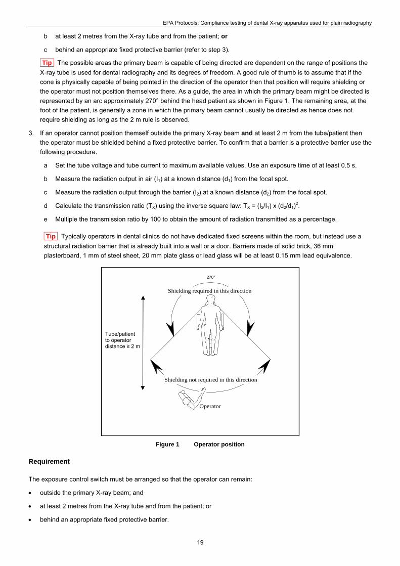
Tip The possible areas the primary beam is capable of being directed are dependent on the range of positions the
X-ray tube is used for dental radiography and its degrees of freedom. A good rule of thumb is to assume that if the
cone is physically capable of being pointed in the direction of the operator then that position will require shielding or
the operator must not position themselves there. As a guide, the area in which the primary beam might be directed is
represented by an arc approximately 270° behind the head patient as shown in Figure 1. The remaining area, at the
foot of the patient, is generally a zone in which the primary beam cannot usually be directed as hence does not
require shielding as long as the 2 m rule is observed.
3. If an operator cannot position themself outside the primary X-ray beam and at least 2 m from the tube/patient then
the operator must be shielded behind a fixed protective barrier. To confirm that a barrier is a protective barrier use the
following procedure.
a Set the tube voltage and tube current to maximum available values. Use an exposure time of at least 0.5 s.
b Measure the radiation output in air (I1) at a known distance (d1) from the focal spot.
c Measure the radiation output through the barrier (I2) at a known distance (d2) from the focal spot.
d Calculate the transmission ratio (TX) using the inverse square law: TX = (I2/I1) x (d2/d1)2.
e Multiple the transmission ratio by 100 to obtain the amount of radiation transmitted as a percentage.
Tip Typically operators in dental clinics do not have dedicated fixed screens within the room, but instead use a
structural radiation barrier that is already built into a wall or a door. Barriers made of solid brick, 36 mm
plasterboard, 1 mm of steel sheet, 20 mm plate glass or lead glass will be at least 0.15 mm lead equivalence.
270°
Shielding required in this direction
Shielding not required in this direction
Tube/patient to operator distance ≥ 2 m
Operator
Figure 1 Operator position
Requirement
The exposure control switch must be arranged so that the operator can remain:
outside the primary X-ray beam; and
at least 2 metres from the X-ray tube and from the patient; or
behind an appropriate fixed protective barrier.
19

EPA Protocols: Compliance testing of dental X-ray apparatus used for plain radiography
Tip
A protective barrier is one that has a lead equivalence of 0.15 mm. If the transmitted radiation is no more than 10%
of the incident radiation the barrier is deemed to comply with this test.
A fixed barrier is a one that cannot be readily removed. The EPA accepts that, while a shielded door loses its
shielding capacity by simply opening the door, the door is fixed as it cannot be readily removed.
There is no regulatory requirement governing the height or width of a protective barrier. But the barrier must be of
sufficient dimensions so that the operator cannot be exposed to the primary beam.
While the EPA recommends to owners and operators that the operator should be able to view the patient during a
radiation exposure, this is not a regulatory requirement and not mandatory under this protocol.
For an apparatus used in a hand held manner, the owner may have been granted an exemption from Regulation
91(10). Please contact the EPA for advice.
Compliance reference
Regulation 91(10).
2.32 Shielding*
Important Note When evaluating a room that may have been previously assessed (ie by a accredited tester or an
Officer of the EPA), do not assume that the shielding is still adequate as the room’s configuration and shielding may have
changed since its last inspection.
Purpose
To ensure members of the public (ie any person not operating the apparatus) are appropriately shielded from the
radiation from an energised X-ray apparatus.
Method
1. Floor plan: make a sketch of the layout of the area in which the apparatus is installed. The sketch should include
detail of:
a the X-ray apparatus
b the patient chair
c windows (where applicable)
d doors (including all entrances used to directly access the area)
e the normal position of the operator
f adjacent areas (eg hallway, reception area, offices, staff room, store room, dark room, adjacent business,
adjacent surgeries, external car parks, external walk ways)
g the approximate dimensions of important features (eg size of room and distances from the apparatus to the
operator position). Note that the sketch need not be to a precise scale.
2. Normally occupied: identify areas where the primary beam of the apparatus is likely to be directed that are:
a normally occupied by a person: and
b are less than 5 metres from the X-ray tube.
For each area that is normally occupied annotate on your sketch accordingly.
Tip an area is normally occupied when a person is located in the area for a period other than a short period of
time. Examples of normally occupied areas are a reception area, a patient waiting area, a patient recovery area, a
20

EPA Protocols: Compliance testing of dental X-ray apparatus used for plain radiography
Practice Manager’s office, busy staff rooms, an adjacent surgery, an adjacent business of any kind. Conversely
areas such as hallways, infrequently used offices, infrequently used staff rooms, store rooms, dark rooms, external
car parks, and external walk ways are not generally considered normally occupied.
3. Radiation barriers: for each area that has been identified as being normally occupied confirm that between the area
of concern and the X-ray tube there is a fixed protective barrier. Often the only way to confirm this is by a performing
a transmission measurement. Use the following procedure.
a Set the tube voltage and tube current to maximum available values. Use an exposure time of at least 0.5 s.
b Measure the radiation output through air (I1) at a known distance (d1) from the focal spot.
c Measure the radiation output through the barrier (I2) at a known distance (d2) from the focal spot.
d Calculate the transmission ratio (TX) using the inverse square law. That is: TX = (I2/I1) x (d2/d1)2.
e Multiple the transmission ratio by 100 to obtain the amount of radiation transmitted as a percentage.
f Annotate on the sketch the points (ie wall, door, etc) at which shielding measurements are performed.
Tip Barriers made of solid brick, 36 mm plasterboard, 1 mm of steel sheet, 20 mm plate glass or lead glass will be
at least 0.15 mm lead equivalence.
Requirement
If the primary beam of the apparatus is likely to be directed at an area normally occupied by a person that is less than 5
metres from the X-ray tube, a fixed protective barrier must be provided.
Tip
A protective barrier is one that has a lead equivalence of 0.15 mm. If the transmitted radiation is no more than 10%
of the incident radiation the barrier is deemed to comply with this test.
A fixed barrier is a one that cannot be readily removed. The EPA accepts that, while a shielded door loses its
shielding capacity by simply opening the door, the door is fixed as it cannot be readily removed.
There is no regulatory requirement governing the height or width of a protective barrier. But the barrier must be of
sufficient dimensions so that a person cannot be exposed to the primary beam within 5 m of the X-ray tube.
Compliance reference
Regulations 91(11) and 91(12).
21
EPA Protocols: Compliance testing of dental X-ray apparatus used for plain radiography
3 References
Compliance Statement (Form 91A)— Dental X-ray apparatus used for plain radiography, Environment Protection
Authority.
EPA Guidelines—Program requirements for compliance testing of diagnostic X-ray apparatus, Environment
Protection Authority.
EPA Guideline—Personal radiation monitoring devices, Environment Protection Authority, 2009.
Safety Signs for the Occupational Environment, Australian Standard 1319−1994.
<www.saiglobal.com/shop/script/search.asp>.
22

EPA Protocols: Compliance testing of dental X-ray apparatus used for plain radiography
Annex 1 Radiation signs
Figure 2 Radiation Produced When Energised
Figure 3 Radiation symbol
Figure 4 Radiation symbol plus radiation warning
23
Top Related