


Languages
Pages
Legal


816,3672 AND 36112
KEY TELEPHONE SYSTEM
FORM 2993101 EDecrmber 1989
TECHNICALMANUAL

INDEX
This manual supports the following ENCORE CX systems: 816.3672, and 36112. The table below shows how themanual is organized. To locate specific information, proceed as follows: first, look under the description columnof the table for the system (816, 3672, 36112) and type of information you’re looking for programming); then proceed to the tab indicated in the third column of the table. Locate the sectionnumber (first column) within the table. Each section has own table of contents.
Section Description Tab
100 ENCORE CX 816 System Description and Features 1101 ENCORE CX 3672 System Description and Features 1102 ENCORE CX 36112 System Description and Features 1
200 ENCORE CX 816 Operating Instructions201 ENCORE CX 3672 Operating Instructions
202 ENCORE CX 36112 Operating Instructions300 ENCORE CX 816 Technical Specifiitions 3
301 ENCORE CX 3672 Technical Specifications302 ENCORE CX 36112 Technical 400 ENCORE CX Design And Configuration 4401 ENCORE CX 3672 Least Cost Routing (LCR) 4
ENCORE CX 36112 Design And Configuration
500 I
600
General Regulatory Agency Information
ENCORE CX 816 Installation instructions601 ENCORE CX 3672 Installation Instructions 8602 ENCORE CX 36112 Installation 6
700 ENCORE CX 816 Programming Procedures701 ENCORE CX 3672 Programming Procedures 3ENCORE CX 3672 Cost Routing (LCR)
36112 Programming Procedures ,
7
702 ENCORE CXENCORE CX 816 Checkout Procedures 3ENCORE CX 3672 Checkout ProceduresENCORE Information 8
901 ENCORE CX 3672 Service 1000 Technical Facts Record of Changes 1X
-iii-

E N C O R E " C X 3 6 7 2 K E Y T E L E P H O N E S Y S T E M N o . 1 6 0 8O c t o b e r 2 , 1 9 8 7
F o r D i s t r i b u t o r s O n l y
E N C O R E ' C X 3 6 7 2 S O F T W A R E R E L E A S E
A n e w v e r s i o n s o f t w a r e , i s n o w a v a i l a b l e f o r t h e C e n t r a l P r o c e s s o r B o a r d ( 2 9 9 4 4 0 1 )u s e d i n t h e E N C O R E C X 3 6 7 2 k e y t e l e p h o n e s y s t e m . C e n t r a l P r o c e s s o r B o a r d s s h i p p e d o n o ra f t e r O c t o b e r 1, 1987, w i l l h a v e t h e n e w s o f t w a r e . T h e E N C O R E C X 3 6 7 2 P R O M p r o g r a mo n p a g e 2 o f t h i s T e c h n i c a l F a c t s m a k e s a v a i l a b l e a P R O M e x c h a n g e p r o g r a m f o r f i e l du p g r a d e s . u p g r a d e w i l l n o t r e q u i r e t h e o f t h e c u s t o m e r d a t a b a s e .
T h e e n h a n c e d v e r s i o n o f s o f t w a r e i n c l u d e s i m p r o v e m e n t s i n f e a t u r e o p e r a t i o n s a n dc o r r e c t s i d e n t i f i e d p r o b l e m s . D e t a i l s o f c h a n g e sa v a i l a b l e i n a n u p c o m i n g T e c h n i c a l F a c t s .
i n f e a t u r e o p e r a t i o n s w i l l b e
C o r r e c t i o n O f P r o b l e m s
L i s t e d b e l o w a r e t h e m o s t c o m m o n l y r e p o r t e d p r o b l e m s c o r r e c t e d i n v e r s i o n t h a t m a yb e e n c o u n t e r e d :
1. U N A C a l l S k i p
W h e n u s i n g t h e U N A f e a t u r e ,. d i a l i n g s y s t e m c o d e 7 7 .
o n l y e v e r y o t h e r i n c o m i n g C a l l c o u l d b e a n s w e r e d b y
2 . C . O . L i n e L o c k u p
W h e n u s i n g t h e l o o p s u p e r v i s i o n f e a t u r e , a s t a t i o n u s e r c o u l d b e d i s c o n n e c t e d f r o m as e c o n d o u t s i d e c a l l i f h i s f i r s t o u t s i d e c a l l e r , w h i c h h e p u t o n s y s t e m h o l d , h a n g s
T h e s e c o n d o u t s i d e c a l l w o u l d a p p e a r i n - u s e o n a l l s t a t i o n s a n d c o u l d n o t b er e - e n t e r e d .
3 . C a n c e l l a t i o n O f L a s t N u m b e r R e d i a l
T h e L a s t N u m b e r R e d i a l f e a t u r e m a y h a v e s t o r e d d i g i t s c a n c e l l e d b y m a n y s t a t i o no p e r a t i o n s n o t r e l a t e d t o a n e w o u t s i d e c a l l a t t e m p t , i . e . a n s w e r i n g a n i n c o m i n gc a l l .
4 . R e s e t L o c k u p o f K I B o r C O B P o r t s
S o m e K I B o r c a r d s m a y a c t a s i f t h e y a r e i n t h e O f S e r v i c e " m o d e a f t e r aC P B r e s e t e v e n t .
F i l e a c o p y o f t h i s T e c h n i c a l F a c t s i n y o u r A l a n P e n i c kM a s t e r T e c h n i c a l F a c t s F i l e a n d i n y o u rE N C O R E C X 8 1 6 a n d 3 6 7 2 T e c h n i c a l M a n u a l ,
P r o d u c t L i n e M a n a g e r
F o r m a n d 29931018. l i s t i t o nt h e R e c o r d O f C h a n g e s p a g e .
A t t a c h m e n t s : P R O M R e t u r n A u t h o r i z a t i o n F o r m
P a g e 1 o f 3

E N C O R E C X 3 6 7 2 P R O M P r o g r a m
T h e E N C O R E C X 3 6 7 2 P R O M p r o g r a m o f f e r s a m e t h o d t o o b t a i nt o u p g r a d e y o u r p r e s e n t c u s t o m e r s a n d i n - h o u s e i n v e n t o r y .
O r d e r p a r t A 6 9 2 0 2 f r o m D i s t r i b u t o r S e r v i c e s f o r t h e
v e r s i o n s o f t w a r e f o r y o u
s o f t w a r e b y P R O M s e t s f o r .r e p l a c e m e n t i n t h e f i e l d . P a r t A 6 9 2 0 2 r e p r e s e n t s a c o m p l e t e s e t o f s i x ( 6 ) n e c e s s a r y t o c h a n g e s o f t w a r e i n o n e (1) s y s t e m . Q u a n t i t i e s f o r t h e P R O M s e t s w i l l b ec o n t r o l l e d b y a l l o c a t i o n . $115.00 w i l l b e c h a r g e d f o r e a c h P R O M s e t . B y r e t u r n i n g t h eo l d P R O M s e t s , u s i n g t h e i n s t r u c t i o n o n t h e a t t a c h e d P R O M r e t u r n f o r m , f u l l c r e d i t f o re a c h P R O M s e t p a s s i n q r e t u r n i n s p e c t i o n w i l l b e i s s u e d . A n e w o r d e r f o r a n a d d i t i o n a l
o f P R O M s e t s b e a l l o w e d a f t e r t h e r e c e i p t a n d a c c e p t a n c e o f t h e o l d P R O Ms e t s i n S a n D i e g o .
T h e a l l o c a t i o n o f P R O M s e t s e n s u r e s t h a t e a c h d i s t r i b u t o r w i l l r e c e i v e a f a i r s h a r e a n dr e d u c e t h e c h a n c e f o r b a c k - o r d e r p r o b l e m s . It i s v e r y t h a t s e t s o r d e r e da r e i n s t a l l e d q u i c k l y a n d o l d P R O M s e t s a r e r e t u r n e d
N o c r e d i t w i l l b e i s s u e d f o r a n y o l d P R O M s e t s r e c e i v e d a f t e r t h e c l o s e o f b u s i n e s sD e c e m b e r 3 1 , 1 9 8 7 .
A l l E N C O R E C X C e n t r a l P r o c e s s o r B o a r d s ( 2 9 9 4 4 0 1 ) s h i p p e d o r r e p a i r e d o n o r a f t e r O c t o b e r' 9 8 7 , f r o m o u r S a n D i e g o w a r e h o u s e a n d r e p a i r c e n t e r w i l l h a v e t h e n e w s o f t w a r e
i n c l u d e d . A f t e r D e c e m b e r 3 1 , 1987, a l l C e n t r a l P r o c e s s o r B o a r d s (2994401) s e n tt o t h e r e p a i r c e n t e r w i l l b e u p g r a d e d u p o n r e q u e s t o n l y .
N o r m a l r e p a i r c h a r g e s w i l l a p p l y f o r a n y c a r d s s e n t i n a f t e r t h e w a r r a n t y p e r i o de x p i r e s .
H o w T o O b t a i n V e r s i o n S e t s
P l e a s e u s e t h e f o l l o w i n g p r o c e d u r e t o o b t a i n n e w P R O M s e t s .
1. C a l l D i s t r i b u t o r S e r v i c e s w i t h a p u r c h a s e o r d e r f o r p a r t A 6 9 2 0 2 . T h e y w i l l i n f o r my o u o f t h e q u a n t i t y t h a t y o u h a v e b e e n a l l o c a t e d . $115.00 p e r P R O M s e t w i l l b ec h a r g e d .
2 . U p o n r e c e i v i n g t h e n e w P R O M s e t s , e x c h a n g e a s q u i c k l y a s p o s s i b l e i n d e s i r e d C P B(2994401) cards.
P a g e 2 o f 3 T F 1 6 0 8
3.
4.
5.
R e t u r n o l d P R O M s e t s i m m e d i a t e l y u s i n g t h e i n s t r u c t i o n s o n t h e R e t u r n a t t a c h e d t o t h i s T e c h n i c a l F a c t s . S e n d t h e f o r m a l o n g w i t h t h e P R O M s e t s .
A c r e d i t o f $115.00 w i l l b e i s s u e d f o r e a c h P R O M s e t r e t u r n e d a n d p a s s i n gi n s p e c t i o n . A d d i t i o n a l a l l o c a t i o n q u a n t i t i e s w i l l t h e n b e a l l o w e d .
F o l l o w t h i s p r o c e d u r e a g a i n i f a d d i t i o n a l P R O M r e q u i r e d .
I n s t a l l i n g N e w S e t s
T h e
1.
f o l l o w i n g s t e p s s h o u l d b e f o l l o w e d w h e n e x c h a n g i n g P R O M S o n t h e C P B (2994401).
E n s u r e s w i t c h 8 o n t h e DIP s w i t c h o f t h e C P B i s i n t h e O F F p o s i t i o n . T h i s w i l lp r o t e c t t h e c u s t o m e r ' s d a t a b a s e .
2.
3.
4.
T u r n O F F t h e p o w e r s w i t c h o n t h e D C / D C c o n v e r t e r .
5.
6.
U s i n g r e m o v a l t a b s , r e m o v e t h e C P B c a r d .
P l a c e C P B c a r d , c o m p o n e n t s i d e u p , o n a w e l l - l i g h t e d , c l e a n n o n - c o n d u c t i v es u r f a c e . U s e a l l n o r m a l p r o c e d u r e s f o r h a n d l i n g s t a t i c - s e n s i t i v e c a r d s .
L o c a t e s i x m o u n t e d i n c h i p s o c k e t s m a r k e d G 2 , 3 , 4 , 5 , 8 a n d 9 . C a r e f u l l yr e m o v e , u s i n g p r o p e r t o o l s , o l d a n d s e t a s i d e f o r p r o p e r p a c k i n g .
R e m o v e t h e n e w P R O M s e t f r o m i t s p a c k i n g t u b e a n d i n s e r t e a c h P R O M c a r e f u l l y i n t h ep r o p e r c h i p s o c k e t . A l l s i x P R O M S a r e m a r k e d w i t h a n u m b e r f o r m a t c h i n g t o ac h i p s o c k e t . M a k e c e r t a i n e a c h P R O M i s i n s e r t e d i n t h e p r o p e r d i r e c t i o n ( p i n o n e t op i n o n e ) .
7. C a r e f u l l y i n s p e c t e a c h P R O M t o e n s u r e i t i s i n s t a l l e d p r o p e r l y w i t h o u t a n y d a m a g e t op i n s .
8. I n s e r t t h e C P B i n t o t h e s y s t e m a n d t u r n t h e D C / D C c o n v e r t e r o n .
9. P r e s s t h e r e s e t b u t t o n o n t h e C P B a n d t h e n c h e c k f o r n o r m a l s y s t e m o p e r a t i o n .
10. P a c k o l d t h e p a c k i n g t u b e a n d s e c u r e .
N O T E : I t s h o u l d n o t b e n e c e s s a r y t o r e - p r o g r a m a n y c u s t o m e r d a t a i f a l l p r o c e d u r e s a r ef o l l o w e d c a r e f u l l y .
P L E A S E P A C K A G E S E T S P R O P E R L Y F O R R E T U R N
D e v i c e s r e c e i v e d w i l l b e s c r e e n e d f o r p h y s i c a l d a m a g e ( b e n t , b r o k e n p i n s , b r o k e n c a s e s ,e t c . ) a n d t o e n s u r e t h a t c o m p l e t e s e t s a r e i n c l u d e d p r i o r t o c r e d i t a p p r o v a l a n d r e -a l l o c a t i o n f o r r e - o r d e r s .
T F 1 6 0 8 P a g e 3 o f 3

.-. .
E N C O R E " ' C X 3 6 7 2 K E Y T E L E P H O N E S Y S T E M N o . 1616O c t o b e r 2 3 , 1 9 8 7
F o r D i s t r i b u t o r s O n l y
E N C O R E C X 3 6 7 2 S O F T W A R E R E L E A S E
W e h a v e m a d e a c h a n g e f r o m t h e s o f t w a r e v e r s i o n o u t l i n e d i n T e c h n i c a l F a c t s N o . 1 6 0 8d a t e d O c t o b e r 2 , 1987.c h i p s e t s i s
T h e n e w s o f t w a r e v e r s i o n f o r a n d P R O M e x c h a n g e p r o g r a m
T h e p u r p o s e o f t h i s T e c h n i c a l F a c t s i s t o o u t l i n e s o m e c h a n g e s i n f e a t u r e o p e r a t i o n a n da c t i v a t i o n w h i c h h a v e b e e n m a d e t o t h e E N C O R E C X 3 6 7 2 s y s t e m . M a n y o f t h e s e c h a n g e sa n d i m p r o v e m e n t s h a v e b e e n m a d e b a s e d o n r e q u e s t s f r o m c u s t o m e r s a n d o u r s a l e s f o r c e .O t h e r s w e r e m a d e t o c o r r e c t o m i s s i o n s o r m i s u n d e r s t a n d i n g s i n i n t e r p r e t a t i o n o f t h es p e c i f i c a t i o n f o r t h e E N C O R E C X .
T h e s e c h a n g e s a r e a c c o m p l i s h e d i n S o f t w a r e V e r s i o n o n t h e E C X 3 6 7 2 s y s t e m w h i c hb e g a n s h i p p i n g o n a l l f o r t h e E C X 3 6 7 2 s h i p p e d a s o f I n a d d i t i o n ,b e c a u s e o f t h e i m p o r t a n c e o f s o m e o f t h e s e f e a t u r e s t o y o u r c u s t o m e r s , w e h a v e m a d e i tp o s s i b l e t o c h a n g e o u t t h e o n a l r e a d y - i n s t a l l e d s y s t e m s w i t h o u t h a v i n g t or e p r o g r a m t h e c u s t o m e r ' s D a t a B a s e . T h e s e n e w s e t s o f s i x ( 6 ) P R O M c h i p s c a n b eo r d e r e d b y y o u r o p e r a t i o n s p e o p l e u s i n g p a r t A 6 9 2 0 2 , a n d i f t h e o l d s e t o f P R O M c h i p s .i s r e t u r n e d , t h e r e w i l l b e n o c h a r g e f o r t h e n e w v e r s i o n . S e e T e c h n i c a l F a c t s N o .1 6 0 8 f o r d e t a i l s o n t h e E N C O R E C X 3 6 7 2 P R O M E x c h a n g e p r o g r a m .
B e l o w i s a l i s t o f t h e m o s t s i g n i f i c a n t c h a n g e s w h i c h h a v e b e e n i m p l e m e n t e d b e t w e e nS o f t w a r e V e r s i o n ( t h e o n l y v e r s i o n w h i c h h a s s h i p p e d s i n c e t h e l a u n c h o f t h e E C X )a n d t h e n e w S o f t w a r e V e r s i o n
A t t e n d a n t R e c a l l
R e c a l l s t o a n a t t e n d a n t w i l l t o a l l a t t e n d a n t s s i m u l t a n e o u s l y .
C a l l b a c k R e q u e s t s
I f a s t a t i o n h a s s e v e r a l C a l l b a c k R e q u e s t s o n t h e i r s e t , t h e y c a n r e t u r n t h e m i n a n yo r d e r b y d i a l i n g t h e s e l e c t e d s t a t i o n n u m b e r . T h a t p r o c e d u r e w i l l c a n c e l t h e C a l l b a c kR e q u e s t f o r t h e s t a t i o n d i a l e d .
F i l e a c o p y o f t h i s T e c h n i c a l F a c t s i ny o u r M a s t e r F a c t s F i l e a n d i ny o u r E N C O R E C X 8 1 6 a n d 3 6 7 2 T e c h n i c a lM a n u a l , F o r m 2993101A a n d 29931018. A l s o
, l i s t i t o n t h e R e c o r d O f C h a n g e s p a g e . ,
A l a n P e n i c kP r o d u c t L i n e M a n a g e r
P a g e 1 o f 4
F o r w a r d
a s t a t i o n m a n u a l l y f o r w a r d s i t s c a l l s , t h e n n e w l y r i n g i n g i n c o m i n g ( a s w e l l a s C . O . l i n e s w i l l f o l l o w t h e f o r w a r d .
F o r w a r d f o r A t t e n d a n t
l o w t h e a t t e n d a n t c a n m a n u a l l y f o r w a r d h i s / h e r t e l e p h o n e a n d t h e r i n g i n g o f i n c o m i n g l i n e c a l l s w i l l f o l l o w t h e f o r w a r d . H o w e v e r , r e c a l l s b a c k t o t h e a t t e n d a n t d o n o t
P a r k R e c a l l
c a l l r e c a l l i n g f r o m a p a r k i n g o r b i t w i l l n o w r i n g t h e s t a t i o n p a r k i n g t h e c a l l f o r S y s t e m H o l d t i m e b e f o r e r e c a l l i n g t o t h e a t t e n d a n t .
T i m e r
a n a d d i t i o n a l s e c u r i t y f e a t u r e w e h a v e c h a n g e d t h e s y s t e m s o t h a t t h e C o n f e r e n c e s e t i n s y s t e m m e m o r y w i l l a p p l y t o U n s u p e r v i s e d C o n f e r e n c e a n d D I S A c a l l s . It i s
r e c o m m e n d e d t h a t b o t h o p t i o n s b e u s e d o n a l l s y s t e m s w h e r e t h e C . O . p r o v i d e s a n d w h e n t h e C . O . d o e s . n o t , C o n f e r e n c e T i m e r b e u s e d to
a l o n g d i s t a n c e b i l l f o r c a l l ( s ) l a s t i n g m a n y h o u r s .
C a l l P i c k - U p
' h i s f e a t u r e h a s n o w b e e n c h a n g e d s o t h a t i t c a n b e u s e d t o a n s w e r a n e w l y r i n g i n g C . O . L i n e a n d a H a n d s f r e e Intercom c a l l a s w e l l a s a t o n e r i n g i n g i n t e r c o m
N o t D i s t u r b W a r n i n g T o n e S e t )
' h e l e n g t h o f t h e w a r n i n g t o n e s e n t t o a S i n g l e L i n e T e l e p h o n e i n D N D h a s b e e ne n g t h e n e d f r o m 3 t o 6 b u r s t s o f t o n e . ( O v e r two (2) s e c o n d s o f w a r n i n g t o n e . )
P a i r s
D N D O v e r r i d e o f a n E x e c u t i v e / S e c r e t a r y p a i r o r a S t a t i o n C a l l b a c k t o a n E x e c u t i v e / p a i r w i l l a p p l y t o t h e s e t p r o g r a m m e d a s t h e s e c r e t a r y o f t h e p a i r .
P a g e 2 o f 4

F l e x i b l e B u t t o n A d d i t i o n s
C a l l P a r k P i c k - U p a n d S t a t i o n H u n t G r o u p d i a l i n g c a n n o w b e a s f l e x i b l es t a t i o n b u t t o n s b y t h e u s e r . U s e t h e e s t a b l i s h e d p r o c e d u r e a n d c o d e s f o r p r o g r a m m i n g .
L a s t N u m b e r R e d i a l
If a s t a t i o n a n s w e r s a n I n c o m i n g C . O . l i n e r i n g i n g o n t h e i r t e l e p h o n e o r a c c e s s e s al i n e w h i c h h a s b e e n p u t o n H o l d b y t h e n u m b e r s t o r e d i n L a s t N u m b e rR e d i a l m e m o r y w i l l n o t n o w b e e r a s e d . T h e s a m e C . O . l i n e w i l l b e u s e d w h e n L a s t N u m b e rR e d i a l i s a c t i v a t e d .
S e c o n d L e v e l o f R e c a l l
A c a l l p l a c e d o n S y s t e m H o l d , E x c l u s i v e H o l d o r i n a C a l l P a r k o r b i t w i l l r i n g t h es t a t i o n i n v o k i n g t h e f e a t u r e a n d t h e n b o t h t h a t s t a t i o n a n d a l l a t t e n d a n t s .
S t a t i o n M e s s a g e D e t a i l R e c o r d i n g
C o l u m n H e a d e r s h a v e b e e n a d d e d w h i c h w i l l p r i n t e v e r y 6 6 l i n e s f o r S M D R a p p l i c a t i o n sw h i c h o u t p u t d i r e c t l y t o a p r i n t e r .
S M D R n o w p r o v i d e s a n i n d i c a t i o n o f t h e t y p e o f c a l l r e c o r d e d a s t h e f i r s t e n t r y i n t h e" D i a l e d D i g i t s " f i e l d :
I I n c o m i n g C a l l
O u t g o i n g C a l lT r a n s f e r r e d C a l l
S y s t e m S p e e d D i a l R e s t r i c t i o n
If a s t a t i o n i s r e s t r i c t e d f r o m a c c e s s t o D i a l a n d a c c e s s e s a C . O . l i n ea n d t h e n a t t e m p t s t o d i a l a s y s t e m s p e e d d i a l b i n , e r r o r t o n e w i l l b e h e a r d a n d t h el i n e w i l l b e d i s c o n n e c t e d .
T r a n s f e r R e c a l l
T h e f i r s t T r a n s f e r R e c a l l r i n g s b o t h t h e t r a n s f e r r i n g a n d t h e t r a n s f e r r e d t o s t a t i o n ,a n d t h e s e c o n d T r a n s f e r R e c a l l r i n g s b o t h s t a t i o n s a n d a l l a t t e n d a n t s .
P a g e 3 o f 4 TF1616

U n s u p e r v i s e d C o n f e r e n c e
F o r a s t a t i o n t o e s t a b l i s h a n U n s u p e r v i s e d C o n f e r e n c e i t i s n o w n e c e s s a r y f o r t h a ts t a t i o n t o p r e s s t h e k e y a n d t h e n h a n g u p .o u t s i d e l i n e s w i l l b e d i s c o n n e c t e d .
I f t h e s t a t i o n j u s t h a n g s u p , t h eT h i s i s a m a j o r c h a n g e f r o m p r e v i o u s o p e r a t i o n .
U n i v e r s a l N i g h t
P r e v i o u s l y s o m e c a l l s r i n g i n g i n a t n i g h t o v e r U N A c o u l d n o t b e a n s w e r e d b y d i a l i n gs y s t e m c o d e 7 7 . T h i s h a s b e e n c o r r e c t e d s o t h a t a n y c a l l r i n g i n g i n a t n i g h t c a n b ea n s w e r e d b y d i a l i n g t h e U N A a n s w e r c o d e o f 7 7 .
W e h a v e a d d e d a p r o v i s i o n s o t h a t U N A r i n g i n g c a n b e a u t o m a t i c a l l y a s s i g n e d t o L o u d C o n t r o l 1 e v e n i f n o i n s t r u m e n t i n t h e s y s t e m i s p r o g r a m e d t o r i n g f o r a l l
l i n e s . ( U s e F l a s h 1 3 c o m m a n d . )
W e w i l l c o n t i n u e o u r e f f o r t s t o i m p r o v e t h i s p r o d u c t t h r o u g h o u t i t s l i f e c y c l e t o k e e pi t a s v i a b l e a n d s a l e a b l e i n t h e m a r k e t a s w e p o s s i b l y c a n . T o w a r d t h a t e n d w e a r ev e r y i n d e b t e d t o y o u f o r i n b r i n g i n g p r o b l e m s a s w e l l a s p o s s i b l e t o o u r a t t e n t i o n , a n d w e w i s h t o t a k e t h i s o p p o r t u n i t y t o t h a n k y o u f o r
. . v a l u a b l e c o n t r i b u t i o n s t o t h i s e f f o r t o f c o n t i n u i n g i m p r o v e m e n t a n d e n h a n c e m e n t . '
T F 1 6 1 6 P a g e 4 o f 4

E N C O R E ' " C X 3 6 7 2 K E Y T E L E P H O N E S Y S T E M N o . 1 6 1 9D e c e m b e r 2 3 , 1 9 8 7
F o r D i s t r i b u t o r s O n l y
E N C O R E C X 3 6 7 2 R E L E A S E 2 . 0 6
A s p a r t o f o u r o n g o i n g e f f o r t t o i m p r o v e t h e o p e r a t i o n o f t h e E N C O R E C X 3 6 7 2 s y s t e m , h a v e a p p r o v e d t h e r e l e a s e o f v e r s i o n 2 . 0 6 s o f t w a r e . T h i s r e p l a c e s t h e v e r s i o n 2 . 0 1p r e v i o u s l y u s e d .
A l l o r d e r s f o r C P B c a r d 2994401 s h i p p e d a s o f a n d o r d e r s f o r p a r t N o . A 6 9 2 0 .( u p g r a d e d s o f t w a r e f o r t h e C P B c a r d ) s h i p p e d a s o f c o n t a i n t h e v e r s i o n . 2 . 0 6 .
T h e c h a n g e s m a d e i n v e r s i o n 2 . 0 6 c o r r e c t i d e n t i f i e d p r o b l e m s f o u n d i n v e r s i o n a f f e c t t h e a l l o c a t i o n o f s y s t e m r e s o u r c e s a s w e l l a s a n S L T f e a t u r e o p e r a t i o n s e t s ) .
1 . W h e n u s i n g ( 2 5 0 0 s e t s ) i n t h e s y s t e m :
A c h a n g e m a d e i n t h e a l l o c a t i o n o f D T M F r e c e i v e r s o n t h e A P L a n d / o r R S M r e d u c e s t h e c h a n c e s f o r r e c e i v e r c o n g e s t i o n . C o n g e s t i o n o f t h e D T M F r e c e i v e r !c a u s e s S L T u s e r s t o h a v e d e l a y e d o r n o s y s t e m d i a l t o n e w h e n g o i n g o f f h o o k .
P r e v i o u s l y , i f S L T s t a t i o n A u s e d d i r e c t e d o r g r o u p c a l l p i c k u p t o a n s w e r a c a lr i n g i n g a t S L T s t a t i o n B , s t a t i o n A c o u l d n o t t r a n s f e r t h e p i c k e d - u p c a l l a n o t h e r s t a t i o n . T h e n e w s o f t w a r e a l l o w s a n S L T s t a t i o n t o t r a n s f e r t h e p i c k e d - qc a l l .
2 . S M D R f r o m t h e R S - 2 3 2 p o r t :
C o r r e c t i o n s h a v e b e e n m a d e f o r a n S M D R d a t a f l o w i n t e r r u p t i o n p r o b l e m . T h i s d u e t o a n u n w a n t e d s i g n a l s e n t b a c k t o t h e K S U w h e n p o w e r t o s o m e p r i n t e r s t e r m i n a l s i s s w i t c h e d o f f a n d o n . T h i s c o n d i t i o n b l o c k s a l l a c t i v i t y o n t h e R S - 2 3 ;p o r t o n t h e C P B c a r d u n t i l t h e s y s t e m i s r e s e t .
A l a n P e n i c kP r o d u c t L i n e M a n a g e r
F i l e a c o p y o f t h i s T e c h n i c a l F a c t s i ny o u r M a s t e r T e c h n i c a l F a c t s F i l e a n d i ny o u r E N C O R E C X 8 1 6 a n d 3 6 7 2 M a n u a l , F o r m 2993101A a n d 29931018. A l s ol i s t i t o n t h e R e c o r d O f C h a n g e s p a g e .
( o v e r )

3 . M u l t i - p a r t y c o n f e r e n c e :
C o r r e c t i o n s h a v e b e e n m a d e i n 2 . 0 6 s o f t w a r e t o e l i m i n a t e u n w a n t e d c o n f e r e n c e s . I ne a r l i e r s o f t w a r e v e r s i o n s , a n u n w a n t e d c o n f e r e n c e c o u l d o c c u r a s a r e s u l t o f t h eo r i g i n a t o r o f a m u l t i - p a r t y c o n f e r e n c e e x i t i n g t h e c o n f e r e n c e i n p r o g r e s s . I n t h i ss i t u a t i o n , a s u b s e q u e n t c a l l i n t h e s y s t e m c o u l d b e i n a d v e r t e n t l y a d d e d t o t h ec o n f e r e n c e i n p r o g r e s s . T h i s s y m p t o m u s u a l l y o c c u r s i n c o n f e r e n c e s i n v o l v i n g f o u ri n t e r n a l p a r t i e s a n d o n e e x t e r n a l p a r t y .
SOFTWARE FIELD REPLACEUENTS
I f y o u r c u s t o m e r s h a v e e x p e r i e n c e d a n y o f t h e a b o v e c o n d i t i o n s i n s y s t e m s u s i n g p r e v i o u ss o f t w a r e v e r s i o n s , w e r e c o m m e n d t h a t y o u o b t a i n v e r s i o n 2 . 0 6 b y u s i n g t h e P R O M e x c h a n g ep r o g r a m d e t a i l e d i n T e c h n i c a l F a c t s 1 6 0 8 .
T h i s T e c h n i c a l F a c t s o f f i c i a l l y e x t e n d s t h e P R O M e x c h a n g e p r o g r a m i n t r o d u c e d i n T e c h' a c t s 1 6 0 8 u n t i l A p r i l 1 , 1 9 8 8 , f o r t h o s e d i s t r i b u t o r s w h o w i s h t o e q u i p i n s t a l l e d 3 6 7 2s y s t e m s w i t h t h e l a t e s t s o f t w a r e v e r s i o n ( 2 . 0 6 ) .
P a g e 2 o f 2

E N C O R E ' " C X K E Y T E L E P H O N E S Y S T E M N o . 1621J a n u a r y 2 9 , 1 9 8 8
F o r A l l O i s t r i b u t o r s
SIB
W e h a v e i d e n t i f i e d c e r t a i n p r o b l e m s t h a t m a y b e e n c o u n t e r e d w h e n i n s e r t i n g S I B c a r d s .E r r a t i c s y s t e m o p e r a t i o n a n d c r o s s t a l k m a y r e s u l t f r o m i n s e r t i n g a n d / o r r e m o v i n g t h e c a r d s w h e n t h e u n d e r p o w e r . A h i g h f a i l u r e r a t e o f S I B c a r d s m a y a l s o b ee x p e r i e n c e d . A l l SIB c a r d s ( 2 9 9 3 7 0 4 ) b e a r i n g s e r i a l n u m b e r 7 1 0 9 9 9 9 9 o r l o w e r , s h i p p e db e f o r e D e c e m b e r 7 , 1987, f r o m t h e S a n D i e g o w a r e h o u s e , c o u l d e x h i b i t t h e s e s y m p t o m s .
A l l S I B c a r d s ( 2 9 9 3 7 0 4 ) b e a r i n g s e r i a l n u m b e r 7 1 1 0 0 0 0 0 o r h i g h e r , s h i p p e d a f t e r D e c e m b e r7 , 1 9 8 7 , f r o m t h e S a n D i e g o w a r e h o u s e , h a v e b e e n m o d i f i e d t o e l i m i n a t e t h e p r o b l e m sa s s o c i a t e d w i t h i n s e r t i o n a n d r e m o v a l u n d e r p o w e r .
S I B c a r d s r e q u i r i n g m o d i f i c a t i o n f o r t h e a f o r e m e n t i o n e d c o n d i t i o n s s h o u l d b e s e n t t o t h eS a n D i e g o r e p a i r c e n t e r . F o l l o w n o r m a l r e p a i r p r o c e d u r e s . In o r d e r t o e x p e d i t e m o d i f i -c a t i o n , p l e a s e w r i t e " S I B i n s e r t i o n p r o b l e m " i n t h e p r o b l e m d e s c r i p t i o n s e c t i o n o f t h ef a c t o r y r e p a i r f o r m . T h i s m o d i f i c a t i o n w i l l b e p e r f o r m e d a t n o c h a r g e u n t i l D e c e m b e r
1988.
A l a n P e n i c kP r o d u c t L i n e M a n a g e r
F i l e a c o p y o f t h i s T e c h n i c a l F a c t s i ny o u r M a s t e r T e c h n i c a l F a c t s F i l e a n d i ny o u r E N C O R E C X 8 1 6 a n d 3 6 7 2 T e c h n i c a lM a n u a l , F o r m 2993101A a n d 29931018. A l s ol i s t i t o n t h e R e c o r d o f C h a n g e s p a g e .

.-.
E N C O R E ' " C X 3 6 7 2 K E Y T E L E P H O N E S Y S T E M N o . 1 6 2 3M a r c h 11, 1988
F o r A l l D i s t r i b u t o r s
E N C O R E - C X 3 6 7 2 R E L E A S E
A n e w v e r s i o n s o f t w a r e , i s n o w a v a i l a b l e f o r t h e C e n t r a l P r o c e s s o r B o a r d (2994401)u s e d i n t h e E N C O R E C X 3 6 7 2 k e y t e l e p h o n e s y s t e m . C e n t r a l P r o c e s s o r B o a r d s s h i p p e d o n o ra f t e r M a r c h 1, 1988, w i l l h a v e t h e n e w s o f t w a r e . T h e E N C O R E C X 3 6 7 2 P R O M o n p a g e 2 o f t h i s T e c h n i c a l F a c t s m a k e s a v a i l a b l e a P R O M e x c h a n g e p r o g r a m f o r f i e l du p g r a d e s . T h i s u p g r a d e w i l l n o t r e q u i r e t h e o f t h e c u s t o m e r d a t a b a s e .
T h e n e w s o f t w a r e i n c l u d e s i m p r o v e d o p e r a t i o n s o f D I S A a n d S M D R f e a t u r e s , a s w e l l a sa n e w f e a t u r e t h a t e n a b l e s t h e f i r s t a t t e n d a n t t o c h a n g e t h e t i m e a n d d a t e o f t h e c l o c k . I n a d d i t i o n , i d e n t i f i e d p r o b l e m s h a v e b e e n c o r r e c t e d i n s o f t w a r e .
1. T i m e a n d D a t e P r o g r a m m i n g
T i m e a n d d a t e c h a n g e s c a n b e i m p l e m e n t e d n o w f r o m t h e f i r s t a t t e n d a n t s t a t i o n . W i t ht h e r e c e i v e r o n h o o k :a . D i a l 2 9 9 . I f a d i s p l a y t e l e p h o n e i s u s e d ,
f i r s t l i n e o f t h e L C D ." D A T E T I M E " w i l l n o w a p p e a r o n t h e
b . D i a l t h e f o l l o w i n g t e n ( 1 0 ) d i g i t s f o r d a t e a n d t i m e : Y Y M M D D H H M M Y Y = y e a r ; M M = m o n t h , D D = d a y , H H h o u r ( m i l i t a r y f o r m a t ) , M M = m i n u t e .
C . A f t e r h e a r i n g c o n f i r m a t i o n t o n e , p r e s s M O N b u t t o n . D a t e a n d t i m e a r e d i s p l a y e d .
2 . D I S A
T h e D i r e c t e d C a l l P i c k u p f e a t u r e c a n n o w b e u s e d t o p i c k u p a D I S A c a l l r i n g i n g a ta n y s t a t i o n i n t h e s y s t e m . S i m u l t a n e o u s i n c o m i n g DISA calls ( o n t w o o r t h r e e D I S Al i n e s ) a r e a n s w e r e d o n a f i r s t i n / f i r s t o u t b a s i s .
3 . S M D R
W h e n l o n g d i s t a n c e o n l y i s e n a b l e d f o r S M D R , a n y d i a l e d n u m b e r o v e r 7 d i g i t s i nl e n g t h w i l l b e r e p o r t e d a s a l o n g d i s t a n c e c a l l , e v e n i f t h a t n u m b e r i s n o t p r e c e d e db y a o r
I n t h e p a s t , d e f a u l t b a u d r a t e f o r t h e R S - 2 3 2 C p o r t o n t h e C P B c a r d w a s 4 8 0 0 , n o tt h e 3 0 0 b a u d a s i n d i c a t e d .r e f l e c t 3 0 0 b a u d .
T h e d e f a u l t b a u d r a t e h a s b e e n c o r r e c t e d t o a c c u r a t e l y
F i l e a c o p y o f t h i s T e c h n i c a l F a c t s i n y o u rM a s t e r T e c h n i c a l F a c t s F i l e a n d i n y o u rE N C O R E C X 8 1 6 a n d 3 6 7 2 T e c h n i c a l M a n u a l ,F o r m 2993101 Issues A , B a n d C . A l s o l i s ti t o n t h e R e c o r d o f C h a n g e s p a g e .
J o h n H e n d e r s o nP r o d u c t L i n e M a n a g e r
A t t a c h m e n t s : P R O M R e t u r n A u t h o r i z a t i o n F o r m
P a g e 1 o f 3

E N C O R E C X 3 6 7 2 P R O M P r o g r a m
' h e E N C O R E C X 3 6 7 2 P R O M p r o g r a m o f f e r s a m e t h o d o f o b t a i n i n g v e r s i o n s o f t w a r e f o r t o u p g r a d e y o u r p r e s e n t c u s t o m e r s a n d i n - h o u s e i n v e n t o r y .
r d e r p a r t f r o m D i s t r i b u t o r S e r v i c e s f o r t h e s o f t w a r e b y P R O M s e t s f o r i n t h e f i e l d . P a r t A 6 9 2 0 2 r e p r e s e n t s a c o m p l e t e s e t o f s i x ( 6 )
t o c h a n g e s o f t w a r e i n o n e ( 1 ) s y s t e m . Q u a n t i t i e s f o r t h e P R O M s e t s w i l l b eo n t r o l l e d b y a l l o c a t i o n . $ 1 1 5 . 0 0 w i l l b e c h a r g e d f o r e a c h P R O M s e t . B y r e t u r n i n g t h e
P R O M s e t s , u s i n g t h e i n s t r u c t i o n o n t h e a t t a c h e d P R O M r e t u r n f o r m , f u l l c r e d i t f o ra c h P R O M s e t p a s s i n g r e t u r n i n s p e c t i o n w i l l b e i s s u e d . A n e w o r d e r f o r a n
o f P R O M s e t s w i l l b e a l l o w e d a f t e r t h e a n d a c c e p t a n c e o f t h e o l d e t s i n S a n D i e g o .
h e a l l o c a t i o n o f P R O M s e t s e n s u r e s t h a t e a c h d i s t r i b u t o r w i l l r e c e i v e a f a i r s h a r e a n de d u c e t h e c h a n c e f o r b a c k - o r d e r p r o b l e m s . I t i s v e r y t h a t P R O M s e t s o r d e r e dr e i n s t a l l e d q u i c k l y a n d o l d P R O M s e t s a r e r e t u r n e d i m m e d i a t e l y .
o c r e d i t w i l l b e i s s u e d f o r a n y o l d P R O M s e t s r e c e i v e d a f t e r t h e c l o s e o f b u s i n e s s 3 1 , 1 9 8 8 .
1 1 E N C O R E C X C e n t r a l P r o c e s s o r B o a r d s ( 2 9 9 4 4 0 1 ) s h i p p e d o r o n o r a f t e r M a r c h f r o m o u r S a n D i e g o w a r e h o u s e a n d r e p a i r c e n t e r w i l l h a v e t h e n e w s o f t w a r e
i n c l u d e d . A f t e r O c t o b e r 3 1 , 1 9 8 8 , a l l C e n t r a l P r o c e s s o r B o a r d s ( 2 9 9 4 4 0 1 ) s e n to t h e r e p a i r c e n t e r w i l l b e u p g r a d e d u p o n r e q u e s t o n l y .
o r m a l r e p a i r c h a r g e s w i l l a p p l y f o r a n y c a r d s s e n t i n a f t e r t h e w a r r a n t y p e r i o dx p i r e s .
H o w T o O b t a i n V e r s i o n S e t s
l e a s e u s e t h e f o l l o w i n g p r o c e d u r e t o o b t a i n n e w P R O M s e t s ' .
C a l l D i s t r i b u t o r S e r v i c e s w i t h a p u r c h a s e o r d e r f o r p a r t A 6 9 2 0 2 . T h e y w i l l i n f o r my o u o f t h e q u a n t i t y t h a t y o u h a v e b e e n a l l o c a t e d . $ 1 1 5 . 0 0 p e r P R O M s e t w i l l b ec h a r g e d .
U p o n r e c e i v i n g t h e n e w P R O M s e t s ,( 2 9 9 4 4 0 1 ) c a r d s .
e x c h a n g e a s q u i c k l y a s p o s s i b l e i n d e s i r e d C P B
P a g e 2 o f 3 T F 1 6 2 3

3 . Return o l d P R O M s e t s u s i n g t h e i n s t r u c t i o n s o n t h e " P R O M R e t u r n F o r m "a t t a c h e d t o t h i s T e c h n i c a l F a c t s . S e n d t h e f o r m a l o n g w i t h t h e P R O M s e t s .
4 . A c r e d i t o f $ 1 1 5 . 0 0 w i l l b e i s s u e d f o r e a c h P R O M s e t r e t u r n e d a n d p a s s i n gi n s p e c t i o n . A d d i t i o n a l a l l o c a t i o n q u a n t i t i e s w i l l t h e n b e a l l o w e d .
5 . F o l l o w t h i s p r o c e d u r e a g a i n i f a d d i t i o n a l P R O M s e t s a r e r e q u i r e d .
N e w P R O M S e t s
T h e f o l l o w i n g s t e p s s h o u l d b e f o l l o w e d w h e n e x c h a n g i n g P R O M S o n t h e C P B ( 2 9 9 4 4 0 1 ) .
1. E n s u r e s w i t c h 8 o n t h e DIP s w i t c h o f t h e C P B i s i n t h e O F F p o s i t i o n . T h i s w i l lp r o t e c t t h e c u s t o m e r ' s d a t a b a s e .
2.
3.
4.
T u r n O F F t h e p o w e r s w i t c h o n t h e D C / D C c o n v e r t e r .
U s i n g r e m o v a l t a b s , r e m o v e t h e C P B c a r d .
5 .
6.
P l a c e C P B c a r d , c o m p o n e n t s i d e u p , o n a w e l l - l i g h t e d , c l e a n n o n - c o n d u c t i v es u r f a c e . U s e a l l n o r m a l p r o c e d u r e s f o r h a n d l i n g s t a t i c - s e n s i t i v e c a r d s .
L o c a t e s i x m o u n t e d i n c h i p s o c k e t s m a r k e d 3 , 4 , 5 , 8 a n d 9 . C a r e f ur e m o v e , u s i n g p r o p e r t o o l s , o l d a n d s e t a s i d e f o r p r o p e r p a c k i n g .
R e m o v e t h e n e w P R O M s e t f r o m i t s p a c k i n g t u b e a n d i n s e r t e a c h P R O M t h ep r o p e r c h i p s o c k e t . A l l s i x a r e m a r k e d w i t h a n u m b e r f o r m a t c h i n g t o ac h i p s o c k e t . M a k e c e r t a i n e a c h P R O M i s i n s e r t e d i n t h e p r o p e r d i r e c t i o n ( p i n o n e t op i n o n e ) .
7. C a r e f u l l y i n s p e c t e a c h P R O M t o e n s u r e i t i s i n s t a l l e d p r o p e r l y w i t h o u t a n y d a m a g e t op i n s .
8. I n s e r t t h e C P B i n t o t h e s y s t e m a n d t u r n t h e D C / D C c o n v e r t e r o n .
9. P r e s s t h e r e s e t b u t t o n o n t h e C P B a n d t h e n c h e c k f o r n o r m a l s y s t e m o p e r a t i o n .
10. P a c k o l d i h t o t h e p a c k i n g t u b e a n d s e c u r e .
N O T E : It s h o u l d n o t b e n e c e s s a r y t o d a t a i f a l l p r o c e d u r e s a r e c a r e f u l l y .
P L E A S E P R O P E R L Y F O R
D e v i c e s r e c e i v e d w i l l b e s c r e e n e d f o r p h y s i c a l ( b e n t , p i n s , b r o k e n c a s e s ,e t c . ) a n d t o e n s u r e t h a t c o m p l e t e s e t s a r e i n c l u d e d p r i o r t o c r e d i t a p p r o v a l a n d r e -a l l o c a t i o n f o r r e - o r d e r s .
T F i 6 2 3 P a g e 3 o f 3

CX 816 KEY No. May 3, 1988
For All Distributors
New versions of software are now available for Program (PM) 1 and 2 forthe CX 816 system. All orders f o r 2993601 and 2993602(PM-2) shipped from the San Diego warehouse or after April 22, 1988, willcontain the new versions of software: for and for PM-2.The new software corrects problems identified in previously shipped software, endincludes feature enhancements as well. The following is a list of f i xes and
.
Feature
1. The SMDR record now prints a header every 66 lines, making the report easierto read. (PM-2 only)
Example: D A T E 1 0 2 0 1 0 1 2 1 2 2 3 3 1 2 3 4
2. now prints an account in a specified fixed field, improvingcompatibility with some call accounting (PM-2 only)
3. The attendant can now change and date without entering system program- , reducing the chance for possible damage to the programmed database.
(PM-2 only) With the receiver hook:a. Dial 299. If a display is used, “DATE TIME” will now appear
the first line of the b. Dial the ten (10) digits for date time: where
year, MM day, hour (military minute.C . After hearing tone, press Date and time a r e now
displayed.
4. The can now forward calls to another
5. Incoming CO calls will now follow the the Call For-warding feature is activated.
6. Directed Call Pickup can now be used to pick up CO (not justtransferred CC calls or intercom calls).
File a copy of this Technical Facts your Master Technical Facts File inyour ENCORE CX 816 3672 TechnicalManual, Form 2993101 A , B, C. Alsolist it on your Record of Changes page.
John Manager
NOTE : Technical Facts replaces TF1624, issued

1 .
2 .
3 .
4 .
5 .
6 .
S t a t i o n A has Preferred Line Answer enabled in programing. Station A uses to transfer a C O to a b u s y station. In the t r a n s m i t t e r m u t e
w a s a c t i v a t e d t h e n e x t t i m e c a l l c a m e i n o n t h a t C O l i n e a tS t a t i o n A . T h e result w a s a c a l l e r c o u l d n o t h e a r A s p e a k i n g .W i t h t h e n e w s o f t w a r e t h i s s c e n a r i o n o l o n g e r o c c u r s .P r e f i x e s t h a t d i d n o t r e q u i r e a " 1 " c o u l d n o t b e r e s t r i c t e d i n S p e c i a l T a b l e4 o f t h e r e s t r i c t i o n F o r e x a m p l e , a t t e m p t i n g t o deny 9 7 6 c a l l si n h o m e a r e a d i d n o t w o r k . T h e p r o b l e m h a s b e e n c o r r e c t e d .S t a t i o n A i s d e n i e d a c c e s s , v i a t o a C C g r o u p , b u t h a s a na p p e a r a n c e of t h e C C c m h i s / h e r I n t h e p a s t , A w o u l d n o tr e c e i v e a n y v i s u a l i n d i c a t i o n ( L E D if that CO was busy o r o nh o l d . I n t h e n e w s o f t w a r e , A does r e c e i v e L E D if t h er e s t r i c t e d C O i s b u s y o r h o l d .S t a t i o n A i s a t e l e p h o n e e q u i p p e d w i t h L i q u i d C r y s t a l D i s p l a y ( L C D ) . S t a t i o nA puts a c a l l e x c l u s i v e h o l d . I n t h e p a s t , S t a t i o n A ' s d i s p l a y c o n t i n u e dt o s h o w " L i n e H o l d i n g " e v e n a f t e r t h a t C O l i n e recalled t h e a t t e n d a n t e n d w a sa n s w e r e d . T h e d i s p l a y n o w e x t i n g u i s h e s a s a s t h e a t t e n d a n t a n s w e r s t h er e c a l l .P r e s e t f o r w a r d d i d n o t i f t h e p r e s e t t i m e r w a s s e t f o r a n yv a l u e l e s s t h a n s e v e n ( 7 ) s e c o n d s . T h e p r o b l e m h a s b e e n c o r r e c t e d b y l e n g t h -e n i n g t h e r i n g c y c l e t i m e r t o a l l C e n t r a l O f f i c e r i n g c y c l e s .A n y a s C O S 4 d i d n o t f o l l o w r e s t r i c t i o n s i n T a b l e A a n dT a b l e B a s o n l y T a b l e A w a s searched. T h e p r o b l e m h a s b e e n c o r -
8 1 6
E N C O R E C X 8 1 6 s o f t w a r e p r o g r a m o f f e r s a o f u p g r a d i n g yourp r e s e n t i n v e n t o r y o f G e n e r i c I P r o g r a m M o d u l e s ( P M - l ) a n d G e n e r i c I I P r o g r a mM o d u l e s ( P M - 2 ) t o t h e n e w s o f t w a r e The rework w i l l b e i m p l e m e n t e d freeo f c h a r g e if are in b e f o r e
1 9 8 8 .
T o R e t u m 2 9 9 3 6 0 1 2 9 9 3 6 0 2 F o r f o r u p g r a d i n g s h o u l d b e r e t u r n e d t o t h e S a n D i e g o r e p a i r c e n t e r . F o l l o w
t h e n o r m a l f a c t o r y r e p a i r p r o c e d u r e , a n d w r i t e 8 1 6 S o f t w a r e i n t h e p r o b l e m
1 . C u s t o m e r d a t a f o r m s m u s t reflect t h e c o r r e c t c u s t o m e r w i l l b e
2 . R e m o v e A C p o w e r .
3 . R e m o v e t h e o l d p r o g r a m m o d u l e a n d i n s t a l l t h e n e w m o d u l e . Refer t o p r o c e d u r e s i n t h e C X 8 1 6 3 6 7 2 T e c h n i c a l M a n u a l , F o r m
4 . R e s t o r e A C p o w e r . F o l l o w t h e i n s t r u c t i o n s d e t a i l e d i n t h e C X 8 1 6 3 6 7 2 Technical M a n u a l for a n d
P a g e 2 of 2
E N C C R E C X 3 6 7 2 K E Y N o . 1 6 2 6 2 0 , 1 9 8 8
For All D i s t r i b u t o r s
3 6 7 2 2 . m
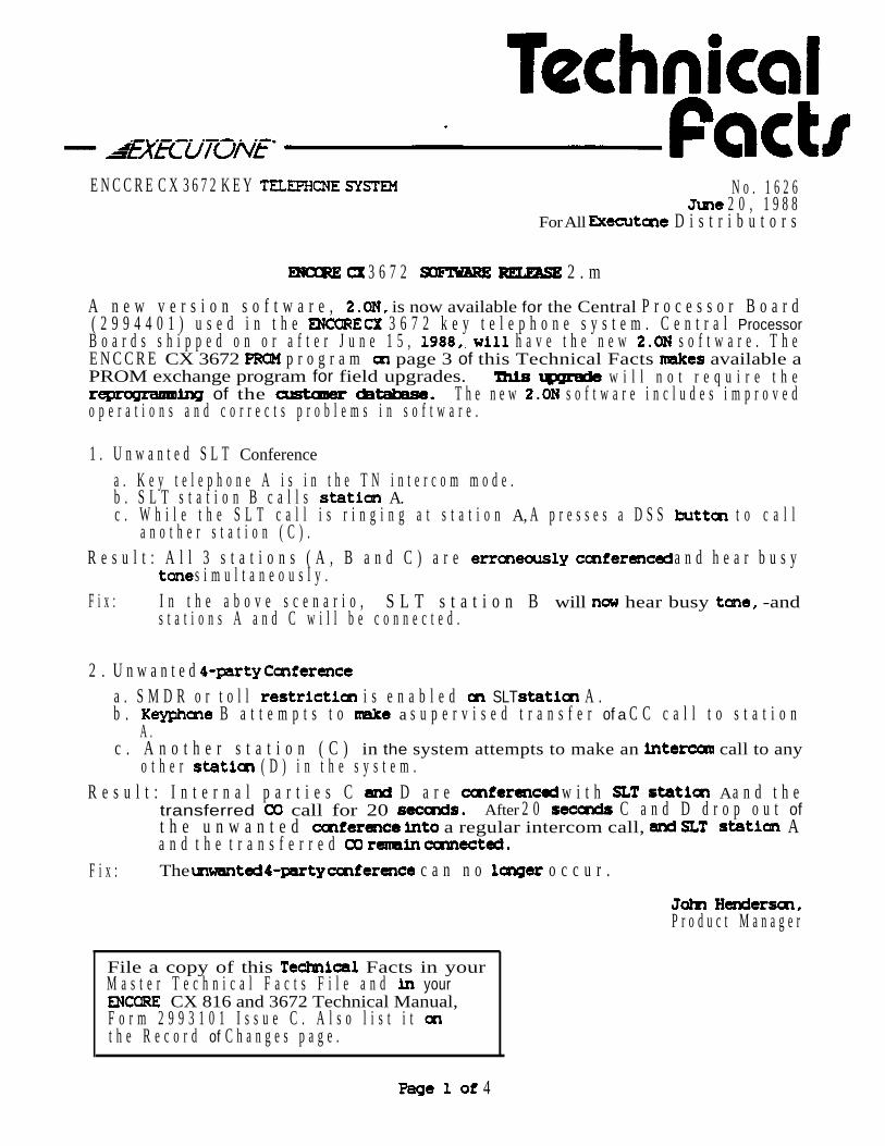
A n e w v e r s i o n s o f t w a r e , is now available for the Central P r o c e s s o r B o a r d( 2 9 9 4 4 0 1 ) u s e d i n t h e 3 6 7 2 k e y t e l e p h o n e s y s t e m . C e n t r a l ProcessorB o a r d s s h i p p e d o n o r a f t e r J u n e 1 5 , h a v e t h e n e w s o f t w a r e . T h eE N C C R E CX 3672 p r o g r a m page 3 of this Technical Facts available aPROM exchange program for field upgrades. w i l l n o t r e q u i r e t h e
of the T h e n e w s o f t w a r e i n c l u d e s i m p r o v e do p e r a t i o n s a n d c o r r e c t s p r o b l e m s i n s o f t w a r e .
1 . U n w a n t e d S L T Conference
a . K e y t e l e p h o n e A i s i n t h e T N i n t e r c o m m o d e .b . S L T s t a t i o n B c a l l s A.c . W h i l e t h e S L T c a l l i s r i n g i n g a t s t a t i o n A, A p r e s s e s a D S S t o c a l l
a n o t h e r s t a t i o n ( C ) .R e s u l t : A l l 3 s t a t i o n s ( A , B a n d C ) a r e a n d h e a r b u s y
s i m u l t a n e o u s l y .F i x : I n t h e a b o v e s c e n a r i o , S L T s t a t i o n B will hear busy -and
s t a t i o n s A a n d C w i l l b e c o n n e c t e d .
2 . U n w a n t e d a . S M D R o r t o l l i s e n a b l e d SLT A .b . B a t t e m p t s t o a s u p e r v i s e d t r a n s f e r of a C C c a l l t o s t a t i o n
A .c . A n o t h e r s t a t i o n ( C ) in the system attempts to make an call to any
o t h e r ( D ) i n t h e s y s t e m .R e s u l t : I n t e r n a l p a r t i e s C D a r e w i t h A a n d t h e
transferred call for 20 After 2 0 C a n d D d r o p o u t oft h e u n w a n t e d a regular intercom call, Aa n d t h e t r a n s f e r r e d
F i x : The c a n n o o c c u r .
P r o d u c t M a n a g e r
File a copy of this Facts in yourM a s t e r T e c h n i c a l F a c t s F i l e a n d your
CX 816 and 3672 Technical Manual,F o r m 2 9 9 3 1 0 1 I s s u e C . A l s o l i s t i t t h e R e c o r d of C h a n g e s p a g e .
4

3 . U n w a n t e d N i g h t R i n g
This problem Is the result of a b y the end user; It is not asoftware failure in t h e system.
a. Attendant A forwards calls to station B.b. m-hook, A mistakenly presses the flashing to cancel call
forward. This operation actually ambles Night Ring; call forward is stillactivated (the correct way to cancel call forward is by pressing theflashing k e y while .
c. If A then goes off-hook and presses the LED goes out.
R e s u l t : The result is not what the end user expects: call forward is but Night Service is still even though there is no visual (LED)
F i x : The LED will lit when the occurs to indicate thesystem is still in Night Service. A then presses whileon-hook to cancel.
Be&use the Is so we offer the following reminder:a. Call Forward: and cancellation by pressing the button
w h i l e o f f - h o o k .b. Night Service: activation and cancellation by the
while
4. Preferred Line Answer For DISA Calls
a. Preferred Line Answer is enabled for A.b. An incoming DISA call rings in A, causing the Loop to
flash.c. A lifts handset to answer the call.
Result: Preferred Line does not the DISA call is notanswered A depresses the f k e y .
Fix: Preferred Line Answer will now f o r calls Simply pick up the handset and speak to the calling party.
P a g e 2 of 4 TF1626

The CX 3672 program offers a of obtaining 2. ONsoftware for you to upgrade your present customers and inventory in stock, ifdesired.Order part A69202 from the Inside Sales Department for the software by setsfor replacement in the field. Part A69202 represents a complete set of six (6)
necessary to change software in one ( 1) system. $115 .OO will be chargedfor each set. Full credit for each set will be given if returnedfollowing the requirements No credit will be issued for any old sets received after the close ofbusiness December 30, 1988.All ENCORE CX Central Processor Boards (2994401) shipped or repaired or afterJune 15, 1988, from our Diego warehouse repair center will have the new
software version included.
To
Please use the following procedure to obtain new sets. The forreturning the old sets, as well as the return location, have changed fromthe last software
Call the Inside Department with a purchase order for part A69202 sets. $115.00 per set will be charged.
2. Upon receiving the new exchange as quickly as possible in desiredCPB (2994401) cards.
3. Call the Inside Sales Department prior to returning the old sets, and obtain a credit authorization
4. Fill out the attached Return Authorization Form and send a copy with theold sets to:
Inc.Attn: Manufacturing8300 East DriveScottsdale, 85260CRA
Do not use the previous Return Form provided with Technical Facts1623 or 1608.
5. Be sure to include the Credit Return the shipping
6. A credit of $115 .OO will be issued for each set returned and passing
TF1626 Page 3 of 4

sets
The following steps should be followed when exchanging on the (2994401).
1. switch 8 the DIP switch of the is in the OFF position. Thiswill protect the customer’s data base.
2 .
3 .
4 .
Turn OFF the power switch the .
Using removal tabs, the card.
Place CPB card, side up, on a well-lighted, clean surface. Make sure to use a static wrist strap to a ground whenhandling the CPB.
5 . Locate six mounted in chip sockets marked G2, 3, 4, 8 and 9.Carefully remove, using an IC remover, old and set aside for properpacking.
6 . Remove the new PROM set from its packing tube and insert each carefully the chip socket using the chip tool. All six are
with a number for matching to a chip socket. Make certain eachPROM is inserted In the proper (pin me to pin me).
7 . Carefully inspect each PROM to ensure it is installed properly without anydamage to gins (pins outside the socket or bent under the device body).
8 .
9 .
Insert the CPB into the system and turn the an.
Press the reset button on the CPB then check for systemoperation.
10. Pack old Into the tube and secure.
NOTE:
Devices received will be screened for physical (bent, broken pins, brokencases, etc.) and to ensure that complete sets are included prior to credit
.
Page 4 of 4 TF1626

ENCORE CX 3672 36112 KEY TELEPHONE SYSTEMS No. 163OADecember
All EXECUTONE Distributors
NEW BOARDS FOR THE ENCORE CX SYSTEM
Two new boards are now available for use in ENCORE CX and key telephone sys-tems. The Single tine OPX board (OPX, 2993706) enables the use of four off-premise 2500telephone sets. The Amplified Central Office board (COB-A, 2993705) enhances audio levels forsystems using and multi-line conference applications.
1. SINGLE LINE OPX BOARD (OPX, 2993706)
The OPX board provides four (4) FCC registered single line interface ports. When anOPX is installed, the maximum number of stations in the system is reduced by four. The OPXboard can be used with a Central Processor Board (CPB) as well as with an Enhanced Proces-sor Board (EPB).
1.1 OPX STATION FEATURES AND
OPX station features are the same as SLT station features. The only exception is “Receiving Mes-sage Waiting- Indication”, which is not allowed. feature operations are identical to those foron-premise SLT stations. Refer to Section 101 of the ENCORE CX Technical Manual (Form2993101 D) for details of allowed features, and refer to Section 201 for instructions.OPX stations cannot answer a message waiting indication since they are incapab e of receivingsuch an indication.
1.2 INFORMATION
Each OPX port requires an network circuit. An FCC interface is re-quired to connect to the network. Onbe used on an OPX circuit provided by the E
SLT devices cap of true DTMF canX system. When an OPX boar8 is installed, four
station ports are rendered unusable, reducing the maximum number of stations in the systemby four (see Example 1).
John Henderson,Product Manager
NOTE: This Technical Facts replaces TF 7630, issued
Page 1 of4

Example OPX Reduces Maximum Number of Stations by 4
An OPX is inserted into the second card slotExt 108 111 support four ( 4 ) OPX circuits
Loop resistance/current: each circuit operates with a loop resistance up to ohms (includ-ing station resistance).Maximum current (terminals shorted) = Mininum current ohms = 20mA.
1.3 INSTALLATION
The OPX board can be installed in all but the first card slot of the ENCORE CX system. It can be inserted and removed with power on. The board has a “NORMAL/SERVICE”switch on its top front edge, as the KIB, SIB and COB cards have. It also has an adjustable con-trol directly above the switch. Do not make adjustment to this control. Itis factory set for proper operation.
One 1 ) Ring Generator Unit (RGU) and one (1port t e OPX card. Refer to the ENCORE CX
Applications Board (APL) are necessary to sup- Manual for An
additional Receiver/Sender Module (RSM) may also be needed if the combined traffic of OPX,SIB, and calls affects the availability of receiver circuits.
A type female connector is provided on the front edge of the OPX. This allowsthe OPX system extensions to be cabled to the Main Distributor Frame Twenty-five (25)pair cabling must be prepared with a male connector to extend the OPX extension to the MDF.The cable should be routed throucabinet. The cable(s) then should
h the bottom cable access area of the KSU or expansion
connector .should be secure
terminated on industry standard punch-downAfter the type cable connector has been attached, the cable
to a cable at the bottom of the KSU or expansion cabinet.
Connection from the OPX punch-down block to an FCC approved connector can be doneby cross-connect wiring. Example 2 illustrates the pair identification for each of the OPX circuits.
1.4 PROGRAMMING
In customer data base entries, all OPX station extensions must be programmed with a stationID code of This is done in “Station Attributes” flash 40, page B. Refer to page 18 of Section700 in the ENCORE CX Technical Manual.
Page 2 of 4
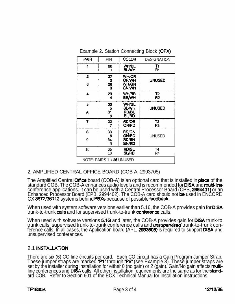
Example 2. Station Connecting Block
PIN DESIGNATION
UNUSED9
910
10 R4 INOTE: PAIRS 1 UNUSED
2. AMPLIFIED CENTRAL OFFICE BOARD (COB-A, 2993705)
The Amplified Central board (COB-A) is an optional card that is installed in of thestandard COB. The COB-A enhances audio levels and is recommended for and conference applications. It can be used with a Central Processor Board (CPB, or anEnhanced Processor Board (EPB, 2994402). The COB-A card should not used in ENCORECX systems behind because of possible
When used with system software versions earlier than 5.16, the COB-A provides gain for trunk-to-trunk and for supervised trunk-to-trunk calls.
When used with software versions and later, the COB-A provides gain for trunk-totrunk calls, supervised trunk-to-trunk conference calls and trunk-to-trunk con-ference calls. In all cases, the Application board (APL, is required to support andunsupervised conferences.
2.1
There are six (6) CO line circuits per card. Each CO circuit has a Gain Program Jumper Strap.These jumper straps are marked through (see Example 3). These jumper straps areset by the installer durinline conferences and
installation for either 0 (no gain) or 2 (gain). Gain/No gain affects DI
ard COB.A calls. All other installation requirements are the same as for the
Refer to Section 601 of the ECX Technical Manual for installation instructions.
Page 3 of 4

Example 3. Jumper Straps on COB-A for Setting Gain/No Gain
0 0 0 (No Gain)
(Sat Gain)
(Gain) 0 0
P2(Sat for no Gain)
.
0 (No Gain)
(Gain)
co Circuit123456
Jumper
PlP 2
P3P4
0 2
Gain Off Gain OnGain On
Gain Off OnGain On
On
1
.
C X K E Y N o . 1 6 3 5S e p t e m b e r 16, 1 9 8 8
F o r A l l D i s t r i b u t o r s
T h e E N C O R E C X L i n e A d a p t e r / O f f P r e m i s e s E x t e n s i o n ( S L A - O P X , 2 9 9 7 3 0 1 ) I sa v a i l a b l e T h i s n e w p r o d u c t I s a s i n g l e a d a p t e r w h i c h p r o v i d e sa n I n t e r f a c e b e t w e e n a n e l e c t r o n i c k e y t e l e p h o n e p o r t a n d m o s t s t a n d a r d D T M Fs i n g l e l i n e t e l e p h o n e s o r d e v i c e s . I t I s d e s i g n e d t o w o r k w i t h t h e ENCOREC X 5 1 2 a n d k e y t e l e p h o n e s y s t e m s .
C a n b e u s e d f o r O f f P r e m i s e s E x t e n s i o n (OPX a p p l i c a t i o n s .S e l f - c o n t a i n e d ; i n c l u d e s I t s o w n p o w e r y a n d r i n g i n g g e n e r a t o r .
e r a t e s o n c o m m o n A C p o w e r .U m o d u l a r f o r e a s y I n s t a l l a t i o n .P r o v i d e s a m e a n s o I n t e r f a c e m a n y s p e c i a l e n t d e v i c e s ( s u c h a sa F A X , modem, c a r d r e a d e r , a u t o a t t e n d a n t o r o h e r t e l e p h o n e - r e l a t e dd e v i c e s ) .
l l i e s w i t h p a r t 1 5 a n d 6 8 o f t h e FCC r e g u l a t i o n s .
A s t a n d a r d D T M F s i n g l e l i n e t e l e p h o n e u s e d w i t h t h e S L A - O P X perform t h ef o l l o w i n g s t a t i o n o p e r a t i o n s :
P l a c e i n t e r c o m a n d o u t s i d e c a l l s .A n s w e r I n t e r c o m a n d o u t s i d e c a l l s .P a r k a n d r e t r i e v e c a l l s I n C a l l P a r k l o c a t i o n sP l a c e a n d r e t r i e v e c a l l s o n S y s t e m H o l d ( 5 1 2
8 1 6 o n l y ) .o n y ) .
M a k e and r e c e i v e s c r e e n e d and u n s c r e e n e d transfers.P e r f o r m a f l a s h o n U s e t h e G r o u p C a l l P i c k u p f e a t u r e ( 8 1 6 U s e t h e C a l l P i c k u p f e a t u r e .U s e t h e C a l l F o r w a r d f e a t u r e .
t o a b u s y A l l o w s t h e o f s y s t e m n i g h t s e r v i c e m o d e .A l l o w s h t p i c k u p of U N A c a l l s ( 8 1 6 .
e r n a l , e x t e r n a l .A l l o w s u s e of t h e M e e t - M e
u s e r - s e l e c t e d d a y / n t
F i l e a c o p y of t h i s F a c t s I ny o u r Master T e c h Facts F i l e . a c o p yI n y o u r E N C O R E C X T e c h n i c a l
a n d I n t h e ENCOREC X 5 1 2 P r o d u c t / T e c h n i c a l M a n u a l , F o r m2 9 8 3 1 0 1 A . A l s o l i s t t h e Record ofChanges pages.
John Henderson,P r o d u c t Manager
P a g e 1 of 3
a.
b.
C .
d.
e.
f.
h.
System and Station
The SLA-OPX cannot
MSG Waiting
Notes
Speed Dial Featureuse or program system or station speed dial bins.
The message waiting feature cannot be used. When a key set calls anunattended SLA-OPX a callback request generated from the key setwill result in a confirmation tone at the key set. No visual Indication,however, will appear at the SLA-OPX station.
Do Not DisturbThe Do Not Disturb feature cannot be activated f r o m a SLA-OPX station.
Call Wait The SLA-OPX station is allowed the call wait (camp-on) feature. The OPX station user can dial 3 a n d c a m p - o n t o a b u s y s t a t i o n .
Answering a Call Wait
A key set Is allowed t o c a m p - o n t o a b u s y SLA-OPX s t a t i o n . T h e c a m p e d - o ns t a t i o n will ring the SLA-OPX as soon it goes on-hook. The SLA-OPX
will not receive a tone. This is a “Data Security”feature.
Conference
The SLA-OPX can be included In a ccmference, but cannot Initiate aconference .
CO Line Access
The ENCORE CX 512 with software or lower does not allow the dial9 code for pooled group access. This restricts the SLA-OPX f r o mhaving the 9 Line selection is allowed by the access code for the Individual CO by
Example: 1. Lift handset (hear tone).2. Dial 8801 (you are to CO 1).
If CO line 1 is In use or no appearance Is assigned, error tone Is heard.When the SLA-OPX is used on the 816, will betranslated as if you have pushed the first feature key cm a means that whatever CO line or allowed system feature is forthat key will be connected or performed.
Retrieving Calls Hold
In ENCORE 512 systems, the S L A - O P X station cannot retrieve calls that have placed on system hold.
Page 2 of 3 TF1635
T h e S L A - O P X i n t e r a c t s with " S t a t i o n T h e S L A - O P X w i l l h a v e a c c e s st o C O l i n e s b a s e d o n t h e d a t a e n t e r e d i n t h e " S t a t i o n A t t r i b u t e s " ( F L A S H 4 0 ) oft h e e x t e n s i o n t o w h i c h i t i s c o n n e c t e d .
T h e S L A - O P X w i l l o p e r a t e as d e s c r i b e d i n the " P r o c t o r S y s t e m P r a c t i c e " O P X w i t h o n l y o n e c h a n g e t o “Default Settings” of the “Station Attributes” of the
T h e o n " P a c e A” 5” of the program for t h ea s s i g n e d m u s t b e c h a n g e d t o 0 .
serviceT h e SLA-OPX is s h i p p e d w i t h i t s o w n P r o d u c t / T e c h n i c a l M a n u a l . T h e m a n u a li n c l u d e s s e c t i o n s c o v e r i n g i n s t a l l a t i o n , f u n c t i o n a l t e s t i n g , f e a t u r eo p e r a t i o n a n d m u c h m o r e .
T h i s u n i t i s m a n u f a c t u r e d b y P r o c t o r A s s o c i a t e s f o r I n f o r m a t i o nS y s t e m s . I n a n d o u t o f w a r r a n t y r e p a i r c a n b e o b t a i n e d d i r e c t l y from P r o c t o r A s s o c i a t e s . D e f e c t i v e S L A - O P X u n i t s b e s h i p p e d p r e - p a i d t o :
P r o c t o r A s s o c i a t e s1 5 0 5 0 N . E . 3 6 t h
W a s h i n g t o n 9 8 0 5 2
T o o b t a i n a R e t u r n A u t h o r i z a t i o n , c o n t a c t P r o c t o r ' s C u s t o m e r S e r v i c e g r o u p a t206-881-7000 . R e p a i r s are n o r m a l l y p r o c e s s e d i n t w o weeks.
T e c h n i c a l S u p p o r t w i l l be p r o v i d e d b y E X E C U T C N E S y s t e m ' s F i e l dS e r v i c e D e p a r t m e n t i n S c o t t s d a l e , C a l l l - 8 0 0 - 3 5 6 - 7 2 7 9 f o r t o l l freea s s i s t a n c e .
Crders for t h e ENCORE CX SLA-OPX (2997301) Single L i n e Adapter/Off PremisesE x t e n s i o n m u s t be placed with the E X E C U T O N E Customer S e r v i c e / I n s i d e S a l e sD e p a r t m e n t . When placing by call t o l l f r e e l - 8 0 0 - 4 5 1 - 1 7 5 4 . B yFAX call toll free l-800-458-4799. Orders by should be sent to:
E X E C U T O N E Information Systems, Inc.8300 E. Dr.Scottsdale, AZ 85260Attention: Customer Service/Inside Sales
Page 3 of 3
ENCORE CX 816 Key Telephone System No. 1637October 14, 1988
For All EXECUTONE Distributors
ENCORE CX 816 UPGRADE EXTENSION
On May 3, 1988, Technical Facts 1624A announced the release of new software versions for PM-1 (2993601) and for PM-2 (2993692). A software upgrade program permitted
older software to be sent to the San Diego repair center for an upgrade, free of charge, ifreceived before September 1988.
We are pleased to announce that the software upgrade program has been extended untilDecember 30, 1986. Rework will be implemented for all program modules containing oldsoftware that are received before December 30, 1988.
How To Return PM-1 (2993601) and PM-2 (2993602) For Rework
Modules for upgrading should be returned to the San Diego repair center. Follow the normalfactory repair procedure, and write “ECX 816 Software Upgrade Program” in the problemdescription section.
1.
2.
3.
4.
Installing Updated Modules at Customer Sites
Customer data forms must reflect the correct customer database. be necessary re-enter customer program data.
Remove AC power.
Remove the old program data module and install the new module. Refer to installationprocedures in the ENCORE CX 818 3672 Technical Manual, Form 2993101.
Restore AC power. Follow the instructions detailed in the ENCORE CX 816 & 3672Technical Manual for initialization and programming.
File a copy of this Technical Facts inyour Master Technical Facts file and inyour ENCORE CX 818 813672 TechnicalManual, Form 2993101 A, C D. Alsolist it on your Record Of Changes page.
John Henderson,Product Manager

ENCORE CX 816 Key Telephone System No. 1637October 14, 1988
For All EXECUTONE Distributors
ENCORE CX 816 UPGRADE EXTENSION
On May 3, 1988, Technical Facts announced the release of new software versions for PM-1 (2993601) and for PM-2 (2993602). A software upgrade program permitted
older software to be sent to the San Diego repair center for an upgrade, free of charge, ifreceived before September 1988.We are pleased to announce that the software upgrade program has been extended untilDecember 30, 1988. Rework will be implemented for all program modules containing oldsoftware that are received before December 30, 1988.
How To Return PM-1 (2993601) and PM-2 (2993602) For Rework
Modules for upgrading should be returned to the San Diego repair center. Follow the normalfactory repair procedure, and write “ECX 816 Software Upgrade Program” in the problemdescription section.
1.
2.
3.
4.
Installing Updated Modules at Customer Sites
Customer data forms must reflect the correct customer database. necessary customer program
Remove AC power.Remove the old program data module and install the new module. Refer to installationprocedures in the ENCORE CX 816 3672 Technical Manual, Form 2993101.Restore AC power. Follow the instructions detailed in the ENCORE CX 816 & 3672Technical Manual for initialization and programming.
John Henderson,Product Manager
File a copy of this Technical Facts inyour Master Technical Facts file and inyour ENCORE CX 816 3672 TechnicalManual, Form 2993101 A, C & D. Alsolist it on your Record Of Changes page.

1.3 GROUP (Feature Package 5
This method is particularly useful for high traffic offices. One of the 8 UCD groups on the EN-CORE system can be set up with several automated attendants. The UCD group isprogrammed with the SLT port or ports as the only UCD group members. The desired CO linesare programmed to ring this UCD group. The call wilt be circulated within the UCD group untilan available automated attendant is found. This automated attendant is then rung. One stationport is required for each automated attendant.
2. SETUP
2.1 PRESET CALL FORWARDING
An unequipped key telephone port is assigned in the database to ring on the desired CO lines.This port is then programmed to preset forward to the SLT port where the automated attendantis connected (FLASH 40, Page B, Button 6). The Preset Forward Timer (FLASH 04) must be setin programming. It should be set at approximately 5 seconds depending on customer needs.This same timer is used to determine the amount of time before the first automated attendantforwards to the second automated attendant if more than one attendant is used.
2.2 STATION CALL FORWARDING
A key telephone is dedicated for automated attendant use. Desired CO lines will ring this sta-tion which is placed in station call forward mode to forward calls immediately to the SLT portwhere the automated attendant is connected.
2.3 UCD GROUP
The UCD group is programmed with the station numbers of the SLT ports to which an automatedattendant is connected (FLASH 38). Any or all CO lines can be assigned (FLASH 30, Button 9)to ring directly into the UCD group.
3. INSTALLING THE AUTOMATED ATTENDANT
l Connect the AC power cord to the Receptionist and plug the cord into anAC receptacle.
Connect the Single Line Telephone line cord to the “to line” jack on the back of the Receptionist.
l The Single tine Telephone may be connected to the the Receptionist if desired to act as busy ove
hone” jack on the back ofow station.
There are 4 switches on the back of the COBOTYX Receptionist. If the ENCORE CXkey telephone system does not have system battery back up, switches 1 and 2 shouldbe and switches 3 and 4 should be OFF (up).
l If the ENCORE CX system does have system battery back up, switches 2 and 3should be ON (down) switch 4 should be OFF (up).
Consult the Receptionist manual for setting up greeting voice messagesand programming the unit for call routing within the ENCORE CX system.
1 Page 2 of 2

ENCORE CX 816 SECTION 100KEY TELEPHONE SYSTEM ISSUE 2, NOVEMBER 1 9 8 8
ENCORE CX 816 SYSTEM DESCRIPTION AND FEATURES
TABLE Of CONTENTS
PAGE1. INTRODUCTION . . . . . . . . . . . . . . . . . . . . . . . . . . . . . . . . . . . . . . . . . . . . . . . . . . . . . . . . . . 1
2. SYSTEM DESCRIPTION . . . . . . . . . . . . . . . . . . . . . . . . . . . . . . . . . . . . . . . . . . . . . . . . , . .
3. EQUIPMENT DESCRIPTION3.1 KEY SERVICE UNIT (KSU) . . . . . . . . . . . . . . . . . . . . . . . . . . . . . . . . . . . . . . . . .3.2 KEYTELEPHONE . . . . . . . . . . . . . . . . . . . . . . . . . . . . . . . . . . . . . . . . . . . . . . . . . . 33.3 PHONE BOX . . . . . . . . . . . . . . . . . . . . . . . . . . . . . . . . . . . . . . . . . . . . . . . . . . . . . . 33.4 . . . . . . . . . . . . . . . . . . . . . . . . . . . . . . . . . . . . . . . . . . . . . . . 33.5 EXPANSION MODULE. . . . . . . . . . . . . . . . . . . . . . . . . . . . . . . . . . . . . . . . . . . . .
4 OPTIONAL EQUIPMENT4.1 PORT FOR SMDR . . . . . . . . . . . . . . . . . . . . . . . . . . . . . . . . . . . . . . . . . 34.2 REAL TIME CLOCK . . . . . . . . . . . . . . . . . . . . . . . . . . . . . . . . . . . . . . . . . . . . . . . . 34.3 BACKUP UNIT. . . . . . . . . . . . . . . . . . . . . . . . . . . . . . . . . . . . . . . . . . .
5. SYSTEM FEATURES5.01 ALARM . . . . . . . . . . . . . . . . . . . . . . . . . . . . . . . . . . . . . . . . . . . . . . . . . . . . . . . . . . . 45.02 ATTENDANT RECALL. . . . . . . . . . . . . . . . . . . . . . . . . . . . . . . . . . . . . . . . . . . . . . . 45.03 AUTOMATIC PAUSE INSERTION WITH SPEED . . . . . . . . . . . . . . . . . . . . 45.04 AUTOMATIC PRIVACY. . . . . . . . . . . . . . . . . . . . . . . . . . . . . . . . . . . . . . . . . . . . . . 45.05 BACKUP-MEMORY . . . . . . . . . . . . . . . . . . . . . . . . . . . . . . . . . . . . . . . 45.06 BACKUP-SYSTEM . . . . . . . . . . . . . . . . . . . . . . . . . . . . . . . . . . . . . . . . . 45.07 CO ACCESS . . . . . . . . . . . . . . . . . . . . . . . . . . . . . . . . . . . . . . . . . . . . . . . . . 45.08 CO LINE GROUPS . . . . . . . . . . . . . . . . . . . . . . . . . . . . . . . . . . . . . . . . . . . . . . . . . 45.09 CO RING DETECT . . . . . . . . . . . . . . . . . . . . . . . . . . . . . . . . . . . . . . . . . . . . . . . . . 45.10 DIAL PULSE SENDING. . . . . . . . . . . . . . . . . . . . . . . . . . . . . . . . . . . . . . . . . . . . . . 45.11 DIALING PRIVILEGES . . . . . . . . . . . . . . . . . . . . . . . . . . . . . . . . . . . . . . . . . . . . . . . 45.12 DTMF SENDING . . . . . . . . . . . . . . . . . . . . . . . . . . . . . . . . . . . . . . . . . . . . . . . . . . . . 45.13 EMERGENCY TRANSFER. . . . . . . . . . . . . . . . . . . . . . . . . . . . . . . . . . . . . . . . . . . 45.14 FLASH WITH SPEED DIAL . . . . . . . . . . . . . . . . . . . . . . . . . . . . . . . . . . . . . . . . . . 45.15 FLEXIBLE . . . . . . . . . . . . . . . . . . . . . . . . . . . . . . . . . . . . . . . . . . . . . 45.16 HOLD PREFERENCE. . . . . . . . . . . . . . . . . . . . . . . . . . . . . . . . . . . . . . . . . . . . . . . 45.17 HUNTGROUPS . . . . . . . . . . . . . . . . . . . . . . . . . . . . . . . . . . . . . . . . . . . . . . . . . . . .5.10 LOUD BELL CONTROL . . . . . . . . . . . . . . . . . . . . . . . . . . . . . . . . . . . . . . . . . . . . . 55.19 MUSIC ON HOLD . . . . . . . . . . . . . . . . . . . . . . . . . . . . . . . . . . . . . . . . . . . . . . . . . . 55.20 NIGHT TRANSFER . . . . . . . . . . . . . . . . . . . . . . . . . . . . . . . . . . . . . . . . . . . . . . . . .5.21 OUTSIDE LINE RING ASSIGNMENT. . . . . . . . . . . . . . . . . . . . . . . . . . . . . . . . . . .5.22 PAUSE TIMER. . . . . . . . . . . . . . . . . . . . . . . . . . . . . . . . . . . . . . . . . . . . . . . . . . . . . 55.23 PBX DIAL CODES. . . . . . . . . . . . . . . . . . . . . . . . . . . . . . . . . . . . . . . . . . . . . . . . 55.24 PULSE-TO-TONE SWITCHOVER . . . . . . . . . . . . . . . . . . . . . . . . . . . . . . . . . . . .
100-A
SECTION 100 ENCORE CX 816 SYSTEM DESCRIPTION AND FEATURESISSUE 2, NOVEMBER 1988
TABLE OF CONTENTS (CONT’D)
DESCRIPTION PAGE
5.25 REAL TIME CLOCK . . . . . . . . . . . . . . . . . . . . . . . . . . . . . . . . . . . . . . . . . . . . . . . 55.26, SMDR . . . . . . . . . . . . . . . . . . . . . . . . . . . . . . . . . . . . . . . . . . . . . . . . . . . . . . . . . . . 55.27 SYSTEM SPEED DIAL . . . . . . . . . . . . . . . . . . . . . . . . . . . . . . . . . . . . . . . . . . . . . 5
6. STATION FEATURES6.016.026.036.046.056.066.076.086.096.106.116.126.136.146.156.166.176.186.196.206.216.226.236.246.256.266.276.286.296.306.316.326.336.346.356.36
ADD ON CONFERENCE . . . . . . . . . . . . . . . . . . . . . . . . . . . . . . . . . . . . . . . . . . . 5AUTOMATIC SELECTION . . . . . . . . . . . . . . . . . . . . . . . . . . . . . . . . . . . . . . . . . . 5BACKGROUND MUSIC . . . . . . . . . . . . . . . . . . . . . . . . . . . . . . . . . . . . . . . . . . . . 5CALL ANNOUNCE-PRIVACY. . . . . . . . . . . . . . . . . . . . . . . . . . . . . . . . . . . . . . . . 6CALL PARK . . . . . . . . . . . . . . . . . . . . . . . . . . . . . . . . . . . . . . . . . . . . . . . . . . . . . . 6CALL TRANSFER . . . . . . . . . . . . . . . . . . . . . . . . . . . . . . . . . . . . . . . . . . . . . . . . .CALL WAITING . . . . . . . . . . . . . . . . . . . . . . . . . . . . . . . . . . . . . . . . . . . . . . . . . . .DIRECT STATION SELECTION . . . . . . . . . . . . . . . . . . . . . . . . . . . . . . . . . . . . . . 6DIRECTED CALL PICKUP . . . . . . . . . . . . . . . . . . . . . . . . . . . . . . . . . . . . . . . . . .DISPLAY CAPABILITIES . . . . . . . . . . . . . . . . . . . . . . . . . . . . . . . . . . . . . . . . . . . . 6
. . . . . . . . . . . . . . . . . . . . . . . . . . . . . . . . . . . . . . . . . . . . . . . .EXCLUSIVE HOLD . . . . . . . . . . . . . . . . . . . . . . . . . . . . . . . . . . . . . . . . . . . . . . . .
TRANSFER. . . . . . . . . . . . . . . . . . . . . . . . . . . . . . . . 6FLASH KEY . . . . . . . . . . . . . . . . . . . . . . . . . . . . . . . . . . . . . . . . . . . . . . . . . . . . . .FLEXIBLE ASSIGNMENT. .. . . . . . . . . . . . . . . . . . . . . . . . . . . . . . . 6GROUP CALL PICKUP. . . . . . . . . . . . . . . . . . . . . . . . . . . . . . . . . . . . . . . . . . . . . 7HANDSFREE ANSWERBACK. . . . . . . . . . . . . . . . . . . . . . . . . . . . . . . . . . . . . . . 7HOLDRECALL . . . . . . . . . . . . . . . . . . . . . . . . . . . . . . . . . . . . . . . . . . . . . . . . . . . 7INTERCOM SIGNALING SELECT. . . . . . . . . . . . . . . . . . . . . . . . . . . . . . . . . . . 7
NUMBER . . . . . . . . . . . . . . . . . . . . . . . . . . . . . . . . . . . . . . . . . . . 7MEET ME PAGE . . . . . . . . . . . . . . . . . . . . . . . . . . . . . . . . . . . . . . . . . . . . . . . . . . 7MESSAGE WAITING. . . . . . . . . . . . . . . . . . . . . . . . . . . . . . . . . . . . . . . . . . . . . . . 7MESSAGE REMINDER TONE. . . . . . . . . . . . . . . . . . . . . . . . . . . . . . . 7MULTI-UNE CONFERENCE . . . . . . . . . . . . . . . . . . . . . . . . . . . . . . . . . . . . . . . . 7ON-HOOK DIALING . . . . . . . . . . . . . . . . . . . . . . . . . . . . . . . . . . . . . . . . . . . . . . 7PAGING . . . . . . . . . . . . . . . . . . . . . . . . . . . . . . . . . .. . . . . . . . . . . . . . . . . . . . . . . 7PAGING ACCESS RESTRICTION . . . . . . . . . . . . . . . . . . . . . . . . . . . . . . . . . . . . 7PRE-SELECTED MESSAGES . . . . . . . . . . . . . . . . . . . . . . . . . . . . . . . . . . . . . . . 8PRESET CALL FORWARD. . . . . . . . . . . . . . . . . . . . . . . . . . . . . . . . . . . . . . . . . .QUEUING. . . . . . . . . . . . . . . . . . . . . . . . . . . . . . . . . . . . . . . . . . . . . . . . . . . . . . . .RINGING UNE ANSWER . . . . . . . . . . . . . . . . . . . . . . . . . . . . . . . . . . . . . . . . . . .SAVE NUMBER . . . . . . . . . . . . . . . . . . . . . . . . . . . . . . . . . . . . . . . . . . . .STATION CALL FORWARD . . . . . . . . . . . . . . . . . . . . . . . . . . . . . . . . . . . . . . . . . 0STATION SPEED DIAL . . . . . . . . . . . . . . . . . . . . . . . . . . . . . . . . . . . . . . . . . . . . .SYSTEM HOLD. . . . . . . . . . . . . . . . . . . . . . . . . . . . . . . . . . . . . . . . . . . . . . . . . . .SPEAKERPHONES . . . . . . . . . . . . . . . . . . . . . . . . . . . . . . . . . . . . . . . . . . . . . . . 0
100-B
ENCORE 816 SYSTEM DESCRIPTION AND FEATURES SECTION ISSUE 3, NOVEMBER 1989
TABLE OF CONTENTS (CONT’D)
7.
8.
9.
10.
11.
12
13.
14.
15.
DESCRIPTION PAGE
FEATURE INDEX . . . . . . . . . . . . . . . . . . . . . . . . . . . . . . . . . . . . . . . . . . . . . . . . . . . .
FEATURES AND BENEFITS8.1 SYSTEM FEATURES . . . . . . . . . . . . . . . . . . . . . . . . . . . . . . . . . . . . . . . . . . 118.2 STATION FEATURES . . . . . . . . . . . . . . . . . . . . . . . . . . . . . . . . . . . . . . . . .
PROGRAM MODULE 3 SOFTWARE . . . . . . . . . . . . . . . . . . . . . . . . . . . . . . . . . . . .
PM-3: STATION FEATURES10.1 AUTOMATIC RELEASE OF THE MONITOR . . . . . . . . . . . . . . . . 1810.2 AUTOMATIC . . . . . . . . . . . . . . . . . . . . . . . . . . . . . . . . . . . .10.3 CALL FORWARD BUSY/NO ANSWER . . . . . . . . . . . . . . . . . . . . . . . . . . .10.4 CANNED TOLL RESTRICTION . . . . . . . . . . . . . . . . . . . . . . . . . . . . . . . . .10.510.6 FLASH ON INTERCOM CALLS . . . . . . . . . . . . . . . . . . . . . . . . . . . . . . . . .10.7 INTERCOM CALL HOLD . . . . . . . . . . . . . . . . . . . . . . . . . . . . . . . . . . . . . . . . lS10.8 ONE-TIME DO NOT DISTURB (DND) . . . . . . . . . . . . . . . . . . . . . . . . . . . .10.9 . . . . . . . . . . . . . . . . . . . . .10.10 PROGRESS TONES ON HANDSFREE ANSWERBACK . . . . . . . . . . . . . .10.11 RECALLRING.. . . . . . . . . . . . . . . . . . . . . . . . . . . . . . . . . . . . . . . . . . . . .
PM-3: ATTENDANT FEATURES11.1 DISABLING OUTGOING ACCESS . . . . . . . . . . . . . . . . . . . . . . . . . . . . . . .11.2 SELECTING BGM AT A PHONE BOX FROM ATTENDANT . . . . . . . . . . .
PM-3: INTERCOM PHONE BOX 12.1 BLOCKING BACKGROUND MUSIC (BGM)
PROGRAM MODULE . . . . . . . . . . . . . . . . . . . . . . . . . . . . . . .
SYSTEM FEATURES14.1 ENHANCED KEY TELEPHONE COMPATIBILITY . . . . . . . . . .
STATION FEATURES15.1 ADDITIONAL DIAL CODES . . . . . . . . . . . . . . . . . . . . . . . . . . . . . . . . . . . . .15.2 ADDITIONAL PROGRAMMING CODES.15.3 TRANSFER SEARCH WITH RECOVERY .....................................................15.4 ABBREVIATED CONFERENCE . . . . . . . . . . . . . . . . . . . . . . . . . . . . . . . . .
LIST OF FIGURES
1. ENCORE CX 818 KEY SERVICE UNIT2. ENCORE CX KEY TELEPHONES . . . . . . . . . . . . . . . . . . . . . . . . . . . . . . . .
100-c

ENCORE CX 816 SECTION 100KEY TELEPHONE SYSTEM ISSUE 2, NOVEMBER 1988
SYSTEM DESCRIPTION AND FEATURES
1. INTRODUCTIONThe ENCORE CX Key Telephone Systems aredesigned to meet the needs of telephone users fromsmall to large. The systems are designed for growthby allowing the same telephones to be used in allsystems. The low end system (CX 816) is a flat packsystem equipped with 4 CO lines and 8 stations.It can be easily expanded to 8 lines and 16 stationswith a modular PCB mounted in the KSU.The mid-range system (CX 3672) is a KTU card) system that can support a maximum of 36 linesand 72 stations. This system is expanded withplug-in cards and a modular shelf. Except wherespecifically identified, the features will operate thesame in all systems.
2. SYSTEM DESCRIPTIONThe ENCORE CX 816 Key Telephone Systemis designed to meet the telecommunications needsof small to medium sized businesses. A customermay start out with only a few outside lines andstations and can add as the business grows up toa maximum of 8 lines and 16 stations.This system contains all the features of the biggersystem with the exception of Off-Hook VoiceAnnounce, single line compatibility, DSS console,unsupervised conference, and (Direct InwardSystem Access). In addition, the ENCORE CX 816has an alarm feature which is not provided in thebigger system.
Some of the time and money saving features in theENCORE CX systems include: an adjustable character, 2-line LCD display which allows the userto position it for better viewing; the ability to programa name into the display instead of just using a stationnumber; pre-selected messages which can beviewed on the display; time and date in the display;and the use of the display in on-line programming ofsystem data base.Other features included in the new ENCORE CXsystems are: flexible buttons which allow the user toprogram his/her own telephone; outside line
appearances which can be programmed in anyorder; speakerphone included in all key telephones:unlimited DSS capability; preset call forward so that
a telephone which is busy or does not answer canhave CO calls automatically forwarded to anotherstation; an intercom selector switch which allows theuser to determine the mode of incoming intercomcalls: the ability to restrict a station from accessingfeatures such as paging, DND, call forward andOff -Hook Voice Announce: executive/secretary pairsand hunt groups, and many more features.
100-l
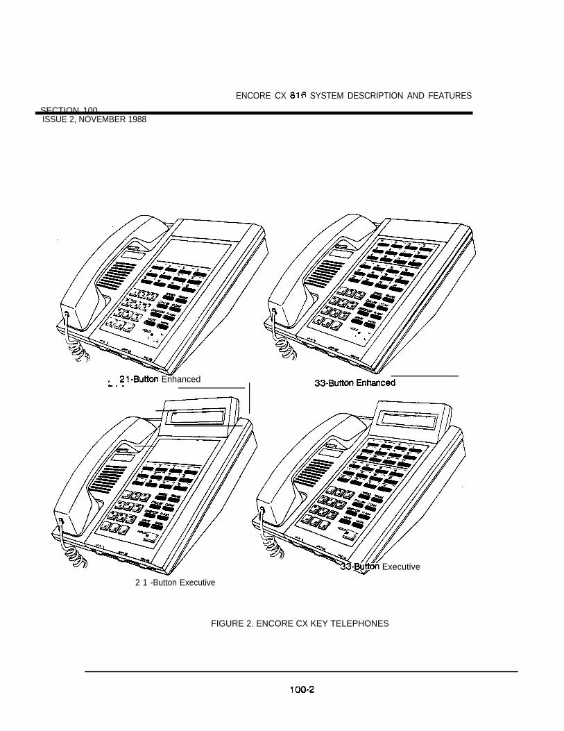
SECTION 100
ENCORE CX SYSTEM DESCRIPTION AND FEATURES
ISSUE 2, NOVEMBER 1988
Enhanced
Executive
2 1 -Button Executive
FIGURE 2. ENCORE CX KEY TELEPHONES
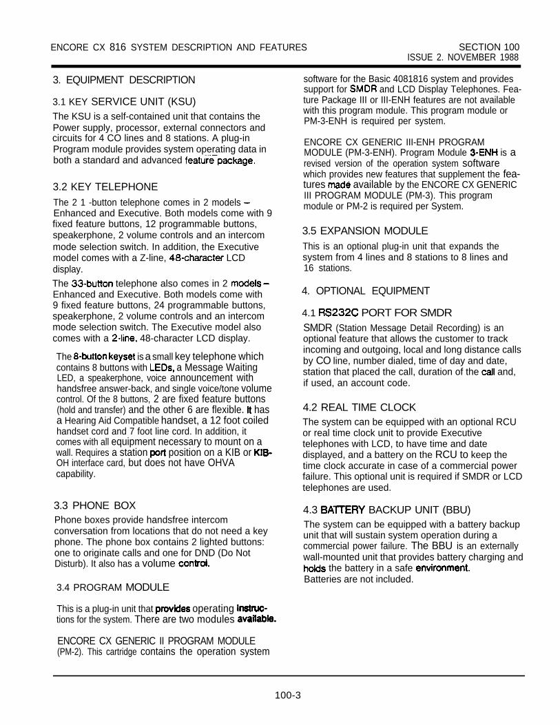
ENCORE CX 816 SYSTEM DESCRIPTION AND FEATURES SECTION 100ISSUE 2. NOVEMBER 1988
3. EQUIPMENT DESCRIPTION
3.1 KEY SERVICE UNIT (KSU)The KSU is a self-contained unit that contains thePower supply, processor, external connectors andcircuits for 4 CO lines and 8 stations. A plug-inProgram module provides system operating data inboth a standard and advanced
3.2 KEY TELEPHONEThe 2 1 -button telephone comes in 2 models Enhanced and Executive. Both models come with 9fixed feature buttons, 12 programmable buttons,speakerphone, 2 volume controls and an intercommode selection switch. In addition, the Executivemodel comes with a Z-line, LCDdisplay.The telephone also comes in 2 Enhanced and Executive. Both models come with9 fixed feature buttons, 24 programmable buttons,speakerphone, 2 volume controls and an intercommode selection switch. The Executive model alsocomes with a 48-character LCD display.
The is a small key telephone whichcontains 8 buttons with a Message WaitingLED, a speakerphone, voice announcement withhandsfree answer-back, and single voice/tone volumecontrol. Of the 8 buttons, 2 are fixed feature buttons(hold and transfer) and the other 6 are flexible. hasa Hearing Aid Compatible handset, a 12 foot coiledhandset cord and 7 foot line cord. In addition, itcomes with all equipment necessary to mount on awall. Requires a station position on a KIB or OH interface card, but does not have OHVAcapability.
3.3 PHONE BOXPhone boxes provide handsfree intercomconversation from locations that do not need a keyphone. The phone box contains 2 lighted buttons:one to originate calls and one for DND (Do NotDisturb). It also has a volume
3.4 PROGRAM MODULE
This is a plug-in unit that operating tions for the system. There are two modules
ENCORE CX GENERIC II PROGRAM MODULE(PM-2). This cartridge contains the operation system
software for the Basic 4081816 system and providessupport for and LCD Display Telephones. Fea-ture Package III or III-ENH features are not availablewith this program module. This program module orPM-3-ENH is required per system.
ENCORE CX GENERIC III-ENH PROGRAMMODULE (PM-3-ENH). Program Module is arevised version of the operation system softwarewhich provides new features that supplement the fea-tures available by the ENCORE CX GENERICIII PROGRAM MODULE (PM-3). This programmodule or PM-2 is required per System.
3.5 EXPANSION MODULEThis is an optional plug-in unit that expands thesystem from 4 lines and 8 stations to 8 lines and16 stations.
4. OPTIONAL EQUIPMENT
4.1 PORT FOR SMDRSMDR (Station Message Detail Recording) is anoptional feature that allows the customer to trackincoming and outgoing, local and long distance callsby CO line, number dialed, time of day and date,station that placed the call, duration of the and,if used, an account code.
4.2 REAL TIME CLOCKThe system can be equipped with an optional RCUor real time clock unit to provide Executivetelephones with LCD, to have time and datedisplayed, and a battery on the RCU to keep thetime clock accurate in case of a commercial powerfailure. This optional unit is required if SMDR or LCDtelephones are used.
4.3 BACKUP UNIT (BBU)The system can be equipped with a battery backupunit that will sustain system operation during acommercial power failure. The BBU is an externallywall-mounted unit that provides battery charging and
the battery in a safe Batteries are not included.
100-3
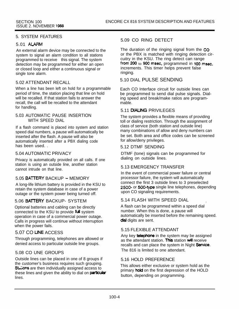
SECTION 100 ENCORE CX 816 SYSTEM DESCRIPTION AND FEATURESISSUE 2. NOVEMBER
5. SYSTEM FEATURES
5.01 An external alarm device may be connected to thesystem to signal an alarm condition to all stationsprogrammed to receive this signal. The systemdetection may be programmed for either an openor closed loop and either a continuous signal orsingle tone alarm.
5.02 ATTENDANT RECALLWhen a line has been left on hold for a programmableperiod of time, the station placing that line on holdwill be recalled. If that station fails to answer therecall, the call will be recalled to the attendantfor handling.
5.03 AUTOMATIC PAUSE INSERTIONWITH SPEED DIAL
If a flash command is placed into system and stationspeed dial numbers, a pause will automatically beinserted after the flash. A pause will also beautomatically inserted after a PBX dialing codehas been used. .
5.04 AUTOMATIC PRIVACYPrivacy is automatically provided on all calls. If onestation is using an outside line, another stationcannot intrude on that line.
5.05 BACKUP MEMORYA long-life lithium battery is provided in the KSU toretain the system database in case of a poweroutage or the system power being turned off.
5.06 BACKUP- SYSTEMOptional batteries and cabling can be directlyconnected to the KSU to provide systemoperation in case of a commercial power outage.Calls in progress will continue without interruptionwhen the power fails.
5.07 CO ACCESSThrough programming, telephones are allowed ordenied access to particular outside line groups.
5.08 CO UNE GROUPSOutside lines can be placed in one of 8 groups ifthe customer’s business requires such grouping.
are then individually assigned access tothese lines and given the ability to dial on lines.
5.09 CO RING DETECT
The duration of the ringing signal from the or the PBX is matched with ringing detection cir-cuitry in the KSU. The ring detect can range
to programmed in increments. This timer helps prevent falseringing.
5.10 DIAL PULSE SENDING
Each CO Interface circuit for outside lines canbe programmed to send dial pulse signals. Dial-ing speed and break/make ratios are program-mable.
5.11 PRIVILEGESThe system provides a flexible means of providingtoll or dialing restriction. Through the assignment ofclass of service (both station and outside line)many combinations of allow and deny numbers canbe set. Both area and office codes can be screenedfor allow/deny privileges.
5.12 DTMF SENDINGDTMF (tone) signals can be programmed fordialing on outside lines.
5.13 EMERGENCY TRANSFERIn the event of commercial power failure or centralprocessor failure, the system will automaticallyconnect the first 3 outside lines to 3 preselected
or single line telephones, dependingupon CO signaling requirements.
5.14 FLASH WITH SPEED DIALA flash can be programmed within a speed dialnumber. When this is done, a pause willautomatically be inserted before the remaining speed.
digits are sent.
5.15 FLEXIBLE ATTENDANTAny key in the system may be assignedas the attendant station. station receiverecalls and can place the system in Night The 816 is limited to one attendant.
5.16 HOLD PREFERENCEThis allows either exclusive or system hold as theprimary on the first depression of the HOLDbutton, depending on programming.
100-4

816 SYSTEM AND FEATURES SECTION ISSUE 2, NOVEMBER
5.17 HUNT GROUPS
Intercom and transferred outside calls can besent to the pilot extension number of a huntgroup. There are 8 hunt groups and each canhave up to 8 stations as members. The systemwill search sequentially (in the order the sta-tions were entered in programming) for an idlestation in and will ring that station.
5.18 LOUD BELL CONTROL
Two sets of relay-controlled contacts are provid-ed to connect external signailing devices. Eachset of contacts can be programmed to followthe ringing signals at any station.
5.19 MUSIC ON HOLDA music source, when connected to the will provide music to all lines on hold.
5.20 NIGHT TRANSFERThe system can be placed into night service. Thisallows designated stations to ring at night that mayor may not ring on those lines during the day.The attendant station can place the system into andrelease frdm night service operation by pressing .the DND button. Any key telephone can place thesystem into and release from night service by dialingcode
5.21 OUTSIDE RING ASSIGNMENTOutside lines are assigned to ring at individualstations by programming. Any station may beprogrammed to ring for any outside line(s) during theDay and/or Night Mode, both or neither.
5.22 PAUSE TIMERWhen dialing a speed number, a timed pausebetween digit sending can be placed in thenumber. The length of this pause can be pro-grammed in the system database.
5.23 PBX DIAL CODES system will allow 5 one- or two-digit access
codes to be entered into memory. When one ofthese codes is dialed, this signals the KSU that tollrestriction is to be applied at the next dialed digitsafter the code. If one of these codes is not dialed,toll restriction does not apply. This allows the dialingof extensions 100, 110, 111, etc.NOTE: The line must be marked as PBX and
toll restriction must be enabled.
5.24 PULSE-TO-TONE When commanded, the system will change thesignaling on an outside line from dial pulse to (tone), allowing the use of common carriers behinda dial pulse outside line. This can be done manuallywhen dialing, Of can be stored within a speed dialnumber.
5.25 REAL TIME CLOCKThis hardware option allows the system time anddate to keep functioning in the event of a commercialpower failure. It also provides the time source forinformation used by display phones and
5.26 SMDR (STATION MESSAGE RECORDING)
The standard RS-232C port is an op-tional feature of the ENCORE CX 816, allowingconnection to an external printer or call accoun-ting device. The system provides details on bothincoming and outgoing calls. This feature is pro-grammable to allow all calls or just outgoinglong distance calls to be recorded. The systemtracks calls by outside line, number dialed, timeof day, date, station that placed the call andduration of the call. Account codes may also beentered. Requires SIU Board.
5.27 SYSTEM SPEED DIALUp to 80 commonly dialed numbers can beprogrammed into System Speed Dial for use bystations allowed this feature. These numbers can beup to 24 digits including pauses, flash commandsand pulse-to-tone switchover. The last 40 numberswill not be monitored by toll restriction.
6. STATION FEATURES
6.01 ADD ON CONFERENCEThree internal stations can engage in a conference.
6.02 AUTOMATIC SELECTIONThe select an outside line, an intercomstation, or speed bin and thetelephone in the dialing mode without lifting thehandset or pressing the Monitor button.
6.03 BACKGROUND MUSICKey telephone users may receive over theirspeakers when an optional music source isconnected to me system. system-widein programming.
100-5

SECTION 100 ENCORE CX 8 1 6 SYSTEM DESCRIPTION AND FEATURESISSUE 2. NOVEMBER
6.04 CALL ANNOUNCE PRIVACYEach telephone user can set their intercom signalingswitch to receive intercom call announcementswithout having the calling party hear anyconversations in progress.
6.05 CALL PARK
An outside line can be placed into one of 6 park-ing locations ahd can be retrieved by any sta-tion that has a direct line appearance or anavailable loop button. Parked calls have theirown recall timer and will recall the originatingstation and then, if unanswered, the attendant.
6.06 CALL TRANSFERAn outside line can be transferred from one phoneto another by using the TRANS button and dialing thestation number, or by just pressing the station’sDSS button if one is assigned at that phone.Unscreened transfers or screened transfers with anannouncement can be made. The receivingthe transfer receives a repeated ring and exclusivehold flash on that line. Several attempts can bemade to find someone at different withoutlosing the call. If a line is transferred to a busystation, that station will receive muted ringing.
6.07 CALL A station user may alert a busy party that an outsideline is on hold and waiting for them by dialing code
A CALL WAIT button can be programmed underone of the flexible buttons; then the station user canjust press this button to signal a call wait. The busyparty will receive a muted ring and flashing HOLDbutton to notify them a call is waiting for them.They can answer by pressing the HOLD button.
6.08 DIRECT SELECTIONA user with DSS buttons assigned at phonecan call another station by pressing the desiredDSS button.
6.09 DIRECTED CALL PICKUPA station can pick up an intercom or outsideline call ringing on a specific unattended station.
6.10 DISPLAY CAPABILITIES
An optional ECX display phone gives the uservisual indication of call status. Calls to/fromother stations, number dialed and call waitingare among the features displayed.
6.11 DO NOT DISTURBPlacing a in DND will eliminate incomingoutside line ringing, intercom calls, transfers andpaging announcements. A ringing station may go intoDND to silence that ring. The attendant canoverride a station in DND. station in DND canuse the telephone to make normal outgoing A station can be denied this feature throughprogramming.
6.12 HOLDWhen a line is placed on exclusive hold, no otherstation in the system can retrieve this call.
6.13 EXECUTIVE/SECRETARY TRANSFERThere are 4 sets of Executive/Secretary pairingsavailable. When the executive station is busy or inDND, the secretary station will receive intercom callsand transfers. The secretary station can signal theexecutive in DND by using the Call Wait feature.
6.14 KEYProvides telephone users with the ability to terminatean outside call or transfer a call behind a PBX andrestore dial tone without hanging up the handset.A FLASH button is located on each key telephone.
6.15 FLEXIBLE ASSIGNMENTThe buttons on each telephone can be individuallyprogrammed. One of 6 operations can beselected for each button:
1.2.
3.
4.
5.
6.
Outside line automatically access assigned line.
automatically signal assigned stationand provide BLF for off-hook and DND.Feature a feature with a dialing code can beassigned a button.Speed dii automatically dial a speed number(system or station).Line group access some or all outsidelines can be grouped; pressing this buttonaccesses the highest numbered unused COline in that group.
used to answer a transferred call on a. . .line for which a user does not nave a assigned.
100-6

ENCORE CX 8 1 6 SYSTEM DESCRIPTION AND FEATURES SECTION 100ISSUE 2, NOVEMBER 1 9 8 8
6.16 GROUP CALL PICKUPStations can be placed in one or more of 4 pickupgroups. Stations within the same group can pick uptone ringing intercom calls or transferred outsideline calls for another station.
6.17 HANDSFREE ANSWERBACKEach telephone user can set the intercomsignaling switch to receive intercom call an-nouncements and respond to these announce-ments handsfree by simply speaking in a normaltone of voice.
6.18 HOLD RECALLWhen an outside call has been on hold for a pro-grammable length of time, recall ringing tone issent to the station placing the call on hold. Ifthis station does not answer the recall, a recalltone is sent to the attendant.
6.19 INTERCOM SELECTUsers can control the method by which they receiveintercom calls and signals. A convenient slide switchis located on each key telephone for easy selection.The choices are:
1.
2 .
3 .
Tone Ringing (TN)A standard tone notifies the party of anincoming intercom call. The party answersby lifting the handset or sliding switch to HF orpressing MONITOR.
Privacy (PV)The station user receives a burst of tone anda voice announcement over speaker.The microphone is deactivated for privacy.The called party must lift the handset to answerthe call. (Or switch the selector to handsfree HF)
Handsfree (HF)The station user, upon hearing tone burst andvoice announcement over the speaker, replyhandsfree.
6.20 LAST NUMBER Permits the automatic redialing of the last telephonenumber dialed on an outside line. Up to 32 digitscan be stored. Outside line selection is automatic.
6.21 MEET ME PAGEUsers may answer a page call from any phone in thesystem by dialing a special code. The party whoinitiated the page must remain off-hook.
6.22 MESSAGE WAITINGStations that are unattended or in DND can left a message indication by other stations in thesystem. Up to 5 messages can be left at one
Upon return to the station, the user canpress the flashing CALL BACK button to ring eachparty leaving a message in sequential order.
6.23 MESSAGE REMINDER TONEA station with a message waiting can be remindedat a timed interval with a tone.
6.24 CONFERENCEOne internal station can engage in a conferencewith 2 outside parties.
6.25 ON-HOOK The key telephone user can place calls without liftingthe receiver. If the speakerphone is disabled,the receiver must be to converse.
6.26 PAGINGThere are 4 types of paging available: External,Internal, All Call, and All Call.There are 1 external zone and’ 2 internal zonesavailable. Paging requires a dialing code.
6.27 PAGING ACCESS RESTRICTIONA station be denied the ability to make any typeof page.
100-7

SECTION 100ISSUE 2, NOVEMBER
ENCORE CX 8 1 6 SYSTEM DESCRIPTION AND FEATURES
6.28 PRE-SELECTED MESSAGESEach key telephone can select a pre-assignedmessage to be displayed on the LCD of thetelephone calling that station. There are 10 possiblemessages which can be left:
OUT TO LUNCHON VACATIONOUT OF OFFICE BACK AMOUT OF OFFICE BACK PMOUT OF OFFICE BACK TOMOUT OF OFFICE- BACK UNKNOUT OF TOWNIN A MEETINGAT HOMEAT BRANCH OFFICE
6.29 PRESET FORWARDThe system can be programmed so that incomingcalls from outside lines, which are programmed toring a particular station, can be forwarded to anotherstation predetermined in programming if the originalstation does not answer. Preset forward can bechained up to a maximum of stations. Each stationin the system can have a preset forward station.
6.30 QUEUING
When all the outside lines in a group are busy,stations can be placed in queue awaiting a line in thesame group to become available. Users are signaledwhen the line is available. If a station doesn’t answerthe queue signal within 15 seconds, that station isdropped from the queue.
6.31 RINGING PREFERENCEA station with ringing tine Can
assigned ringing outside line by simply thehandset or pressing the monitor button.
6.32 SAVE NUMBER Any number dialed on an outside line can be savedpermanently to be used at any time.
6.33 STATION CALL FORWARDEach key telephone user may direct intercom and CO calls to be forwarded to another stationin the system.
6.34 STATION SPEED DIAL
Each station user can program up to 20 frequentlydialed numbers of to 24 digits in length.Pauses, flash and pulse-to-tone switchover take updigit spaces. Numbers are dialed by use of theSPEED button and a access code.
Speed bin 00 can be used to program the user’sname so that it appears on calling/called displaytelephones instead of station number.
6.35 SYSTEM HOLD line is placed on system hold, any station
in the system with access to that line can retrievethe call.
6.36 SPEAKERPHONES
Each key telephone is equipped with a.speakerphone. However, the speakerphone can beprogrammed to work in one of 3 ways:
Normal speakerphone operation.2. for outgoing calls and incoming CO
calls but handsfree on intercom allowed.
3. Disabled to allow headset operation.
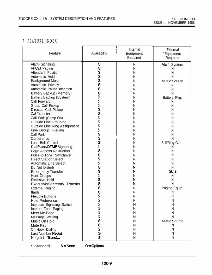
ENCORE CX 8 1 6 SYSTEM DESCRIPTION AND FEATURES SECTION 100ISSUE 2 . NOVEMBER 1988
7 . F E A T U R E I N D E X
Feature
Alarm SignalingAll PagingAttendant PositionAutomatic HoldBackground MusicAutomatic PrivacyAutomatic Pause InsertionBattery Backup (Memory)Battery Backup (System)Call ForwardGroup Call PickupDirected Call Pickup
TransferCall Wait (Camp-On)Outside Line GroupingOutside Line Ring AssignmentLine Group QueuingCall ParkConferenceLoud Bell ControlDial SignalingPage Access RestrictionPulse-to-Tone SwitchoverDirect Station SelectAutomatic Line SelectDo Not DisturbEmergency TransferHunt GroupsExclusive HoldExecutive/Secretary TransferExternal PagingflashFlexible ButtonsHold PreferenceIntercom Signaling SwitchInternal Zone PagingMeet Me PageMessage WaitingMusic On HoldMute KeyOn-Hook DialingLast Number N i g h t
S-Standard
AvailabilityInternal
EquipmentRequired
0SS
SSSS
S
SS
S
SSSSSS
S
NNNNNNNNNNNNNNNNNNNNNNNNN
N
NNNNNNNNNNNNN
ExternalI
Equipment i
Required
SystemNNN
Music SourceNNN
Battery Pkg.NNNNNNNNNN
Bell/Ring Gen .NNNNNN
NNN
Paging Equip.NNNNNNN
Music SourceNNNN

SECTION 100 ENCORE CX 816 SYSTEM DESCRIPTION AND FEATURESISSUE 2 , NOVEMBER 1988
7. FEATURE INDEX
Feature
Preset Call ForwardPBX Dialing CodesRinging Line AnswerPrivate tineSave Number RedialSMDRSpeakerphoneSystem HoldReal Time ClockSystem Speed DialStation Speed DialToll Restriction
MessagesWall Telephone
Internal ExternalAvailability Equipment Equipment
Required Required
S N NS N NS N NS N N
N NSIU + RCU + PM2 Printer
S N NN N
RCU Unit + PM2 LCD PhoneS N NS N N
N NN LCD Phone
S N N
100-l 0
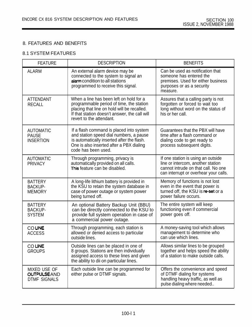
ENCORE CX 816 SYSTEM DESCRIPTION AND FEATURES SECTION 100ISSUE 2, NOVEMBER 1988
8. FEATURES AND BENEFITS
8.1 SYSTEM FEATURES
FEATURE
ALARM
DESCRIPTION
An external alarm device may beconnected to the system to signal an
condition to all stationsprogrammed to receive this signal.
BENEFITS
Can be used as notification thatsomeone has entered thepremises. Used for either businesspurposes or as a securitymeasure.
ATTENDANTRECALL
When a line has been left on hold for aprogrammable period of time, the stationplacing that line on hold will be recalled.If that station doesn’t answer, the call willrevert to the attendant.
Assures that a calling party is notforgotten or forced to wait toolong without word on the status ofhis or her call.
AUTOMATICPAUSEINSERTION
If a flash command is placed into systemand station speed dial numbers, a pauseis automatically inserted after the flash.One is also inserted after a PBX dialingcode has been used.
Guarantees that the PBX will havetime after a flash command ordialing code to get ready toprocess subsequent digits.
AUTOMATICPRIVACY
Through programming, privacy isautomatically provided on all calls.
feature can be disabled.
If one station is using an outsideline or intercom, another stationcannot intrude on that call. No onecan interrupt or overhear your calls.
BATTERYBACKUP-MEMORY
BATTERYBACKUP-SYSTEM
A long-life lithium battery is provided in Memory of functions is not lostthe KSU to retain the system database in even in the event that power iscase of power outage or system power turned off, the KSU is or abeing turned off. power failure occurs.
An optional Battery Backup Unit (BBU) The entire system will keepcan be directly connected to the KSU to functioning even if commercialprovide full system operation in case of power goes off.a commercial power outage.
CO ACCESS
CO GROUPS
Through programming, each station isallowed or denied access to particularoutside lines.
Outside lines can be placed in one of8 groups. Stations are then individuallyassigned access to these lines and giventhe ability to dii on particular lines.
A money-saving tool which allowsmanagement to determine whocan use which lines.
Allows similar lines to be groupedtogether and helps speed the abilityof a station to make outside calls.
MIXED USE OF AND
DTMF SIGNALS
Each outside line can be programmed foreither pulse or DTMF signals.
Offers the convenience and speedof DTMF dialing for systemshandling heavy traffic, as well aspulse dialing where needed..
100-l 1
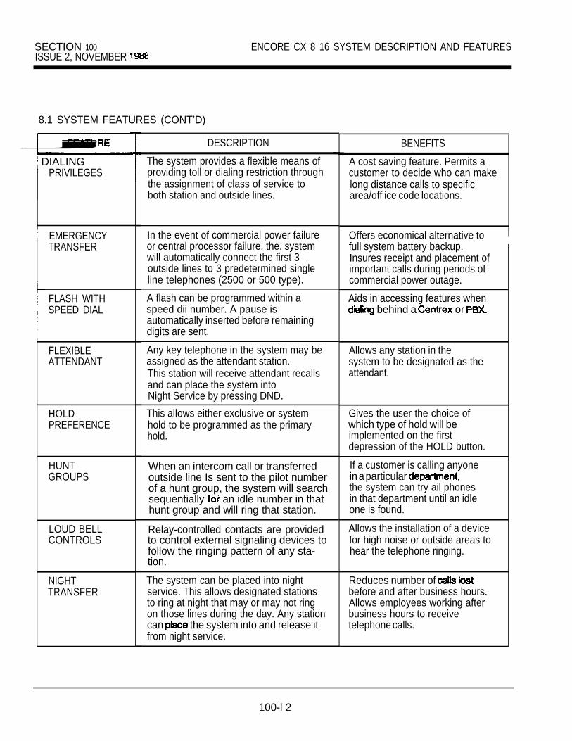
SECTION 100ISSUE 2, NOVEMBER
ENCORE CX 8 16 SYSTEM DESCRIPTION AND FEATURES
8.1 SYSTEM FEATURES (CONT’D)
DIALINGPRIVILEGES
EMERGENCYTRANSFER
FLASH WITHSPEED DIAL
FLEXIBLEATTENDANT
HOLDPREFERENCE
HUNTGROUPS
LOUD BELLCONTROLS
NIGHTTRANSFER
DESCRIPTION
The system provides a flexible means ofproviding toll or dialing restriction throughthe assignment of class of service toboth station and outside lines.
In the event of commercial power failureor central processor failure, the. systemwill automatically connect the first 3outside lines to 3 predetermined singleline telephones (2500 or 500 type).
A flash can be programmed within aspeed dii number. A pause isautomatically inserted before remainingdigits are sent.
Any key telephone in the system may beassigned as the attendant station.This station will receive attendant recallsand can place the system intoNight Service by pressing DND.
This allows either exclusive or systemhold to be programmed as the primaryhold.
When an intercom call or transferredoutside line Is sent to the pilot numberof a hunt group, the system will searchsequentially an idle number in thathunt group and will ring that station.
Relay-controlled contacts are providedto control external signaling devices tofollow the ringing pattern of any sta-tion.
The system can be placed into nightservice. This allows designated stationsto ring at night that may or may not ringon those lines during the day. Any stationcan the system into and release itfrom night service.
BENEFITS
A cost saving feature. Permits acustomer to decide who can makelong distance calls to specificarea/off ice code locations.
Offers economical alternative tofull system battery backup.Insures receipt and placement ofimportant calls during periods ofcommercial power outage.
Aids in accessing features when behind a or
Allows any station in thesystem to be designated as theattendant.
Gives the user the choice ofwhich type of hold will beimplemented on the firstdepression of the HOLD button.
If a customer is calling anyonein a particular the system can try ail phonesin that department until an idleone is found.
Allows the installation of a devicefor high noise or outside areas tohear the telephone ringing.
Reduces number of before and after business hours.Allows employees working afterbusiness hours to receivetelephone calls.
100-l 2

ENCORE CX 816 SYSTEM DESCRIPTION AND FEATURES SECTION 100ISSUE 2, NOVEMBER 1988
8.1 SYSTEM FEATURES (CONT’D)
FEATURE DESCRIPTION BENEFITS
OUTSIDE L INE Outside lines are assigned to ring at Any line can be programmed toRING individual stations by programming. Any ring on any station during the dayASSIGNMENT station may be programmed to ring for any and/or night, both or neither.
outside line(s) during Day or Night Mode.
PAUSETIMER
PBX DIALCODES
PULSE-TO-TONESWITCHOVER
REAL TIMECLOCK
SMDR
When dialing a speed number, a timed Allows the use of a pause inpause in digit sending can be placed in speed dialing for use behind athe number. The length of this pause can PBX, or in accessingbe programmed. special services.
5 one- or two-digit access codes can be Allows PBX users to more exactlyentered into memory. When one of these determine when toll restriction iscodes is dialed, this signals the KSU to be applied and not confuse thethat toll restriction is to apply at the next dialing of extensions beginningdialed digit after the code. If one of these with 1 with long distance calls.codes is not dialed, toll restriction does Allows dialing of PBX extensionsnot apply. 100, 111, 110, etc.
, The system can change the signaling on Allows the use of common carriersan outside line from dial pulse to tone. and other services behind a dial
pulse line.
An optional unit which allows Executive Allows system time and date telephones with LCD to have time and current in the event of a date displayed. power failure.
An external printer or call accounting This is a cost saving feature.device can be installed to provide Allows you to keep track of whichdetails on both incoming and outgoing stations are making and receivingcalls. (optional) calls as well as the telephone
numbers of the locations beingcalled. Also records duration of .calls.
SYSTEM SPEEDDIAL
Up to 80 commonly numbers can Increases productivity bybe programmed into system speed eliminating time wasted on lookingfor use by stations allowed this feature. up and dialing frequently calledThe 40 numbers not be numbers common to the entiremonitored by toll restriction. system.
100-13

SECTION 100 ENCORE 816 SYSTEM DESCRIPTION AND FEATURESISSUE 2. NOVEMBER
STATION FEATURES
FEATURE
ADD ONCONFERENCE
ALERT TONE
AUTOMATICSELECTION
BUSY STATUSON DSSBUT-TONS
CALLANNOUNCEPRIVACY
CALL PARK
CALLTRANSFER
CALL
DIRECTSTATIONSELECT
DESCRIPTION
Permits you to establish a conference with 2 other internal stations.
Provides an audible signal to the calledparty that a voice call or page willimmediately follow.
The user can select an outside line, anintercom station or speed dial bin andautomatically place the telephone in thedialing mode without lifting the handset orpressing the MONITOR button.
Allows a station to determine at a glanceif the person they wish to call is busyor not.
Each telephone user can set the intercomsignal switch to receive one-wayintercom call announcements thehandset must be lifted or signal switchmoved to HF to respond.
You can place an outside line in one of 6parking locations and it can be retrievedby any station in the system.
An outside call can be transferred fromone station to another within the system.The transferred call will ring at thereceiving station even though it is notnormally programmed to do so.
A station user may alert a busy party thatan outside line is on hold and waiting forthem.
The user with DSS buttons assigned athis or her key telephone can call intercom station by simply pressing theappropriate DSS button. The calledstation is automatically signaled.
BENEFITS
Saves time and ensuresinformation is received andunderstood.
Notifies a station that an intercomvoice call or a page call will followimmediately.
Simplifies the making of calls byhaving the user press only onekey to access an outside line,an intercom station or speed dialbin.
Saves time and prevents busysignal irritation.
You can receive callannouncements but not allow thecalling party to hear privateconversations in progress.
Call park has a separate timerwhich allows these calls to beplaced on hold longer and then beretrieved at any station.
Expedites efficient call handling.
Allows a busy user to be notifiedof and handle a 2nd caller and stillprovide professional courteous
to both
Allows rapid handling of calls.

ENCORE CX 816 SYSTEM DESCRIPTION AND FEATURES SECTION 100ISSUE 2. NOVEMBER 1988
8.2 STATION FEATURES
FEATURE
DIRECTEDCALL PICKUP
DISPLAYCAPABILITIES
DESCRIPTION BENEFITS
A station can pick up an intercom or Enables quick response by anotheroutside line call ringing on a station to calls that mightunattended station. otherwise be unanswered.
Visual indication of call status is provided. Allows stations equipped with theCalls to and from other extensions, LCD feature to receive specialnumber dialed, line used and call waiting messages, call status indication,are among the features displayed. and the convenient date andThe LCD also displays time, date and time display.other call processing information. (optional)
DO NOTDISTURB
EXCLUSIVEHOLD
EXECUTIVE/SECRETARYTRANSFER
KEY
FLEXIBLEBUTTONASSIGNMENT
Eliminates incoming outside line ringing, Ensures your business meeting orintercom calls, transfers and paging other activity will not be interruptedannouncements. by a phone call.
When a line is placed on exclusive hold, Ensures that no one else canno other station in the system can pick up a call you placed on hold,retrieve the call. so you won’t lose the call.
Executives can have an assigned Allows busy executives to havesecretary station(s) receive intercom their calls automatically transferredcalls and transfers when they are busy to designated or in DND. to take messages.
Provides you with the ability to terminate Allows you to terminate a call on anan outside call and restore dial tone outside line without losing that linewithout hanging up the phone. so another call can be placed.
Each key telephone user can have Allows each user to customizeindividually programmed buttons. his/her own phone based on6 operations are possible: outside line, individual needs and calling
feature key, speed dii, loop, patterns.
GROUP CALLPICKUP
HANDSFREEANSWERBACK
Stations can be placed in one or more of4 pickup groups. Stations in the samegroup can pick up tone ringing intercomor transferred calls for another station.
Each telephone user can set intercomsignal switch to receive call ments and respond handsfree bysimply speaking in a normal tone of voice.
Enables you to answer a call to anyunattended station from your ownphone without knowing the extensionnumber of the ringing phone.
Frees your hands to do other while talking on the
telephone.
HOLD RECALL When an outside call has been on hold Assures that a caller is neither.for a programmable length of time, a forgotten nor made to wait on holdrecall tone is sent to the originating too long without a response.station. If unanswered by this station, Improves your company’s imagethe attendant is recalled. to customers.
100-l 5
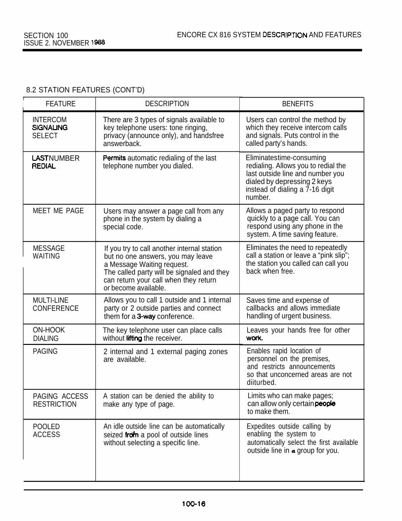
SECTION 100 ENCORE CX 816 SYSTEM AND FEATURESISSUE 2. NOVEMBER
8.2 STATION FEATURES (CONT’D)rI FEATURE
INTERCOM
SELECT
NUMBER
MEET ME PAGE
MESSAGEWAITING
MULTI-LINECONFERENCE
ON-HOOKDIALING
PAGING
PAGING ACCESS A station can be denied the ability toRESTRICTION make any type of page.
POOLEDACCESS
DESCRIPTION
There are 3 types of signals available tokey telephone users: tone ringing,privacy (announce only), and handsfreeanswerback.
automatic redialing of the lasttelephone number you dialed.
Users may answer a page call from anyphone in the system by dialing aspecial code.
If you try to call another internal stationbut no one answers, you may leavea Message Waiting request.The called party will be signaled and theycan return your call when they returnor become available.
Allows you to call 1 outside and 1 internal Saves time and expense ofparty or 2 outside parties and connect callbacks and allows immediatethem for a conference. handling of urgent business.
The key telephone user can place callswithout the receiver.
2 internal and 1 external paging zonesare available.
An idle outside line can be automaticallyseized a pool of outside lineswithout selecting a specific line.
BENEFITS
Users can control the method bywhich they receive intercom callsand signals. Puts control in thecalled party’s hands.
Eliminates time-consumingredialing. Allows you to redial thelast outside line and number youdialed by depressing 2 keysinstead of dialing a 7-16 digitnumber.
Allows a paged party to respondquickly to a page call. You canrespond using any phone in thesystem. A time saving feature.
Eliminates the need to repeatedlycall a station or leave a “pink slip”;the station you called can call youback when free.
Leaves your hands free for other
Enables rapid location ofpersonnel on the premises,and restricts announcementsso that unconcerned areas are notdiiturbed.
Limits who can make pages;can allow only certain to make them.
Expedites outside calling byenabling the system toautomatically select the first availableoutside line in group for you.

ENCORE CX 816 SYSTEM DESCRIPTION AND FEATURES SECTION 100ISSUE 2. NOVEMBER 1988
8.2 STATION FEATURES (CONT’D)
FEATURE
PRESELECTEDMESSAGES
PRESET CALLFORWARD
QUEUING
RINGING
PREFERENCE
SAVE NUMBER
STATION CALLFORWARD
STATIONSPEED DIAL
SPEAKERPHONE
SYSTEM HOLD
VOLUMECONTROL
DESCRIPTION
If you are going to be out of your office,you can leave one of 10 specialmessages to be displayed on internalcallers’ LCD phones.
Incoming outside lines which areprogrammed to ring at a particular stationcan be programmed to forward toanother station if the first stationdoesn’t answer.
Allows you to wait for a particular outsideline group that is busy to become free.Your phone will ring as soon as a line inthe desired line group is available.
Allows a station to answer any assignedringing outside line by simply lifting thehandset or pressing the MONITORbutton.
Allows you to save an outside numberyou just dialed and have had difficultyreaching. This number can be atyour request even if you make other in between.
Enables you to forward all intercom andCO calls to another station.
You can store 20 frequently dialedpersonal numbers in the telephone’smemory. At your request, the desirednumber will be automatically dialed.
Each key telephone is equipped with aspeakerphone which can be programmedto work in one of 3 ways: normal,handsfree only, headset only.
When a line Is placed on system hold,any station that has a direct line ap-pearance can retrieve the call.
Permits you to control the level of tonesand voice announcements heard throughbuilt-in speaker.
BENEFITS
A l l o w s you to notify callers (withLCD displays) of yourwhereabouts.
Allows for a backup attendant ifthe original attendant is busy orhas to leave her station. Helpsprevent unanswered calls andannoyed callers.
Enables a station user to proceedwith other work while waiting for abusy outside line to become availableHelps maximize use of available lines.
Provides one-step operation byallowing the user to answer thetelephones without manuallyselecting the ringing line.
Increases productivity byeliminating time wasted on digit
Reduces the number of lost calls,lost messages and callbacks.
Increases productivity byeliminating time wasted on digit dialing of frequently numbers.
Frees your hands for other workwhile talking on the telephone.Allows 2 or more people in one
to speak on the speaker-phone to an outside party.
Allows a line to be put on hold atone station and be picked up atanother station where it appears.
you to choose a comfortablevolume level. This level can bec h a n g e d as desired. I
1 0 0 - l 7

SECTION 100 ENCORE 816 SYSTEM DESCRIPTION AND FEATURES
9. PROGRAM MODULE 3
Program Module 3 (PM-3) software provides anumber of new features for the ENCORE CX 816 sys-tem. The features described on the following pagesare also available in Feature Package V software forENCORE CX 3672 and 36112 systems.
10. PM-3: STATION FEATURES
The following features are available to key telephonestation users.
10.1 AUTOMATIC RELEASE OF THE MONITORBUTTON
The MONITOR button will turn off automatically afterthe completion of the following features: call park,callback, call forward, queuing and pre-selected mes-sages. The phone returns to the on-hook condition.This feature functions only if the MONITOR key wasused to activate the feature in question.
10.2 AUTOMATIC
Allows you to save an outside number you have haddifficulty reaching (busy or no answer). The systemwill ring your phone after a programmed time and will the number for you automatically. TheAutomatic feature uses the Number
bin.
The system-wide Auto timer is program-mable from seconds, and default is seconds. When the timer and the systemcalls back your phone, your phone for seconds and then cancel, if The featurewill also cancel if you seize a CO line or on theoriginal CO line, or if you forward your calls or putyour phone in DND. If you are busy when the timerexpires, the timer resets and starts again.
You must have a direct appearance the CO line, ora loop or pool key, for this feature to be
10.3 CALL FORWARD BUSY/NO ANSWER
Permits a station user to forward busy calls, noanswer calls, or a combination busy/no answer callsto a designated station or a hunt group pilot number.No answer calls forward when the system-wide “noanswer expires. Intercom calls to answer’stations will forward only when the station Is in tonemode. An Initially ringing CO call cannot forward to a
unless the has a direct line appearancefor that call. Initially ringing CO calls cannot be for-warded to a hunt group.
10.4 CANNED TOLL EXPANDED
Canned toll restriction has been expanded to allowaccess to certain toll free calls and to deny access tocertain other calls. The expanded canned toll restric-tion Is applied to all stations with COS 5. Theseentries supplement the existing COS 5 tables.
976411
l-911 5551811
10.5 DIAL MEMO
You can a telephone number into your phone’smemory as a reminder to yourself to call that number.This can be done you are using the phone,
interrupting the call in progress. When yourcall in progress completed, you can prompt the
to the number you stored. feature the Save/Repeat bin, any
previously stored Save/Repeat number in the bin willbe erased when the Memo feature is used.
10.6 FLASH ON INTERCOM CALLS
The user can terminate calls andpages by the FLASH key of hanging up.
tone is returned and another call can be madeImmediately. This feature provides a better way of ter-minating page announcements.

ENCORE CX 8 1 6 SYSTEM DESCRIPTION AND FEATURES SECTION ISSUE 2. NOVEMBER 1988
10.7 INTERCOM CALL HOLD
You can program a flexible button to allow an inter-com call to be put on hold. Only one flexible buttonmay be programmed at each station for intercomhold. In addition, only one intercom may be puton hold at one time.
10.8 ONE-TIME DO NOT DISTURB (DND)
Allows you to prevent calls from ringing at your stationwhile you’re on a call. Useful when you’re having animportant conversation and do not wish to be dis-turbed by ringing. The One-Time DND condition willautomatically cancel when you end your call. Thisfeature is not available to Intercom Phone Box users.
10.9 PROGRAMMING CODE 72 ON A FLEX KEY
You can program code 72 on a flexible key. Thisspeeds access of pre-selected messages. In earliersoftware versions you could only program a specificmessage on a flex key. Now you can program the 72code on a flex key and then dial the code for anydesired pre-selected message.
10.10 PROGRESS TONES ON HANDSFREEANSWERBACK
In handsfree answerback mode (speakerphone type2) a user can hear a CO party but must the handsetto be heard. Wlth earlier software no progress tonesare heard when you make an intercom or areprogramming; nor do you hear intercom dial tone you go off-hook by pressing the monitor button.Program Module 3 software tones toallow you to your
10.11 RECALL RING
Recall ring tone has been changed. ‘In earlier soft-ware, recall ringing was the same as a new incomingCO call. The change the user to
discern a recalling CO call from a new incoming COcall. The following features are impacted by thischange: call park, system hold, exclusive hold, trans-fer recall. Recall ring tone is now the same as COQueue Callback ring tone.
11. PM-3: ATTENDANT FEATURES
11 OUTGOING ACCESS
The attendant station can disable CO lines, preventingoutgoing CO calls. Useful for removing a faulty linefrom service, or for CO lines for importantuse. All stations that can normally make calls on thelines are affected, but incoming calls are not affected.A CO line may be disabled while is being used;when the trunk becomes idle, further outgoing accesswill be prevented.
11.2 SELECTING BACKGROUND MUSIC AT ANINTERCOM PHONE BOX FROM THEATTENDANT STATION
The attendant station can turn on background musicat an intercom phone box station. In eatiler softwareversions this could be accomplished only throughadmin programming.
12. PM-3: INTERCOM PHONE BOXFEATURES
12.1 BLOCKING BACKGROUND MUSIC
An Intercom box station can block backgroundmusic using the Do Not Disturb @ND) button. This istrue regardless of whether or not DND allowed at

SECTION 100 ENCORE CX 816 SYSTEM DESCRIPTION AND FEATURESISSUE 3. NOVEMBER 1989
13. PROGRAM MODULE 15.2 ADDITIONAL PROGRAMMING CODESSOFTWARE
Program Module (PM-3-ENH) softwareprovides new features for the ENCORE CX 408816system. These new features described on the ing pages are included with the features provided bythe Program Module 3 software.
14. SYSTEM FEATURES
The following system feature is available with thissoftware.
14.1 ENHANCED KEY TELEPHONECOMPATIBILITY
Provides software control which special fea-ture operations necessary for the use of theENCORE CX Enhanced Key Telephone.
The following feature functions can he programmedon a flexible feature button using the assignedprogramming code. These codes are intended foruse by the user of the Enhanced KeyTelephone where a fixed feature or does not exist.
Monitor 696693
Call Back 692690
Conference 691Flash 694Mute 695Ring Code 699
15.3 TRANSFER SEARCH WITH RECOVERY
The existing transfer feature has been improved toallow the search for a station user with ofthe call the transfer cannot be completed. This fea-ture can also he used with the new Abbreviated Con-ference feature.
STATION FEATURES.
following features are available to keytelephone station users when using this software.
15.1 ADDITIONAL DIAL CODES
The features below can be initiated using the signed dial codes giving the user an alternate way touse the feature without having or programmedfeature buttons for the fixed features.
15.4 ABBREVIATED CONFERENCE
the fixed on any keytelephone to be used to establish an add-on ference. The outside call must be made first. TheTransfer Search Recovery feature can also beused in conjunction with this feature albwing easyconference or supervised call set up. Exiting the ferenca in progress permitted but does not albw entry.
DIAL CODES
Flash on CO line 5153
Call Forward 54 DestinationProgram Speed Dial Bins 55 Bin NumberPlace Message Wait/Callback 56Return Message 57Cancel Call Forward DND 59Dial Speed Dial Bins + Bin NumberProgram Flexible Buttons + Flex Btn + CodeIntercom Ring Control 699

ENCORE CX 3672 SECTION 101KEY TELEPHONE SYSTEM ISSUE 2. NOVEMBER 1988
ENCORE CX 3672 SYSTEM DESCRIPTION AND FEATURES
TABLE OF CONTENTS
1. SYSTEM DESCRIPTION . . . . . . . . . . . . . . . . . . . . . . . . . . . . . . . . . . . . . . . . . . . . . . . . . . . . . .
2. EQUIPMENT DESCRIPTION2.1 BASIC KEY SERVICE UNIT (KSU) . . . . . . . . . . . . . . . . . . . . . . . . . . . . . . . . . . . . . . . . .2.2 ENHANCED PROCESSOR BOARD (EPB) . . . . . . . . . . . . . . . . . . . . . . . . . . . . . . . . . .2.3 CENTRAL OFFICE INTERFACE BOARD (COB) . . . . . . . . . . . . . . . . . . . . . . . . . . . . . .2.4 KEY TELEPHONE INTERFACE BOARD . . . . . . . . . . . . . . . . . . . . . . . . . . . . . . .2.5 POWERSUPPLY . . . . . . . . . . . . . . . . . . . . . . . . . . . . . . . . . . . . . . . . . . . . . . . . . . . . . . . .2.6 . . . . . . . . . . . . . . . . . . . . . . . . . . . . . . . . . . . . . . . . . . . . . . . . . . . . .
3. OPTIONAL EQUIPMENT3.1 EXPANSION KSU . . . . . . . . . . . . . . . . . . . . . . . . . . . . . . . . . . . . . . . . . . . . . . . . . . . . . .
3.2 ADDITIONAL PORT FOR SMDR . . . . . . . . . . . . . . . . . . . . . . . . . . . . . . . . . . .
3.3 DC/DC CONVERTER WITH BATTERY CHARGING BOARD . . . . . . . . . . . . . . . . . . . .
3.4 EMERGENCY TRANSFER MODULE . . . . . . . . . . . . . . . . . . . . . . . . . . . . . . . . .
3.5 BOARD (APL) . . . . . . . . . . . . . . . . . . . . . . . . . . . . . . . . . . . . . . . . . . . . .3.6 SINGLE UNE RING GENERATOR AND POWER SUPPLY (RGU) . . . . . . . . . . .3.7 OFF-HOOK VOICE ANNOUNCE BOARD (KIBOH) . . . . . . . . . . . . . . . . . . . . . . . . . . .3.8 SINGLE LINE INTERFACE BOARD (SIB) . . . . . . . . . . . . . . . . . . . . . . . . . . . . . . . . . . .3.9 RECEIVER/SENDER MODULE (RSM) . . . . . . . . . . . . . . . . . . . . . . . . . . . . . . . . . . . . .3.10 DIRECT STATION SELECT (DSS) CONSOLE . . . . . . . . . . . . . . . . . . . . . . . . . . . . . . .3.11 AMPLIFIED CENTRAL OFFICE BOARD . . . . . . . . . . . . . . . . . . . . . . . . . . . . . . . . . . . .3.12 ENCORE CX 3672 SOFTWARE . . . . . . . . . . . . . . . . . . . . . . . . . . . . . . . . . . . . . . . . . . .3.13 ENCORE CX 3672 SOFTWARE WITH LCR . . . . . . . . . . . . . . . . . . . . . . . . . . . . . . . . . .3.14 SINGLE LINE OPX BOARD . . . . . . . . . . . . . . . . . . . . . . . . . . . . . . . . . . . . . . . . . . . . . .
4. FEATURE INDEX . . . . . . . . . . . . . . . . . . . . . . . . . . . . . . . . . . . . . . . . . . . . . . ...*... . . . . . . . .
5. ADDITIONAL 3672 FEATURES5.1 ADD ON CONFERENCE . . . . . . . . . . . . . . . . . . . . . . . . . . . . . . . . . . . . . . . . . . . . . . . . . 65.2 OVERRIDE . . . . . . . . . . . . . . . . . . . . . . . . . . . . . . . . . . . . . . . . . . . . . . . . . 65.3 (DIRECT INWARD SYSTEM ACCESS) . . . . . . . . . . . . . . . . . . . . . . . . . . . . . . . .5.4 LEAST COST . . . . . . . . . . . . . . . . . . . . . . . . . . . . . . . . . . . . . . . . . . . . . . . . .
5.5 MULTI-LINE CONFERENCE . . . . . . . . . . . . . . . . . . . . . . . . . . . . . . . . . . . . . . . . . . . . .5.6 OFF-HOOK VOICE ANNOUNCE . . . . . . . . . . . . . . . . . . . . . . . . . . . . . . . . . . . . . . . . . .5.7 PAGING . . . . . . . . . . . . . . . . . . . . . . . . . . . . . . . . . . . . . . . . . . . . . . . . . . . . . . . . . . . . .5.8 TIME AND DATE PROGRAMMING . . . . . . . . . . . . . . . . . . . . . . . . . . . . . . . . . . . . . . . .5.9 UNSUPERVISED CONFERENCE . . . . . . . . . . . . . . . . . . . . . . . . . . . . . . . . . . . . . . . . .
101-A
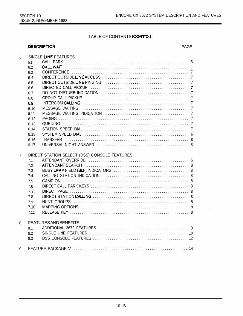
SECTION 101 ENCORE CX 3672 SYSTEM DESCRIPTION AND FEATURESISSUE 2, NOVEMBER 1988
TABLE OF CONTENTS
6. SINGLE FEATURES
PAGE
6.1 CALL PARK . . . . . . . . . . . . . . . . . . . . . . . . . . . . . . . . . . . . . . . . . . . . . . . . . . . . . . . . . . . 66.2 . . . . . . . . . . . . . . . . . . . . . . . . . . . . . . . . . . . . . . . . . . . . . . . . . . . . . . . . . . . .6.3 CONFERENCE . . . . . . . . . . . . . . . . . . . . . . . . . . . . . . . . . . . . . . . . . . . . . . . . . . . . . . . . 76.4 DIRECT OUTSIDE ACCESS . . . . . . . . . . . . . . . . . . . . . . . . . . . . . . . . . . . . . . . . . 76.5 DIRECT OUTSIDE RINGING . . . . . . . . . . . . . . . . . . . . . . . . . . . . . . . . . . . . . . . . . 76.6 DIRECTED CALL PICKUP . . . . . . . . . . . . . . . . . . . . . . . . . . . . . . . . . . . . . . . . . . . . . . .6.7 DO NOT DISTURB INDICATION . . . . . . . . . . . . . . . . . . . . . . . . . . . . . . . . . . . . . . . . . . 76.8 GROUP CALL PICKUP . . . . . . . . . . . . . . . . . . . . . . . . . . . . . . . . . . . . . . . . . . . . . . . . . . 7
INTERCOM . . . . . . . . . . . . . . . . . . . . . . . . . . . . . . . . . . . . . . . . . . . . . . . . . . . 76.10 MESSAGE WAITING . . . . . . . . . . . . . . . . . . . . . . . . . . . . . . . . . . . . . . . . . . . . . . . . . . . . 76.11 MESSAGE WAITING INDICATION . . . . . . . . . . . . . . . . . . . . . . . . . . . . . . . . . . . . . . . . . 76.12 PAGING . . . . . . . . . . . . . . . . . . . . . . . . . . . . . . . . . . . . . . . . . . . . . . . . . . . . . . . . . . . . . . 76.13 QUEUING . . . . . . . . . . . . . . . . . . . . . . . . . . . . . . . . . . . . . . . . . . . . . . . . . . . . . . . . . . . . 76.14 STATION SPEED DIAL . . . . . . . . . . . . . . . . . . . . . . . . . . . . . . . . . . . . . . . . . . . . . . . . . . 76.15 SYSTEM SPEED DIAL . . . . . . . . . . . . . . . . . . . . . . . . . . . . . . . . . . . . . . . . . . . . . . . . . . 66.16 TRANSFER . . . . . . . . . . . . . . . . . . . . . . . . . . . . . . . . . . . . . . . . . . . . . . . . . . . . . . . . . . . 86.17 UNIVERSAL NIGHT ANSWER . . . . . . . . . . . . . . . . . . . . . . . . . . . . . . . . . . . . . . . . . . . . 8
7. DIRECT STATION SELECT (DSS) CONSOLE FEATURES7.1 ATTENDANT OVERRIDE . . . . . . . . . . . . . . . . . . . . . . . . . . . . . . . . . . . . . . . . . . . . . . . . 67.2 SEARCH . . . . . . . . . . . . . . . . . . . . . . . . . . . . . . . . . . . . . . . . . . . . . . . . . . 87.3 BUSY FIELD INDICATORS . . . . . . . . . . . . . . . . . . . . . . . . . . . . . . . . . . . . 87.4 CALLING STATION INDICATION . . . . . . . . . . . . . . . . . . . . . . . . . . . . . . . . . . . . . . . . . . 87.5 CAMP-ON . . . . . . . . . . . . . . . . . . . . . . . . . . . . . . . . . . . . . . . . . . . . . . . . . . . . . . . . . . . . 87.6 DIRECT CALL PARK KEYS . . . . . . . . . . . . . . . . . . . . . . . . . . . . . . . . . . . . . . . . . . . . . . . 87.7, DIRECT PAGE . . . . . . . . . . . . . . . . . . . . . . . . . . . . . . . . . . . . . . . . . . . . . . . . . . . . . . . . . 87.8 DIRECT STATION . . . . . . . . . . . . . . . . . . . . . . . . . . . . . . . . . . . . . . . . . . . . . . 87.9 HUNT GROUPS . . . . . . . . . . . . . . . . . . . . . . . . . . . . . . . . . . . . . . . . . . . . . . . . . . . . . . . 87.10 MAPPING OPTIONS .. . . . . . . . . . . . . . . . . . . . . . . . . . . . . . . . . . . . . . . . . . . . . . . . . . . . 87.11 RELEASE KEY . . . . . . . . . . . . . . . . . . . . . . . . . . . . . . . . . . . . . . . . . . . . . . . . . . . . . . . . . 8
6. FEATURES AND BENEFITS8.1 ADDITIONAL 3672 FEATURES . . . . . . . . . . . . . . . . . . . . . . . . . . . . . . . . . . . . . . . . . . . 98.2 SINGLE UNE FEATURES . . . . . . . . . . . . . . . . . . . . . . . . . . . . . . . . . . . . . . . . . . . . . . . 108.3 DSS CONSOLE FEATURES . . . . . . . . . . . . . . . . . . . . . . . . . . . . . . . . . . . . . . . . . . . . . 12
9. FEATURE PACKAGE V . . . . . . . . . . . . . . . . . . . . . . . . . . . . . . . . . . . . . . . . . . . . . . . . . . . . . 14
101-B
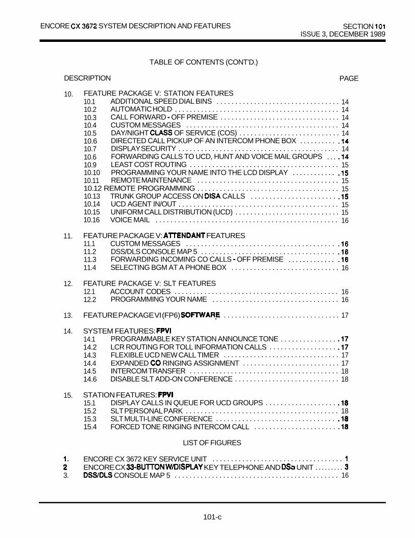
ENCORE SYSTEM DESCRIPTION AND FEATURES SECTION ISSUE 3, DECEMBER 1989
TABLE OF CONTENTS (CONT’D.)
DESCRIPTION PAGE
10. FEATURE PACKAGE V: STATION FEATURES10.1 ADDITIONAL SPEED DIAL BINS . . . . . . . . . . . . . . . . . . . . . . . . . . . . . . . . . 1410.2 AUTOMATIC HOLD . . . . . . . . . . . . . . . . . . . . . . . . . . . . . . . . . . . . . . . . . . . . 1410.3 CALL FORWARD OFF PREMISE . . . . . . . . . . . . . . . . . . . . . . . . . . . . . . . . 1410.4 CUSTOM MESSAGES . . . . . . . . . . . . . . . . . . . . . . . . . . . . . . . . . . . . . . . . . 1410.5 DAY/NIGHT OF SERVICE (COS) . . . . . . . . . . . . . . . . . . . . . . . . . . . 1410.6 DIRECTED CALL PICKUP OF AN INTERCOM PHONE BOX . . . . . . . . . .10.7 DISPLAY SECURITY . . . . . . . . . . . . . . . . . . . . . . . . . . . . . . . . . . . . . . . . . . . 1410.6 FORWARDING CALLS TO UCD, HUNT AND VOICE MAIL GROUPS . . .10.9 LEAST COST ROUTING . . . . . . . . . . . . . . . . . . . . . . . . . . . . . . . . . . . . . . . . 1510.10 PROGRAMMING YOUR NAME INTO THE LCD DISPLAY . . . . . . . . . . . .10.11 REMOTE MAINTENANCE . . . . . . . . . . . . . . . . . . . . . . . . . . . . . . . . . . . . . . 1510.12 REMOTE PROGRAMMING . . . . . . . . . . . . . . . . . . . . . . . . . . . . . . . . . . . . . . 1510.13 TRUNK GROUP ACCESS ON CALLS . . . . . . . . . . . . . . . . . . . . . . .10.14 UCD AGENT IN/OUT . . . . . . . . . . . . . . . . . . . . . . . . . . . . . . . . . . . . . . . . . . . 1510.15 UNIFORM CALL DISTRIBUTION (UCD) . . . . . . . . . . . . . . . . . . . . . . . . . . . . 1510.16 VOICE MAIL . . . . . . . . . . . . . . . . . . . . . . . . . . . . . . . . . . . . . . . . . . . . . . . . . 16
11. FEATURE PACKAGE V: FEATURES11.1 CUSTOM MESSAGES . . . . . . . . . . . . . . . . . . . . . . . . . . . . . . . . . . . . . . . .11.2 DSS/DLS CONSOLE MAP 5 . . . . . . . . . . . . . . . . . . . . . . . . . . . . . . . . . . . .11.3 FORWARDING INCOMING CO CALLS OFF PREMISE . . . . . . . . . . . . .11.4 SELECTING BGM AT A PHONE BOX . . . . . . . . . . . . . . . . . . . . . . . . . . . . . 16
12. FEATURE PACKAGE V: SLT FEATURES12.1 ACCOUNT CODES . . . . . . . . . . . . . . . . . . . . . . . . . . . . . . . . . . . . . . . . . . . . 1612.2 PROGRAMMING YOUR NAME . . . . . . . . . . . . . . . . . . . . . . . . . . . . . . . . . . 16
13. FEATURE PACKAGE VI (FP6) . . . . . . . . . . . . . . . . . . . . . . . . . . . . . . . 17
14. SYSTEM FEATURES: 14.1 PROGRAMMABLE KEY STATION ANNOUNCE TONE . . . . . . . . . . . . . . .14.2 LCR ROUTING FOR TOLL INFORMATION CALLS . . . . . . . . . . . . . . . . . .14.3 FLEXIBLE UCD NEW CALL TIMER . . . . . . . . . . . . . . . . . . . . . . . . . . . . . . . 1714.4 EXPANDED RINGING ASSIGNMENT . . . . . . . . . . . . . . . . . . . . . . . . . . 1714.5 INTERCOM TRANSFER . . . . . . . . . . . . . . . . . . . . . . . . . . . . . . . . . . . . . . . . 1814.6 DISABLE SLT ADD-ON CONFERENCE . . . . . . . . . . . . . . . . . . . . . . . . . . . . 18
15. STATION FEATURES: 15.1 DISPLAY CALLS IN QUEUE FOR UCD GROUPS . . . . . . . . . . . . . . . . . . .15.2 SLT PERSONAL PARK . . . . . . . . . . . . . . . . . . . . . . . . . . . . . . . . . . . . . . . . . 1815.3 SLT MULTI-LINE CONFERENCE . . . . . . . . . . . . . . . . . . . . . . . . . . . . . . . .15.4 FORCED TONE RINGING INTERCOM CALL . . . . . . . . . . . . . . . . . . . . . .
LIST OF FIGURES
ENCORE CX 3672 KEY SERVICE UNIT . . . . . . . . . . . . . . . . . . . . . . . . . . . . . . . . . . .ENCORE CX KEY TELEPHONE AND UNIT . . . . . . . . .
3. CONSOLE MAP 5 . . . . . . . . . . . . . . . . . . . . . . . . . . . . . . . . . . . . . . . . . . . . 16
101-c

ENCORE CX 3672 SECTION KEY TELEPHONE SYSTEM ISSUE 2. NOVEMBER 1988
ENCORE CX 3672 SYSTEM DESCRIPTION AND FEATURES
1. SYSTEM DESCRIPTION
The ENCORE CX 3672 key telephone system isdesigned for the medium size business market wltha maximum.of 36 outside lines and 72 internaltelephone stations. The 3672 is a modular, expan-dable system with all of the same features as thesmaller ENCORE CX 816 system. (Alarm is not in-cluded in this system). In addition, the 3672 systemprovides a number of additional features, includingDISA, off-hook voice announce, unsupervised to-trunk conference, and capability.
Standard 2500 Single Line Telephones can beinstalled by exchanging key station interface boardswith single line interface boards, allowing 8 toreplace 8 for each board exchanged. can access most system features, including callpickup, transfer, call park, intercom calling, paging,speed dial, message waiting, call waiting, do not dis-turb, direct outside line ringing, call forward, andqueuing.
Customers who are upgrading from the smallerENCORE CX system will find that their existingENCORE CX phones can be used in the 3672system.
A Direct Station/Line Selector console is availableand can be programmed in 5 different ways for dif-ferent combinations of stations and trunks. The DSSconsole also includes such fixed feature buttons aspaging, call park, hunt groups, override and callwait. Up to 3 DSS units can be assigned to a stationand there is no limit to the number of DSS units inthe system other than that each DSS unit uses a keytelephone
FIGURE 1. ENCORE CX 3672 KEY SERVICE UNIT
1 0 1 - l

SECTION 101 ENCORE CX 3672 SYSTEM DESCRIPTION AND FEATURES
2. EQUIPMENT DESCRIPTION
A basic system (required for system operation) mustinclude the following:
Basic KSUEnhanced Processor Board (EPB)Key Telephone Interface Board Power Supply (24 volt)DC/DC Converter
Optional boards will be discussed later.
2.1 BASIC KEY SERVICE UNIT (KSU)
The Basic KSU is housed in a wall-mount cabinetthat contains card slots for modular boards andassociated pre-wired connectors. The KSU providescard slot positions for 18 CO/PBX lines, 32 stations,DC/DC converter, Application module and one Emer-gency Transfer module.
2.2 ENHANCED PROCESSOR BOARD (EPB)
This board provides the system’s main 16 bit micro-processor and operating memory. It controls ailsystem activii including switching functions andfeature operation. This board houses the Program-mable Read Only Memory (PROM) genericoperating instructions, and Random Access Memory(RAM) for customer data base programming. Alithium battery is included for protection of the RAMmemory. An RS-232C connector for data printout, Remote Programming/Maintenance andSMDR is included.
The Enhanced Processor Board (EPB) is shippedwithout software. The capabilities of the board arecontrolled by the software package installed on it.Refer to Optional Equipment paragraph for availablesoftware packages. The EPB replaces obsoleteCentral Processor Board (CPB).
2.3 CENTRAL OFFICE INTERFACE BOARD (COB)
Interfaces 6 loop start CO/PBX lines and provides forboth dial pulse and DTMF signaling. Includes MOVprotection circuitry. The board can be removed orinserted with KSU power ON. An in-use LED foreach circuit and a switch to take the board out ofservice for maintenance are provided.
2.4 KEY TELEPHONE INTERFACE BOARD (KIB)
Provides interface circuitry for eight electronic keytelephones. The board will support ail of the CX keytelephone sets. Does not include the capability foroff-hook voice announce. The board can be insertedor removed the KSU power ON. An LED (toindicate in-use status) and a switch (to take the cardout of are provided. A DSS or Phone Boxcan be assigned to any one of the circuits.
2.5 POWER SUPPLY
The power supply unit provides the 24 volt powerneeded for system operation. One power required for the Basic KSU and one additional powersupply is required for the Expansion KSU. Both unitsplug into the Basic KSU.
2.6 DC/DC CONVERTER
A modular unit that converts the 24 VDC power into VDC and 14 VDC system operating voltages. .The
unit also provides LED voltage indicators, test pointsand adjustments, as well as input jacks for MOH sources with level adjustments.
101-2

ENCORE SYSTEM DESCRIPTION AND FEATURES SECTION ISSUE 2. NOVEMBER
FIGURE 2. ENCORE CX WITH DISPLAYKEY TELEPHONE AND UNIT

SECTION 101 ENCORE CX 3672 SYSTEM DESCRIPTION AND FEATURES
3. OPTIONAL EQUIPMENT
3.1 EXPANSION KEY SERVICE UNIT
The Expansion KSU is housed in a wall mount cabinetand contains card slots for 18 lines, stations and emergency transfer module. power supplies must be installed in the Basic KSU.
3.2 ADDITIONAL PORT FOR SMDR
This module mounts on the Application Board andprovides a second connector. This tor may be used to output SMDR data while thestandard is used for system printout.
3.3 DC/DC CONVERTER WITH BATTERYCHARGING BOARD (BCB)
May be installed instead of the standard DC/DC con-verter and provides constant voltage charging forexternal GEL-TYPE batteries. During commercialpower failure, full system operation is maintainedwithout dropping connected calls. monitorsbattery discharge during a commercial power outageto prevent battery damage due to Atone emitting unit will sound an audible alerttone to warn the customer that their system is runningon stand-by power and to restore commercial powerbefore the batteries are discharged and the system isout of service.
3.4 EMERGENCY TRANSFER MODULE
Provides automatic direct cut-through of 6CO/PBX lines to 6 In ofcommercial power failure. The single line may may not beintercom stations. If they are not Intercom stationsthen the 3672 system does not require any equipment. There can be 2 units: one into theBasic KSU and one plugs into the Expansion KSU.Each unit also contains 1 loud control contactrated at 1 amp 24 v.
3.5 BOARD (APL)
Provides for Direct Inward System Access (DISA),unsupervised line-to-line conferences and 2 externalpage ports. A total of 3 and unsupervised con-ferences are supported simultaneously by this board.Two DTMF receivers and 2 DTMF senders areincluded to support and a limited number ofsingle line telephones.
3.6 SINGLE RING GENERATOR AND POWER SUPPLY (RGU)
This unit is mounted to the Basic KSU andprovides ringing and message wait power for singleline telephones. One unit is required for each systemequipped single line telephones.
3.7 OFF-HOOK VOICE BOARD
Provides Interface for 8 electronic key telephones.This board will support ENCORE CX keytelephones. Any telephone (except the &ButtonModel) by board may be programmedfor off-hook voice announce. Used In place of board.
3.8 SINGLE LINE INTERFACE BOARD (SIB)
Provides interface for 8 single fine telephones. Single line interface boards and keytelephone interface boards are interchangeable withinthe 3672 system. Both standard DTMF and messagewaiting DTMF single llne telephones may beused.
3.9 RECEIVER/SENDER MODULE (RSM)
This module into the Appliiion Board and 4 receivers and 1 additional
DTMF sender to support single line telephones and The system can have a maximum ratio of 1
DTMF receiver for every 24
101-4

ENCORE CX 3672 SYSTEM DESCRIPTION AND FEATURES SECTION 1 0 1
3.10 DIRECT SELECT (DSS) CONSOLE
Fully modular console that provides fordirect one-button access to 36 stations and 12 fledfeature buttons. Two units can be connected toprovide access to 72 stations. The DSS station but-tons can also be programmed for direct line accessfor lines l-36. Up to 3 DSS units can be associatedwith a key telephone.
3.11 CENTRAL OFFICE BOARD
The Amplified Central Office Board (COB-A) is anoptional card that is installed in place of the standardCOB. It enhances audio and is recommendedfor and multi-line conference applications. TheCOB-A board should not be used in ENCORE CX3672 systems installed behind because of pos-sible feedback.
4. FEATURE INDEX
3 . 1 2 ENCORE CX 3872
Since the Enhanced Processor Board isshipped software, software must be orderedseparately. Basic 3672 software (2996300) does notinclude Least Routing (LCR).
3.13 ENCORE CX 3672 SOFTWARE WITH LCR
This software provides all basic ENCORECX 3672 features Least Cost Routing (LCR).
3.14 SINGLE UNE OPX BOARD ,
The OPX board provides 4 FCC registered single line interface ports. This enables the use of 4off-premise telephone sets. When an OPX isinstalled, the maximum number of stations in thesystem is reduced by four.

SECTION 101 ENCORE CX 3672 SYSTEM DESCRIPTION AND FEATURES
5. ADDITIONAL 3672 FEATURES
5.1 ADD ON CONFERENCE
Four internal and 1 external (or 5 internal) stations canengage in a conference.
5.2 ATTENDANT OVERRIDE
The attendant may ring a station that is in DND bypressing the Override button on the DSS console.The attendant can also voice announce to a busyOHVA station that is set in the privacy or toneringing (TN) mode.
5.3 (DIRECT INWARD SYSTEM ACCESS)
Allows as many as three outside line positions to beused by outside callers to dial directly into the systemwithout the intervention of an attendant. callerscan choose to access and dial out on outgoing trunksor dial directly to stations that have a llne appearanceor a loop button assigned. If a caller attempts tocall a station that is busy, he/she will be able to dialother stations without having to dial into the systemagain. A security code can be assigned to restrict un-wanted use of the circuits. Each line canbe programmed independently for night or 24 houruse. The APL card is required to provlde
5.4 LEAST COST ROUTING
This is a cost saving feature which the mosteconomical programmed route for an outgoing call.
5.5 MULTI-LINE CONFERENCE
One internal station can engage in a conference 2 outside patties.
5.6 OFF-HOOK VOICE ANNOUNCE (OHVA)
This optional feature allows a station to contact a keytelephone user currently talking on the phone. Twosimultaneous conversations would be conducted onthe same telephone. A warning tone providedbefore the voice cut through. This feature is program-mable per station and requires that each stationreceiving OHVA be installed on a board.
5.7 PAGING
There are 5 types of paging available: external, inter-nal, all call, external all call and all call. Thereare 2 zones and 4 internal zones available.Paging requires a dialing code. Access topaging is programmable. The 2 page portsrequire the APL card.
5.6 TIME AND DATE PROGRAMMING
The first attendant can change the system date andtime via the feature code 299.
5.9 UNSUPERVISED CONFERENCE
The conference initiator can exit a conference with 2outside parties and leave then in an unsupervisedconference. The can the conferenceat any time. A programmable timer willdisconnect the conference if the initiatordoes not A maximum of 3 conferences can take place at one time. RequiresAPL board.
6. SLT FEATURES
6.1 CALL PARK
the SLT to consult withanother internal station and/or transfer the call.
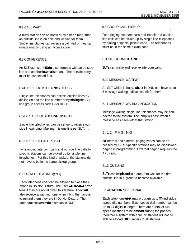
ENCORE SYSTEM DESCRIPTION AND FEATURES SECTION ISSUE 2. NOVEMBER 1988
8.2 CALL WAIT
A busy station can be notified (by a beep tone) thatan outside line is on hold and wafting for them.Single line phones can receive a call wait or they caninitiate one by using an access code.
6.3 CONFERENCE
An SLT user can a conference with an outsideline and another station. The outside partymust be connected first.
6.4 DIRECT OUTSIDE ACCESS
Single line telephones can access outside lines bydialing 88 and the line number or by the COline group access codes 9 or 81-86.
6.5 DIRECT OUTSIDE RINGING
Single line telephones can be set up to receive out-side line.ringing. Maximum is one line per SLT. .
6.6 DIRECTED CALL PICKUP
Tone ringing intercom calls and outside line calls tospecific stations can be picked up by single linetelephones. For this kind of pickup, the stations donot have to be in the same pickup group.
6.7 DO NOT DISTURB @ND)
Each telephone user can be allowed to place theirphone in Do Not Disturb. The user errortone if they are not allowed this feature. They also receive a warning tone when lifting the handsetto remind them they are in Do Not Disturb. Theattendant can a station in DND.
6.8 GROUP CALL PICKUP
Tone ringing intercom calls and transferred outsideline calls can be picked up by single line telephonesby dialing a special pickup code. The telephonesmust be in the same pickup zone.
6.9 INTERCOM
can make and receive intercom calls.
6.10 MESSAGE WAITING
An SLT which is busy, or in DND can have up to5 message waiting indications left for them.
6.11 MESSAGE WAITING INDICATION
Message waiting single line telephones may be con-nected to the system. The lamp will flash when amessage has been left at that station.
6 . 1 2 P A G I N G
internal and external paging zones can be ac-cessed by Specific stations may be disallowedpaging in programming. External paging requires theAPL card.
6.13 QUEUING
can be in a queue to wait for the firstoutside line in a group to become available.
6.14 SPEED DIAL
Each telephone may program up to individualspeed dial numbers. Each speed dial number can beup to 24 digits in length. There are a total of 640speed locations to be among the phones:therefore a system with a full 72 stations will not beable to allocate numbers to all stations.
101-7

SECTION 1 0 1 ENCORE CX 3672 SYSTEM DESCRIPTION AND FEATURES
6.15 SYSTEM SPEED
Each station user can be programmed for access system speed numbers. The last system speednumbers override toll restriction. Requires APL board.
6.16 TRANSFER
Outside lines may be transferred by or to Transfers can be either announced or unannounced.
6.17 UNIVERSAL NIGHT ANSWER (UNA)
When outside lines are marked UNA and the systemis placed into night service, an SLT can answer incom-ing calls on lines it does not normally have access to.An external ringing device must be provided.
7. DIRECT STATION SELECT (DSS)CONSOLE FEATURES
7.1 ATTENDANT OVERRIDE
The DSS console provides an Override key whichallows the attendant to ring a station in DND.
7.2 ATTENDANT SEARCH (SERIAL
An attendant can make a series of intercom callswithout hanging up. Intercom connection is to another station whenever a DSS key is and the previous intercom is
7.3 BUSY LAMP FIELD INDICATORS
Each station key on the DSS a correspondingLED which shows a station’s status. The LED is busy, unlit if idle and flashing in DND.
7.4 STATION INDICATION
The LED next to a calling station’s key rapidlyon the DSS, showing the attendant who is calling.
7.5 CAMP-ON (CALL WAIT)
The DSS has a Camp-On key, enabling the attendantto notify a busy station that a call is waiting for them.
7.6 DIRECT CALL PARK KEYS
The DSS has 3 Call Park keys, allowing the attendantto park up to 3 incoming calls by pressing a key.
7.7 DIRECT PAGE
The attendant can make an internal, external or sys-tem all call page by pressing 1 key. Automaticallyputs an outside caller on hold.
7.8 DIRECT STATION
The DSS attendant can make an intercom voice callto any key phone in the system. Automatically putsan outside call on hold while making an intercom call,Also allows an attendant to transfer an intercom oroutside call on to an internal station.
7.9 HUNT GROUPS
The DSS provides 3 hunt keys, the attendantto place a call to a hunt group by pressing a button.
7.10 MAPPING OPTIONS
a. MAP 36 appear in sequential order.b. MAP 2, stations 136-l 71 appear in sequential order.
MAP 3, CO appear in sequent&l order.MAP 4, stations appear in sequential order.Available only 36112 MAP 5, CO l-24 and 24 Requires Feature Package V Software.
7.11 RELEASE KEY
Allows the attendant to disconnect calls hook, speeding up call handling time.
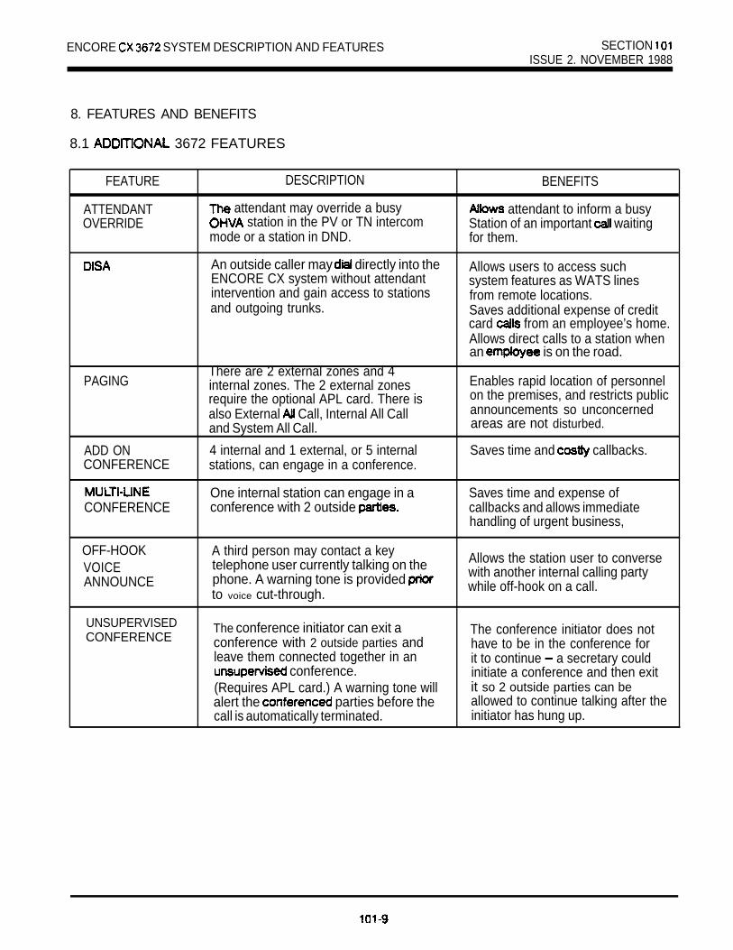
ENCORE SYSTEM DESCRIPTION AND FEATURES SECTION ISSUE 2. NOVEMBER 1988
8. FEATURES AND BENEFITS
8.1 3672 FEATURES
FEATURE
ATTENDANTOVERRIDE
DESCRIPTION BENEFITS
attendant may override a busy station in the PV or TN intercom
attendant to inform a busy
mode or a station in DND.Station of an important waitingfor them.
An outside caller may directly into theENCORE CX system without attendantintervention and gain access to stationsand outgoing trunks.
Allows users to access suchsystem features as WATS linesfrom remote locations.Saves additional expense of creditcard from an employee’s home.Allows direct calls to a station whenan is on the road.
PAGING
ADD ONCONFERENCE
CONFERENCE
There are 2 external zones and 4internal zones. The 2 external zonesrequire the optional APL card. There isalso External Call, Internal All Calland System All Call.
4 internal and 1 external, or 5 internalstations, can engage in a conference.
One internal station can engage in aconference with 2 outside
Enables rapid location of personnelon the premises, and restricts publicannouncements so unconcernedareas are not disturbed.
Saves time and callbacks.
Saves time and expense ofcallbacks and allows immediatehandling of urgent business,
OFF-HOOKVOICEANNOUNCE
A third person may contact a keytelephone user currently talking on thephone. A warning tone is provided to voice cut-through.
Allows the station user to conversewith another internal calling partywhile off-hook on a call.
UNSUPERVISEDCONFERENCE
The conference initiator can exit aconference with 2 outside parties andleave them connected together in an
conference.(Requires APL card.) A warning tone willalert the parties before thecall is automatically terminated.
The conference initiator does nothave to be in the conference forit to continue a secretary couldinitiate a conference and then exitit so 2 outside parties can beallowed to continue talking after theinitiator has hung up.
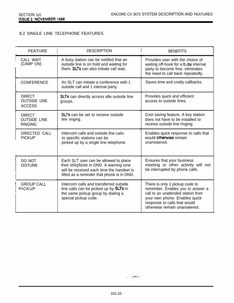
SECTION 101 ENCORE CX 3672 SYSTEM DESCRIPTION AND FEATURES
8.2 SINGLE LINE TELEPHONE FEATURES
iFEATURE DESCRIPTION BENEFITS
CALL WAIT(CAMP ON)
CONFERENCE
DIRECTOUTSIDE UNEACCESS
DIRECTOUTSIDE LINERINGING
DIRECTED CALLPICKUP
DO NOTDISTURB
GROUP CALL PICKUP
A busy station can be notified that anoutside line is on hold and waiting forthem. can also initiate cal! wait.
An SLT can initiate a conference with 1outside call and 1 internal party.
can directly access idle outside linegroups.
can be set to receive outsideline ringing.
Intercom calls and outside line callsto specific stations can bepicked up by a single line telephone.
Each SLT user can be allowed to placetheir telephone in DND. A warning tonewill be received each time the handset islifted as a reminder that phone is in DND.
Intercom calls and transferred outsideline calls can be picked up by inthe same pickup group by dialing aspecial pickup code.
Provides user with the choice ofwaiting off-hook for a internalparty to become free: eliminatesthe need to call back repeatedly.
Saves time and costly callbacks.
Provides quick and efficientaccess to outside lines.
Cost saving feature. A key stationdoes not have to be installed toreceive outside line ringing.
Enables quick response to calls thatwould remainunanswered.
Ensures that your businessmeeting or other activity will notbe interrupted by phone calls.
There is only 1 pickup code toremember. Enables you to answer acall to an unattended station fromyour own phone. Enables quickresponse to calls that wouldotherwise remain unanswered.
101-10

ENCORE CX 3672 SYSTEM DESCRIPTION AND FEATURES SECTION 101ISSUE 2. NOVEMBER 1988
8.2 SINGLE LINE TELEPHONE FEATURES (CONT’D)
r FEATURE DESCRIPTION BENEFITS
INTERCOMCALLING
MESSAGE
MESSAGEWAITINGINDICATION
PAGING
QUEUING
STATIONSPEED DIAL
SYSTEMSPEED DIAL
TRANSFER
UNIVERSALNIGHTANSWER
can make and receive intercomcalls.
An SLT which is busy, idle or in DNDcan have up to 5 messages left for them.
Message waiting may be connectedto the system. A lamp will flash whena message has been left.
All internal and external paging zonescan be accessed by if programmedto do so.
can be placed in a queue awaitingan outside line in a specific group tobecome available.
Each SLT may program up to 20individual speed dial numbers.Maximum 640 per system.
Each SLT can be programmed to system speed dii numbers. The last 40system speed dial numbers override tollrestriction.
Outside lines may be transferred toanother station by or transferred byother stations to an SLT.
When outside lines are marked UNAand the system is placed in night an SLT can answer incoming callsby dialing “77”.
An SLT can be used in place of akey telephone in the system.Provides an inexpensive phonealternative in areas where not alllines and features of a key phoneare required.
Eliminates the need to repeatedly a station; the station you
called can call you backwhen available.
Lets you know that someonewishes to talk to you; they do nothave to call back repeatedly.
Enables rapid location ofpersonnel on the premises.Saves time and expensivecallbacks.
Saves time because you do nothave to keep repeatedly trying abusy line group to see if it isavailable yet.
Increases productivity byeliminating time wasted oncontinually redialing frequentlycalled numbers. .
Increases productivity byeliminating time wasted onmulti-digit dialing of frequentlycalled numbers common to theentire system.
I
Expedites efficient call handling.
Allows any station to answeran incoming call by simply dialinga code.
101-l 1

SECTION 101 ENCORE CX 3672 SYSTEM DESCRIPTION AND FEATURESISSUE NOVEMBER
8.3 DIRECT STATION SELECT (DSS) CONSOLE FEATURES
FEATURE
DIRECTSTATIONCALLING
DIRECTPAGE
RELEASEKEY
ATTENDANTSEARCH
INDICATORS
DIRECT CALLPARK KEYS
CALLINGSTATIONINDICATION
ATTENDANTOVERRIDE
ATTENDANTRECALL
DESCRIPTION
Enables DSS attendant to make anintercom voice call to any station in thesystem by pressing only 1 button.Also permits attendant to put outside callon hold and simultaneously makeintercom call to internal station.
Permits attendant to page one of 3 zoneswith single depression of a button.Attendant can also automatically placean outside call on hold and make a page.
Allows attendant to disconnect callswhile off-hook and go on to a new call.
Permits an attendant to transfer anintercom or outside call which is on holdto an internal station in the system.Allows attempt of one transfer afteranother simply by pressing anotherDSS key.
Each station appearing on the DSSconsole has a corresponding indicatorwhich shows whether the station is idle,busy or in DND.
3 direct Call Park keys enable theattendant to park up to 3 incoming callssimply by pressing a single key.
The indicator next to the calling station’skey will flash rapidly on attendant’sDSS console.
The attendant may signal a stationin DND.
When a station fails to respond to a holdrecall, the recall will automatically revertto the attendant.
BENEFITS
Allows rapid handling of incomingtraffic and avoids the expense ofcallbacks and annoying no answer for customers.
Direct page keys simplify thethe paging procedure and savethe attendant valuable time.
Speeds call handling.
Simplifies the call transfer process.
Allows an attendant to see at aglance which stations in thesystem are busy and to inform thecaller immediately and take a
Expedites call handling byeliminating the need for attendantto dial multi-digit codes.
Allows DSS attendant to seewhich station in the system iscalling and respond immediately.
By pressing 1 key the attendantcan inform a busy station of animportant or emergency call.
Assures that a calling party isneither forgotten nor forced towait too long about his/her call’sstatus.
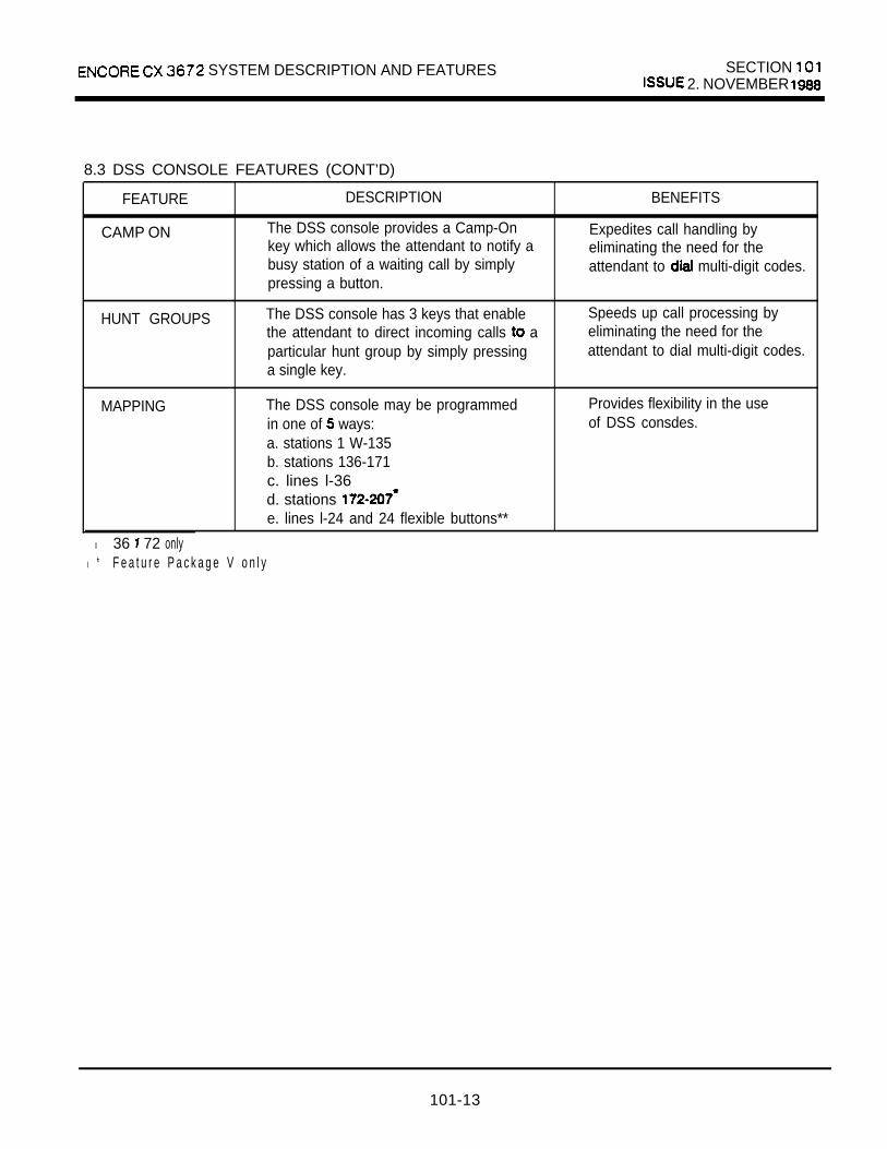
SYSTEM DESCRIPTION AND FEATURES SECTION 2. NOVEMBER
8.3 DSS CONSOLE FEATURES (CONT’D)
FEATURE
CAMP ON
DESCRIPTION
The DSS console provides a Camp-Onkey which allows the attendant to notify abusy station of a waiting call by simplypressing a button.
BENEFITS
Expedites call handling byeliminating the need for theattendant to multi-digit codes.
HUNT GROUPS The DSS console has 3 keys that enable Speeds up call processing bythe attendant to direct incoming calls a eliminating the need for theparticular hunt group by simply pressing attendant to dial multi-digit codes.a single key.
MAPPING The DSS console may be programmedin one of ways:a. stations 1 W-135b. stations 136-171c. lines l-36d. stations e. lines l-24 and 24 flexible buttons**
Provides flexibility in the useof DSS consdes.
l 36 72 onlyl * F e a t u r e P a c k a g e V o n l y
101-13

SECTION 101 ENCORE CX 3672 SYSTEM DESCRIPTION AND FEATURES
9. FEATURE PACKAGE V
The following additional features are provided byFeature Package V software installed on theEnhanced Processor Board (EPB). Feature PackageV also provides all the features available in ProgramModule 3 (PM-3) in the CX 616 system. See
for features. The Central ProcessorBoard (CPB) not support Feature Package Vsoftware.
10. STATION FEATURES (FP5)
10.1 ADDITIONAL STATION SPEED DIAL BINS
Feature Package V software expands the total numberof available station speed dial bins in the system from640 to 1260. A station still will be able to store andaccess a maximum of 20 station speed dial numbers.
10.2 AUTOMATIC HOLD
A station user can automatically put one CO call onhold by selecting a second CO line. For ifyou are talking to outside party A, you can make oranswer another outside call by pressing another COline button. Party A will be put on hold automatically.This system-wide option makes it easier and faster tohandle multiple calls. This feature is denied in default.The type of hold (system or exclusive) is determinedby the system’s Hold Preference.
10.3 CALL FORWARD OFF PREMISE
Stations can intercom and transferred COcalls to an off-premise location. a to reroute calls that normally lost: cannow be forwarded to home or another off-premisesite. ringing CO cannot be forwardedwith this feature.
10.4 CUSTOM MESSAGES
Up to ten (10) custom messages can be programmedsystem-wide by the first attendant station. Thesemessages supplement the ten available pre-selectedmessages. A station user can leave any of the custommessages on his/her phone. The message bedisplayed on the LCD of an internal party calling thatstation. Custom messages can contain up to 24characters.
10.5 DAY/NIGHT CLASS OF SERVICE (COS)
Allows stations to have a different COS at night thanthey have during the day. When the attendant putsthe system into night service mode, stations go totheir programmed night COS. Prevents the misuse ofphones after hours.
10.6 DIRECTED CALL PICKUP OF AN INTERCOMPHONE BOX
Allows you to pick up an intercom call that has beenmade to an intercom phone box.
10.7 DISPLAY ‘SECURITY
Allows a station user to program a numberthat not appear on the phone’s LCD when
This feature is in applications wheresecurity access codes or codes must
The number to be kept is stored in aspeed bin.
10.8 FORWARDING CALLS TO UCD, HUNT ANDVOICE GROUPS
Enables a to forward busy no answercalls, and both busy/no answer to a UCD, huntor voice group. Initially ringing CO cannotbe forwarded to these groups.

ENCORE CX 3672 SYSTEM DESCRIPTION AND FEATURES SECTION 101
10.9 LEAST COST ROUTING PRIORITY
Allows route entry priorities to be assigned on a perstation basis. This allows or disallows specific sta-tions the ability to access certain trunk groups. InLCR admin programming, each trunk group in theroute entry of a route list can be assigned a prioritynumber. The highest priority number is 1 and thelowest is 7. Ttiis number, when compared against thestation’s LCR priority number (specified in stationprogramming), determines whether or not a stationcan access a trunk group. If the station LCR COSnumber is higher than or equal to the LCR routepriority number, access to that group in that entry isallowed.
10.10 PROGRAMMING YOUR NAME INTO THE LCDDISPLAY
In previous software, the letters and could notbe programmed into a station’s LCD display. FeaturePackage V software now allows and
11 REMOTE MAINTENANCE
The Remote Maintenance feature allows authorizedpersonnel to survey system and configuration in-formation. This can be done through a modem ordata terminal connected to the system EPB theRS-232 port. The commands are entered from thekeyboard of the remote terminal device.
10.12 REMOTE PROGRAMMING
The Remote Programming feature authorizedpersonnel to the mode via a terminal device (portable terminal or personal computer with package).The feature permits the review and entry of thecustomer data base in the same manner vie thetelephone at extension The terminaldevice can be connected directly to the RS232connector on the or can be accessed by atelephone modem linking the RS232 connector(via a CO line) to a remote location.
10.13 TRUNK GROUP ACCESS ON CALLS
callers can now select an outgoing line via agroup dial code (9-88) or via an individual line dialcode. LCR is not available through DISA. In systemswhere LCR is activated. callers must dial toaccess group 1 (instead of dialing 9).
10.14 UCD AGENT IN/OUT
A station user can remove from a group without placing his/her phone in DND. By dial-ing a special code the station user no longer receivesUCD calls but will receive other calls. The code canalso be programmed under a flex button. This featureis also available to SLT users.
10.15 UNIFORM CALL DISTRIBUTION (UCD)
As its name implies, Uniform Call Distribution is ameans of routing an equal number of calls to station in a group. This is accomplished by placingthe lest station to receive a call at the end of thegroup’s list. For example, if stations and 3 are ina call group, and 1 handles a call and thenhangs up, station 1 is placed at the end of the group’slist. Station 2, followed by station 3, will be the next toreceive calls. Incoming CO calls, transferred CO and intercom calls can all be routed to a group.
Up to eight (8) groups can be in thesystem. Each group can contain up to (8)
An alternate group and an overflow position
Recorded announcement devices can be assigned toprovide up to two (2) The mes-sages are available to all (8) groups.

SECTION 101 ENCORE CX 3672 SYSTEM DESCRIPTION AND FEATURESISSUE 2. NOVEMBER 1988
10.16 VOICE MAIL
The voice mail feature automatically handles un-answered calls. Messages can be retrieved by stationusers directly from the system with no assistance fromthe attendant. Up to eight (8) voice mail groups canbe configured in the system. Each group can containup to eight voice mail stations, each of which inter-faces with a port on a SIB board. Each mail
can be shared by a number of actual users.Transferred CO calls and intercom calls can be routedto a voice mail group. An optionally mail system must be connected to the ENCORE CXfor this feature to be available.
The ENCORE CX has special codes assigned, ena-bling voice mail systems to turn on and off messagewaiting indication at users’ stations.
11. FEATURES
11.1 CUSTOM MESSAGES
The first attendant station can program up to ten (10)custom messages that are available to station users.
11.2 DSS/DLS CONSOLE MAP
A fiih map is now available for the Direct StationSelection Line console.The new map provides 24 fixed CO buttons and 24flexible buttons. Map 5 is programmed admin, butflexible buttons are programmable by stations. following features cannot be programmed under aflexible button on Map 5: loop button, dial memo,voice mail groups, CO lines, and hold.
11.3 FORWARDING INCOMING CO CALLS OFFPREMISE
Allows the first attendant to forward incoming CO callsto an off-premise location. The attendant must have adirect appearance of the CO line to be This feature requires the optional APL card.
11.4 SELECTING BACKGROUND MUSIC AT ANINTERCOM PHONE BOX
The first attendant station can turn on backgroundmusic at an intercom phone box . No music, musicchannel 1 or channel 2 can be selected from the atten-dant station. In earlier software versions this could beaccomplished only through admin programming.
12. SLT FEATURES
12.1 ACCOUNT CODES
SLT stations can now enter account codes to identifycalls for billing/tracking purposes. The account codewill be recorded on the SMDR printout.
12.2 PROGRAMMING YOUR NAME
Permits you to program your name on your SLTstation. When a station with a display calls you,’ yourname (not your station number) will appear on the ing station’s LCD. Your name is stored in bin 00. Thisreduces, from 29 to 19, the total number of stationspeed bins available to you.
FIGURE 3. MAP 5
101-16

ENCORE 3672 SYSTEM DESCRIPTION AND FEATURES SECTION 01ISSUE 3. NOVEMBER
13. FEATURE PACKAGE VI(FP6)
The following feature descriptions are provided byFeature Package VI in addition to features which existin Feature Package V. This feature package is a com-posite of all previously described features for PM-l,PM-2, of the Encore CX 816 systemand SLT Features defined in section 102. FeaturePackage VI is offered in the same four versions asFeature Package V.
2886301
2 9 9 6 3 0 3
ENCORE CX BASIC EPB EPB software
package to support the basic system fea-ture set for the system.
ENCORE CX 1832-3672 EPBSOFTWARE WITH LCR
EPB software pack-age to support the basic system featureset for the 1832-3672 system with LeastCost Routing (LCR).
ENCORE CX 183236112 BASIC EPB .SOFTWARE (SOFT/361 12). EPBsoftware package to support the basksystem feature set for the 183286112system.
ENCORE CX 183286112 SOFTWARE WITH LCR
EPB software pack-age to support the basic system feature
Cost Routing
These software must be on the En-hanced Processor Board The CentralProcessor Board (CPB, will not support Fea-ture Package VI.
14. SYSTEM FEATURES: (FP6)
1 4 . 1 PROGRAMMABLE KEY STATIONANNOUNCE TONE
The key telephone intercom announce tones canhave three different modes. By default, the standard 3tone bursts handsfree announce tone is provided.The other two options are 1 tone burst and no tonepreceding voice cut-through. This is assigned in ad-ministration programming using the FLASH 45 code.It is system wide and cannot be changed by the sta-tion user.
14.2 LCR ROUTING FOR TOLLINFORMATION CALLS
This feature allows for common call routing for all tollinformation calls. Both 1 -XXX-555-l 212 and xXx-555-1212 calls will be intercepted and sent to a selectedroute. If determined to be a information call withan area code, the call will be sent to the route list as-signed in programming for LCR.
1 4 . 3 FLEXIBLE UCD NEW CALL TIMER
The duration of the UCD agent new call timer can beflexibly assigned in programming. At the end of eachUCD call, the UCD agent will be idle for the durationof the New Call timer. This allows the agent to accessother facilities (such as IN/OUT, DND or make a call)before being subject to calls again. The timer isset in administration programming using 37
is 4 seconds.
1 4 . 4 EXPANDED CO RINGING ASSIGNMENT
Each CO line may be programmed so that ringing CO calls may be assigned to one of the follow-ing destinations: to one or more or
to a UCD, Mall, Hunt Group, or to a tern Speed Bin for off-net call
1 0 1 - 1 7
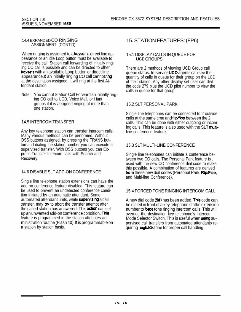
SECTION 101 ENCORE CX 3672 SYSTEM DESCRIPTION AND FEATURESISSUE 3, NOVEMBER
14.4 EXPANDED CO RINGINGASSIGNMENT (CONT’D)
When ringing is assigned to a a direct line ap-pearance or an idle Loop button must be available toreceive the call. Station call forwarding of initially ring-ing CO call is possible and can be directed to other
with an available Loop button or direct lineappearance. an initially ringing CO call cannot at the destination assigned, it will ring at the first At-tendant station.
Note: You cannot Station Call Forward an initially ring-ing CO call to UCD, Voice Mail, or Huntgroups if it is assigned ringing at more thanone station.
14.5 INTERCOM TRANSFER
Any key telephone station can transfer intercom calls.Many various methods can be performed. WithoutDSS buttons assigned, by pressing the TRANS but-ton and dialing the station number you can execute asupervised transfer. With DSS buttons you can Ex-press Transfer Intercom calls with Search andRecovery.
14.6 DISABLE SLT ADD-ON CONFERENCE
Single line telephone station extensions can have theadd-on conference feature disabled. This feature canbe used to prevent an undetected conference condi-tion initiated by an automatic attendant. Someautomated attendant units, while a calltransfer, may to abort the transfer attempt afterthe called station has answered. This can setup an unwanted add-on conference condition. feature is programmed in the station attributes ad-ministration routine (Flash 40). is programmable ona station by station basis.
15. STATION FEATURES: (FP6)
15.1 DISPLAY CALLS IN QUEUE FOR GROUPS
There are 2 methods of viewing UCD Group callqueue status. In-service agents can see thequantity of calls in queue for their group on the LCDof their station. Any other display set user can dialthe code 279 plus the UCD pilot number to view thecalls in queue for that group.
15.2 SLT PERSONAL PARK
Single line telephones can be connected to 2 outsidecalls at the same time and between the 2calls. This can be done with either outgoing or incom-ing calls. This feature is also used with the SLT line conference feature.
15.3 SLT MULTI-LINE CONFERENCE
Single line telephones can initiate a conference be-tween two CO calls. The Personal Park feature is .used with the new CO conference dial code to makethis possible. A combination of features are derived
these new dial codes (Personal Park, and Multi-line Conference).
15.4 FORCED TONE RINGING INTERCOM CALL
A new dial code has been added. code canbe dialed in front of a key telephone statbn extensionnumber to tone ringing intercom calls. This willoverride the destination key telephone’s IntercomMode Selector Switch. This is useful when su-pervised call transfers from automated attendants re-quiring tone for proper call handling.

ENCORE 36112 SECTION 102FIELD CONVERSION KIT ISSUE 1, JULY 1968
ENCORE CX 36112 SYSTEM DESCRIPTION AND FEATURES
1. SYSTEM DESCRIPTION
The ENCORE CX 36112 Field ConversionKit (2993505) is designed for themedium-to-large size business market.It supports a maximum of 36 outsidel ines and in terna l te lephonestations. The Field Conversion Kit‘includes the following: oneExpansion KSU and one power cage.The Expansion KSU is installed inaddition to the Basic KSU used in the3672 system, and replaces the 3672Expansion KSU. Adding this equipmentmakes the ENCORE CX 3672 systemexpandable to an ENCORE CX 36112system. The 36112 is a modularexpandable system with all of thesame features as the ENCORE CX 3672system.
All of the peripheral cards in the3672 are interchangeable 36112. I n s t e a d o f theProcessor Board (CPB) the 36112 usesthe Enhanced Processor Board (EPB).Depending on the software ordered andinstalled separately, the EPB canprovide CX 36112 features or 38112features and Least Cost Rout ing(LCR). The (Expanded InterfaceBoard) expands the intercomcapability from one group of 8 pathsto 2 groups of 8 paths, bridges thetwo intercom groups, and enhancesprocessor capability.
Customers who are upgrading from the3672 system will find that theirexisting ENCORE CX phones can be usedin the 36112 system.
The D i rec t S ta t ion /L ine Se lec tor(DSS) console used in the 3672system can continue to be used inthe 36112 system. An additional maph a s b e e n a d d e d t o i n c l u d e t h eincreased number of stations
2 EQUIPMENT DESCRIPTION
A basic system (required for systemoperation) must include thefollowing:
Basic KSU (same as 3672)Enhanced Processor BoardExpanded Interface BoardCentral Office Interface
BoardKey Telephone InterfaceB o a r dPower Supply (24 volt)
Converter36112 Field Conversion Kit
Section 101 discusses all of theseunits except the Enhanced ProcessorBoard (EPB), Expanded InterfaceBoard and the 36112 Field
Conversion Kit.
102-l

SECTION 102 ENCORE CX 36112 SYSTEM DESCRIPTION AND FEATURESISSUE 1 , JULY 1988
2.1 ENHANCED PROCESSOR BOARD(EPB) AND FOR36112 FEATURES
The Enhanced Processor Board (EPB,2994402) replaces the Cent ratProcessor Board (CPB, 2994401) in theKSU. The EPB is shipped withoutsoftware. The capabi l i t ies of theEPB card are cont ro l led by thesoftware package installed on thecard. The software enabl ing the36112 features is a PROM chip set(2996302) that is installed on theEPB. Software providing 36112features and Least Cost Routing (LCR)is also available (2996303). Referto Sec t ion 701 in the Techn ica lManual for LCR information.
2.2 EXPANDED INTERFACE BOARD
The (Expanded Interface Board) isan extension of the processorcapabil it ies. The EIB expands thetotal number of intercom links in thesystem from one group of 8 paths totwo groups of 8 paths. The EIBconnects the 8 intercom paths fromthe Basic cabinet to s lots
Switching is allowed betweenthe 2 groups through the
In addition, i f a business’ hasunusually heavy intercom use, thelast CO line card can be removed andthe matrix paths for that card can beused as intercom paths instead (adds6 paths). This will be controlled bysoftware.
2.3 POWER SUPPLY
This unit supplies the 24 volt powerrequired for system operation. Onepower supply is required for the
Basic KSU; a second power supply isrequ i red i f 5 -8 , the secondAPL, the EIB 4-6 areadded to the Expansion cabinet.
If more than 56 stations areinstalled and/or KIB slots 15through 21 are used, a third powersupply is required. The third powersupp ly is ins ta l led in the powercage mounted to the right of theBasic KSU.
2.4 DC/DC CONVERTER
A modular unit that converts the 24VDC power into the system 5 VDC and14 VDC voltages.
T h e f i r s t D C / D C c o n v e r t e r w i l lsuppo r t t he en t i r e sys tem un t i lcards are installed into KIB slots15 through 21. Then the second .
converter must be installed.
2.5 DIRECT STATION SELECTION(DSS) CONSOLE
Fully modular console thatprovides for direct one-buttonaccess to stations and 12 fixedfeature buttons. Three units can beconnected to provide access to 108stations. The DSS station buttonscan also be programmed for directline access for lines l-36. Up to 4DSS units can be associated with akey telephone.
3. OPTIONAL EQUIPMENT
R e f e r t o Section 101 for adiscussion of optional equipment.

ENCORE CX 36112 SYSTEM DESCRIPTION AND FEATURES SECTION 102ISSUE 1. JULY 1988
3.1 36112 EXPANSION KSU
The Expansion KSU is housed in a wallmount cabinet and contains card slotsfor 18 lines, 80 stations, thesecond APL, the EIB, third power
and the second DC/DCconverter. The Expansion cabinet isins ta l led to the r igh t above theBasic KSU.
3.2 SECOND APL CARD
When a 36112 is configured with twoAPL cards (both wi th RSM uni tsadded), a total of twelve (12) DTMFreceivers and six (6) senders areavailable. DTMF receivers andsenders are required for unsupervisedconference, and Single LineTelephone appl icat ions. Thedecision to use a second APL cardshould be based on the usage ofunsupervised conferences, DISA,and/or in the system.
The matrix in Table 1 shows maximum numbers of SLT stations thatcan be supported in the system, andthe cards required to support thoseconfigurations. I t a lso shows thenumber of DTMF senders and receiversprovided by APL cards with andwithout
4. EPB ADDITIONAL SYSTEMFEATURES
4.1 STATION MESSAGE DETAILRECORDING BAUD RATE
A new option on the port of theEPB enables 4800 baud for SMDR and
data base printing. Only 300 and1200 baud were allowed previously.Default is 4800 baud.
4.2 PROGRAMMABLE PAGEWARNING TONE
A page warning tone may be broadcastbefore a (internal andexternal), i f desired. By default,page warning tone is allowed.
4.3 SLT RING CADENCE
Ring burst duration on SLT stationsfor incoming CO calls is one (1)second. Th is makes the sys temcompat ible with devices such asmodems and FAX machines that requirea one (1) second burst for detection.
5. EPB SLT STATION FEATURES
5.1 ANSWERING CAMP-ONS ATSLT STATIONS
SLT stations can transfer a CO callin progress before answering a.second call.
5.2 CANCELLING CALL FORWARDOR DND FROM AN SLT
Allows you to cancel call forward orDND on your SLT station with justone code to remember. This featureis especially convenient if you’veforgotten whether you programmed DNDor call forward.
ENCORE CX 8 SECTION 200KEY TELEPHONE SYSTEM ISSUE 1, MAY 1987
ENCORE CX 816 OPERATING INSTRUCTIONS
1. INTRODUCTIONThe ENCORE CX 816 Key Telephone System hasa wide variety of features and flexible programming,allowing each telephone user to program his/hertelephone to meet own individual needs.
This section of the manual contains the operatinginstructions for key telephone users and includesillustrations of key telephones used in the ENCORECX 816 system and descriptions of the keys on thetelephones and their functions.
This section is designed to provide step-by-stepinstructions for operating the key telephones in thesystem. Visual and audible cues which accompanythe various steps in the operation of the feature arealso included.
Literature similar to these operating instructions hasbeen prepared for use by the customer in the formof Station, Attendant, and SLT User’s Guides.
2. KEY TELEPHONE STATION FEATURESEach ENCORE CX 616 key station provides thefollowing keys, indicators and features:
HANDSET AND SPEAKER are located at the leftside of the front panel. A handset is provided toallow confidential conversation when desired. .Lifting the handset from its cradle (going off-hook)disengages the station’s built-in speaker.The speaker is located below the centerportion of the handset. The may be operatedwith the handset on-hook. When this occurs, audio istransmitted to the station user through the station’sspeaker.
OUTSIDE CALLS are announced by a tone signalrepeated every 3.2 seconds. The correspondingoutside line indicator will flash slowly.
INTERCOM CALLS can be tone ringing or voiceannounced. If it is voice announced, the receivingstation will receive 3 bursts of tone prior to theannouncement. If it is a tone ringing call, thereceiving station will hear a tone ring every 2.4seconds.
FLEXIBLE BUTTONS are used to access idleoutside lines, provide for internal stations,access speed dial numbers and activate features.These buttons are programmed by the individualstation user.
MONITOR (MON) button enables you to make atelephone call without lifting the handset. It turns thetelephone on and off when using the speakerphone.
HOLD button enables you to place an outside calleron hold.
button is used to terminate an outside calland restore dial tone without having to hang up thehandset. It is also used to transfer calls behind aPBX or within those systems and tocomplete the programming of flexible buttons.
CONFERENCE (CONF) button is used to establishconference calls.
TRANSFER (TRANS) button is used to transfer anoutside call from one station to another.
MUTE button allows you to switch the built-inmicrophone on or off when using the speakerphone,or the handset microphone when using the handset.
button serves a function of allowingyou to place your telephone into Do Not Disturbor allowing you to your phone calls toanother station.
CALLBACK button allows you to leave an automaticcallback message at another station and return amessage left for you by another station. It also allowsyou to queue for an outside line.SPEED button provides you with access to speeddialing, save number and last number redial.
200-l
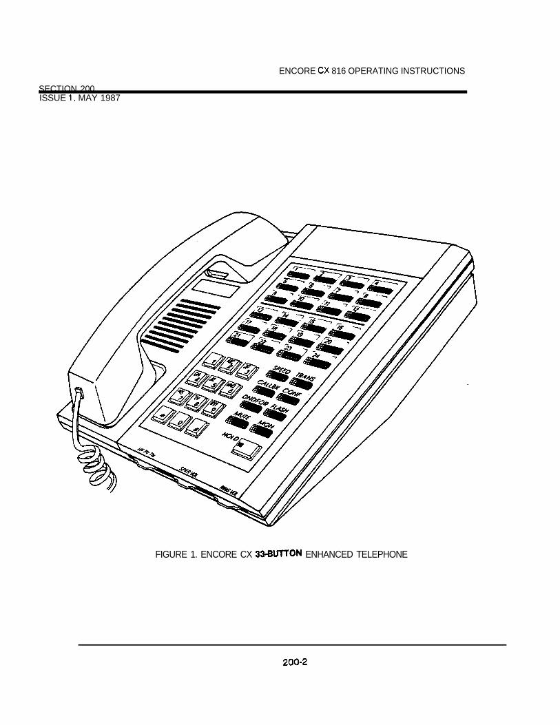
SECTION 200
ENCORE 816 OPERATING INSTRUCTIONS
ISSUE MAY 1987
FIGURE 1. ENCORE CX ENHANCED TELEPHONE
ENCORE CX 8 1 6 OPERATING INSTRUCTIONS SECTION 200ISSUE MAY 1987
2.1 PLACING AN OUTSIDE CALL
a. Press outside line button or pool button.(MON button lights)
b. desired party.c. When called party answers, lift handset for
privacy or use speakerphone.
Station user can also dial 88 and the individualoutside line number to access a particular outsideline. Dialing a number in the numbering plan activatesthe speakerphone automatically.
2.2 ANSWERING AN OUTSIDE CALLa. Press flashing outside line button or loop button.
(If your telephone has been programmed withRinging Line Answer, you may answer an outsideline by just lifting the handset.)
or use speakerphone bybutton.
2.3 MUTE BUTTON(Provides privacy during speakerphone orhandset operation by disabling the
microphone. )
a. Press to activate (button lights).b. Press again to deactivate
(button extinguishes).
The mute feature automatically deactivates upon calltermination.
2.4 SPEAKERPHONEa. Pressing an outside line button, a speed button,
a station button, or dialing a number in thesystem numbering plan will automatically activatethe speakerphone and light the monitor key your set is programmed as a speakerphone.NOTE: For further references in this section
where “lift handset” is specified,you may also use the method ofpressing key if the telephoneis programmed to be a true two-wayspeakerphone.
2.5 PLACING A CALL ON HOLDIf your system is programmed to have exclusivehold preferred press once for exclusive holdand twice for system hold.
2.6 ANSWERING A RECALL
a. When an outside line has remained on holdfor an extended period of time, you will bereminded with a recall ring.
b. Press outside line, loop or pool buttonflashing at a very fast rate.
c. Lift handset to converse.
If you do not answer a recall within a programmedperiod of time, the call will be transferred to theattendant.
2.7 GROUP LISTENINGOne person can speak through the handset whileothers can listen to the connected party through thetelephone speaker.a. Lift handset and dial desired party.b. While connected to the other party,
press (the key lights).c. The voice of the other party will come through
the speaker.
2.8 PLACING AN INTERCOM a. intercom number or press the
preprogrammed station button.b. You will hear:
1. tones if the called station is in theTN mode. Wait for called station to answer.
2. 3 bursts of tone if called station is in the HFor PV mode. Begin your announcement afterthe tones.
Intercom boxes are called by dialing correspondingintercom number or pressing the preprogrammed
station button.
NOTE: a number in the number planactivates the telephone automatically.
200-3

SECTION 200 ENCORE CX 8 16 OPERATING INSTRUCTIONSISSUE MAY 1987
2.9 ANSWERING AN INTERCOM CALLWith your intercom signal switch in the:a. TN position, you will hear intercom ringing.
handset or move selector to HF to reply.b. PV position, you will hear of tone and a
one-way announcement. Lift handset or switchintercom selector to HF to reply.
c. HF position, you will hear 3 bursts of tone andan announcement. Reply handsfree or lifthandset for privacy.
2.10 BACKGROUND MUSICa. Remain on-hook.b. Dial or press preprogrammed feature
access button.c. To remove the music, dial or press
the preprogrammed feature access button.
2.11 flash disconnects present outside line and restoresoutside line dial tone.a. While connected to an outside line,
press The duration of the flash is automatically timed.Therefore, the length of time the button is held doesnot affect the function.A station denied access to a line can receive atransfer and make a transfer but cannot on thatline.
2.12 CALL TRANSFERa.
b.
C.
While connected to an outside line,press The call is put on exclusive hold.Dial station number ( 100-l 7 1) pressappropriate preprogrammed stationbutton.At this point you can make either a screened orunscreened transfer.
SCREENED TRANSFERa. The called extension is b. When the extension announce transfer.c. Hang up to complete transfer.
UNSCREENED TRANSFERa. When the called extension begins to ring,
hang up to transfer call. (Recall timer starts.)
ANSWERING SCREENED TRANSFERa. After the transferring internal party hangs up,
press outside line button flashing on hold toaccess the transferred outside call.
2.13 EXECUTIVE/SECRETARY TRANSFERa. If you are designated the Executive station and
your phone is busy or in DND, all calls will berouted to your programmed Secretary station.
b. If you are designated the Secretary station,you can signal the Executive that is busy or inDND by using the Call Wait feature.
2.14 DO NOT DISTURBIf your phone has been programmed to have
Not Disturb:a. Press while on-hook or while your
phone is ringing. The button will light.Your telephone will be placed in Do Not Disturband ringing will be silenced.NOTE: Attendant station has no DND.
REMOVING DO NOT DISTURBa. Press while on-hook. The LED
extinguishes.
2.15 CALL WAIT (CAMP-ON)You call an extension that is busy to them toyour call.a. After receiving intercom tone, press
preprogrammed CALL WAIT button or station will receive 1 burst of ringing.
b. When called answers, consult with them orhang up to transfer the call.
200-4

ENCORE CX 8 16 OPERATING INSTRUCTIONS 200ISSUE MAY 1987
ANSWERING A CALL WAITIf you hear 1 burst of ringing and your button is ,a. Press HOLD to consult with calling station.
you have a call waiting for you.
First call will be placed on hold.b. Press flashing outside line button if a call is being
transferred.NOTE: An internal caller cannot be put on hold.
Pressing the will cause aninternal call to be dropped.
2.16 PAGINGIf you have been given the ability to make pages:a. Lift handset.b. Dial desired page zone. Your will hear warning
tone.c. When the tone ends, make your page
announcement in a normal tone of voice.d. Hang up when you are finished paging.
PAGE ZONES
All CallInternal Zone 1Internal Zone 2Internal Zone 3 (3672 only)Internal Zone 4 (3672 only)Internal All CallExternal Zone 1External Zone 2External All Call
(3672 only)(3672 only)
Phones in DND will not receive pagingannouncements. When making an All Call page,the page initiator will get tone if any zoneis busy. tone continues zonebecomes available. You will then hear a toneand can make your page.
2.17 MEET ME PAGE.a. lift handset.b. desired page zone.c. Request that the desired party meet you on the
d. Wait for called party to answer(DO NOT hang up).
As soon as the paged party answers and isconnected to you, the page circuit is freed.
ANSWERING A MEET ME PAGEa. Go to nearest key telephone.b. You are connected to party who
paged you.
2.18 CALL FORWARDa. handset or press b. .c. Dial station number or press the preprogrammed
button of the station to which calls willbe button flashes)
d. Hang up or press Line queues, callback request, message waitrequests and preselected messages are cancelledwhen a station places itself in forward.Callback requests are not allowed at the stationwhere a call is forwarded. CO line calls can betransferred by the receiving station back to theoriginal station. A station in call mode canstill make outgoing calls.
REMOVING CALL FORWARDa. Lift handset or b. Press The
extinguishes.c. Hang up or press
button
2.19 MESSAGE WAITINGUp to 5 messages can be left at one telephone.a. If you dial a telephone that is unattended or in
DND, you can leave a callback request.b. After receiving DND tone or no answer,
button. Your will hearconfirmation tone.
c. Hang up or press
ANSWERING A MESSAGE INDICATION
a. Press flashing button.b. Station that left message will be signalled with
tone ringing.The button will continue to flash until allmessages have been answered. First message leftwill be first one
200-5
SECTION 200 ENCORE CX 816 OPERATING INSTRUCTIONSISSUE MAY 1987
2.20 CALLBACKIf you dial a telephone that is busy, you can leavea callback indication.a.
b.C.
d.
When the busy station hangs up, you will besignaled.When you have answered the callback signalby lifting handset or pressing MON button, thestation you originally called will be signaled.
2.21 DIRECTED CALL PICKUPa. You hear intercom or outside line
ringing at a particular station.b. Lift handset.
Dial d. Dial station number of the ringing phone.e. You will be connected automatically to the
calling party.You must have access to the specific outside line or Loop key to do a directed call pickup.
2.22 GROUP CALL PICKUPa. You hear an unattended phone in your group
ringing.b. handset.c. Dial d. You will be connected automatically to the
calling party.You must be in the same pickup group.
2.23 CALL PARKAllows you to place an outside on hold andconsult with, page or an internal party and/ortransfer the outside call.a. While connected to an outside line,
press The caller is put on exclusivehold.
b. Dii parking location Hear confirmation tone.
c. If you hear busy tone, press and diianother parking location.
RETRIEVING A PARKED CALLa. handset or press b. Dial q .c. Dial parking location.
2.24 CONFERENCE
NPES OF CONFERENCEa. Add-On: 1 outside party and 2 internal parties.b. Multi-Line: 1 internal party and 2 outside parties.
A CONFERENCEa.b.
Call internal or outside party.Press Button lights and party is placedon exclusive hold.
EXITING AN ADD-ON CONFERENCEa. Hang up, or press .
Conference remains active.
RE-ENTERING AN ADD-ON CONFERENCEa. handset or press b. Press
TO DROP AN OUTSIDE a. You must be actively in the conference.b. Press outside line of arty you wish to drop.c. Hang up or press MON .d. Re-enter the conference.
TERMINATING AN ADD-ON CONFERENCEa. Hangu.b. Press CONF .
TERMINATING A MULTI-LINE CONFERENCEa. Hang up.
2.25 NUMBER
1. Svstem will automatically select the originalline used to place the and redial thenumber.
2. If that line in busy, the system willautomatically select another line from thesame group and redial the number.

ENCORE CX 8 16 OPERATING INSTRUCTIONS SECTION 200ISSUE MAY 1987
2.25 LAST NUMBER (CONT’D)
3. If no lines in the group are available, stationwill receive busy tone and can queue fora line.
4. If the station user preselects a line beforeactivating the feature, the preselection willoverride the line which was used originally.
2.26 SAVE NUMBER The last number dialed on an outside line is saved.If you wish to save the last number you dialed:a. After dialing an outside party, keep handset
off -hook.b. Press c. Hang up.
TO DIAL A SAVED NUMBER
a. Press b.
2.
1. System will automatically select the originalline used to place the call and redial thenumber.If that line is busy, the system willautomatically select another line from thesame line group and redii the number.If no lines in the group are available, stationwill receive busy and can queue for a line.If the station user preselects a line beforeactivating the feature, the preselection willoverride the line which originally.
3.
4.
2.27 OR SYSTEM SPEED
, a. Press .b. speed number location or depress
the preprogrammed speed dii bin accessbutton.
2.28 STORING STATION SPEED NUMBERSa. Press b. Dial speed number location (00-l 9).c. Dial telephone number you to store
or
a.b.
Press (SPEED].Press a button programmed for an outsideline or a line group.(If no outside line is specified, line group 1 willbe used).
speed number location ( 00 19).Dial telephone number you wish to store
NOTE: To program a pause in speed dialing,press HOLD button; to program a flash,
button: and to programa pulse-to-tone switchover,press
To program several speed numbers in a row, pressspeed button twice to conclude programming anumber and then just enter the next speed numberlocation to be programmed.
If a station has no line appearance for the lineprogrammed into the speed bin, that line willcome up under the loop button or pool button.
2.29 QUEUING
a.
b.
You see that a particular outside line is busy andwish to be placed on a list waiting for a line inthat line group to become available.Press busy outside line, or dii group access codeor press programmed pooled access button.
A station may make only 1 queue request at a time.A queue request the queuerequest.
ANSWERING A QUEUE REQUESTa You hear ringing and an outside line of the line
group you queued (or a loop key) is flashing.b. button lights steady.c. outside line or key to answer.
200-7

SECTION 200 ENCORE CX 816 OPERATING ISSUE MAY 1987
2.30 NIGHT SERVICEa. Attendant presses to activate or
deactivate.b. Any other telephone can place the system into or
remove from night service by dialing
2.31 PRE-SELECTED MESSAGESIf you wish to leave a message so that anyone witha display telephone can see it when they YOU:
a.b.C.
Dial Dial number of desired message (01-l 0).Press button.
OUT TO LUNCHON VACATIONOUT OF OFFICE-BACKOUT OF OFFICE-BACKOUT OF OFFICE-BACKOUT OF OFFICE-BACKOUT OF TOWNIN A MEETINGAT HOMEAT BRANCH OFFICECancels message.
PMTOMUNKN
NOTE: This feature is not available tothe attendant.
2.32 ACCOUNT CODESa.
b.
You must have the feature assignedto a flexible button on your key telephone.Press that button.Enter account code (up to 12 digits).If account code has fewer than 12 digits,enter to close the account code.
NOTE: Account codes be entered before orduring a call. Account codes can beentered during an incoming calloriginated by outside party.
When entering an account code while a call isalready in progress:a.
b.
C.
d.e.
You must have a preprogrammed account codeentry button to enter an account code.Inform the party you are speaking with thathe/she is being put on hold.Press the programmed button.Enter the account code (up to 12 digits).If the account code is fewer than 12 digits inlength, enter to close the account code.
2.33 NIGHT ANSWERa. When you an signal, lift handset.b. UNA access code 7 7 .c. You will be connected to ringing outside line.
2.34 PROGRAMMING YOUR NAME INTO
a.
b.
e.
f.
THE DISPLAYYou can program your phone so people usingdisplay phones will see your name instead ofyour station number when you call them or theycall you.Press
speed number location PressEnter your name (up to 7 letters) using thepatterns below.Press again.Press
A =
D=
J
To erase your name:a. Press b. Dial speed number location c. Press d. Press
Press
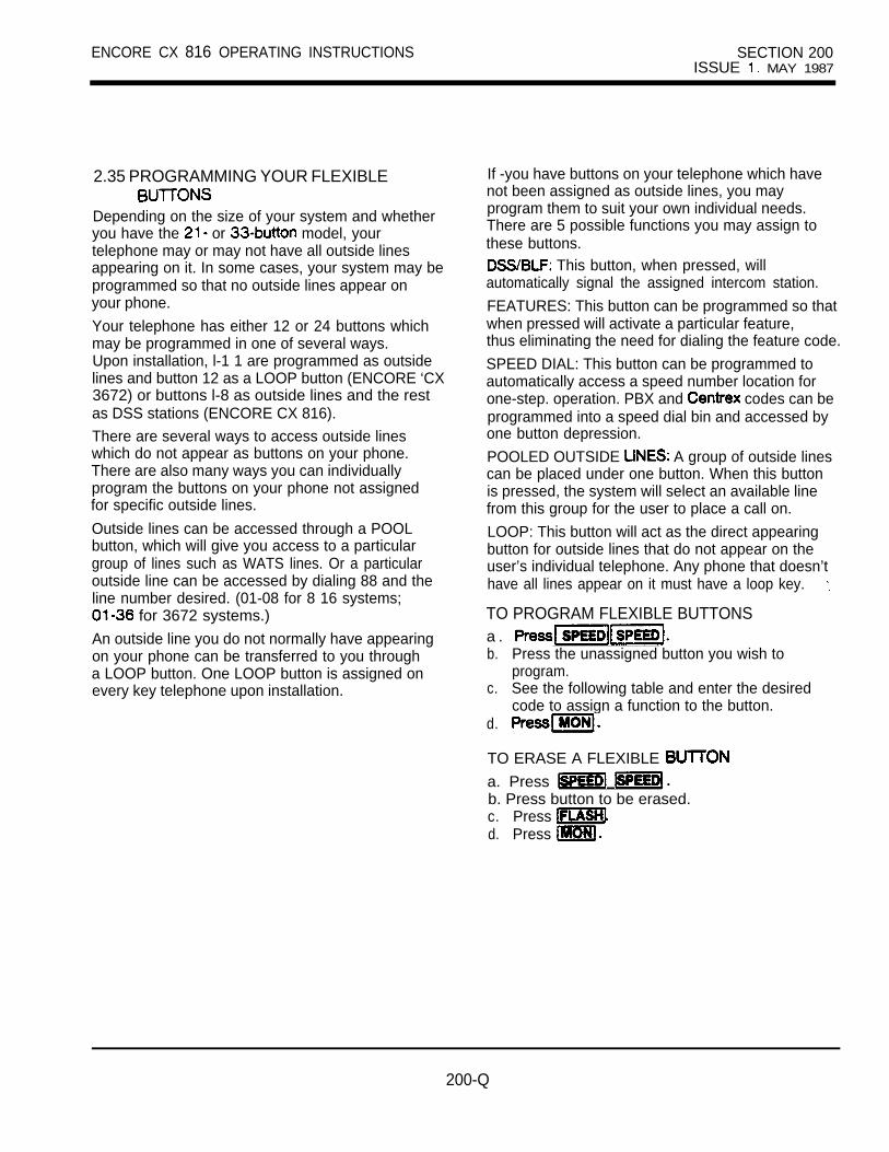
ENCORE CX 816 OPERATING INSTRUCTIONS SECTION 200ISSUE MAY 1987
2.35 PROGRAMMING YOUR FLEXIBLE
Depending on the size of your system and whetheryou have the or model, yourtelephone may or may not have all outside linesappearing on it. In some cases, your system may beprogrammed so that no outside lines appear onyour phone.
Your telephone has either 12 or 24 buttons whichmay be programmed in one of several ways.Upon installation, l-1 1 are programmed as outsidelines and button 12 as a LOOP button (ENCORE ‘CX3672) or buttons l-8 as outside lines and the restas DSS stations (ENCORE CX 816).
There are several ways to access outside lineswhich do not appear as buttons on your phone.There are also many ways you can individuallyprogram the buttons on your phone not assignedfor specific outside lines.
Outside lines can be accessed through a POOLbutton, which will give you access to a particulargroup of lines such as WATS lines. Or a particularoutside line can be accessed by dialing 88 and theline number desired. (01-08 for 8 16 systems;
for 3672 systems.)
An outside line you do not normally have appearingon your phone can be transferred to you througha LOOP button. One LOOP button is assigned onevery key telephone upon installation.
If -you have buttons on your telephone which havenot been assigned as outside lines, you mayprogram them to suit your own individual needs.There are 5 possible functions you may assign tothese buttons.
This button, when pressed, willautomatically signal the assigned intercom station.
FEATURES: This button can be programmed so thatwhen pressed will activate a particular feature,thus eliminating the need for dialing the feature code.
SPEED DIAL: This button can be programmed toautomatically access a speed number location forone-step. operation. PBX and codes can beprogrammed into a speed dial bin and accessed byone button depression.
POOLED OUTSIDE A group of outside linescan be placed under one button. When this buttonis pressed, the system will select an available linefrom this group for the user to place a call on.
LOOP: This button will act as the direct appearingbutton for outside lines that do not appear on theuser’s individual telephone. Any phone that doesn’thave all lines appear on it must have a loop key.
TO PROGRAM FLEXIBLE BUTTONSa . b. Press the unassigned button you wish to
program.c. See the following table and enter the desired
code to assign a function to the button.d.
TO ERASE A FLEXIBLE
a. Press b. Press button to be erased.c. Press d. Press
200-Q
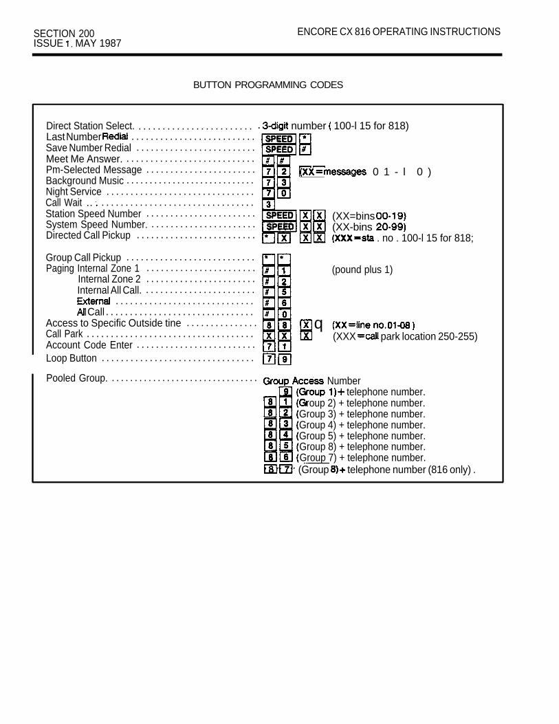
SECTION 200 ENCORE CX 816 OPERATING INSTRUCTIONSISSUE MAY 1987
BUTTON PROGRAMMING CODES
Direct Station Select. . . . . . . . . . . . . . . . . . . . . . . . . number 100-l 15 for 818)Last Number . . . . . . . . . . . . . . . . . . . . . . . . . .Save Number Redial . . . . . . . . . . . . . . . . . . . . . . . . .Meet Me Answer. . . . . . . . . . . . . . . . . . . . . . . . . . . .Pm-Selected Message . . . . . . . . . . . . . . . . . . . . . . .Background Music
0 1 - l 0 ). . . . . . . . . . . . . . . . . . . . . . . . . . . .
Night Service . . . . . . . . . . . . . . . . . . . . . . . . . . . . . . .Call Wait .. . . . . . . . . . . . . . . . . . . . . . . . . . . . . . . . .Station Speed Number . . . . . . . . . . . . . . . . . . . . . . .System Speed Number.
(XX=bins . . . . . . . . . . . . . . . . . . . . . .
Directed Call Pickup(XX-bins
. . . . . . . . . . . . . . . . . . . . . . . . . . no . 100-l 15 for 818;
Group Call Pickup . . . . . . . . . . . . . . . . . . . . . . . . . . .Paging Internal Zone 1 . . . . . . . . . . . . . . . . . . . . . . .
Internal Zone 2(pound plus 1)
. . . . . . . . . . . . . . . . . . . . . . .Internal All Call. . . . . . . . . . . . . . . . . . . . . . . .
. . . . . . . . . . . . . . . . . . . . . . . . . . . . . Call . . . . . . . . . . . . . . . . . . . . . . . . . . . . . . .
Access to Specific Outside tine . . . . . . . . . . . . . . .Call Park
q . . . . . . . . . . . . . . . . . . . . . . . . . . . . . . . . . . .
Account Code Enter(XXX park location 250-255)
. . . . . . . . . . . . . . . . . . . . . . . . .Loop Button . . . . . . . . . . . . . . . . . . . . . . . . . . . . . . . .
Pooled Group. . . . . . . . . . . . . . . . . . . . . . . . . . . . . . . . . Number telephone number.
roup 2) + telephone number.Group 3) + telephone number.Group 4) + telephone number.Group 5) + telephone number.Group 8) + telephone number.Group 7) + telephone number.(Group telephone number (816 only) .
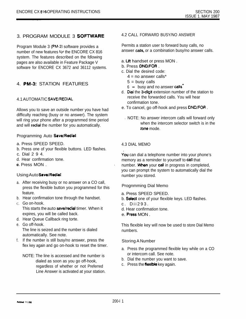
ENCORE CX OPERATING INSTRUCTIONS SECTION 200ISSUE 1. MAY 1987
3. PROGRAM MODULE 3
Program Module 3 software provides anumber of new features the ENCORE CX 816system. The features described on the fdlowingpages are also available in Feature Package Vsoftware for ENCORE CX 3672 and 36112 systems.
4. STATION FEATURES
4.1 AUTOMATIC
Allows you to save an outside number you have haddifficulty reaching (busy or no answer). The systemwill ring your phone after a programmed time periodand will the number for you automatically.
Programming Auto
a. Press SPEED SPEED.b. Press one of your flexible buttons. LED flashes.c. Dial 2 9 4.d. Hear confirmation tone.
Press MON .
Using Auto
a. After receiving busy or no answer on a CO call,press the flexible button you programmed for thisfeature.
b. Hear confirmation tone through the handset.C. Go on-hook.
d.e.
This starts the auto timer. When itexpires, you will be called back.Hear Queue Callback ring torte.Go off-hook.
f.
The line is seized and the number is dialedautomatically. See note.If the number is still busy/no answer, press theflex key again and go on-hook to reset the timer.
NOTE: The line is accessed and the number isdialed as soon as you go off-hook,regardless of whether or not PreferredLine Answer is activated at your station.
4.2 CALL FORWARD BUSY/NO ANSWER
Permits a station user to forward busy calls, noanswer or a combination busy/no answer calls.
a. handset or press MON .b. Press .c. Dial the desired code:
4 = no answer calls*5 = busy calls6 busy and no answer
d. the extension number of the station toreceive the forwarded calls. You will hearconfirmation tone.
e. To cancel, go off-hook and press .
l NOTE: No answer intercom calls will forward onlywhen the intercom selector switch is in the
mode.
4.3 DIAL MEMO
can dial a telephone number into your phone’smemory as a reminder to yourself to thatnumber. your in progress in completed,you can prompt the system to automatically dial thenumber you stored.
Prognmming Dial Memo
a. Press SPEED SPEED.b. one of your flexible keys. LED flashes.c . D i i 2 9 3 .d. Hear confirmation tone.e. MON .
This flexible key will now be used to store Dial Memonumbers.
Storing A Number
a. Press the programmed flexible key while on a COor intercom call. See note.
b. Dial the number you want to save.c. Press the key again.
200-l 1

SECTION 200 ENCORE CX 816 OPERATING INSTRUCTIONS
4.3 DIAL MEMO (CONT’D.)
NOTE: The first depression of the flexible keymutes the DTMF tones, so the party towhom you are speaking will not hearthem. The second depression restoresDTMF capability.
Checking The, Stored Number
a. Press the flexible key while on-hook.b. The display shows the number stored in the
. Memo bin, but does not dial ft.c. Press MON to cancel.
Dialing The Stored Number
a. Select a CO line.b. Press SPEED.c. Dial # .
or
a. Press SPEED.b. Dial The stored number is dialed automatically for you.
Cancelling The Number
a. Go off-hook and access a CO line.b. Press SPEED SPEED .c. Hang up.
4.4 FLASH ON INTERCOM CALLS
Disconnects a page or intercom call in progress andreturns intercom tone.
a. While connected to an intercom or page call, pressFLASH button.
b. Intercom dial tone Is returned.
4.5 INTERCOM CALL HOLD
You can program a flex button to allow an intercomcall to be put on hold.
a. Press SPEED SPEED.b. Press a flexible button. LED flashes.c. Dial 7 6.d. Hear confirmation tone.e. Press MON.
Placing An Intercom Call On Hold
a. Press HOLD button while on an Intercom call.The flex key flashes at the exclusive hold rate.
b. Press the flashing flexible button to retrieve the call.
An intercom call on hold will recall your station afterthe exclusive hold recall timer expires. The recall willsound like a tone ringing intercom call.
4.6 ONE-TIME DO NOT DISTURB (DND)
Allows you to prevent calls from ringing at yourstation while you’re on a call. The One-Time DNDcondition will automatically cancel when you endyour call.
a. Press the button while you’re off-hookand connected to a CO line or internal call.The button lights and off-hook tones atyour station are cancelled.
b. To cancel, simply go on-hook. LED extinguishes and DND cancels.
NOTE: If the button Is pressed whileon-hook, DND is activated and mustbe cancelled by pressing the button again while on-hook.
4.7 PROGRAMMING CODE 72 ON A FLEX KEY
You can program code 72 on a flexible key to speed of messages.
a Press SPEED SPEED .b. Press the desired flex key. LED flashes.c. Dial 7 2 .d. Hear confirmation tone.e. Press MON .

ENCORE CX 816 OPERATING INS I I I 3, NOVEMBER
4.7 PROGRAMMING CODE 72 ON A FLEX KEY(CONT’D.)
Leaving A Message
Press the flex key you programmed.Dial the code for the desired message 0).
C. Hear confirmation tone.
a
Press the flex key you programmed.Dial 0 0.
c. Hear confirmation tone.
5. PM-3: ATTENDANT FEATURES
5.1 DISABLING OUTGOING ACCESS
The attendant station can disable CO lines, prevent-ing outgoing CO calls.
Lii handset or press MON.Dial 2 9 8.Hear confirmation tone.Depress the line button of the CO to be disabled.
e. You will hear confirmation tone and see the COindicator flashing.
f. To re-activate the CO line, repeat the steps fol-lowed to disable it.
5.2 SELECTING BACKGROUND MUSIC AT ANINTERCOM PHONE BOX
Lii the handset or MON.Dial 2 9 7.
C. Dial the station number of the phone box(or press the DSS key, if programmed).
d.
1 channel 1Hear confirmation tone and hang up.
NOTE: Only the attendant station has this
6.
6.1
a.
b.
7.
7.1
PM-3: PHONE BOX FEATURES
BLOCKING BACKGROUND MUSIC
Press the button while receiving back-ground music. Music is cancelled.Press again to return backgroundmusic.
FEATURES
SPEAKERPHONE
Speakerphone activation is automatic when pressingan outside CO Line, POOL, DSS, programmedFlexible button, or dialing any dial code. Using theSpeakerphone without a MON button programmedon a flexible button is allowed, but requires you tolift and replace the handset to terminate the call.
7.2 PLACING AN OUTSIDE CALL
With a programmed MON button
a. Press desired CO line button or dial pooledgroup access code.
b. Dial telephone number.C. Press MON button to terminate call.
(or with no MON button programmed)
C. Lift and replace handset to terminate call.
7.3 ANSWERING AN OUTSIDE CALL
a programmed MON button
a.
b.
b.
Press CO line or LOOP button withincoming call.Press MON button to terminate call.
(or with no MON button programmed)
and replace handset to terminate call.
200-l 3

SECTION 200 ENCORE CX 816 OPERATING INSTRUCTIONSISSUE 3, NOVEMBER 1989
7.4 PLACING AN INTERCOM CALL
With a programmed MON button
a. Press programmed DSS button or dial stationextension number.
b. Press MON button to terminate call.
(or no MON button programmed)
b. Lii and replace handset to terminate call.
7.5 ANSWERING AN INTERCOM CALL
With a programmed MON button
Call In Tone Rlnglng Mode
Press MON button to answer.Press MON button to terminate call.
(or with no MON button programmed)
Lii handset to answer.Replace handset to terminate call.
Recelvlng Call In
a. Upon hearing Intercom announce tone, speakin a normal voice.
b. Call is automatically terminated when callerhangs up.
Note: Call connection is indicated by the illuminatedcondition of the LED for the programmedMON button. There is no visual call connec-tion indication if the feature code not assigned to a button.
7.6 MUTE BUTTON
If a flexible button has been programmed with theMUTE programming code, it can be used provideprivacy during speakerphone or handset operation bymuting the microphone.
a. Press MUTE button to activate (LED willilluminate steady).
b. Press MUTE button again to de-activate (LED willgo off).
7.7 CONFERENCE
A Conference button can be programmed on aflexible button to allow the same method of con-ference as on the full-sized key telephones. How-ever, an abbreviated method of add-on conferencecan be performed using the TRANS button on the Button Enhanced Key Telephone. A conference with outside and 2 Internal parties can be established.
The outside call must be established first. Also, thereare many different options available for the con-ference feature. Only the methods marked willoperate on your telephone.
There are two basic types of conferences:
ADD ON 1 outside party with up to 4 inside parties.
MULTI-LINE 2 outside parties with inside party.
Establlshlng a Three-way Add On ConferenceWithout a programmed CONF button
Receive or make an outside call.Press the TRANS button (hear IC dial tone).
C. Dial the station to add to the conference.if station user answers:
d. Press the TRANS button (conference alert toneis heard and all are connected).
or station user Is not available
Press the TRANS button (you’re reconnected toyour caller).Hang up to exit conference in progress.
Note: to the conference is not allowed.
200-l 4
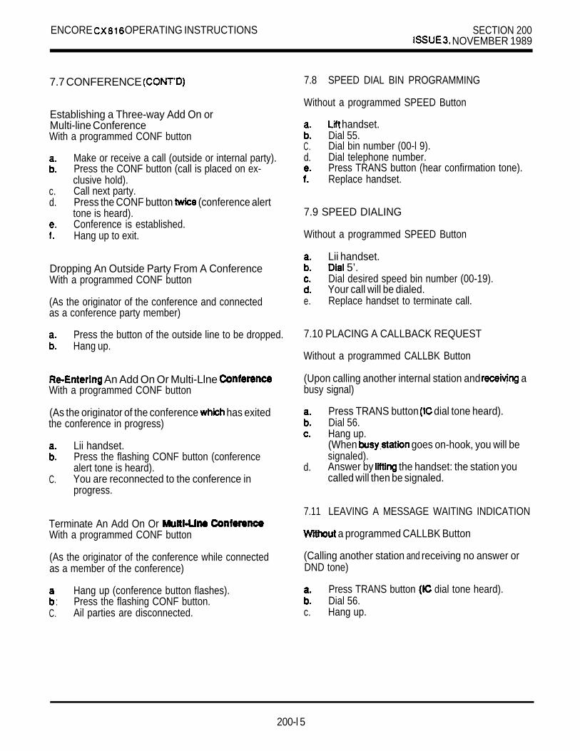
ENCORE OPERATING INSTRUCTIONS SECTION 200 NOVEMBER 1989
7.7 CONFERENCE
Establishing a Three-way Add On orMulti-line ConferenceWith a programmed CONF button
Make or receive a call (outside or internal party).Press the CONF button (call is placed on ex-clusive hold).
c. Call next party.d. Press the CONF button (conference alert
tone is heard).Conference is established.Hang up to exit.
Dropping An Outside Party From A ConferenceWith a programmed CONF button
(As the originator of the conference and connectedas a conference party member)
Press the button of the outside line to be dropped.Hang up.
An Add On Or Multi-Llne With a programmed CONF button
(As the originator of the conference has exitedthe conference in progress)
Lii handset.Press the flashing CONF button (conferencealert tone is heard).
C. You are reconnected to the conference inprogress.
Terminate An Add On Or With a programmed CONF button
(As the originator of the conference while connectedas a member of the conference)
:Hang up (conference button flashes).Press the flashing CONF button.
C. Ail parties are disconnected.
7.8 SPEED DIAL BIN PROGRAMMING
Without a programmed SPEED Button
handset.Dial 55.
C. Dial bin number (00-l 9).d. Dial telephone number.
Press TRANS button (hear confirmation tone).Replace handset.
7.9 SPEED DIALING
Without a programmed SPEED Button
Lii handset. 5’.
Dial desired speed bin number (00-19).Your call will be dialed.
e. Replace handset to terminate call.
7.10 PLACING A CALLBACK REQUEST
Without a programmed CALLBK Button
(Upon calling another internal station and abusy signal)
Press TRANS button dial tone heard).Dial 56.Hang up.(When goes on-hook, you will besignaled).
d. Answer by the handset: the station youcalled will then be signaled.
7.11 LEAVING A MESSAGE WAITING INDICATION
a programmed CALLBK Button
(Calling another station and receiving no answer orDND tone)
Press TRANS button dial tone heard).Dial 56.
c. Hang up.
200-l 5

SECTION 200 ENCORE CX 816 OPERATING INSTRUCTIONSISSUE 3, NOVEMBER 1989
7.12 LEAVING A MESSAGE WAITING INDICATION
a programmed CALLBK Button
(Calling another station and receiving no answer orDND tone)
a. Press programmed CALLBK (hear confirmationtone).
b. Hang up.
7.13 ANSWERING A MESSAGE WAITINGINDICATION
Without a Programmed CALLBK Button
Lii handset.Dial 57 (the station that left the message will besignalled).
7.14 ANSWERING A MESSAGE WAITINGINDICATION
With a Programmed CALLBK Button
handset.Press the Programmed CALLBK button.(The station that left the message will be nalled).
7.15 CALL FORWARDING
Without a programmed Button
:Lii handset.Dial 54 + (optional codes or
c. Dial destination number where your are to forwarded (hear tone).
d. Hang up.
7.16 CALL FORWARDING
Without a Programmed Button
(To Remove Call Forward Without a programmed Button)
handset.Dial 54 (hear confirmation tone).
c. Hang up.
7.17 USING DO NOT DISTURB
Without a
Lift handset.Dial 53 (hear confirmation tone).
C. Hang up.
To Remove
handset.Dial 53 (hear confirmation tone).
C. Hang up.
7.16 HOOK FLASH ON OUTSIDE CALL
Without a programmed FLASH Button
(While on a CO line)
Press TRANS button (IC dial tone is heard).Dial 51.A FLASH signal is sent to the CO line.You’re to the CO line.
7.19 QUEUING
Without a Callback Button
Press line button (hear busy tone).Press TRANS button (hear IC dial tone).
c. Dial 56 (hear confirmation tone MGS LED il-luminates steady).
d. Hang up.
7.20 ANSWERING A QUEUE CALLBACK
Without Callback Button
(Hear ringing and CO line button LED flashes at fastrate)
a. Press flashing CO line button (you are connectedto line).
b. MSG LED will extinguish.
200-l 6

ENCORE OPERATING INSTRUCTIONS SECTION 200 3, NOVEMBER 1989
7.21 PROGRAMMING A FLEXIBLE BUT-TON
Without SPEED button
Lift handset.Dial 6’.
C. Press flex button to be programmed (flex buttonwill flash).
d. Dial code for desired feature (see Table A).Hear confirmation tone.Hang up.
7.22 ERASING A PROGRAMMED FLEXIBLEBUTTON
Without Speed button
Lift handset.Dial
c. Press flex button to be erased (flex button willflash).
d. Dial code 51.
Hear confirmation tone.Hang up.
7.23 RING CONTROL
The set does not have an intercom modeselector switch like the full-sized key telephones. Indefautt, intercom calls placed to the set will be .received in the handsfree mode. By dialing a code,you can switch between to the tone ing mode and versa. A flexible button can alsobe programmed to function for this feature.
(To Toggle Between Handsfree And Tone RingingMode)
a. Dial 699 (steady tone is heard and is in toneringing mode).
b. Dial 699 (ICM announce tone is heard and set isin handsf mode).
7.24 NUMBER
Without a programmed SPEED button
The last number dialed on an outside line is saved.To redial the number:
Lii handset.Dial 5”.
8. TRANSFER RECOVERY
8.1 TRANSFERRING CALLS
While connected to an outside call:
Press the TRANS button (hear dial tone).Dial the station number or press the DSS buttonfor the transfer destination.
Receiving set busy, in DND or no answer in Tonemode:
Press TRANS button (you are tocall staged for transfer).
or call is answered:
Make transfer announcement.Hang up (call is transferred).
200-l 7

ENCORE CX 3672KEY TELEPHONE SYSTEM
SECTION ISSUE MAY 1987
ENCORE CX 3672 OPERATING INSTRUCTIONS
TABLE OF CONTENTS
PAGE1. . . . . . . . . . . . . . . . . . . . . . . . . . . . . . . . . . . . . . . . . . . . . . . . . . . . . . . . . .
2 ADDITIONAL 3672 KEY TELEPHONE FEATURES2.1 OFF-HOOK VOICE ANNOUNCE. . . . . . . . . . . . . . . . . . . . . . . . . . . . . . . . . . . . . . . 12.2 PAGING. . . . . . . . . . . . . . . . . . . . . . . . . . . . . . . . . . . . . . . . . . . . . . . . . . . . . . . . . . . . 12.3 CONFERENCE . . . . . . . . . . . . . . . . . . . . . . . . . . . . . . . . . . . . . . . . . . . . . . . . . . . . . 12.4 BACKGROUND MUSIC . . . . . . . . . . . . . . . . . . . . . . . . . . . . . . . . . . . . . . . . . . . . . . 12.5 PROGRAMMING YOUR FLEXIBLE . . . . . . . . . . . . . . . . . . . . . . . . . . . 22.6 LEAST COST ROUTING . . . . . . . . . . . . . . . . . . . . . . . . . . . . . . . . . . . . . . . . . . . . . 2
3. SINGLE LINE TELEPHONE FEATURES3.1 PLACING AN INTERCOM CALL . . . . . . . . . . . . . . . . . . . . . . . . . . . . . . . . . . . . . . . 23.2 PLACING AN OUTSIDE CALL . . . . . . . . . . . . . . . . . . . . . . . . . . . . . . . . . . . . . . . . .3.3 CALL PARK
: : : : : : : : : :. . . . . . . . . . . . . . . . . . . . . . . . . . . . . . . .
3.4 UNSCREENED TRANSFER . . . . . . . . . . . . . . . . . . . . . . . . . . . . . . . . .3.5 SCREENED TRANSFER. . . . . . . . . . . . . . . . . . . . . . . . . . . . . . . . . . . . . . . . . . . . . .3.6 GROUP PICKUP. . . . . . . . . . . . . . . . . . . . . . . . . . . . . . . . . . . . . . . . . . . . . . . 23.7 DIRECTED CALL PICKUP . . . . . . . . . . . . . . . . . . . . . . . . . . . . . . . . . . . . . . . . . . . . . 23.8 CALL FORWARD . . . . . . . . . . . . . . . . . . . . . . . . . . . . . . . . . . . . . . . . . . . . . . . . . . . . 23.9 TO REMOVE CALL FORWARD. . . . . . . . . . . . . . . . . . . . . . . . . . . . . . . . . . . . . . . . 23.10 . . . . . . . . . . . . . . . . . . . . . . . . . . . . . . . . . . . . . . . . . . . . . . . . . . 23.11 . . . . . . . . . . . . . . . . . . . . . . . . . . . . . . . . . . . . . . . . . . . . . . . . . 33.12 STORING SPEED NUMBERS . . . . . . . . . . . . . . . . . . . . . . . . . . . . . . . . . 33.13 . . . . . . . . . . . . . . . . . . . . . . . . . . . . . . . . . . . . . . . . . . . . . . 33.14 A CALL . . . . . . . . . . . . . . . . . . . . . . . . . . . . . . . . . . . . . . . . . 33.15 A MESSAGE INDICATION . . . . . . . . . . . . . . . . . . . . . . . . . . . .3.16 . . . . . . . . . . . . . . . . . . . . . .3.17 QUEUING . . . . . . . . . . . . . . . . . . . . . . . . . . . . . . . . . . . . . . . . . . . . . . . . . . . . . . . . . .3.18 PAGING. . . . . . . . . . . . . . . . . . . . . . . . . . . . . . . . . . . . . . . . . . . . . . . . . . . . . . . . . . . .3.19 CONFERENCE. . . . . . . . . . . . . . . . . . . . . . . . . . . . . . . . . . . . . . . . . . . . . . . . . . . . . . 43.20 UNIVERSAL ANSWER . . . . . . . . . . . . . . . . . . . . . . . . . . . . . . . . . . . . . . . . . 4
4. WITH CONSOLE4.1 PAGING . . . . . . . . . . . . . . . . . . . . . . . . . . . . . . . . . . . . . . . . . . . . . . . . . . . . . . . . . . . . 44.2 CALL PARK. . . . . . . . . . . . . . . . . . . . . . . . . . . . . . . . . . . . . . . . . . . . . . . . . . . . . . . . . 44.3 HUNT GROUPS . . . . . . . . . . . . . . . . . . . . . . . . . . . . . . . . . . . . . . . . . . . . . . . . . . . . . 44.4 OVERRIDE . . . . . . . . . . . . . . . . . . . . . . . . . . . . . . . . . . . . . . . . . . . . . . . . . . . . . . . . . 44.5 CALL WAIT . . . . . . . . . . . . . . . . . . . . . . . . . . . . . . . . . . . . . . . . . . . . . . . . . . . . . . . . . 44.6 NIGHT SERVICE . . . . . . . . . . . . . . . . . . . . . . . . . . . . . . . . . . . . . . . . . . . . . . . . . . . . 4
5. DIRECT INWARD . . . . . . . . . . . . . . . . . . . . . . . . . . . . . . . . . . .
201 -A

SECTION 201 ENCORE CX 3672 OPERATING INSTRUCTIONSISSUE 2. NOVEMBER 1989
TABLE OF CONTENTS (CONT’D.)
DESCRIPTION PAGE
6. FEATURE PACKAGE V . . . . . . . . . . . . . . . . . . . . . . . . . . . . . . . . . . . . . . . . . .
7. STATION FEATURES 7.1 AUTOMATIC HOLD . . . . . . . . . . . . . . . . . . . . . . . . . . . . . . . . . . . . . . . . . . . . . 5
CALL FORWARD OFF PREMISES . . . . . . . . . . . . . . . . . . . . . . . . . . . . . .CUSTOM MESSAGES . . . . . . . . . . . . . . . . . . . . . . . . . . . . . . . . . . . . . . . . . .DIRECTED CALL PICKUP OF A PHONE BOX . . . . . . . . . . . . . . . . . . . . . .DISPLAY SECURITY . . . . . . . . . . . . . . . . . . . . . . . . . . . . . . . . . . . . . . . . . . . .FORWARDING CALLS TO UCD, HUNT AND VOICE MAIL GROUPS . . . . .
7.7 PROGRAMMING YOUR NAME INTO DISPLAY . . . . . . . . . . . . . . . . . . . . .7.8 TRUNK GROUP ACCESS ON CALLS . . . . . . . . . . . . . . . . . . . . . . . .7.9 UCD AGENT IN/OUT. . . . . . . . . . . . . . . . . . . . . . . . . . . . . . . . . . . . . . . . . . . . 6
8. FEATURES (FP5)8.1 CUSTOM MESSAGES . . . . . . . . . . . . . . . . . . . . . . . . . . . . . . . . . . . . . . . . .8.2 DISABLING OUTGOING ACCESS . . . . . . . . . . . . . . . . . . . . . . . . . . . . . . . . .8.3 FORWARDING INCOMING CO CALLS OFF-PREMISE . . . . . . . . . . . . . . .8.4 SELECTING BGM AT A PHONE BOX . . . . . . . . . . . . . . . . . . . . . . . . . . . . .
9. SLT FEATURES (FP5)9.1 ACCOUNT CODES . . . . . . . . . . . . . . . . . . . . . . . . . . . . . . . . . . . . . . . . . . . . .9.2 CALL FORWARD BUSY/NO ANSWER . . . . . . . . . . . . . . . . . . . . . . . . . . . .9.3 CALL FORWARD OFF PREMISE . . . . . . . . . . . . . . . . . . . . . . . . . . .....9.4 PROGRAMMING YOUR NAME . . . . . . . . . . . . . . . . . . . . . . . . . . . . . . . . . . .9.5 UCD AGENT . . . . . . . . . . . . . . . . . . . . . . . . . . . . . . . . . . . . . . . . . . . . 8
10. FEATURE PACKAGE VI (FP5) SOFTWARE . . . . . . . . . . . . . . . . . . . . . . . . . . . . . . . . 9
11. STATION FEATURES (FP5) . . . . . . . . . . . . . . . . . . . . . . . . . . . . . . . . . . . . . . . . . . . . .11.1 DISPLAY CALLS IN QUEUE FOR UCD GROUPS . . . . . . . . . . . . . . . . . . . . .11.2 INTERCOM TRANSFER . . . . . . . . . . . . . . . . . . . . . . . . . . . . . . . . . . . . . . . . .11.3 FORCED TONE RINGING INTERCOM CALL11.4 SLT PERSONAL . . . . . . . . . . . . . . . . . . . . . . . . . . . . . . . . . . . . . . . . . 1011.5 SLT MULTI-LINE CONFERENCE . . . . . . . . . . . . . . . . . . . . . . . . . . . . . . . . . 10
OF FIGURES
1. PATTERN LCD DISPLAY . . . . . . . . . . . . . . . . . . . . . . . . . . . . . . . . . . . . . . . . . . . 6

ENCORE CX 3672 SECTION 201KEY TELEPHONE SYSTEM ISSUE MAY 1987
ENCORE CX 3672 OPERATING INSTRUCTIONS
1. INTRODUCTION
The ENCORE CX 3672 system has access to allfeatures available to the ENCORE CX 816 sys-tem (except alarm) and all features operate thesame way. In addition, the 3672 system has ac-cess to a number of other advanced featuresand can use Single Line Telephones and DirectStation/Line Selector units.
2. ADDITIONAL 3672 CAPACITIES
2.1 OFF-HOOK VOICE ANNOUNCE (OHVA)a. If your telephone has been programmed for
off-hook voice announce and you are alreadytalking on a call, another station using the CALLWAIT feature to notify you of a waiting callwill result in a warning tone and an immediatevoice cut-through to your speaker.
NOTE: If you are using your speakerphone,monitoring a call through yourspeakerphone or are in DND,the standard CALL WAIT signal of mutedringing will result.The called station must be programmedfor OHVA for this feature to work.A user can disable OHVA by placinghis/her telephone in the TN answeringmode. However, the attendant csn voiceannounce off-hook to an OHVAtelephone set to TN by using theOVERRIDE button.
2.2 PAGINGPaging in the 3872 system functions the same as inthe 816 system. 3672, however, access to3 additional zones:
Additional Page External Zone 2 7Internal Zone 3 3qInternal Zone 4 4
See Section 200, 816 Operating Instructions,paragraph 2.16 for detailed operating instructions forthe paging feature.
.
CONFERENCE
TYPES OF CONFERENCESa. Add-On: 5 internal parties, or 4 internal and
1 outside.b. Multi-Line: 1 internal and 2 outside.
ESTABLISHING A CONFERENCEa.b.
e.
internal or outside party. (button lights and party is placed
on exclusive hold).Call next Press -again.When all parties are on hold, press asecond time and conference is established.
EXITING A CONFERENCE (Initiator)a. Hang up.
RE-ENTERING A CONFERENCEa.b.
TO
C.
handset.Press
ADD CONFERENCEPress .
PARTIES
TO DROP OUTSIDE PARTYa. You must be actively in the conference.b. Press appropriate outside line.c. Hang up.
TERMINATING A CONFERENCE
2.4 BACKGROUND MUSICTwo music channels csn be connected to the3672 system.a Remain on-hook.b. or press preprogrammed feature
access button.c. If only one music channel is connected,
dialing or pressing the feature accessbutton a second time turns the music off.
201-l

SECTION 20 1ISSUE MAY 1987
ENCORE CX 3672 OPERATING INSTRUCTIONS
2.4 BACKGROUND MUSIC (CONT’D)d. If 2 music channels are connected, dialing
or pressing the feature access button a secondtime will access the second music channel.To remove music, dial or press the buttona third time.
2.5 PROGRAMMING YOUR FLEXIBLEBUTTONS
Your telephone has either 12 or 24 buttons whichmay be programmed in one of several ways.Upon installation, buttons l-1 1 are programmedas outside lines and button 12 as a loop button.See Section 200, 816 Operating Instructions,Paragraph 2.35 for details about programming your
flexible buttons.
2.6 LEAST COST ROUTINGa. h ndset.b. Dial (confirmation tone).
. c. Dial if required.d. Dial area code if required.e. Dial telephone number desired.
3. SINGLE LINE TELEPHONE FEATURES
3.1 PLACING AN INTERCOM CALLa. handset.b. Dal intercom number.
3.2 PLACING AN OUTSIDE CALLa. handset.b. appropriate group access code:
(9, 81, 82, 83, 84, 85, 86) 88 and desired line number to access a specific line.
c. Dial desired telephone number.
3.3 CALL PARK
a. While connected to an outside line, briefly pressand release
b. Dial one of the call park locations c. To retrieve a parked call, q and the desired
call park location
3.4 UNSCREENED TRANSFERa. Briefly press and release hookswitch.b. Dial desired intercom number.c. Hang up to complete transfer.
3.5 SCREENED TRANSFERa. press and release hookswitch.b. desired intercom number.c. Announce call.d. Hang up to complete transfer.
3.6 GROUP CALL PICKUPUpon hearing an unattended telephone in yourgroup ringing:a. Lift handset.b. Dial You will be connected to calling party.NOTE: Must be in the same pickup group.
intercom calls and transferred outsideline calls can be picked up.
3.7 DIRECTED PICKUPUpon hearing an unattended telephone ringing:a. handset.b. Dial c. Dial station number of ringing phone.You will be connected to calling party.
3.6 FORWARD
C.
d.
Lift handset.
Oiai station number where are to beforwarded.
3.9 TO REMOVE CALL FORWARDa handset.b. Dial c. Hang up.
3.10 DO NOT DISTURBa. Lift handset.b. c. up.d. Repeat to remove Not Disturb.

ENCORE CX 3672 OPERATING INSTRUCTIONS SECTION 20 ISSUE MAY 1987
3.11 USING SPEED DIALa. Lift handset.b . c. Dial desired speed number bin (00-99).
NOTE: You will not hear dial tone or digitsbeing dialed when using speed dial.
3.12 STORING STATION SPEED NUMBERSa.b.
e.
Lift handset.Dial Dial speed number bin (00-l 9).Dial telephone number you wish to store.Briefly press and release hookswitch.You will hear confirmation tone.
3.13 PLACING A CALL WAIT (CAMP-ON)You can signal an extension that is busy to alertthem to your call.a. After receiving intercom busy tone, briefly press
and release the hookswitch and The called station will receive 1 burst of ringing.
b. When the called party answers, consult withthem or hang up to transfer a call.
You can signal an extension that is busy to alert .them that you are attempting to transfer a CO linecall to them.a. After receiving intercom busy tone, briefly press
and release the hookswitch to return to yourCO line call.
b. After informing the calling party of the busyextension, briefly press and release thehookswitch again and dial to camp-on the call.
3.14 RECEIVING A CALL WAITa. Receive call watt warning tone through
handset.b. Choose desired call. (Hang up on present
and take new one or ignore the call wait signal.)
3.15 LEAVING A MESSAGE WAITINGINDICATION
If you dial a telephone that is unattended in DND,you can leave a message waiting indication.a. After receiving no answer, briefly press and
release hookswitch.b. Dial q m. You will hear confirmation tone.c. Hang up.
3.16 ANSWERING A MESSAGE WAITINGINDICATION
You see your message waiting light is lit:a. Lift handset.b .
The station that left the message will ring.
NOTE: Only Single Line Telephones equippedwith a Message Waiting lamp will haveaccess to this feature.
3.17 QUEUINGIf you find that a particular outside line is wish to be placed on a list waiting for a line in thatgrouo to become available:a.b.
Dial outside line access code.Receive busy tone.Briefly press and release hookswitch.Dial You will hear confirmation tone.
3.18 PAGINGa. handset.b. Dial desired page zone.
You will hear a warning tone. Deliver page in normal tone of voice.
d. Hang up to terminate page.
PAGE ZONES
internal Zone 1Internal Zone 2Internal Zone 3
1 2 3
Internal Zone 4 All Call
External Zone 1 2
System All Call
NOTE: Phones in DND will not receive pagingannouncements. When making anAll Call Page, the initiator will getbusy tone if any zone is busy.

SECTION 20 1 ENCORE CX 3672 OPERATING INSTRUCTIONSISSUE MAY
3.19 CONFERENCE(A single line telephone can be part of aconference consisting of one external andtwo internal stations.)
a, Place the outside call on hold by pressing andreleasing hookswitch.
b. Dial the station you wish to add to theconference.
c. When the internal station answers, briefly pressand release hookswitch again and all 3 partieswill be connected.
3.20 UNIVERSAL NIGHT ANSWER (UNA)a. Upon hearing an incoming signal, lift handset.b. Dial UNA access code c. You will be connected to ringing outside line.
4. ATTENDANT WITH CONSOLE
4.1 PAGINGa. Press desired (INT, EXT) button.
You will hear a warning tone.b. Speak in normal tone of voice to deliver
message.c. Hang up handset.
If you depress a paging key on the DSS consolewhile you are conversing on an outside line,the outside line will automatically be put on hold andyou can make your page announcement.
4.2 CALL PARK
a.
b.
e.
While connected to outside line, press desired button.At time you can page or call another internalstation. When the party you called responds:Announce call.Hang up, press or access anotheroutside line.To retrieve a parked call, q and the parklocation number (253, 254, 255).
4.3 HUNT GROUPS
a. While connected to an outside line,press HUNT group button.
b. Hang up, press access anotheroutside line.
c. Call will circulate among stations assigned to thathunt group.
4.4 OVERRIDE
a. Press button of station to be overridden.b. You will receive DND tone.c. Press The station will receive
ringing.
d. When that station presses their buttonor lifts the handset, you may converse.
The attendant can use Override on a key telephoneprogrammed with OHVA, but which has the switchset to TN, to make an off-hook voice announcement.
4.5 CALL WAIT (CAMP-ON)
a.
b.C.
While connected to an outside line, press thedesired station button.When busy tone is heard, press Hang up, access another line,or press
4.6 NIGHT SERVICEa. Attendant presses to activate and
deactivate night service.
5. DIRECT INWARD SYSTEM ACCESS (DISA)
5.1 SYSTEM ACCESS’
a. Dial the number assigned to a line. Thecall is answered by the system and system dial tone is heard.
b. Dial the access code. If valid, dial tone resumes.
*NOTE: Calls must be made from telephonessending DTMF dialing.
5.2 ACCESS OUTGOING TRUNKS AND DIALING
a. Dial 8 8 X X . (where XX outside linepositions
You will be connected to the line dialed and willhear new dial tone if the line is not busy.b. Dial the desired telephone number.
5.3 CALLING SYSTEM STATION USERS
a. Dial the desired station number.**If the station is not busy, the called stationreceives indication and ringing for the line.The caller hears tone until thecall attempt expires.
If the station is busy, you will hear system busytone for 5 seconds. Then dial tone Isrestored. Upon hearing new dial tone, youcan repeat the steps in 5.2 or 5.3.
**NOTE: The station dialed must have a lineappearance of the line or a Loopbutton assigned.
201-4

ENCORE CX 3672 OPERATING INSTRUCTIONS SECTION ISSUE MAY 1 9 8 7
6. FEATURE PACKAGE V (FP6)
The following additional features are provided byFeature Package V software. Feature Package V alsoprovides all the features available in Program Module3 200 for
7. FEATURES (FP5)
7.1 AUTOMATIC HOLD
You can put one CO call on hold by selecting asecond CO line.
a. You are talking to an outside patty.b. Press a second CO line to make or answer another
outside call.The first outside party is put on hold automatically.
c. To cancel a call, hang up. Other calls on willremain on hold.
7.2 CALL FORWARD OFF PREMISE
Allows you to forward intercom and transferred COcalls to an off-premise location.
Forwarding Calls Off
a.b.
f.
the handset or press MON .Press .Press SPEED button.Dial the bln (01 the phone number Hear confirmation tone.To cancel, go off hook and
NOTE: The forward destination must program-med under a bin for featureto possible.
7.3 CUSTOM MESSAGES
You can leave a message so that anyone with adisplay telephone can it call you.
a. Dial 7 2.b. Dial the number of the message (1 l-20).
Ask the attendant for a list of available c. Press MON . The message is now programmed
on your phone.d. 7 2 0 0 to a
flashing button twice while on-hook.
7.4 DIRECTED CALL PICKUP OF AN INTERCOMPHONE BOX
Allows you to pick up an intercom call terminated at aphone box.
a. You hear a handsfree call at an intercom phone box.b. Dial l .c. Dial the extension number of the phone box.d. Speak to calling party.
7.5 DISPLAY SECURITY
Allows a station user to program a that not on LCD
display when dialed.
Storing
a. Press SPEED SPEED.b. Dial the desired bin number.c. button.d. Dial the to kept prlvate.8. Press SPEED.
g.
NOTE: Depressing the button as the firstentry blanks from display dlgii that follow.
Accessing
a. SPEED.b. Dial bin number.
The system dial the number. The display willshow “DISPLAY SECURITY’.
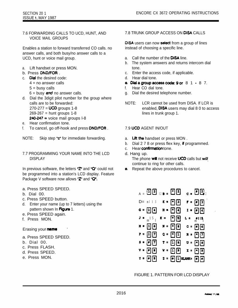
SECTION 20 1 ENCORE CX 3672 OPERATING INSTRUCTIONSISSUE MAY 1987
7.6 FORWARDING CALLS TO UCD, HUNT, ANDVOICE MAIL GROUPS
Enables a station to forward transferred CO calls. noanswer calls, and both busy/no answer calls to aUCD, hunt or voice mail group.
a. Lift handset or press MON.b. Press .c. the desired code:
4 = no answer calls5 = busy calls6 = busy no answer calls.
d. Dial the 3digit pilot number for the group wherecalls are to be forwarded:270-277 = groups 1-8269-267 = hunt groups 1-8
voice mail groups l-8e. Hear confirmation tone.f. To cancel, go off-hook and press .
NOTE: Skip step for immediate forwarding.
7.7 PROGRAMMING YOUR NAME INTO THE LCDDISPLAY
In previous software, the letters and could notbe programmed into a station’s LCD display. FeaturePackage V software now allows and
a. Press SPEED SPEED.b. Dial 00.c. Press SPEED button.d. Enter your name (up to 7 letters) using the
pattern shown In 1.e. Press SPEED again.f. Press MON.
Erasing your
a. Press SPEED SPEED.b. Dial 00.c. Press FLASH.d. Press SPEED.e. Press MON.
7.8 TRUNK GROUP ACCESS ON CALLS
users can now from a group of linesinstead of choosing a specific line.
a. Call the number of the line.b. The system answers and returns intercom dial
tone.c. Enter the access code, if applicable.d. Hear dial tone.
8 1 8 7.f. Hear CO dial tone.g. Dial the desired telephone number.
NOTE: LCR cannot be used from DISA. If LCR isenabled, users may dial 8 0 to accesslines in trunk group 1.
7.9 AGENT IN/OUT
a. handset or press MON .b. Dial 2 7 8 or press flex key, programmed.c. Hear tone.d. Hang up.
The phone not receive calls but continue to ring for other calls.Repeat the above procedures to cancel.
A = 1 2 l 2 2
D= m l 1 3
1 5 l m l m l
FIGURE 1. PATTERN FOR LCD DISPLAY
2016

ENCORE CX 3672 OPERATING INSTRUCTIONS SECTION 2 0 1
8. FEATURES (FP5)
8 . 1 CUSTOM MESSAGES
Up to 10 custom messages can be programmed bythe first attendant station.
a. Dial 29 2.b. H e a r confirmation tone.c. You will see this display:
NOTE: CO access codes include:9 Group 1 CO lines
80 Group 1 CO lines8 1 Group 2 CO lines82 Group 3 CO lines83 Group 4 CO lines84 Group 5 CO lines
Group 6 CO lines86 Group 7 CO lines
co line, xx 89 co lines
d. Dial the bin number ( 1 l - 2 0 ) .e. Enter the desired message, via the pad,
using the pattern shown in Figure 1.Press HOLD . Hear confirmation tone.
NOTE: Custom messages may be up to 2 4characters in length.
8.2 OUTGOING ACCESS
The first attendant station can disable CO lines,preventing outgoing CO calls. See 200.
8.3 FORWARDING INCOMING CO CALLS PREMISE
Call Off Premises
a.b.
8 . 4
a .b.
C.
d.
Dial 2 9 6. the CO access code.
Dial .Hear confirmation tone.
SELECTING BACKGROUND MUSIC AT ANINTERCOM PHONE BOX
2 9 7. the station number of the phone box (or
the DSS key, if programmed).0, 1 or 2 .
1 1
Hear confirmation tone and hang up.
NOTE: attendant station 1
the first attendant to incoming caiis to an off-premise location.
9. SLT FEATURES (FP5)Storing Numbers
in a speed bin, store the number of the where caiis are to be forwarded. provided for storing speed
Forwarding Calls Account Cod. Call
a. Diai 2 9 6.b. the CO access code CO line button.c. the speed bin number that contains the
number where calls are to be forwarded.d. Hear confirmation tone.
a . b. 7 1 .c. Diai the account code (see note).d. Hear diai tone.e. Diai 9 and the desired number.
9.1 ACCOUNT CODES
codes can be for

SECTION 201 ENCORE CX 3672 OPERATING INSTRUCTIONS
9.1 ACCOUNT CODES
NOTE: If the account code contains fewer than 12digits, dial to return to intercom diai tone.
Entering Account Code a Call
a. Depress and release the hookswitch briefly.b. Dial 7 1 .c. the code.
If the account code contains fewer than 12 digits,dial l to return automatically to the call.
9.2 CALL FORWARD BUSY/NO ANSWER
Calls
a.b.C.
d.
e.f.
Lift the handset.Dial 4 .Dial the desired code:4 no answer calls5 = busy calls6 = busy and no answer callsDial the 3digit extension number of the forwarddestination.Hear confirmation tone.hang up.
Cancelling
a. Lii the handset.b. Hear stutter dial tone.c. Dial 4 .d. Hear confirmation tone.e. Hang up.
9.3 CALL FORWARD OFF PREMISE
a. Liftthehandset. , b. Dial 5 4 .c. Dial 7.d. the speed number.
Hang up.
9.4 PROGRAMMING YOUR NAME
You can program your phone so usingdisplay phones will see your name instead of yourstation number.
Programming Your Name
a. Lift the handset.b. Dial 2 9 .c. Enter your name (up to 7 letters), via the dial pad,
using the pattern shown in Figure 1.d. Briefly depress and release the hookswitch.
Hear confirmation tone. Hang up.
Erasing Your Name
a. Repeat the above steps, skipping
9.5 UCD AGENT
Removing Station From While Idle
a. Lift the handset.b. 2 7 c. Hear confirmation tone.d. Hang up.
Removing With A Call In Progress
a. Depress and release hookswitch b. 2 7 8.c. Hear tone.d. Depress and release briefly to returnt o
NOTE: Stutter tone is heard when user goeson-hook as a reminder that station hasbeen removed from UCD.
Group
a. Repeat the procedures to remove thestation from UCD.

ENCORE 3672 OPERATING INSTRUCTIONS SECTION 201 3, NOVEMBER
10. FEATURE PACKAGE VI (FP6)
The following feature operations are provided by Fea-ture Package VI in to features which exist inFeature Package V. This feature package is a com-posite of all previously described features for PM-l,PM-2, PM-3, of the Encore CX 816 sys-tem and SLT Features defined in section 102. Fea-ture Package is offered in the same four versionsas Feature Package V.
2996300
2996301
2996302
2996303
ENCORE CX 1832-3672 BASIC EPBSOFTWARE (SOFT13672). EPBsoftware package to support the basicsystem feature set for the 1832-3672system.
ENCORE CX 1832-3672 EPBSOFTWARE WITH LCR LCR). EPB software package to supportthe basic system feature set for the1832-3672 system with Least Cost Rout-ing (LCR).
ENCORE CX 1832-36112 BASIC EPB 12). EPB
software package to support the basicsystem feature set for the 1832-36112system.
ENCORE CX 183236112 SOFTWARE WITH LCR(SOFT/361 EPB software pack-age to support the basic system featureset for the 1832-36112 system withLeast Cost Routing (LCR).
These software kits must installed on the En-hanced Processor Board (EPB, 2994402). Central Processor Board (CPB, 2994401) will not sup-
11. STATION FEATURES: (FP6)
11 DISPLAY CALLS IN QUEUE FORUCD GROUPS
From an display key telephone:
Dial “279” or press pre-programmed button.Dial UCD group number (270-277).
C. Your display will tell you how many calls are inqueue for that group.
d. Dynamic update of display occurs as queue changes.
Press the Monitor button to teninate mode.NOTE: This feature cannot be used a call in
progress.
11.2 INTERCOM TRANSFER
Transfer DSS Buttons
Receive or make an intercom call.Press the TRANS button dial tone is heard).Dial the station where the call is to be transferred.When 2nd station answers, you are in a super-vised transfer mode (1 st station is staged fortransfer).Hang up (station 1 and 2 are connected).
ICM Transfer Using DSS Buttons
a. Receive or make an intercom call using a DSSbutton.
b. Press DSS button where call is to be transferred.c . Hang up (station 1 and station 2 are connected).
Transfer Uslng DSS Buttons Search and
a. Receive or make an intercom call using a DSSbutton.

SECTION 201 ENCORE CX 3672 OPERATING INSTRUCTIONSISSUE 3, NOVEMBER 1969
11.3 FORCED TONE RINGING INTERCOM CALL
When calling a key telephone station:
a. Dial 5%.b. Dial 3digit station extension (call tone rings sta-
tion).
11.4 SLT PERSONAL PARK
While connected to first call:
a. Hook flash (hear IC dial tone).b. Dial 52 (1 st call is placed in personal park).
Place 2nd call.Hook flash (hear dial tone).
e. Dial 52 (returns 1st call and places 2nd call inpersonal park).
or
f. up to terminate call in progress.Go off hook and dial 52 to retrieve call in personal
11.5 SLT MULTI-LINE CONFERENCE
While connected to outside call:
a. Hook flash (hear tone).b. Dial 52 (1 call is placed in personal park).
Place 2nd outside call.Hook flash.Dial 60 (all three parties are Hang up to terminate conference.
201-10

ENCORE CX 36112 SECTION 202FIELD CONVERSION KIT ISSUE 1 , JULY
ENCORE CX 36112 OPERATING INSTRUCTIONS
TABLE OF
DESCRIPTION PAGE
1. . . . . . . . . . . . . . . . . . . . . . . . . . . . . . . . . . . . . . . . . . . . . . . . . . . . . . . . . . . . . . 1
2. ADDITIONAL 36112 SLT FEATURES . . . . . . . . . . . . . . . . . . . . . . . . . . . . . . . . . . . . . . . . . . . . 1
2.1 ANSWERING AT SLT . . . . . . . . . . . . . . . . . . . . . . . . . . . . . . . . . . . 12.2 CANCELLING CALL FORWARD OR DND FROM AN SLT . . . . . . . . . . . . . . . . . . . . . . . . . . 1
202-A

ENCORE 36112 SECTION 202FIELD CONVERSION KIT ISSUE 1, JULY 1988
ENCORE CX 36112 OPERATING INSTRUCTIONS
1. INTRODUCTION
The ENCORE CX 36112 system has accessto a l l f ea tu res ava i l ab l e t o t heENCORE CX 3672 system, and allfeatures operate the same way. Inaddition, the Enhanced ProcessorBoard (EPB) used in the ENCORE CX36112 system a l l o w s a c c e s s t oadditional features for Single LineTelephones
2. ADDITIONAL 36112 SLT FEATURES
2.1 ANSWERING CAMP-ONS ATSLT STATIONS
SLT stations can now transfer or parka CO call in progress beforeanswering a second camped-on call.
If the SLT station has a CO call ‘inprogress and a second call is on:
a Hookflash. Hear intercom dialtone.
b. Dial the extension number of thes ta t ion to wh ich you want totransfer the call, or the desiredpark zone number.
c. When you hear or HFannounce tone (call transfer) orconf irmation tone (cal l park),hang up the handset.
d. second call will now beginto ring. Lift the handset andyou are connected to the secondcall.
NOTE: This operation is necessaryfor automated attendant opera-tion.
2.2 CANCELLING CALL FORWARDOR DND FROM AN SLT
In the 3672 system, DND is activatedand cancelled by dialing q m.Call forward is activated andcancel led by dialing q m. Thisis also true in the 36112 system,bu t you can a lso cance l e i therfeature by dialing just one code.
To cancel DND or Call Forward:a Dial
This code is especially convenientif you forget whether you had or call forward programmed on yourphone.
202-l

ENCORE CX 816 SECTION KEY TELEPHONE SYSTEM ISSUE 2. NOVEMBER
ENCORE CX 816 TECHNICAL SPECIFICATIONS
TABLE OF CONTENTS
1.
2
3.
4.
5.
6.
DESCRIPTION PAGE
TECHNOLOGY. . . . . . . . . . . . . . . . . . . . . . . . . . . . . . . . . . . . . . . . . . . .
SYSTEM CAPACITY. . . . . . . . . . . . . . . . . . . . . . . . . . . . . . . . . . . . . . . . . . . . . . . . . . . . . .
GENERAL DESCRIPTION . . . . . . . . . . . . . . . . . . . . . . . . . . . . . . . . . . . . . . . . . . . . . . . . . 2
VISUAL SIGNALS4.1 STATION . . . . . . . . . . . . . . . . . . . . . . . . . . . . . . . . . . . . . . . . . . . . . . . 34.2 CO LINE BUTTONS. . . . . . . . . . . . . . . . . . . . . . . . . . . . . . . . . . . . . . . . . . . . . . . . 34.3 . . . . . . . . . . . . . . . . . . . . . . . . . . . . . . . . . . . . . . . . . . . . . . 3
AUDIBLE SIGNALS. . . . . . . . . . . . . . . . . . . . . . . . . . . . . . . . . . . . . . . . . . . . . . . . . . . . . . . 4
SPECIFICATIONS6.1 ELECTRICAL . . . . . . . . . . . . . . . . . . . . . . . . . . . . . . . . . . . . . . . . . . . . . . . . . . . . .6.2 ENVIRONMENTAL. . . . . . . . . . . . . . . . . . . . . . . . . . . . . . . . . . . . . . . . . . . . . . . . . 66.3 DIALING . . . . . . . . . . . . . . . . . . . . . . . . . . . . . . . . . . . . . . . . . . . . . . . . . . . . . . . . . . 66.4 DIMENSIONS AND . . . . . . . . . . . . . . . . . . . . . . . . . . . . . . . . . . . . . . . . 76.5 PORT . . . . . . . . . . . . . . . . . . . . . . . . . . . . . . . . . . . . . . . . . . . . . . . . . . . . 76.6 SMDR CALL RECORD BUFFERING . . . . . . . . . . . . . . . . . . . . . . . . . . . . . . . . . . . . . 76.7 SMDR PRINTED MESSAGE . . . . . . . . . . . . . . . . . . . . . . . . . . . . . . . . . . . . . . . . . . . . 7
7. LCD DISPLAY. . . . . . . . . . . . . . . . . . . . . . . . . . . . . . . . . . . . . . . . . . . . . . . . . . . . . . . . . . . . 8
8. NUMBERING PLAN.. . . . . . . . . . . . . . . . . . . . . . . . . . . . . . . . . . . . . . . . . . . . . . . . . . . .
LIST OF TABLES
1 . CONNECTION REFERENCE CHART . . . . . . . . . . . . . . . . . . . . . . . . . . . . . . . . . . . . . 7
300-A
ENCORE CX 816 SECTION 300KEY TELEPHONE SYSTEM ISSUE 2. NOVEMBER 1 9 8 8
ENCORE CX 816 TECHNICAL SPECIFICATIONS
1. TECHNOLOGYThe ENCORE CX 816 Key Telephone Systemis a microprocessor controlled, solid stateelectronic switching system which distributescommunications in a non-blocking format. All con-trol, switching and interface circuitry is condensedonto a single printed circuit board (PCB) locatedinside the key service unit (KSU).
Switching is accomplished through a solid statecrosspoint matrix that provides voice pathconnections for 4 (8) central office lines, 8 (16) keytelephones and 8 intercom paths.
The CO interfaces are equipped with transformerbarriers for system classification as an FCC fullyprotected system. Each CO circuit supports rotary orDTMF dialing under software control. The DTMFtones and system tones are generatedin each The central microprocessor is a Z-80 and controlsthe crosspoints and central office line relays. It alsocontrols communications between slave micro-processors located in each ENCORE CX keytelephone.
The 816 contains all system memory, which iscomposed of 64K of Read Only Memory (ROM)and of Random Access Memory (RAM).The RAM is subdivided so that part is used as CPUworking area and part is used for customer database. The customer data base memory is protectedfrom loss by a long-life lithium battery. The systemgeneric memory (ROM) is contained in a ProgramModule (PM) that is interfaced to the KSU througha modular connecting arrangement. This allows access for removal of system software whenupgrading software feature packages.
The system power is regulated by a linear powersupply. A shielded transformer converts the117 VAC into 24 on a separate powersupply mounted within the KSU cabinet.The 816 system is UL listed.
Each key telephone contains a microprocessor andcircuitry to monitor button activity and control lamp(LED) indications. A built-in speaker permits voiceor tone calling to the station. Every telephone has aflexible button field which can be individuallyprogrammed for 1 of 6 functions.The key telephone sets are equipped with 9 fixedfunction buttons and either 12 or 24 flexible buttonswhich can be individually programmed by individualusers, 2 volume controls, an intercom modeselection switch and integrated speaker.
For emergency applications, a stand atone batteryassembly may be connected to the battery inputterminals on the KSU. This retains system power inthe event of commercial power failure.
The system offers automatic cut-through of 3 centraloffice lines to three optionally provided single linetelephones. These instruments can make andreceive calls during a commercial AC power outageor following a CPU failure.
2. SYSTEM CAPACITY8 CO (Outside) Lines8 Intercom Channels
16 Key Telephone Stations1 Music Source Input1 External Paging Port2 Loud Bell Controls
Input1 24 VDC Battery Connector
OPTIONAL1 Port for SMDR1 Time Clock
1

SECTION 300 ENCORE CX 8 16 TECHNICAL SPECIFICATIONSISSUE 2, NOVEMBER 1966
3. GENERAL DESCRIPTIONThe ENCORE CX 816 Key Telephone System isdesigned to meet the telecommunications needs ofsmall to medium sized businesses. The KSU is a wallmountable unit that contains Key Service Board(KSB), power supply and pre-wired connectors forstation and CO line interfaces. This unit comesequipped for 4 outside lines and 8 stations.
are 8 intercom channels, 1 external pagingport, and 2 loud bell control ports. The music inputallows connection of an external source that can beused for Music-On-Hold and Background Music.The alarm input allows the connection of an externalalarm or other sensing device. When activated thealarm will signal designated telephones.
The system can be expanded from a 4 x 8 systemto an 8 x 16 by adding the modular interface boardto the KSU. This board provides interface circuitsto expand the system by an additional 4 outsidelines and 8 stations.The KSU contains a connector that allows anexternal battery package and charging unit to bejoined with the system. This battery packagesupports the system in complete operation duringa power failure.

ENCORE CX 8 16 TECHNICAL SPECIFICATIONS SECTION 300ISSUE 2, NOVEMBER 1 9 8 8
4. VISUAL INDICATIONS
4.1 STATION BUTTONS
Off Hook/Busy SteadyIncoming Intercom Ring 120 ipm flutterCall Announce 120 ipm flutterMessage Wait Callback 120 ipm flutterDo Not Disturb 60 ipm flashDoor Box Calling 30 ipm flash
4.2 CO LINE BUTTONS (OUTSIDE LINES)
Incoming Outside Transferred Outside tineRecallQueued LineExclusive HoldSystem HoldI-HoldIn Use
4.3 FUNCTION BUTTONS
Call ForwardMessage Waking (active) (CALLBK button)Call Waiting (active)Line Queue (active) (CALLBK button)Do Not DisturbMuteMonitor
(speakerphone on/on-hook dialing)Conference (active) .Hold (call wait)Hold (intercom paths busy)Speed/Save- (during dialing)Preselected Messages button)Intercom Call (hold button)
30 ipm flash120 ipm flash480 ipm flutter480 ipm flutter120 ipm flash
60 ipm flash30 ipm double flash
Steady
30 ipm flash15 ipm flash60 ipm flash
SteadySteady .SteadySteady
Steady120 ipm flashSteadySteady
15 ipm flash15 ipm flash
300-3

SECTION 300ISSUE 2, NOVEMBER 1 9 8 8
ENCORE CX 816 TECHNICAL SPECIFICATIONS
5. AUDIBLE SIGNALS KEY TELEPHONES
TONE SIGNAL FREQUENCY DUTY CYCLE(Seconds)
TIMING CHART
IntercomDial Tone 701 Hz Continuous
sec.
Busy Tone 701 Hz on/.5 off O N
0 1 2 3 4 5
Ring BackTone
121511471 Hz(701 Hz for3672)
off
1 2 3 4
0 3 4 s e c .1 2
intercomCall Announce
935 Hz off3 bursts
Error Tone 701 Hz on/.25 off
IntercomCall Tone
0 1 2 3 4 5 s e c .
Hz off
Incoming CO LineRing Tone
0 1 2 3 4
Hz on/l off
Transferred andRecalling CO LineMessage WaitCall Back
0 1 2 3 4 5 s e c .
Hz off/ on/l off
QueueCall Back
Hz off ON
OFF0 1 2 3 4 s e c .
300-4

ENCORE CX 816 TECHNICAL SPECIFICATIONS SECTION 300ISSUE 2, NOVEMBER 1988
5. AUDIBLE SIGNALS KEY TELEPHONES (CONT’D)
TONE SIGNAL TIMING CHART FREQUENCY DUTY CYCLE(Seconds)
Camp-On
OFF 0 1 3 4 sec.
Paging Alert
0 1 2 3 4 5sec.
DND Tone
ConferenceTime Out
ON
1 2 3
0 1 2 3 4 sec.
Programming. Confirmation
0 2 3 4 5 sec.
Hz
935 Hz
701 Hz
701 Hz
1471 Hz
offonce
1 sec. burstonce
off 3 times
pause 3 times
off3 bursts
1.5 sec. burstonce
ProgrammingError Tone
1471 Hz off6 times
5 sec.
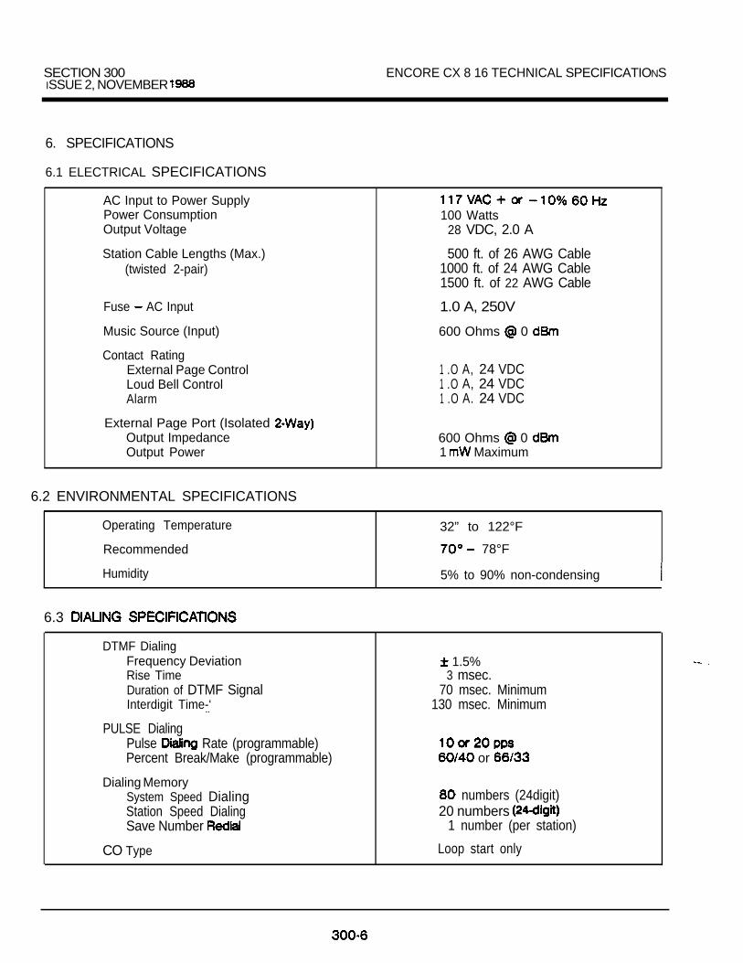
SECTION 300ISSUE 2, NOVEMBER
ENCORE CX 8 16 TECHNICAL SPECIFICATIONS
6. SPECIFICATIONS
6.1 ELECTRICAL SPECIFICATIONS
AC Input to Power SupplyPower ConsumptionOutput Voltage
Station Cable Lengths (Max.)(twisted 2-pair)
Fuse AC Input
Music Source (Input)
Contact RatingExternal Page ControlLoud Bell ControlAlarm
External Page Port (Isolated Output ImpedanceOutput Power
100 Watts28 VDC, 2.0 A
500 ft. of 26 AWG Cable1000 ft. of 24 AWG Cable1500 ft. of 22 AWG Cable
1.0 A, 250V
600 Ohms 0
1 .O A, 24 VDC1 .O A, 24 VDC1 .O A. 24 VDC
600 Ohms 0 1 Maximum
6.2 ENVIRONMENTAL SPECIFICATIONS
Operating Temperature 32” to 122°F
Recommended 78°F
Humidity 5% to 90% non-condensing
6.3
DTMF DialingFrequency DeviationRise TimeDuration of DTMF SignalInterdigit Time-‘
PULSE DialingPulse Rate (programmable)Percent Break/Make (programmable)
Dialing MemorySystem Speed DialingStation Speed DialingSave Number
CO Type
1.5%3 msec.
70 msec. Minimum130 msec. Minimum
or
numbers (24digit)20 numbers
1 number (per station)
Loop start only

ENCORE CX 8 16 TECHNICAL SECTION 300ISSUE 2, NOVEMBER
6.4 DIMENSIONS AND WEIGHT
KEY SERVICE UNITHeightWidthDepthWeight
KEY TELEPHONEHeightWidthDepth Weight
16.5“11.75”3.0”
17.6 lb.
8.75”8.75”2.75”3.4 lb.
PHONE BOXH e i g h tWidthDepthWeight
EXPANSION MODULEHeightWidth
Weight
1.75”5.5”4.0”1 lb.
1 1 5.5”11.76 lb.
6.5 PORT
DATA FORMAT Asynchronous, bits, 2 stop bits, no parity
DATA RATE baud (bps)
DATA PROTOCOL A high signal on pin 4 and pin 20 (DSR) l nabiosoutput and a low signal inhibits output A high signal is providedon pin (RTS) and pin 6 (DTR) at times.
PRINTER OUTPUT Character set data provided in the form of standard numericalcode (ASCII). and format is and/orprogrammable.
6.6 BUFFERING TABLE 1. CONNECTION REFERENCE CHART
SYSTEM CALL RECORD BUFFER FULLTYPE BUFFER HEADER
816 YES
6.7 SMDR PRINTED
l “SMDRMTALOBT*g*
This message is printed if more than 16 callrecords are generated by the phone systemwhile the printer is off-line; the system canstore a maximum of 16 call
KSU
2
3
4 4
5 CTS
6 6
Data
CTS Transmit Data
To SendDTR Data Terminal Ready
signal Ground
To
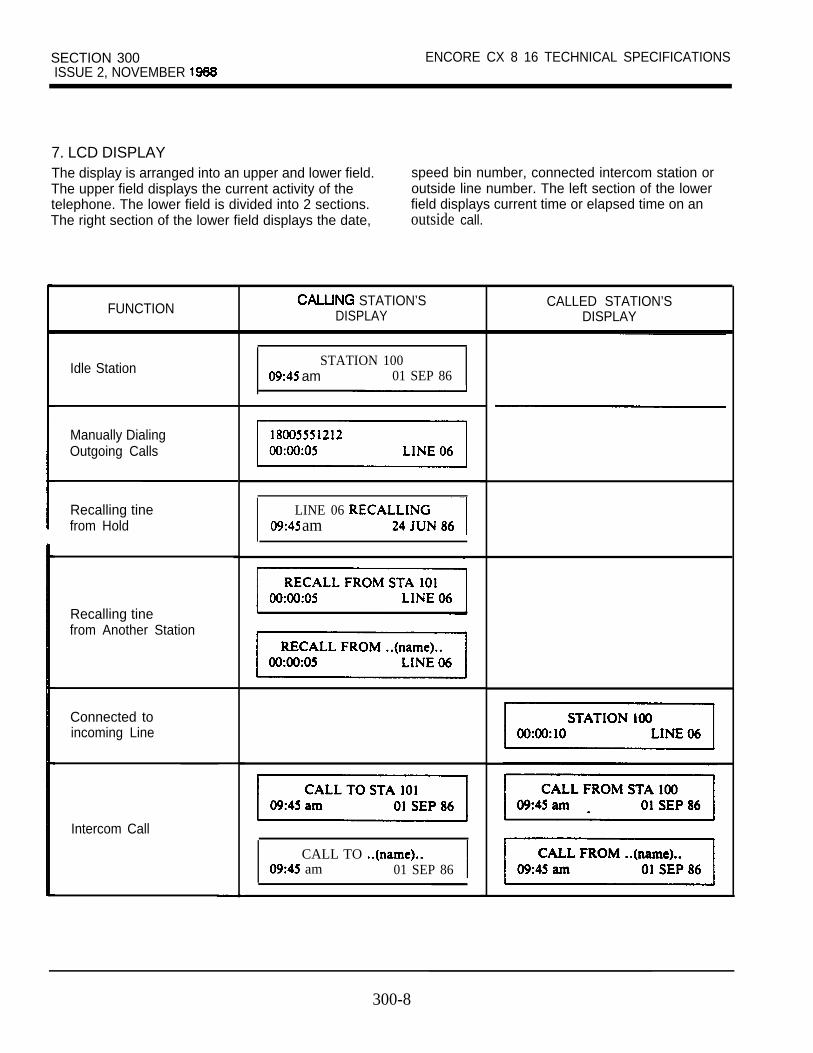
SECTION 300ISSUE 2, NOVEMBER
ENCORE CX 8 16 TECHNICAL SPECIFICATIONS
7. LCD DISPLAYThe display is arranged into an upper and lower field.The upper field displays the current activity of thetelephone. The lower field is divided into 2 sections.The right section of the lower field displays the date,
speed bin number, connected intercom station oroutside line number. The left section of the lowerfield displays current time or elapsed time on anoutside call.
FUNCTION
Idle Station
Manually DialingOutgoing Calls
Recalling tine LINE 06from Hold am
Recalling tinefrom Another Station
Connected toincoming Line
Intercom Call
STATION’SDISPLAY
STATION 100 am 01 SEP 86
CALL TO am 01 SEP 86
CALLED STATION’SDISPLAY
300-8

ENCORE CX 8 1 6 TECHNICAL SPECIFICATIONS SECTION 300ISSUE 2. NOVEMBER 1988
7. LCD DISPLAY (CONT’D)
FUNCTION
Conference
Internal Page
External Page
All Call Page
Message Waiting
Replying to aMessage Waiting
Station Call (Originating Station)
3672 system.
STATION’SDISPLAY
CONFERENCE am 21 SEP 86
INTERNAL PAGE am ZONE 1
EXTERNAL PAGE am ALL CALL
86
86
CALL TO am 30 SEP 86
CALLED STATION’SDISPLAY
CAMP-ON BY STA 100 am 01 SEP 86
CAMP-ON BY ..(name).. am
8 6
86
PAGE FROM . .(name). . am 21 OCT 86

SECTION 300ISSUE 2. NOVEMBER 1 9 8 8
ENCORE CX 8 16 TECHNICAL SPECIFICATIONS
7. LCD DISPLAY (CONT’D)
FUNCTION CALLING STATION’SDISPLAY
CALLED STATION’SDISPLAY
Forwarded Call
Preset
Hunt Groups
Queuing
Outside tine Transfer
Programmed FlashCommand (F)
Programmed PauseCommand (P )
10

ENCORE CX 8 16 TECHNICAL SPECIFICATIONS SECTION 300ISSUE 2, NOVEMBER
7. LCD DISPLAY (CONT’D)
FUNCTION
Programmed Tone Switchover (S)
STATION’S
- -
CALLED STATION’SDISPLAY
Call Pickup
Exclusive Hold
Meet Me Page
Do Not Disturb
Ringing tines
Call Back
Intercom CallFor initiator only: hdd initiator only:
Automatic Callback**
l * I nese features are available with PM-3 software only.
300-l 1

SECTION 300 ENCORE cx 8 16 TECHNICAL SPECIFICATIONSISSUE 2. NOVEMBER 1988
8. NUMBERING PLAN
1 0 0 - l 152 5 0 - 2 5 52 6 0 - 2 6 737 07 1
7 37 57 7
90
x 2
X 6
l 1XX
SPEED l
Station NumbersCall ParkHunt Group Pilot NumbersCamp-On (Call Wait)Night Service
Code EnterPre-Selected Messages (XX= 00-10)Background MusicAlarm ResetUniversal Night AnswerLoop Key
Group AccessIndividual Outside Line Access (XX= 01 Line Group AccessAttendant
Page Zone 1Internal Page Zone 2Internal All CallExternal ZoneMeet Me Page AnswerDirected Call Pickup station number)Group PickupSave Number Last Number
300-l 2
ENCORE CX 3672 SECTION 30 1KEY TELEPHONE SYSTEM ISSUE 2. NOVEMBER 1988
ENCORE CX 3672 TECHNICAL SPECIFICATIONS
TABLE OF CONTENTS
DESCRIPTION PAGE
1.
2
INTRODUCTION . . . . . . . . . . . . . . . . . . . . . . . . . . . . . . . . . . . . . . . . . . . . . . . . . . . . . . . . 1
SYSTEM CAPACITY2.1 12.2 ENCORE CX 3672 . . . . . . . . . . . . . . . . . . . . . . . . . . . . . . . . . . . . . . . . . . . . . . . . 1
3. DIMENSIONS AND WEIGHT3.1 KEY SERVICE UNIT . . . . . . . . . . . . . . . . . . . . . . . . . . . . . . . . . . . . . . . . . . . . . . . 13.2 EXPANSION KEY SERVICE UNIT . . . . . . . . . . . . . . . . . . . . . . . . . . . . . . . . . . . . 13.3 DSS CONSOLE . . . . . . . . . . . . . . . . . . . . . . . . . . . . . . . . . . . . . . . . . . . . . . . . . . . 1
4. AUDIBLE SIGNALS. . . . . . . . . . . . . . . . . . . . . . . . . . . . . . . . . . . . . . . . . . . . . . . . . . . . . . . 2
5.
6.
NUMBERINGPLAN . . . . . . . . . . . . . . . . . . . . . . . . . . . . . . . . . . . . . . . . . . . . . . . . . . . . . . . . . 4
PORT6.1 SMDR CALL RECORD BUFFERING . . . . . . . . . . . . . . . . . . . . . . . . . . . . . . . . . . . . .
7. LCD FEATURE PACKAGE 5 FEATURES . . . . . . . . . . . . . . . . . . . . . . . . . . . . . . 6
8. ADDITIONAL SPEED DIAL BINS . . , . . . . . . . . . . . . . . . . . . . . . . . . . . . . . . . . . 6
LIST OF TABLES
1. CONNECTION REFERENCE CHART . . . . . . . . . . . . . . . . . . . . . . . . . . . . . . . . 5
301 -A
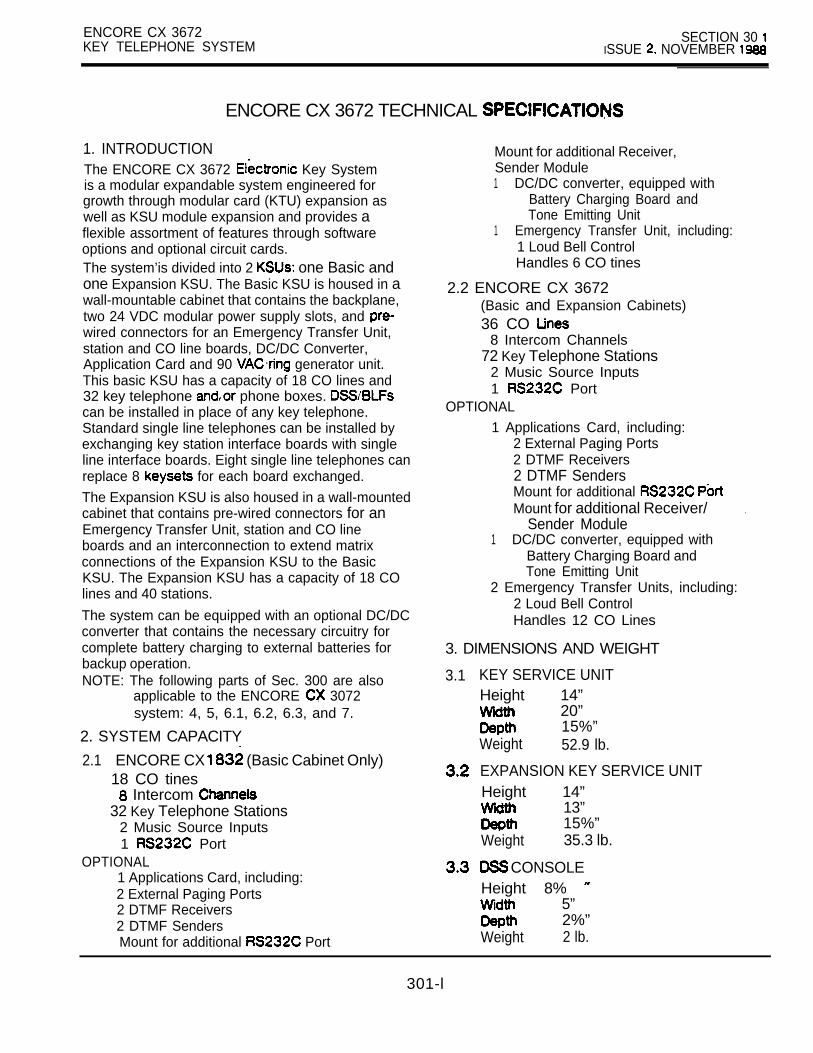
ENCORE CX 3672KEY TELEPHONE SYSTEM
SECTION 30 ISSUE NOVEMBER
ENCORE CX 3672 TECHNICAL
1. INTRODUCTIONThe ENCORE CX 3672 Key Systemis a modular expandable system engineered forgrowth through modular card (KTU) expansion aswell as KSU module expansion and provides aflexible assortment of features through softwareoptions and optional circuit cards.The system’is divided into 2 one Basic andone Expansion KSU. The Basic KSU is housed in awall-mountable cabinet that contains the backplane,two 24 VDC modular power supply slots, and wired connectors for an Emergency Transfer Unit,station and CO line boards, DC/DC Converter,Application Card and 90 generator unit.This basic KSU has a capacity of 18 CO lines and32 key telephone phone boxes. can be installed in place of any key telephone.Standard single line telephones can be installed byexchanging key station interface boards with singleline interface boards. Eight single line telephones canreplace 8 for each board exchanged.
The Expansion KSU is also housed in a wall-mountedcabinet that contains pre-wired connectors for anEmergency Transfer Unit, station and CO lineboards and an interconnection to extend matrixconnections of the Expansion KSU to the BasicKSU. The Expansion KSU has a capacity of 18 COlines and 40 stations.
The system can be equipped with an optional DC/DCconverter that contains the necessary circuitry forcomplete battery charging to external batteries forbackup operation.NOTE: The following parts of Sec. 300 are also
applicable to the ENCORE 3072system: 4, 5, 6.1, 6.2, 6.3, and 7.
2. SYSTEM CAPACITY
2.1 ENCORE CX (Basic Cabinet Only)18 CO tines
Intercom 32 Key Telephone Stations
2 Music Source Inputs1 Port
OPTIONAL1 Applications Card, including:2 External Paging Ports2 DTMF Receivers2 DTMF SendersMount for additional Port
Mount for additional Receiver,Sender Module1 DC/DC converter, equipped with
Battery Charging Board andTone Emitting Unit
1 Emergency Transfer Unit, including:1 Loud Bell ControlHandles 6 CO tines
2.2 ENCORE CX 3672(Basic and Expansion Cabinets)36 CO
8 Intercom Channels72 Key Telephone Stations
2 Music Source Inputs1 Port
OPTIONAL1 Applications Card, including:
2 External Paging Ports2 DTMF Receivers2 DTMF SendersMount for additional Mount for additional Receiver/ .
Sender Module1 DC/DC converter, equipped with
Battery Charging Board andTone Emitting Unit
2 Emergency Transfer Units, including:2 Loud Bell ControlHandles 12 CO Lines
3. DIMENSIONS AND WEIGHT
3.1 KEY SERVICE UNITHeight 14”
20”15%”
Weight 52.9 lb.
EXPANSION KEY SERVICE UNITHeight 14”
13”15%”
Weight 35.3 lb.
CONSOLEHeight 8%
5” 2%”
Weight 2 lb.
301-l

SECTION 301 ENCORE CX 3672 TECHNICAL SPECIFICATIONSISSUE 2. NOVEMBER
4. AUDIBLE SIGNALS SINGLE LINE TELEPHONES
TIMING CHART FREQUENCY CYCLE(Seconds)TONE SIGNAL
0 1 2 3
off
IncomingCO tine
0 1 2 3 4 5 sec.
1 on/4 off Intercom Ring
0 1 3 4 sec.
off
Transferred andRecalling CO LineQueueCall Back
0 1 3 4 sec.
off440 Intercom
0 1 3 4 sec.
440 Hz off3 burstsAnnounce
to a
Busy Tone
0 1 2 3 4 5 sec.
440 Hz on/.5 off
440 HzError Tone on/.25 off
0 1 2 3 4
DND Tone off440
1 2 3 .
PagingAlert
0 1 2 3 4
440 Hz 1 sec. burst

ENCORE CX 3672 TECHNICAL SPECIFICATIONS SECTION 301ISSUE 2. NOVEMBER
4. AUDIBLE SIGNALS (CONT’D)
TONE SIGNAL TIMING CHART FREQUENCY CYCLE(Seconds)
Call Warning Tone
440 Hz 1 sec. burst
DND WarningTone
440 Hz off3 bursts
sec.
ConferenceTime Out
Camp-On
ConferenceWarning Tone
ConfirmationTone
440 Hz on/.2 off
0 1 2 3
440 Hz sec. burst
440 Hz 1 sec. burst
440 Hz 1 sec. burst

I IUN
3 . NOVEMBER
5. NUMBERING PLAN
100-1992 0 0 - 2 1 12 4 0 - 2 4 72 5 0 - 2 5 52 6 0 - 2 6 72 7 0 - 2 7 72 7 02 7 9
291
292293
294
295296
297
298
2993
5 9
6 06 9 06 9 16 9 2
6 9 3
Station numberingStation NumberingVoice Mail Group NumbersCall Park LocationsHunt Group Pilot NumbersUCD Group NumbersUCD DND (Toggle On and Off)UCD Status Display (Calls inQueue)EPB Software Version (Attendant
Custom Message Programming“Dial Memo” Button (Assignment
“Auto Button(Assignment Only)Program Name in Display Forward CO Line Off-Net (Attendant
Background Music(Attendant Only)CO Line Outgoing Call Disable/Enable (Attendant Only)Set System Clock (Attendant Only)Camp-On (with busy signal fromintercom call attempt)Queue Cancel (LCR)Voice Mail MSG Indication On(Voice Mail Stations Only)Flash Command to CO LinePersonal ParkDND (Toggle Call ForwardSpeed Dial ProgrammingMessage Wait/Callback Message Wait/Callback ReturnVoice Mail Indication OFF(Voice Mail Station Cancel DND, Call Forward, Message Speed Dial AccessLast Number RedialForce Ringing on IntercomCallsConference with Personal Park
Button (Assignment Only) Button (Assignment Only)
Button (Assignment
Button (Assignment
0
“FLASH” Button (Assignment Only)“MUTE’ Button (Assignment Only)
Button (Assignment Only)Answer Mode (Toggle for ToneRinging or Hands Free)Program Station Flexible ButtonsNight ServiceAccount Code Enter (ButtonAssignment Only)Background Music (Toggle BGM)Alarm Reset Only)Intercom on hold Button(Assignment Only)Universal Night AnswerAttendant Override (Assignment
LOOP Button (Assignment Only)CO Group 1 Access LCRVersion Software)CO Group 2 AccessCO Group 3 AccessCO Group 4 AccessCO Group AccessCO Group 6 AccessCO Group 7 AccessCO Group 8 Access Only)CO Group Access or LCR AccessWith LCR ActiveAttendantDirected Call PipDirected Call PiiupProgramming Mode (Extension100 Only)Group Call PickupAll Page External Zones)Page Internal Zone1Page Internal Zone 2Page Internal Zone 3
SPEED l Last Number RedialSPEED + SPEED Save Number DialedSPEED + Saved Number Redial
Page Internal Zone 4
All Page (Internal Zones Only)Page External Zone 1Page External Zone 2
All Page (External Zones, Only)
Meet Me Page
694695696699
71
7 37 57 6
7 77 8
7 98 0
6 18 2
8 48 58 66 79
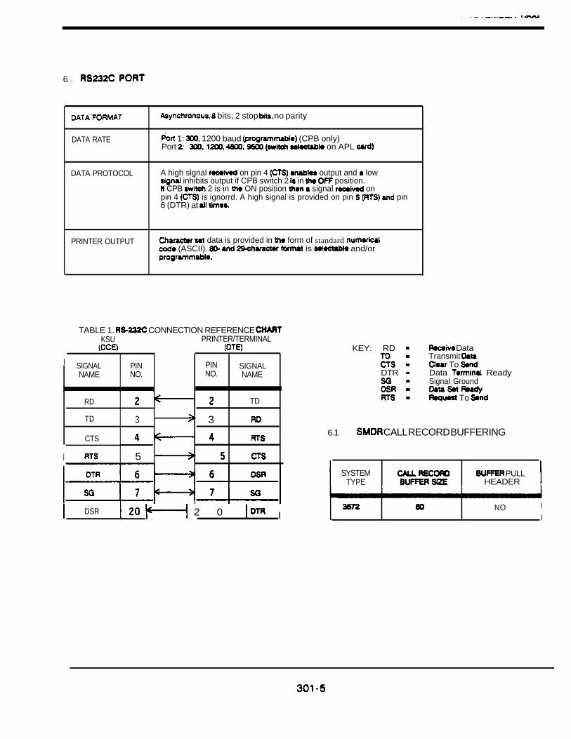
6 .
DATA RATE
bits, 2 stop no parity
1: 1200 baud (CPB only)Port on APL
DATA PROTOCOL A high signal on pin 4 output and low inhibits output if CPB switch 2 in position.
CPB 2 is in ON position signal onpin 4 is ignorrd. A high signal is provided on pin pin6 (DTR) at
PRINTER OUTPUT data is provided in form of standard (ASCII). is and/or
TABLE 1. CONNECTION REFERENCE KSU PRINTER/TERMINAL
I SIGNAL PIN PIN SIGNALNAME NO. NO. NAME
,
RD TD
TD 3 3
CTS
I 5
DSR 2 0 I
KEY: RD Data
Transmit
To DTR Data Ready
Signal Ground
To
6.1 CALL RECORD BUFFERING
SYSTEM PULLTYPE HEADER ,
NO II

SECTION 301 ENCORE CX 3672 TECHNICAL SPECIFICATIONSISSUE 2. NOVEMBER
7. LCD DISPLAY: FEATURE PACKAGE FEATURES
FUNCTION CALUNG STATION’S DISPLAY
Automatic ,Callback
Intercom Call For hold initiator only:Hold I
STA 105 HOLDING 1I L - - i
Display Security
Station Call
(Off-Premise)
I. . .
Voice Mail(station calling station forwarded PM CALLED118
, to voice mail)
Voice Mail(station callingvoice mail topick up mail)
8. ADDITIONAL SPEED DIAL BINS
CALLED STATION’S DISPLAY
For hdd initiator only:
STA 111
FORWARDED10 SPEED 01 PM .
3016
ENCORE CX SECTION 302FIELD CONVERSION KIT ISSUE 1, JULY 1988
ENCORE CX 36112 TECHNICAL SPECIFICATIONS
TABLE OF CONTENTS
DESCRIPTION PAGE
1. INTRODUCTION. . . . . . . . . . . . . . . . . . . . . . . . . . . . . . . . . . . . . . . . . . . . . . . . . . . . . . . . 1
2. SYSTEM CAPACITY .. . . . . . . . . . . . . . . . . . . . . . . . . . . . . . . . . . . . . . . . . . . . . . . . . . . 12.1 OPTIONAL . . . . . . . . . . . . . . . . . . . . . . . . . . . . . . . . . . . . . . . . . . . . . . . . . . . . . . . . . 1
3. DIMENSIONS AND WEIGHT .. . . . . . . . . . . . . . . . . . . . . . . . . . . . . . . . . . . . . . . . . . 13.1 BASIC KEY SERVICE UNIT . . . . . . . . . . . . . . . . . . . . . . . . . . . . . . . . . . . . . . . . . 13.2 POWER CAGE . . . . . . . . . . . . . . . . . . . . . . . . . . . . . . . . . . . . . . . . . . . . . . . . . . . . . 23.3 EXPANSION KSU. . . . . . . . . . . . . . . . . . . . . . . . . . . . . . . . . . . . . . . . . . . . . . . . . . . 2
302-A

ENCORE CX 36112 SECTION 302FIELD CONVERSION KIT 1. JULY
ENCORE CX 36112 TECHNICAL SPECIFICATIONS
1. INTRODUCTION
The ENCORE CX 36112 Field ConversionKit is a modular expandable systemengineered for growth through modularcard (KTU) expansion as well as KSUmodule expansion. I t p r o v i d e s aflexible assor tment o f featuresthrough software options and optionalcircuit cards. The Field ConversionK i t i n c l udes t he f o l l ow ing : oneExpansion KSU and one power cage.Adding this equipment makes theENCORE CX 3672 system expandable toan ENCORE CX 38112 system.
The system is divided into 2 one Basic and one Expansion KSU. TheBasic KSU is housed in a wallmountable cabinet that contains thebackplane, two 24 VDC modular power
slots, and pre-wiredconnectors for an Emergency TransferUnit, station and CO line boards,DC/DC converter, Application Card and
VAC ring generator unit. This isthe same Basic KSU that is used forthe ENCORE CX 3872 system. The BasicKSU has a capacity of 18 CO lines and32 key telephones and/or phone boxes.
can be installed in place ofany key telephone. Standard singleline telephones can be installed byexchanging key station.. interfaceb o a r d s w i t h s i n g l e l i n einterface boards (SI Eightsingle line telephones can replace 8
for each board exchanged.
The Expansion KSU is also housed in awall mounted cabinet that containspre-wired connectors for an EmergencyTransfer Unit, station and CO lineboards and an interconnection toextend matr ix connect ions of theExpansion KSU to. the Basic KSU. TheExpansion KSU also includes a power
cage which mounts to the right ofthe Basic KSU and houses the thirdpower supply which controls cardslots The Expansion KSU hasa capacity of 18 CO lines, 80stations, a second APL card and anEIB card. It also contains a secondDC/DC converter, which is requiredif KIB card slots 15-21 are used.
2. SYSTEM CAPACITY
3616
112
l
CO linesIntercom Channels’Key Telephone StationsMusic Source InputsExternal Paging Ports
PortOption Card Ports
(See Section 402)
2.1 OPTIONAL
1 PortSystem Battery Backup
Emergency Transfer Circuits SLT Ring Generator
2 APL Cards
3. DIMENSIONS AND WEIGHT
3.1 BASIC KEY SERVICE UNIT
Height 14”Wid th 20”Depth 15 Weight 52.9 lb.
302-l

SECTION 302 ENCORE CX 36112 FIELD CONVERSION KITISSUE 1. JULY 1966
3.2 POWER CAGE
Height 14”Width 6 114”Depth 314”Weight 14.5 lb.
3.3 EXPANSION KSU
Height 13 314”Width 26 114”Depth 15 Weight 70.75 lb.

ENCORE CX SECTION 400KEY TELEPHONE SYSTEM ISSUE 2, NOVEMBER 1989
DESIGN AND CONFIGURATION
TABLE Of CONTENTS
1.
2.
3.
4.
5.
8.
7.
. 8.
9.
10.
11.
DESCRIPTION PAGE
. . . . . . . . . . . . . . . . . . . . . . . . . . . . . . . . . . . . . . . . . . . . . . . . . . . . . . 1
GENERAL . . . . . . . . . . . . . . . . . . . . . . . . . . . . . . . . . . . . . . . . . . . . . . . . . . . . . . . . . . . 1
POWER REQUIREMENTS . . . . . . . . . . . . . . . . . . . . . . . . . . . . . . . . . . . . . . . . . . . . . . 1
PLAN . . . . . . . . . . . . . . . . . . . . . . . . . . . . . . . . . . . . . . . . . . . . . . . . . 34.1 GENERAL APPROACH . . . . . . . . . . . . . . . . . . . . . . . . . . . . . . . . . . . . . . . . . . 34.2 ENVIRONMENTAL FACTORS . . . . . . . . . . . . . . . . . . . . . . . . . . . . . . . . . . .4.3 SITE PLANNING . . . . . . . . . . . . . . . . . . . . . . . . . . . . . . . . . . . . . . . . . . . . . . . 34.4 STRUCTURAL CONSIDERATIONS . . . . . . . . . . . . . . . . . . . . . . . . . . . . . . .4.5 CABLING CONSIDERATIONS . . . . . . . . . . . . . . . . . . . . . . . . . . . . . . . . . . . . 54.8 TELCO INTERFACE . . . . . . . . . . . . . . . . . . . . . . . . . . . . . . . . . . . . . . . . . . . . 5
PROGRAMMING WORKSHEETS . . . . . . . . . . . . . . . . . . . . . . . . . . . . . . . . . . . . . . . 105.1 SYSTEM PARAMETERS . . . . . . . . . . . . . . . . . . . . . . . . . . . . . . . . . . . . . . . 11
CO LINE PROGRAMMING . . . . . . . . . . . . . . . . . . . . . . . . . . . . . . . . . . . . . . 13STATION PROGRAMMING . . . . . . . . . . . . . . . . . . . . . . . . . . . . . . . . . . . . . 14 .BUTTON ASSIGNMENT CHART . . . . . . . . . . . . . . . . . . . . . . . . . . . . . . . . . 15SYSTEM SPEED NUMBERS . . . . . . . . . . . . . . . . . . . . . . . . . . . . . . . . . . . .EXCEPTION TABLES . . . . . . . . . . . . . . . . . . . . . . . . . . . . . . . . . . . . . . . . . . 18
5.7 SPECIAL TABLES . . . . . . . . . . . . . . . . . . . . . . . . . . . . . . . . . . . . . . . . . . . . . 19
FEATURE PACKAGE V . . . . . . . . . . . . . . . . . . . . . . . . . . . . . . . . . . . . . . . . . . . . . . . . 20
UNIFORM CALL DISTRIBUTION (UCD) . . . . . . . . . . . . . . . . . . . . . . . . . . . . . . . . .7.1 OPERATION . . . . . . . . . . . . . . . . . . . . . . . . . . . . . . . . . . . . . . . . . . . . . . . . . 207.2 CONDITIONS . . . . . . . . . . . . . . . . . . . . . . . . . . . . . . . . . . . . . . . . . . . . . . . . 20
REMOTE . . . . . . . . . . . . . . . . . . . . . . . . . . . . . . . . . . . . . . . . . . . . . 21
VOICE MAIL . . . . . . . . . . . . . . . . . . . . . . . . . . . . . . . . . . . . . . . . . . . . . . . . . . . . . . . . 219.1 INSTALLATION . . . . . . . . . . . . . . . . . . . . . . . . . . . . . . . . . . . . . . . . . . . . . . . 229.2 . . . . . . . . . . . . . . . . . . . . . . . . . . . . . . . . . . . . . . . . . . . . . . . . . 229.3 CONDITIONS . . . . . . . . . . . . . . . . . . . . . . . . . . . . . . . . . . . . . . . . . . . . . . . . 239.4 PROGRAMMING EXAMPLE: VOICE MAIL SYSTEM . . . . . . . . . . .
REMOTE MAINTENANCE . . . . . . . . . . . . . . . . . . . . . . . . . . . . . . . . . . . . . . . . . . . . . 2410.1 GENERAL OVERVIEW . . . . . . . . . . . . . . . . . . . . . . . . . . . . . . . . . . . . . . . . .10.2 OVERVIEW OF MAINTENANCE COMMANDS . . . . . . . . . . . . . . . . . . . . . . .10.3 MAINTENANCE COMMANDS . . . . . . . . . . . . . . . . . . . . . . . . . . . . . . . . . . . 2410.4 EXIT MAINTENANCE . . . . . . . . . . . . . . . . . . . . . . . . . . . . . . . . . . . . . . . . . . 24
FEATURE PACKAG; VI PROGRAMMING WORKSHEETS . . . . . . . . . . . . . . . . . . .
400-A

SECTION 400 ENCORE CX DESIGN AND CONFIGURATION
OF FIGURES
SYSTEM BLOCK DIAGRAM . . . . . . . . . . . . . . . . . . . . . . . . . . . . . . . . . . . . . . . . . . . . . . . 83672 SYSTEM BLOCK DIAGRAM . . . . . . . . . . . . . . . . . . . . . . . . . . . . . . . . . . . . . . . . . . . . . . 9
3. KEYPAD/TERMINAL EQUIVALENTS . . . . . . . . . . . . . . . . . . . . . . . . . . . . . . . . . . . . . . . . ..2 14. SAMPLE ENCORE CX 3672 CONFIGURATION (WITHOUT LCA) . . . . . . . . . . . . . . . . . .5. SAMPLE ENCORE CX 36112 CONFIGURATION (WITH LCR) . . . . . . . . . . . . . . . . . . . . .6. . . . . . . . . . .7. SAMPLEOFWHATISPRlNTEDWHENTHElNSTALLERENTERSDS4.. . . . . . . . . . .8. SAMPLE OF WHAT IS PRINTED WHEN THE INSTALLER ENTERS D S5 . . . . . . . . . . . .9. SAMPLE OF WHAT IS PRINTED WHEN THE INSTALLER ENTERS D . . . . . . . . . . . .10. SAMPLE OF WHAT IS PRINTED WHEN THE INSTALLER ENTERS . . . . . . . . . . . . . . .
LIST OF TABLES
SURVEY DATA REQUIREMENTS . . . . . . . . . . . . . . . . . . . . . . . . . . . . . . . . . . . . . . . . . . . . . . 22. INSTALLATION SEQUENCE. . . . . . . . . . . . . . . . . . . . . . . . . . . . . . . . . . . . . . . . . . . . . . . . . . 33. ENVIRONMENTAL CONSIDERATIONS . . . . . . . . . . . . . . . . . . . . . . . . . . . . . . . . . . . . . . . .4. LIST OF COMPONENTS . . . . . . . . . . . . . . . . . . . . . . .. . . . . . . . . . . . . . . . . . . . . . . . . . . . . . 8
ENCORE CX SECTION 400KEY TELEPHONE SYSTEM ISSUE MAY 1987
DESIGN AND CONFIGURATION
1. INTRODUCTIONProper planning minimizes the time required andcosts incurred during an installation. Maintenance,changes and expansion can be accomplishedefficiently when planned prior to the initial installation.This results in customer satisfaction and good willthrough a minimum of disruption to their businessactivities.This section is presented in 3 parts. The firstprovides a survey of planning details that shouldbe considered prior to installing an ENCORE CXsystem. The second part presents a typical systemlayout for use in developing a detailed system plan.The third part briefly discusses system programmingand the information required to plan a customer’ssystem. Worksheets are provided to assist ingathering this information.
2. GENERALNormally a survey of the customer’s facilities is madefor the purpose of developing a cost the installed system. This survey developspreliminary data that is often insufficient to allow fordetailed planning of the actual installation. approaching this survey in a manner designed tohighlight required information, the cost estimatesurvey can be more effectively used in the detailedplanning state. This will eliminate, in most cases,the need for a second visit to data.
A cost estimate details what equipment is requiredand how many of each type. However, realisticplacement of the equipment and area dimensionsare sometimes overlooked. It is here where majorcost savings can be made since the time factorrequired to accomplish the installation is a majorvariable. Each factor affecting system planning isdiscussed in detail in this section.Table 1 presents in question format the type of datarequired to convert a cost estimate survey into adetailed system plan. Prior to completion of the initialvisit, review the questions in the table to ensure thatall pertinent data has been obtained.
3. POWER REQUIREMENTSThe system requires a power source capable ofproviding 117 VAC single phase power at 60 Hz.The power source must have the capacity to deliver15 amperes.The facility power line must be a dedicated lineequipped with a surge protector in order to helpprotect the system against erratic operations anddamage. In addition, the outlet of the facility powersource must be located within reach of the 6’ longpower cord supplied with the system power supply.
4 0 0 - l
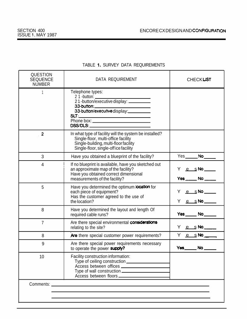
SECTION 400 ENCORE CX DESIGN AND ISSUE MAY 1987
TABLE SURVEY DATA REQUIREMENTS
QUESTIONSEQUENCE DATA REQUIREMENT CHECK
NUMBER
1 Telephone types:2 1 -button:2 1 -button/executive display:
display:
Phone box:
In what type of facility will the system be installed?Single-floor, multi-office facilitySingle-building, multi-floor facilitySingle-floor, single-off ice facility
3
4
5
8
7
8
9
10
, Have you obtained a blueprint of the facility? Yes
If no blueprint is available, have you sketched outan approximate map of the facility? Y e sHave you obtained correct dimensionalmeasurements of the facility?
Have you determined the optimum foreach piece of equipment? Y e sHas the customer agreed to the use ofthe location? Y e s
Have you determined the layout and length Ofrequired cable runs?
Are there special environmental relating to the site? Y e s
there special customer power requirements? Y e s
Are there special power requirements necessaryto operate the power
Facility construction information:Type of ceiling constructionAccess between officesType of wall constructionAccess between floors
Comments:

ENCORE CX DESIGN AND CONFIGURATION SECTION 400ISSUE MAY 1987
4. INSTALLATION PLAN TABLE 2. INSTALLATION SEQUENCE
There are many approaches to developing a systeminstallation plan. The following section describes ageneral approach for a typical installation. Includedwill be standard considerations that affect equipmentplacement, environmental and cabling requirements,and interface information between telephonecompany equipment and the ENCORE CX system.A better understanding of the various stages of a jobnormally results in more careful planning, preparationand coordination of the job efforts.
4.1 GENERAL APPROACHAn overview of the system installation process canprovide sates personnel with greater insight into thekind of information needed to develop a detailedsystem plan. Each customer’s facility is differentand requires a tailored approach to ensure thatthe job runs smoothly. Each facility will have its owncombination of circumstances which must beaddressed. Table 2 summarizes the major stages ofa typical telephone installation. The order in whichthe steps are performed can be reflectthe particular circumstances of each installation.However the general approach should include allthe installation steps provided in Table 2.
STEP INSTALLATION STAGE
1. Site survey and data collection.2. Plan major equipment layout.
(MDF, KSU, system power supplyand position of the attendants.)
3. Plan MDF block layout and cablerouting.
4. Preparation and preassembly of KSU,power supply and MDF at shopfacility.
5. Site work:a. Running of station cables.b. Equipment mounting.
(MDF, KSU, power supply, etc.)c. MDF and remote terminal
connections.
6.7.
d. Telephone and DSS e. System programming.System checkout.Customer introduction and training.
4.3 SITE PLANNING
4.2 ENVIRONMENTAL FACTORSThe environment where a telephone system islocated affects the reliability and of system. These factors, if not properly monitored,may lead to system failures, can resultin excessive customer service calls and customerdissatisfaction. A summary of the environmentalfactors affecting the ENCORE CX TelephoneSystem is presented in Table 3. These factors mustbe considered when developing a systemplan.
Site preparation is dependent upon the customer’sfacilities. In many cases, there may be only one
where the KSU, power supply and MDFcan be mounted. However, when several locationsare possible, the advantages and disadvantages ofeach location should be considered. Non-structuralconsiderations:A The KSU is designed for wall-mounting only.
of the majority of Locate theKSU so that the length of cable runs can beminimized.

SECTION 400 ENCORE CX DESIGN AND CONFIGURATIONISSUE MAY 1987
ENVIRONMENTALPARAMETERS
Ambient light
Temperature
Humidity
Dust and airbornecontaminants
Water flooding
Accessibility
Electricalinterference
Vibration
TABLE 3. ENVIRONMENTAL CONSIDERATIONS
TO ENCORE EQUIPMENT
Sufficient light should be readily available to enable inspection, testing,and other functions to be performed at the common equipmentlocation.
The equipment contains semiconductors and other electroniccomponents that are very sensitive to heat. Adequate ventilation isrequired for the KSU to allow upward circulation of air through thecabinet grills.The KSU does not require any special cooling considerations, exceptto avoid mounting it near any heat generating objects, such as heatregisters.Sustained average temperature should not be greater than F
nor less than The telephones and DSS contain semiconductors; care must thereforebe taken to avoid placement in areas producing excessive amounts ofheat. The customer (end user) should be cautioned, at the time ofinstallation, about repositioning stations.
Avoid excessive humidity, which may cause condensation on metalsurfaces and consequently produce corrosion. The maximumpermissible humidity is 90% (non-condensing) and the minimumis 5% (relative).
Avoid placing equipment in areas where dust or other airbornecontaminants are present. Chemical fumes or vapors will cause
or oxidation of electrical contacts.
Avoid the equipment where the possibility of water damageexists: for instance, directly under overhead plumbing or on floorswhere flooding could occur.
The common equipment must be located where workingroom is available for two people. Locations where the equipment may beinadvertently hidden or blocked by placement of bulky items (such aspacking cases) should be avoided.
The equipment, (telephones, KSU, etc.) should be in anenvironment free of electrical interference. from transmitters,copy machines, arc welders, and other electrical apparatus can disturbthe operation of control circuits.
The equipment should be installed in a location free Of vibration disconnecting or loosening components.

ENCORE CX DESIGN AND CONFIGURATION SECTION 400ISSUE MAY 1987
4.3 SITE PLANNING
C.D.
E.
F.
G.
H.
Location of existing telephone ducts or conduits.The AC line should be dedicated exclusivelyto the system. If the line is equipped with a circuitbreaker at the service entrance panel, this switchshould be labeled “Do Not Turn Off”.The equipment should be installed in a wellventilated area having a temperature range of
degrees F with a recommendedtemperature range of degrees F and ahumidity range of (non-condensing).A good earth ground must be provided using 8gauge or larger wire. A cold water pipe withinsulated joints or meters by-passed with 8gauge or larger straps will also provide suitableground.Appropriate lighting conditions and adequateworking space should be provided for futureservice calls.Consideration must be given to those conditionsthat may cause damage to the equipment.For example, dust or vapor from flammable orcorrosive solvents may cause damage.The installation site should not be located in anarea likely to be flooded or damaged by movingobjects nearby.The KSU should not be located in an area near.electrical interference including equipment suchas heavy motors, welders, dimmers, radiotransmitters, copy machines, etc.
4.4 STRUCTURAL Wall mounting will proceed easily when equipmentis fastened to a mounting surface that has been securely attached to the wall. (A backboard such asplywood makes it convenient and safer for fasteningthe KSU, connecting blocks, cable and wirehangers, etc.)Refer to the Technical Specifications section of thismanual for loaded weights of each KSU to determinetype of fastener and fastening technique requiredfor the wail material and surface. Increase the safetyand security of this installation by:
A. Mounting the KSU on. a and notdirectly on a wall surface.
B.
C.
Using the proper fasteners to attach backboardto wall.Using the proper fasteners to attach ailequipment to the mounting surface.
4.5 REQUIREMENTS cabling used must conform to industry standard gauge inside wiring cable or twisted cable.
(OHVA requires 3 pair). Efforts should be made tostay within the following prescribed cable lengths:
500’ 26 AWG Cable1000 24 AWG Cable1500’ 22 AWG Cable
Station and DSS console cables are terminated atthe MDF by connecting blocks and associatedbridging clips. The bridging clips are used toestablish continuity between the KSU side of theblock and station side. These clips permit stationleads to be opened conveniently for testing andtroubleshooting purposes.Station cables are terminated at the station bystandard modular jacks. The modular jacks permitthe station leads to be opened conveniently fortesting and troubleshooting purposes.
4.6 TELCO INTERFACETelco lines must be terminated in an X jack forthe 3672 and C jacks for the 816 system.At the time the 11 C or the 1 X is ordered fromthe telephone company, you must thesequence in which the central office lines are to beconnected to the terminal. Telco will wire these linesto the terminal in accordance with the specifiedsequence.The 3672 KSU is equipped with an type connector that complies with USOC X
described in FCC regulations Title 47, Chapter Part 68. Connect this plug to the jack-terminatedcable provided by the telephone company.
required by regulation, the X will be placedwithin 25’ of the KSU location by the telephone
400-5
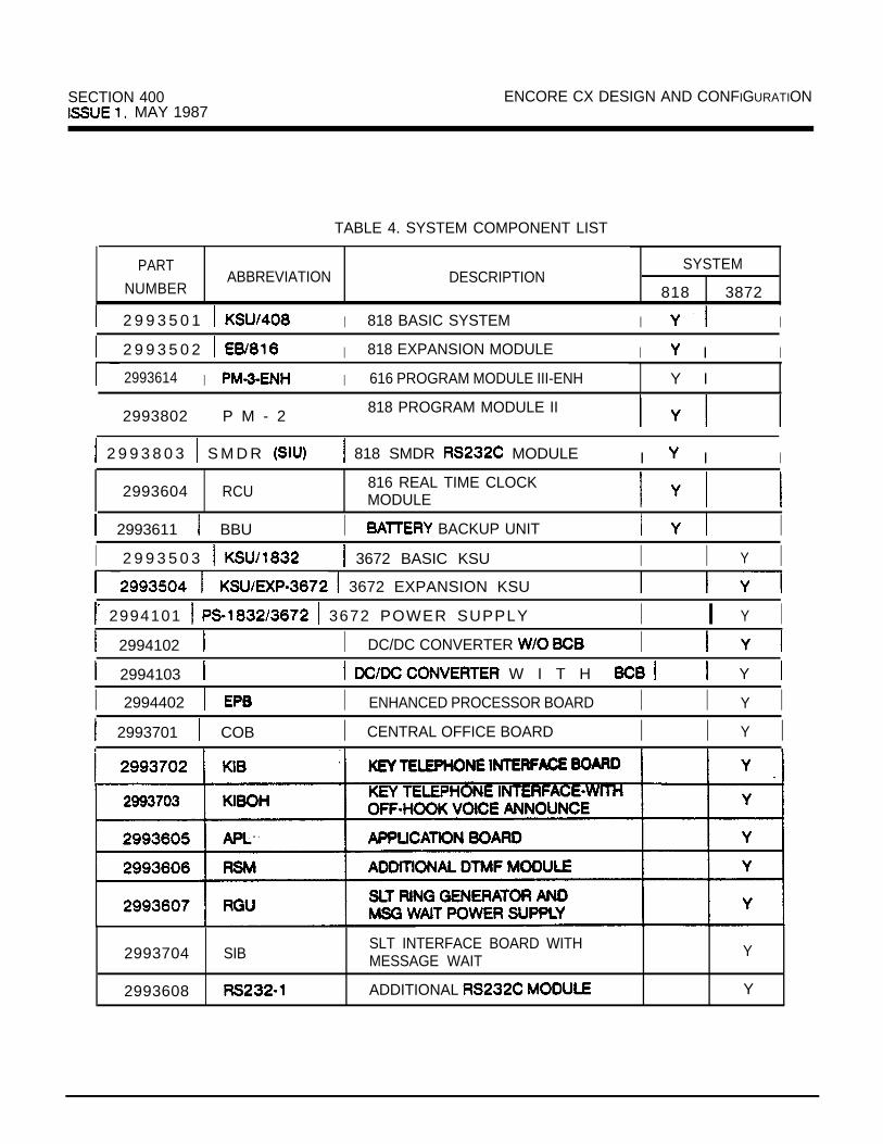
SECTION 400 ENCORE CX DESIGN AND CONFIGURATION MAY 1987
TABLE 4. SYSTEM COMPONENT LIST
PART
NUMBERABBREVIATION DESCRIPTION
SYSTEM
818 3872
2 9 9 3 5 0 1 I 818 BASIC SYSTEM I I
2 9 9 3 5 0 2 I 818 EXPANSION MODULE I I I
2993614 I I 616 PROGRAM MODULE III-ENH Y I
2993802 P M - 2 818 PROGRAM MODULE II
2 9 9 3 8 0 3 S M D R 818 SMDR MODULE I I I
2993604 RCU 816 REAL TIME CLOCKMODULE
2993611 BBU I BACKUP UNIT II 2 9 9 3 5 0 3 3672 BASIC KSU I I Y I
3672 EXPANSION KSU
2994101 3672 POWER SUPPLY I I Y I 2994102 I DC/DC CONVERTER I 2994103 W I T H Y
I 2994402 I ENHANCED PROCESSOR BOARD I I Y I 2993701 COB I CENTRAL OFFICE BOARD I I Y I
2993704 SIBSLT INTERFACE BOARD WITHMESSAGE WAIT
Y
2993608 ADDITIONAL Y

DESIGN AND CONFIGURATION SECTION 400ISSUE 2, NOVEMBER 1989
PARTNUMBER
299361’0
2992509
ABBREVIATION
ETU EMERGENCY TRANSFER MOD.
2992501 ENHANCED
KEY TELEPHONE
299250221 EXECUTIVEKEY TELEPHONE
2992503 ENHANCED
KEY TELEPHONE
2992504 EXECUTIVE
KEY TELEPHONE
2992505 DSS-46
2992506
2996300
2996301
2993705
2993706
2993505
2993612
2996302
2996303
2997301
PB-1 PHONE BOX
3672 BASIC
3672 SOFTWARE WITH LCR
COB-A AMPLIFIED CENTRAL OFFICE BOARD
SINGLE LINE OPX BOARD
E X P - 3 6 1 1 2 36112 EXPANSION CABINET
EIB EXPANDED INTERFACE BOARD
36112 BASIC SOFTWARE
36112 SOFTWARE WITH
SINGLE LINE ADAPTER
TABLE 4. SYSTEM COMPONENT LIST
DESCRIPTION
ENHANCEDKEY TELEPHONE
DIRECT STATION SELECTCONSOLE
SYSTEM
l 361 systems on/y
1616
Y
Y
Y
Y
Y
Y
Y
3672
Y
Y
Y
Y
Y
Y
Y
Y
Y
Y
Y.
.
.
l
400-7

1. CPU .I 2. 3 . 4 . 5. CLOCK6 .
I I- I
LOUD CTL
PAGE

ENCORE CX DESIGN AND CONFIGURATION SECTION 400ISSUE MAY 1987
FIGURE 2. 3672 SYSTEM BLOCK DIAGRAM

SECTION 400ISSUE MAY 1987
ENCORE CX DESIGN AND CONFIGURATION
5. PROGRAMMING WORKSHEETSEach customer’s system can be programmed tomeet individual needs. All programming (or dataentry) is done at station 100 using a key telephone.Programming can be done with a 21 button display telephone. However, using a display phonewill make programming easier. See Section 700 formore detailed explanation of programmingprocedures.
Customer data base preparation sheets should befilled out before data entry. Following are customerworksheets designed to aid in configuringa customer’s system to meet their individual needs.After these worksheets are filled out, they should beused by the programmer to enter the data into thesystem memory. A copy remain at thecustomer’s premises for use during a repair calf.
updated copy should remain as of thecustomer’s file at the serving distributor location.
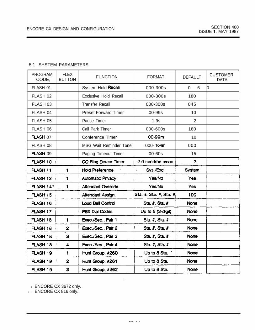
ENCORE CX DESIGN AND CONFIGURATION SECTION 400ISSUE MAY 1987
5.1 SYSTEM PARAMETERS
PROGRAM FLEX CUSTOMERCODE, BUTTON FUNCTION FORMAT DEFAULT DATA
FLASH 01 System Hold 000-300s 0 6 0
FLASH 02 Exclusive Hold Recall 000-300s 180
FLASH 03 Transfer Recall 000-300s 045
FLASH 04 Preset Forward Timer 00-99s 10
FLASH 05 Pause Timer 1-9s 2
FLASH 06 Call Park Timer 000-600s 180
07 Conference Timer 10
FLASH 08 MSG Wait Reminder Tone 000- 000
09 Paging Timeout Timer 00-60s 151
l ENCORE CX 3672 only.l l ENCORE CX 816 only.

SECTION 400ISSUE MAY 1987
ENCORE CX DESIGN AND CONFIGURATION
5.1 SYSTEM PARAMETERS (CONT’D)
CX 3872 only.l l Encore CX 818 only.
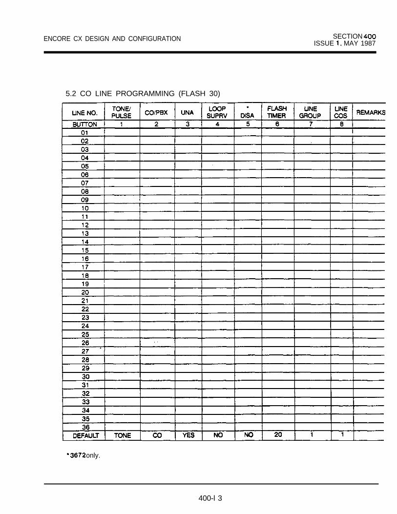
ENCORE CX DESIGN AND CONFIGURATION SECTION ISSUE MAY 1987
5.2 CO LINE PROGRAMMING (FLASH 30)
only.
400-l 3

SECTION 400ISSUE 1, MAY 1987
ENCORE CX DESIGN AND CONFIGURATION
5.3 STATION PROGRAMMING (FLASH 40)
DATA PAGE/ STATION NUMBER
FIELDD E F A U L T
P A G I N G Ail Yes
DND Yes
SYSTEM SPEED Yes
QUEUING Yes
RINGINGLINE ANSW
No
OHVA’ l No
CALL FWD Yes
ALARM SIGNAL’ No
STA ID 0
c o s
SPEAKERPHONE 0
PICKUP GRP(O-4)
1
PAGING ZONE 1(D-4)
PRE FWD(3 digits)
None
CO LINE GRP 1
ASSIGNMENTSee Button Assignment Chart Square* l l
l l l Square means that each button is assigned the corresponding line; ie. button 1 is line 1, etc.Page A is selected by pressing Button 10 of the flexible field.Page 8 is selected by pressing Button 11 of the flexible field.
l 816 only.l l 3672 only.

ENCORE CX DESIGN AND CONFIGURATION SECTION 400ISSUE MAY 1987
5.4 ASSIGNMENT CHART
This chart is to be used to assign CO line accessand ringing. Any button to be assigned as a CO lineneeds a numerical entry. as follows: ,
BB button assigned 01-24.00LL = line assigned Ol -36,OO
Ringing codes are:O-no ringing1 ringing2 -night ringing
and night ringing .
By default, buttons 1 are assigned as CO linesl-l 1 and button 12 as a loop key on the 3672.The remaining buttons on the phone areprogrammed as unused buttons by default.On the 816, buttons l-8 are CO lines l-8; the restwill be DSS buttons by default for stations 100 to103 ( 2 1 -button set), or- 1 0 0 to 1 1 5 sat).To unassign a button, enter the button number and 3pounds instead of the number:To assign a button as loop key, enter 00 for LL.When an SLT is being assigned to ring on an outsideline, enter 00 for BB one entry is necessarysince have no flexible buttons).l NOTE: Unassigned buttons can be programmed
by individual station users.
400-l 5

SECTION 400ISSUE MAY 1987
ENCORE CX DESIGN AND CONFIGURATION
5.4 ASSIGNMENT CHART (CONT’D) NUMBER I
24 I I I I

ENCORE DESIGN AND CONFIGURATION SECTION 400ISSUE MAY 1987
5.5 SYSTEM SPEED NUMBERS
Programmed from first attendant station.
Digits (up to 24)

SECTION 400ISSUE 1. MAY 1987
ENCORE CX DESIGN AND CONFIGURATION
i
5.6 EXCEPTION TABLES (FLASH 50)
ALLOW TABLE A (BTN 1)Digits (8 max.)
ALLOW TABLE 3)Digits (8 max.)
I 02 I0 2
0 3
04
0 3
0 4
0 5 06
0 7I 07 I08 0 8
0 9
10
09 I
17
18
19
2 0 I 20 I
DENY TABLE A (BTN 2)Digits (8 max.)
DENY TABLE B 4)Digits (8 max.)
01
0 2 I 02 I II 03 I0 3
0 4 I I I 05 I
06 06
I I I 07 I
10 I 10

ENCORE CX AND CONFIGURATION SECTION 400ISSUE 1, MAY 1987
5.7 SPECIAL TABLESSPECIAL TABLE 1 (BTN 5)
Area CodeOff ice Codes:
SPECIAL TABLE 3 (BTN
CodeOffice Codes:
SPECIAL TABLE 2 (BTN 6)
Area CodeOffice Codes:
Office Code+ 1 Code+O-Deny codes set by to deny)
SPECIAL TABLE 4 (BTN 8)
Home Area CodeOffice Codes:

l
SECTION ENCORE AND CONFIGURATION
6. FEATURE PACKAGE V
Feature Package V (FPS) software provides anumber of additional features to ENCORE CX system users. The following features are availableonly when Feature Package V software is installed onthe EPB.
7. UNIFORM CALL DISTRIBUTION (UCD)
As its name implies, the feature is a means ofuniformly distributing incoming calls among stationsin a group. Incoming CO calls, transferred CO callsand intercom calls can all be routed to a UCD group.
7.1 OPERATION
When a call is routed to a UCD group the system willsearch for an idle station, starting at the beginning ofthe group’s idle list. When an idle station is found,the system removes the station from the idle list andrings it. After the call is completed and released, thestation goes to the end of the group’s list.
Up to eight (8) groups can be configured in thesystem. Each group can contain up to eight (8)stations. A group is accessed via a number assigned to group. The pilot numbersand the corresponding groups are as fdlows:
7.2 CONDITIONS
Incoming CO
If all stations in a group are busy, COtine calls to ring for the UCD WaitAnswer period.
If the call remains unanswered at the end of that timethen the caller will receive a recordedannouncement, if assigned, for the specifiedmessage length time.
After receiving the announcement the call will beplaced on hdd for the specified message timer period and will hear Music On Hold.
If the call has not been answered at the end of themessage interval time then the call will receive therecorded announcement again and will again beplaced on hold.
The cycle continues until:1. the call is answered by a member of the UCD
group, or2. the overflow timer expires and the call is routed to
the overflow station.
NOTE: The timer starts when therecorded announcement is applied tothe call.
CO
CO that are transferred to a busy UCD group an ongoing cycle of Musk on Hold
(MOH), announcement, MOH, untilanswered or routed to the overflow station. Intercomcalls to a busy group receive busy tone.
a. A placed In DND is considered busy and isremoved from group’s list
b .
c. UCD groups can be together by
d. for a number.
considered busy.

ENCORE CX DESIGN AND SECTION
f.
h.
i.
k.
Four timers are applicable: ringer answer timer;recorded message length timer: message intervaltimer; and overflow timer.
A maximum of two announcement devices maybe assigned to the 8 groups. The first deviceis used to answer incoming CO The seconddevice is used to answer transferred and holdingco calls..
The overflow timer will not be started unless anoverflow station is in programming.
The overflow station cannot be a member of theUCD group.
To start the recorded announcement one of thefollowing must be used: an external device(connected to a trunk port) to detect loop current;or a ring start device connected to a SIB card.
If no device is assigned for recorded announce-ments then the answer timer will not be startedand calls to the UCD group will continue to ringuntil a member of the group available.Transferred CO calls hear Music On untilanswered.
Incoming CO lines assigned to the UCD groupmay be linked to a direct CO line or a loop buttonappearance.
REMOTE PROGRAMMING
Complete programming be done froma terminal. This allows changes to the database for feature and Changes can be made, the terminal, thesystem is being The terminal a I/Odevice connected to the port on the EPB.Access to this feature the use of thepassword “SMOKE’.
Certain buttons on the terminal compare to thebuttons on the telephone keypad that are normallyused to program the system on-site. See Figure 3.
T E R M I N A L
E N T E R F L E X 3 E
F L A S H , R
W I
FIGURE 3. EQUIVALENTS
Entering ? at prompt will display the“Remote Key Definitions” table.
VOICE MAIL
The voice mail feature autometlcelly handlesunanswered calls. be retrieved by .
users from the system wlth no the attendant. Up to eight (8) voice
be In the syetem. Eachgroup up to eight mail
number of

SECTION 400 ENCORE CX AND CONFIGURATION
9.1 INSTALLATION
An optionally system must beconnected to the ENCORE CX for this feature to beavailable. Voice mail be connected a SIB card. The number of voice mail stations isdependent upon hardware limitations of the ECXsystem (the number of available SIB ports) thevoice mail system.
A voice mail station can support a number of station users depending upon usage. Refer to theindividual voice mail system’s for therecommended of ports to station users(mailboxes).
9.2 OPERATION
Stations can forward calls to a voice group forleaving mail, or may call the voice mail group directlyto retrieve mail.
A voice mail group is accessed by dialing the pilotnumber assigned to that group. The numbersfor the voice mail groups are as
Transferred CO and can
idle stat&n at the group’s
removed from the list and it the station sands
tone& At the same thecalling station continues to ifthe call was forwarded to group (for
identifkation and communication the device.
When station ID is complete the audio connection ismade between the calling station and the voice station. When the call is released the system willreturn the voice station to the end of the group’slist and dial the appropriate digits (SO + sta tolight a message waiting indication.
And Canceling Indication
There are two methods by a ECX system usercan retrieve mail and cancel the messagewaiting indkatkn left by the mail system:
Method 1a.
b.
c.
The station user presses the flashing CALLBKbutton. The ECX system back the groupnumber of the voice system that left themessage waiting indicatkn. Once the voice mailsystem answers, the ECX system automaticallysends the DTMF digits of the extension callingback digits programmed in the assigned to the voke group. The digits(s)tells the system that the station user is .entering personal The ECXsystem then provides cut-through.The user listens to the voice system’s prompts and follows the instructionsprovided.
user exits his/her the ECXsystem cancels the messagewaiting
Method2
mailbox an off-premise oranother ECX station), the message
the ECX the the extension
accessed
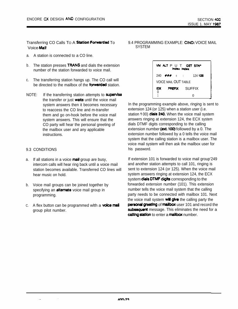
ENCORE DESIGN CONFIGURATION SECTION ISSUE 1. MAY
Transferring CO Calls TO A ToVoice
a. A station is connected to a CO line.
b. The station presses and dials the extensionnumber of the station forwarded to voice mail.
c. The transferring station hangs up. The CO call willbe directed to the mailbox of the station.
NOTE: If the transferring station attempts to the transfer or just until the voice mailsystem answers then it becomes necessaryto reaccess the CO line and m-transferthem and go on-hook before the voice mailsystem answers. This will ensure that theCO party will hear the personal greeting ofthe mailbox user and any applicableinstructions.
9.3 CONDITIONS
a.
b.
C.
If all stations in a voice group are busy,intercom calls will hear ring back until a voice mailstation becomes available. Transferred CO lines willhear music on hold.
Voice mail groups can be joined together byspecifying an voice mail group inprogramming.
A flex button can be programmed wlth a group pilot number.
9.4 PROGRAMMING EXAMPLE: VOICE MAILSYSTEM
P U T
240 0 1 124
VOICE MAIL OUT TABLE
SUFFIX01 0
In the programming example above, ringing is sent toextension 124 (or 125) when a station user (i.e.station 00) When the voice mail systemanswers ringing at extension 124, the ECX systemdials DTMF digits corresponding to the callingextension number followed by a 0. Theextension number followed by a 0 tells the voice mailsystem that the calling station is a mailbox user. Thevoice mail system will then ask the mailbox user forhis password.
If extension 101 is forwarded to voice mail group’249and another station attempts to call 101, ringing issent to extension 124 (or 125). When the voice mailsystem answers ringing at extension 124, the ECXsystem corresponding to theforwarded extension number (101). This extensionnumber tells the voice mail system that the callingparty needs to be connected with mailbox 101. Nextthe voice mall system the calling party the
of user 101 and record the message. This eliminates the need for a
to enter a number.
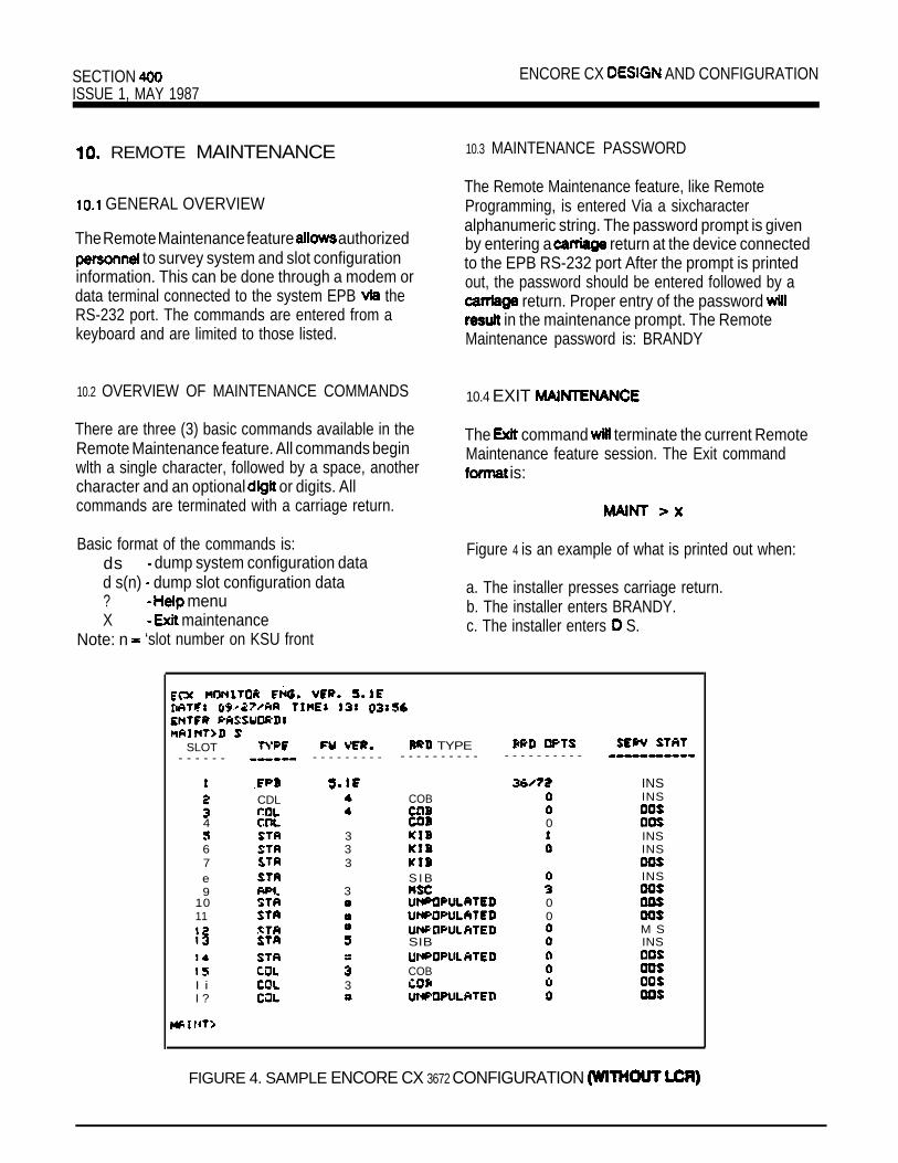
SECTION ENCORE CX AND CONFIGURATIONISSUE 1, MAY 1987
REMOTE MAINTENANCE
GENERAL OVERVIEW
The Remote Maintenance feature authorized to survey system and slot configuration
information. This can be done through a modem ordata terminal connected to the system EPB theRS-232 port. The commands are entered from akeyboard and are limited to those listed.
10.3 MAINTENANCE PASSWORD
The Remote Maintenance feature, like RemoteProgramming, is entered Via a sixcharacteralphanumeric string. The password prompt is givenby entering a return at the device connectedto the EPB RS-232 port After the prompt is printedout, the password should be entered followed by a
return. Proper entry of the password in the maintenance prompt. The Remote
Maintenance password is: BRANDY
10.2 OVERVIEW OF MAINTENANCE COMMANDS
There are three (3) basic commands available in theRemote Maintenance feature. All commands beginwlth a single character, followed by a space, anothercharacter and an optional or digits. All
10.4 EXIT
The command terminate the current RemoteMaintenance feature session. The Exit command
is:
commands are terminated with a carriage return.
Basic format of the commands is:ds dump system configuration datad s(n) dump slot configuration data? menuX maintenance
Note: n ‘slot number on KSU front
Figure 4 is an example of what is printed out when:
a. The installer presses carriage return.b. The installer enters BRANDY.c. The installer enters S.
SLOT TYPE - - - - - - - - - - - - - - - - - - - - - - - - - - - - - - - - - - -
4
67e9
1011
I iI ?
CDL
333
3
3
INSCOB INS
01 INS
INS
S I B INS
00
M SSIB INS
COB
FIGURE 4. SAMPLE ENCORE CX 3672 CONFIGURATION

ENCORE CX DESIGN AND CONFIGURATION SECTION 400ISSUE 1. MAY 1987
Figure 4 is a configuration of a 3672 system withoutLCR, where:
Column 1 lists the card slot.Column 2 lists card type of that card
slot.Column 3 lists the firmware version of the
card.Column lists card type and if that card
is installed.Column 5 lists card options:
APL option 0 = standard APLAPL option 1 APL + APL option 2 APL + RSMAPL option 3 APL + + RSM
Column 6 lists card status:means not present or switchedout of on card
INS means present and
5 is an example of a configuration for a 36112 option 0 standard
KIB option 1 OHVA system with LCR.
TIME:
ENTER
SLOT TYPE TYPE OPTS SERV STAT - - - - - - - - - - - - - - - - - - - - - - - - - - - - - - - - - - -
EFB44
4
. . 37 3
9
11 ::12 14 ::
3 3
INSCOB INSCOBCOB 0KIB 1KIB 1 INSK I R 0SIBMSC
INS
UNPOPULATED0
UNPOPULATED 0UNPOPULATEDUNFOPULRTED 0 00s
0UNPOPULATED 0
UNPOPULATED 0UNPOPULATED 0 00s
00sUNPOPULATEDCOB 0COB 0
00s
DATE: 14 : 13 UTIL ITY. . .
FIGURE S SAMPLE ENCORE CX CONFIGURATION (WITH LCR)
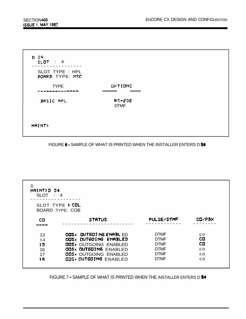
SECTION ENCORE CX DESIGN AND CONFIGURATION
: 4
- - - - - - - - - - - - - - - - -SLOT TYPE : HPL
TYPE:
TYPE
DTMF
FIGURE SAMPLE OF WHAT IS PRINTED WHEN THE INSTALLER ENTERS D
D
SLOT : 4- - - - - - - - - - - - - - - - -
SLOT TYPE BOARD TYPE: COB
- - - - - - - - - - - - - - - - - - - - - - - -
13 ED14
OUTGOING ENABLED16 ENABLED17 OUTGOING ENABLED
ENABLED
- - - - - - - - - - - - - - - - - - - -
DTMF coDTMFDTMFDTMF coDTMF coDTMF co
FIGURE 7 SAMPLE OF WHAT IS PRINTED WHEN THE INSTALLER ENTERS D

ENCORE CX DESIGN AND CONFIGURATION SECTION
:
: TYPE:
TYPE STATUS LCD- - - - - - - - - - - - - - - - - - - - - - - - -
INSI INS
INS
INS
2 4 N
NN
N
Column 1Column 2Column 3
Column 4Column
FIGURE 8 SAMPLE OF WHAT IS PRINTED WHEN THE INSTALLER ENTERS
indicates station number. station type DSS, phone box).
indicates status: status can indicate the entire card is out of service or a station is not installed or
installed but not operational.INS status can Is and operating correctly.indicates s&e.indicates display at set.

SECTION ENCORE CX DESIGN AND CONFIGURATION
- - - - - - - - - - - - - - - - - - - - - - - - - - - - - - - - - - - - - - - - - - - -
PULSEDTMFDTMF
PBXCOCOCOCOCO
NT>
FIGURE 9 SAMPLE OF WHAT IS WHEN THE INSTALLER ENTERS
Column 1 denotes Central Office line number (l-36)Column 2 denotes card in service or out of and CO line for outgoing by the attendant or
availableColumn 3 denotes dialing typeColumn 4 denotes line type
? L I S T :
SYSTEM OR SLOT A N
NO INDICATES THE ENTIRE SYSTEM BE DUMPE
S ENTIRE SYSTEM S 2 <DUMPS SLOT 2 ETC.>
? HELP MENUX E X I T
FIGURE’10 SAMPLE OF WHAT IS PRINTED WHEN THE INSTALLER ENTERS
.
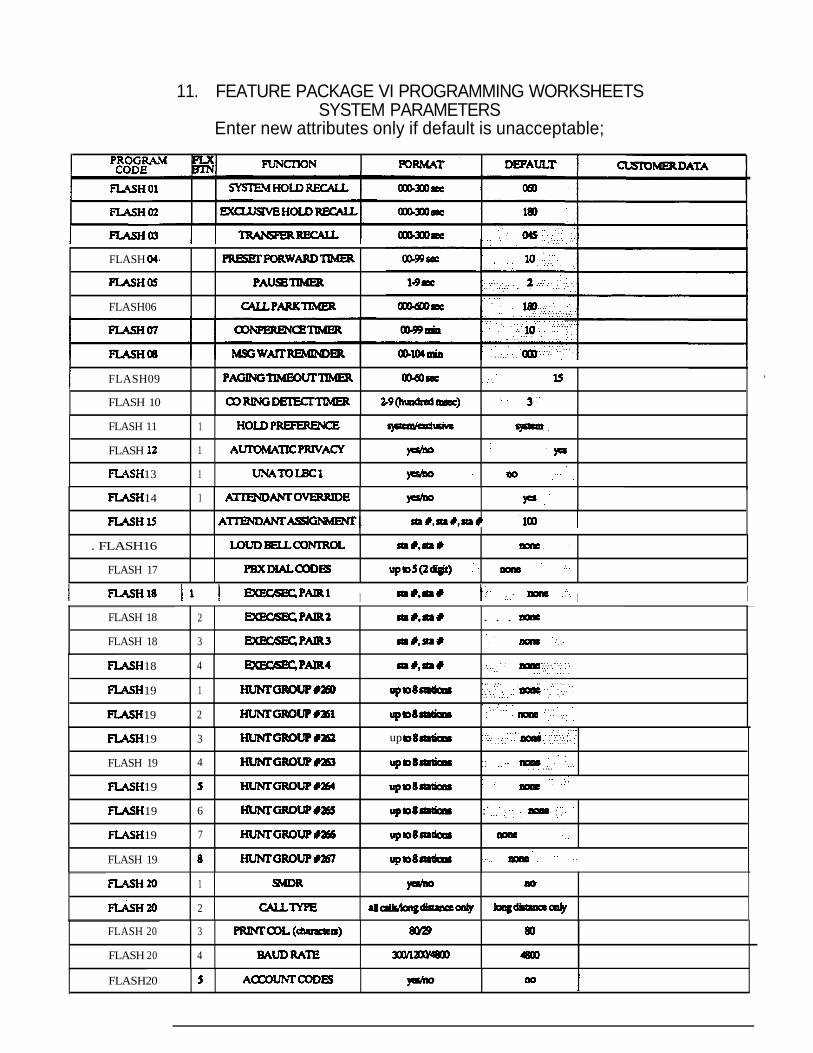
11. FEATURE PACKAGE VI PROGRAMMING WORKSHEETSSYSTEM PARAMETERS
Enter new attributes only if default is unacceptable;
FLASH
FLASH06
FLASH09 ,
FLASH 10
FLASH 11 1
FLASH 1
13 1
14 1
. FLASH16
FLASH 17
I 1 IFLASH 18
FLASH 18
2 . . .
3
18
19
19
4
1.
2
19 3 up
FLASH 19 4
19
19 6 :
19 7
FLASH 19
1
2
FLASH 20 3
FLASH 20 4
FLASH20
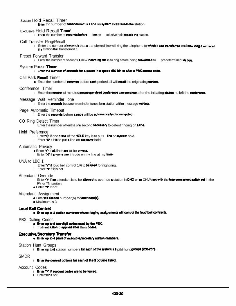
System Hold Recall Timerl thr number of on hold station.
Exclusive Hold Recall l the number of l on l xolusive hold station.
Call Transfer Ring/Recalll Enter the number of that transferred line will ring the telephone to it end
station transferred it.
Preset Forward Transferl Enter the number of seoonds new is to ring before being to l predetermined
System Pause l
Call Park TimerEnter the number of before perked ail wiii the originating
Conference Timerl Enter the of minutes after the initiating hu left the
Message Wait Reminder lonel Enter the between reminder tones for station with message
Page Automatic Timeoutl Enter the before will be
CO Ring Detect Timerl Enter the number of tenths of second to deteot ringing on
Hold Preferencel Enter if one of the key is to put l on hold.l Enter if it to put line on hold.
Automatic Privacy Enter if liner to be
l Enter if intrude on my line at my
UNA to LBC 1l Enter if loud bell control 1 to for night ring.l Enter if it is not.
Attendant Overridel Enter if attendant is to be to override station in or OHVA the in the
PV or TN position. Enter if not.
Attendant Assignment Enter number(a) for Maximum is 3.
PBX Dialing Codes
l Toll b then
Station Hunt Groupsl up to station numbers pibt hunt
SMDRl
Account Codesl l Enter if not.

FEATURE PACKAGE VI (183296112)SYSTEM PARAMETERS
Enter new attributes only if default is unacceptable
D E F A U L T
F L A S H 3 6 2 .F L A S H 3 6 3
F L A S H 3 6 4
F L A S H 3 6
F L A S H 3 6 6
7
G R O U P 2 7 2

. if ration is to or . if to 10 l technician.
LCR Enable. l o l n8bb LCA . LCR features.
Security Access Code. digit which must by on to gain to
DTMF.
Intercom Box Ring TimerEnter number of station will ring any box button.
Dedicated Attendant Intercom if path is to to
not.
Music Selectl is to with background musk .
l if is to be no background
Time sot at of installation.
Group Listening Enable mode)l to l nablo station to on Monitor to l Enter to
Hook Switch Timerl number of of a to long sot must in for it to
flash.
Hook Switch Bounce l Entor thr numkr of of to valid on-hook or off-hook from 2500
Attendant Recall Timerl Entor numkr of call will attendant being by
Tone allow Pago
Additional Intercom l l l N’ additional l This last COB cud slot of COB cud b
UCD-Ring Answerl
UCD-Music l
UCD-Overflowl
Auto Save
Hold
Timerl
wud designated

FEATURE PACKAGE VI (1632486112)SYSTEM PARAMETERS
Enter new attributes only if default is unacceptable
I I DATA I
43 6
FLASH 43
FLASH 43 8
FLASH44 VOICE
RASH45 OR3 3
RASH 51 2
FLASH 51 3
FLASH 4
FLASH 51 6
7

Announce for no CM tom.
l E n t e r l for 1 tone burst tone.l for 3 tone burst
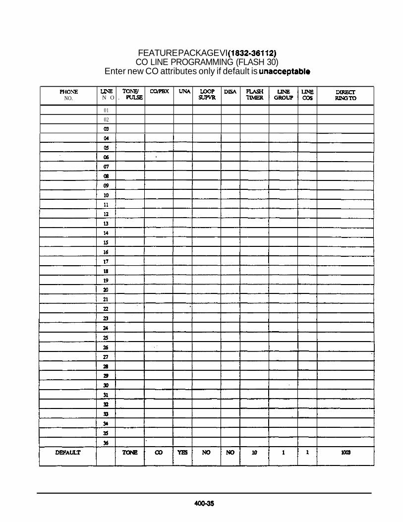
FEATURE PACKAGE VI CO LINE PROGRAMMING (FLASH 30)
Enter new CO attributes only if default is
NO.
N O .
01
02

Phone Number. 7 digit circuit . in all to right for that
Tone/Pulsel if the line is to send . if dial.
l Enter if is to (this WATS,
Universal Night Answer (UNA)l if is to by dialing at night.l
Loop Supewisionl to with thr ability to loop current no
in use.l Enter if it is not
l if thr is to a line 24 day.Enter if me line is to be l at night only.Enter if it not to be a line.
(Maximum of 3 liner per
Flash Timerl Enter the number of tenths of press of PUSH key is to l to 2
CO Line Group
.
l l Enter if to be in a group that by dialing l group dial ‘81’.l group dial l ‘4’ group dial l group dial l group dial l group dial
CO Class of ServiceEnter if no restrictions to to
l if me is to governed by A station of 2 and 4.l
Direct Ring Enter UCD group
or
of
1) and or

FEATURE PACKAGE VI (1832036112)STATION PROGRAMMING (FLASH 40)
Enter new attributes only default is unacceptable
PAGING
NOA A -
NO
ADD-ON NO

Station Type. 2 1 1 2 buttons 9 function bunons.. above with LCD l 2 4 buttons 9 function buttons.l with LCD display.l Select.l box with 2 buttons (DND and
Cable Number this
Dial Page Accessl if a station is have paging station is not to be
DND Access l ii station is permitted to Not not, enter ‘no’.
System Speed Dial Accessl if station is permitted to have to system speed dial numbers, enter If not, enter
Trunk Queue Accessl if station is to for busy group of l ntsr l not, enter
Ringing Line Preferencel if a station automatically ringing by going
not. l ntor
Off-Hook Voice Announcel if station is to be to If not,
SLT Add-On Conference Disablel if SLT station is denied if enter .
Call Accessl station is permitted to enter l not,
LCR Class of Service Priorityl a 1 and I; 1 being the priority.l if LCR COS is to or in list table, that group is
Station Identificationl of the following:
0 line 2 3 8 4 box
l NOTE: l NOTE l 2 first bs l is background
Station Class of l
3 4 6
Speakerphone/Headset Operation
1 2 disabled operation)
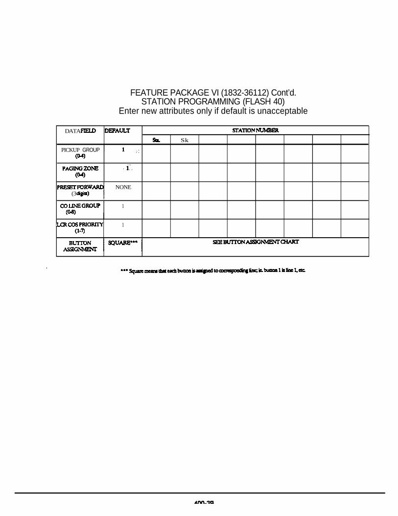
FEATURE PACKAGE VI (1832-36112) Cont’d.STATION PROGRAMMING (FLASH 40)
Enter new attributes only if default is unacceptable
DATA
Sk
PICKUP GROUP
NONE(3
1
1

Call Pickup Groupl pickup group . station is not in pickup group
Zone Page Groupl page tones station will . station will not
Preset l station to which now incoming which will forward. Timor for is
Dial Line Group Accessl Enter the groups to station to dial
1 dial 2 3 82 4 dial 5 dial 84 8 dial 7 dial 8 dial +

FEATURE PACKAGE VI (1832036112) ASSIGNMENT CHART
Enter new attributes only if default is unacceptable
1
10
11
14
ONBACKOFPAGE

By default buttons l-1 1 are assigned as CO lines 1 and button 12 as a loop key. The remaining buttons on the phone are unassigned.
To unassign a button (remove the CO line programming), enter the button number when programmingand 2 pounds
To assign a button as a loop key, enter 00 for line number.
EXAMPLE
36112 Default
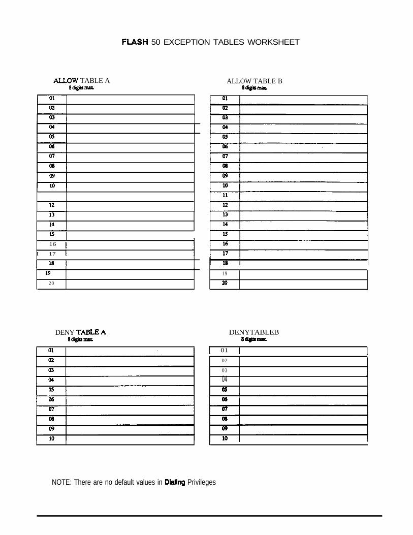
50 EXCEPTION TABLES WORKSHEET
TABLE A ALLOW TABLE B
16
I 17
20
DENY
1 9
DENYTABLEB
01 102
03 J04
NOTE: There are no default values in Privileges

Should the customer special exceptions to unrestricted, restricted and/Or intercom Only of service,the information should be input on the Dialing form.
To “customize” dialing privileges, enter from one to eight digits in the Allow column (e.g., 69299622) and/or one toeight digits in the Deny (e.g. 0 and 1). You may Specify up to 20 8digit allow entries and up to 10 denyentries in each table. If you do not have enough entries on this form for your customer’s special dialing needs, seeyour Operations Manager for assistance.
The following entries are samples of a customer’s dialing who wishes to accomplish the following:
ALLOWcalls to l-896calls to Calls to area code 305Calls to area 704
to Calls to 494441 exchangeLocal calls
DENY (0 + and dialing)
976 calls
411 calls
SAMPLE
TABLE A ALLOW TABLE A DENY
1. l-8902. l-5553.3054. 7645. 6.4944417.8.9.10.11.12.13.14.15.16.17.18.19.20.
1.9762.411
4.0 1
6.7.8.9.10.

UCD GROUPS
Alternate Group Table
NOTE: A call will not be transferred to an ovefflow station unless an announcement has been programmed. An overflow stationcannot be part of a UCD, voice mail or hunt group.

l Refer to system programming for UCD timers.
Alternate l Of which if in origin& group
Overflow Station Enter station for station is to This station cannot a of
l NOTE: This will not sot and RAN programmed.
S t a t i o n sl a miximum of 8 station
Announcement Tablel Y if RAN to be If not.
Announcement Table (RAN)
l must l ithof CO port or pott
index is CO port
l is
l imel Value entered depends on of on

LEAST COST ROUTING
1.
2.
3.
4.
5.
6.
7.
8.
9.
Does customer have more than one carrier?
If yes, which
Is customer using access?
Who is the equal access carrier?
(If customer doesn’t know, you may l-700-55541 41 to find out carrier for each individual line.)
Does customer dial international calls?
Does the customer have FX lines?
Fx to from
Fxto from
How does customer dial FX
Does customer have WATS lines?
Band 1 (quantity)
Band 2 (quantity)
Band 3 (quantity)
Band 4 (quantity)
Band (quantity)
area code
area code
offlce code
offlce code
Does customer have a 24 hour operation?
Does customer operate on weekends?
Does customer diai for long distance
10. Are there any local long distance exchanges the customer wants to allow or
Will lines be a choke in any route?
12. Are there any to, be to local lines?
VOICE MAIL
Does the customer to have a voice system?
if so, how many ports?

SECTION 401KEY TELEPHONE SYSTEM ISSUE FEBRUARY 1988
LEAST COST ROUTING (LCR)
TABLE OF CONTENTS
1.
2
3.
4.
5.
6.
9.
10.
11.
1.2.3.4.5.6.7.8.9.1 0 .
INTRODUCTION . . . . . . . . . . . . . . . . . . . . . . . . . . . . . . . . . . . . . . . . . . . . . . . .
ENHANCED PROCESSOR BOARD (2994402) ANDLCR (2996301). . . . . . . . . . . . . . . . . . . . . . . . . . . . . . . . . . . . . . . .
FEATURES CHARACTERISTICS . . . . . . . . . . . . . . . . . . . . . . . . . . . . . . . . .
ROUTE LIST TABLE . . . . . . . . . . . . . . . . . . . . . . . . . . . . . . . . . . . . . . . . . . . . . .
TIME OF DAY ROUTING . . . . . . . . . . . . . . . . . . . . . . . . . . . . . . . . . . . . . . . . . .
INSERT/DELETE TABLES . . . . . . . . . . . . . . . . . . . . . . . . . . . . . . . . . . . . . . . . . 2
EXCEPTION TABLE .. . . . . . . . . . . . . . . . . . . . . . . . . . . . . . . . . . . . . . . . . . . . . . 2
T. TABLE . . . . . . . . . . . . . . . . . . . . . . . . . . . . . . . . . . . . . . . . . . . . . . . . . . 2
TABLE (OFFICE CODES) . . . . . . . . . . . . . . . . . . . . . . . . . . . . . . . . . . 3
OPERATION . . . . . . . . . . . . . . . . . . . . . . . . . . . . . . . . . . . . . . . . . . . . . . . . . . . . . . . 3
WORKSHEETS. . . . . . . . . . . . . . . . . . . . . . . . . . . . . . . . . . . . . 4
LIST OF FIGURES
ROUTE LIST TABLE. . . . . . . . . . . . . . . . . . . . . . . . . . . . . . . . . . . . . . . . . . . . . . . . 5CO GROUPS. . . . . . . . . . . . . . . . . . . . . . . . . . . . . . . . . . . . . . . . . . . . . . . . . 7DAILY TIME TABLE. . . . . . . . . . . . . . . . . . . . . . . . . . . . . . . . . . . . . . . . . . 7WEEKLY SCHEDULE TABLE . . . . . . . . . . . . . . . . . . . . . . . . . . . . . . . . . . . . . . . . 8EXCEPTION TABLE. . . . . . . . . . . . . . . . . . . . . . . . . . . . . . . . . . . . . . . . . . . . . . . . 8INSERT/DELETE TABLES . . . . . . . . . . . . . . . . . . . . . . . . . . . . . . . . . . . . . . . . . . . 9
TABLE . . . . . . . . . . . . . . . . . . . . . . . . . . . . . . . . . . . . . . . . . . . . . . . . . .6-DIGIT OFFICE CODE TABLE . . . . . . . . . . . . . . . . . . . . . . . . . . . . . . . . . . .LCR OPERATION FLOWCHART. . . . . . . . . . . . . . . . . . . . . . . . . . . . . . . . . . . . .PRINTING LCR TABLES . . . . . . . . . . . . . . . . . . . . . . . . . . . . . . . . . . . . . . . . . . .

ENCORE CX 3672 SECTION 401KEY TELEPHONE SYSTEM ISSUE 1, FEBRUARY 1988
LEAST COST ROUTING (LCR)
1. INTRODUCTIONThe ENCORE CX Least Cost Routing (LCR) featureis a cost-saving enhancement which selects themost economical programmed route for an outgoingcall. When a station user dials an outside number,the LCR feature analyzes the number and thenautomatically chooses an outside line from the groupthat has been programmed as least costly.
LCR feature puts the responsibility of choosingthe least expensive route for each area code andexchange code on the system, not on the stationuser.
2. ENHANCED PROCESSOR BOARD(2994402) AND LCR SOFTWARE(2996301)
In order to have access to the LCR feature,the ENCORE CX 3672 KSU must be equipped withan EPB (Enhanced Processor Board) card that has LCR software (2996301) installed.The card replaces the Central Processor Board(CPB) in the KSU, and is inserted in the samecard slot.
The EPB is shipped without software.The software enabling 3872. LCR is a PROM chip setthat is installed on the EPB.
3. FEATURES CHARACTERISTICSIn order to make the routing decision; the ENCORECX LCR feature uses a ‘data base. data base isprogrammed by field personnel at the time ofinstallation. The operation of the feature is completely upon the accuracyof the programming.7 different tables are set up to monitor the dialingof digits and to select the best route for the calldepending on time of day. The tables are:
1. Route List Table2. Daily Start Time Table3. Weekly Schedule Table4. Insert/Delete Table5. Exception Table6. Table7. Office Code Table.
4. ROUTE LIST TABLEUp to 16 different routes can beprogrammed. Each route can contain up to 4 routelists one for each of the 4 time periods. Up to 7CO line groups (routing choices) and theircorresponding Insert/Delete Tables may beprogrammed within each route list. Route ListTable should be programmed in sequence so thatthe first line group entry is the least costly(and first selected) and the last CO line group is themost costly (and last selected). (See Figures
. &
5. TIME OF DAY ROUTINGThe least costly route for a particular dialed numbermay be different at different times of the day and ondifferent days of the week. To accommodate thissituation, there are 2 time-of-day tables (Daily StartTime Table and Weekly Schedule Table). These tableswork together to:A. Dii each day into 1-4 time periods, andB. Specify the list number to be used for all routes
based on the time of day and day of week.By default, the Daily Start Time is set at thestandard diisions of 8 AM, 5 PM and 11 PM.In addition, the route lists specified by the WeeklySchedule are consistent with the InterstateDDD discount structures for those time periods.However, both tables can be changed depending
customer requirements. (See Figures 3

SECTION 401 ENCORE CX 3672 LEAST COST ROUTING 1. FEBRUARY 1988
6. INSERT/DELETE TABLESThere are 20 Insert/Delete Tables (00-l 9).Up to twenty digits, including pauses, can be insertedand up to sixteen digits deleted. Digits can beinserted before or after the number dialed, but canbe deleted only from the beginning of a numberdialed.For instance, if a user dials a long distance callthat should be placed on a home area code foreignexchange line, the digit dialed by the usermust be deleted before the call is placed on that line. Insert/Delete Table can be programmed todo this. Digits can also be added to a number thathas been dialed by the user. access codes,for instance, can be automatically inserted by thesystem. (See Figures 61 to
7. EXCEPTION TABLE table is used to route operator assisted calls any other calls which would use a 1 or
number rather than a 3-digit area code.There are 20 available entries in this table.Each entry contains both the exception code (1 or 2digits) and the two-digit route number (00-l 5) to beused for that code. (See Figure 5) There are nodefault data entries in the Exception Table.CAUTION: The Dialing Privileges tables are not
checked for any calls routed via theException Table.
8. DIGIT TABLEThis table is divided into 2 sections: “Leading
is dialed before the and “Non Leading (no is dialed before the number). This gives
the system the ability to handle call routing in areasthat require a before a long distance number,as well as in areas that do not require the
This table provides routing based on the first threedigits of the number dialed including: area codes;service Codes such as 911,411, etc.; office codesfor the home NPA and direct International dialaccess It should also include, for each 3digitcode, the route to be used, the number of digits likelyto be dialed and if the Table is to be checked.
table can include 1000 entries from (See Figure
CAUTION: All local office codes must beincluded in this table or local callscannot be completed through LCR.
The number of digits likely to be dialed controlsrouting of calls as follows:A. Fewer than the programmed number of digits
dialed:The system pauses seconds after the last digit isdialed before routing.B. Exactly the programmed number of digits dialed:.The system routes the call as soon as it sees thelast digit it is programmed to expect.C. More than the programmed number of digits
dialed:System routes the call as soon as sees the lastdigit it is programmed to expect, ignores alldigits in excess of the programmed number.NOTE: A minimum of 3 digits is required for route
selection by the Table. the has routed the call and sent all
digits, the keypad is live and digits canbe if required.A default table been established for area codes,and for both the “Leading and “Non Leading sections of the for service codes andoffice codes associated with the home
refer to the LCR default data fordetailed information. See Exhibit I for the DefaultData Base.
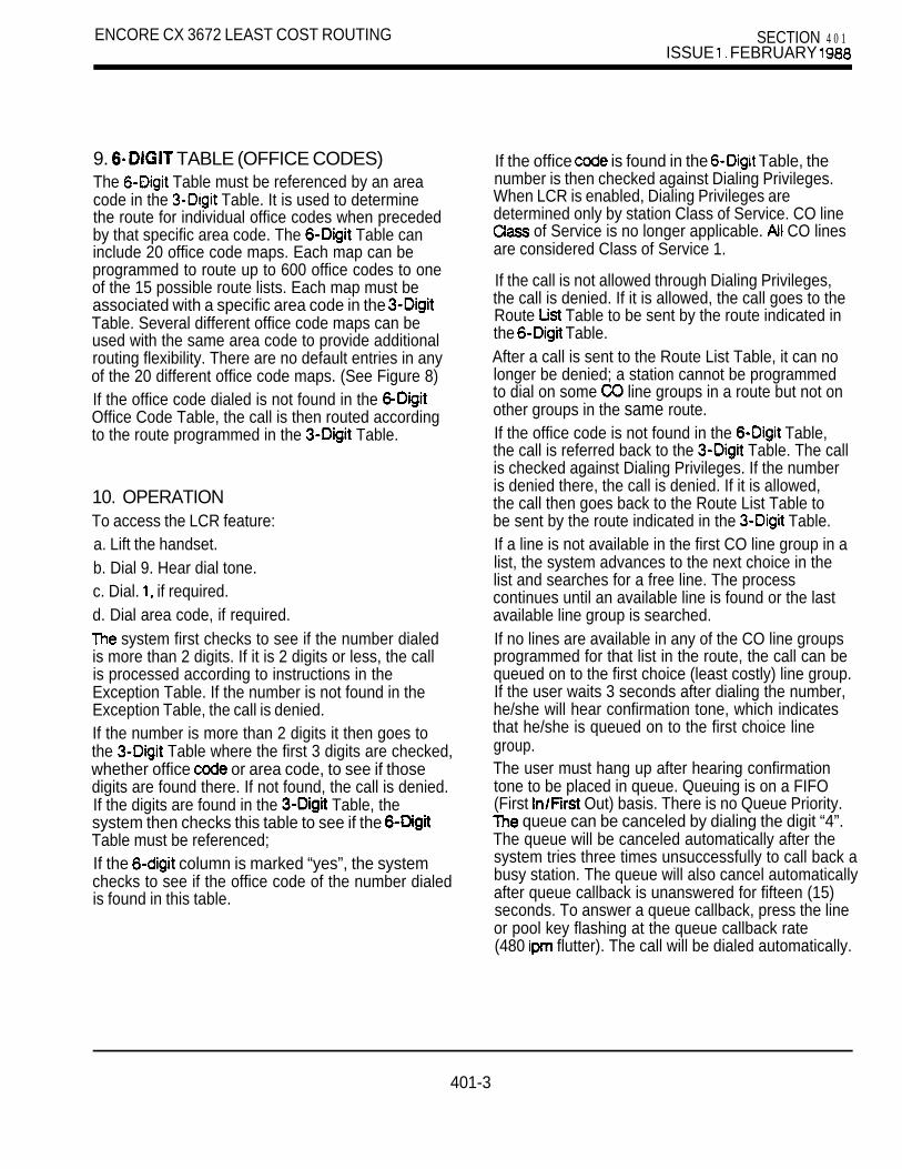
ENCORE CX 3672 LEAST COST ROUTING SECTION 4 0 1ISSUE FEBRUARY
9. TABLE (OFFICE CODES)The Table must be referenced by an areacode in the Table. It is used to determinethe route for individual office codes when precededby that specific area code. The Table caninclude 20 office code maps. Each map can beprogrammed to route up to 600 office codes to oneof the 15 possible route lists. Each map must beassociated with a specific area code in the Table. Several different office code maps can beused with the same area code to provide additionalrouting flexibility. There are no default entries in anyof the 20 different office code maps. (See Figure 8)If the office code dialed is not found in the Office Code Table, the call is then routed accordingto the route programmed in the Table.
10. OPERATIONTo access the LCR feature:a. Lift the handset.b. Dial 9. Hear dial tone.c. Dial. if required.d. Dial area code, if required.
system first checks to see if the number dialedis more than 2 digits. If it is 2 digits or less, the callis processed according to instructions in theException Table. If the number is not found in theException Table, the call is denied.If the number is more than 2 digits it then goes tothe Table where the first 3 digits are checked,whether office or area code, to see if thosedigits are found there. If not found, the call is denied.If the digits are found in the Table, thesystem then checks this table to see if the Table must be referenced;If the column is marked “yes”, the systemchecks to see if the office code of the number dialedis found in this table.
If the office is found in the Table, thenumber is then checked against Dialing Privileges.When LCR is enabled, Dialing Privileges aredetermined only by station Class of Service. CO line
of Service is no longer applicable. CO linesare considered Class of Service 1.
If the call is not allowed through Dialing Privileges,the call is denied. If it is allowed, the call goes to theRoute Table to be sent by the route indicated inthe Table.After a call is sent to the Route List Table, it can nolonger be denied; a station cannot be programmedto dial on some line groups in a route but not onother groups in the same route.If the office code is not found in the Table,the call is referred back to the Table. The callis checked against Dialing Privileges. If the numberis denied there, the call is denied. If it is allowed,the call then goes back to the Route List Table tobe sent by the route indicated in the Table.If a line is not available in the first CO line group in alist, the system advances to the next choice in thelist and searches for a free line. The processcontinues until an available line is found or the lastavailable line group is searched.If no lines are available in any of the CO line groupsprogrammed for that list in the route, the call can bequeued on to the first choice (least costly) line group.If the user waits 3 seconds after dialing the number,he/she will hear confirmation tone, which indicatesthat he/she is queued on to the first choice linegroup.The user must hang up after hearing confirmationtone to be placed in queue. Queuing is on a FIFO(First Out) basis. There is no Queue Priority.
queue can be canceled by dialing the digit “4”.The queue will be canceled automatically after thesystem tries three times unsuccessfully to call back abusy station. The queue will also cancel automaticallyafter queue callback is unanswered for fifteen (15)seconds. To answer a queue callback, press the lineor pool key flashing at the queue callback rate(480 flutter). The call will be dialed automatically.
401-3

SECTION 401ISSUE FEBRUARY
ENCORE CX 3672 LEAST COST ROUTING
10.1 CO LINE GROUP ACCESSRestrictions in a system with LCR apply only when astation attempts to access a line in a group througha direct key appearance of that line or by dialingthe Trunk Group Access Code. A station is notrestricted from access to a line group if that groupis part of a route which is accessed by the stationvia the LCR feature access code (dial This istrue regardless of whether or not LCR access isforced in the system.See Figure 9 for an LCR operation flow chart.
11. WORKSHEETSIt is extremely important that the worksheets becompleted before programming the LCR tables.
It is suggested that the worksheets be completed inthe following order. First fill out the CO line grouptable, then the Exception Table (as this is the firsttable the system will check when a number is dialed).Then determine time of day routing by completingboth the Daily Start Time Table and the WeeklySchedule Table. These times are used in the RouteList Table. Next determine time and line grouppriority for the various routes to be used.
complete the Insert/Delete Table and, using thistable, complete the last column in the Route List
When the Route List Table has been completed,then fill out the Table. Area codes can bebroken into specific office codes by using the
Table. Refer to Figure 9 for a flow chart onthe operation of LCR.
401-4

ENCORE CX 3672 LEAST COST ROUTING SECTION 401ISSUE 1988
ROUTE TIME C O CO INS/ COCHC DEL CHC DEL CHC DEL CHC DEL CHC DEL CHC DEL CHC DEL
1 2 3 4 7
I
0 0
I I
01
KEY: CHC ChoiceKEY: CHC Choice
ROUTE LIST TABLEROUTE LIST TABLEFIGURE l-1FIGURE l-1
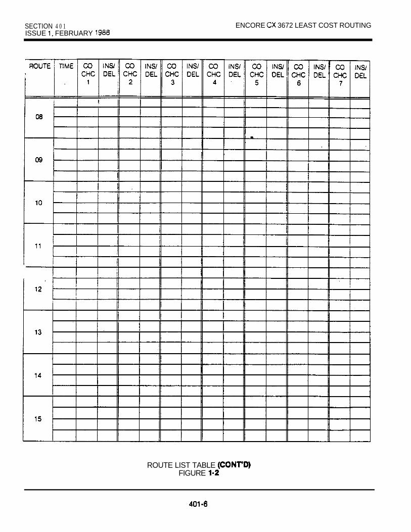
SECTION 4 0 1 ENCORE 3672 LEAST COST ROUTINGISSUE FEBRUARY
ROUTE LIST TABLE FIGURE

ENCORE CX 3672 LEAST COST ROUTING SECTION-401ISSUE 1. FEBRUARY 1988
2 3 4 5 6 7
Enter what type lines are programmed in each group.
CO LINE GROUPSFIGURE 2
TABLE DEFAULTTIME CHANGED TIME
1
2
3
4
DAILY START TABLEFIGURE 3
401-7

SECTION 401 ENCORE 3672 LEAST C O S T ROUTINGISSUE 1. FEBRUARY
M T W T F S S
2. (17:00) --a---------------
3. ------------B-m---
4.
table is set up with default programming.
WEEKLY SCHEDULE TABLEFIGURE 4
CODE
ROUTE
TABLE
401-8

ENCORE CX 3672 LEAST COST ROUTING SECTION 401ISSUE 1. FEBRUARY 1988
TABLE DIGITS DIALED
00INSERT
PRE
POST
DELETE (PAE)
01INSERT
PRE
POST
DELETE (PRE)
02
PREINSERT
POST
DELETE (PRE)
PREINSERT
03 POST
DELETE (PRE)
04INSERT
PRE
POST
DELETE (PRE)
05INSERT
PRE
DELETE (PRE)
06
PRE
DELETE
TABLESFIGURE
401-Q
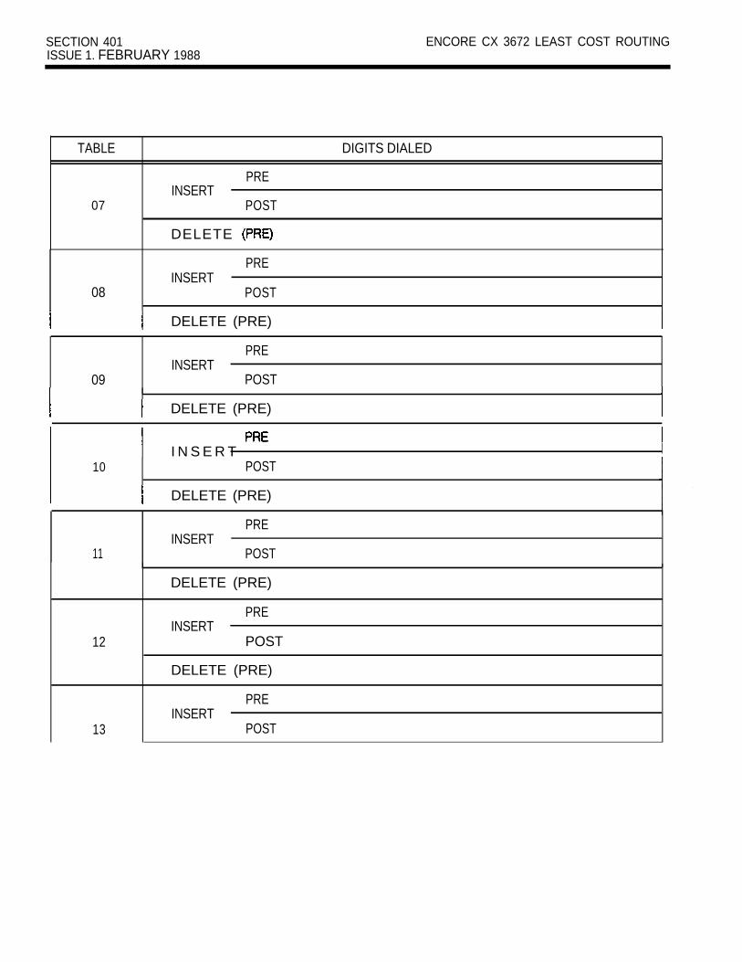
SECTION 401 ENCORE CX 3672 LEAST COST ROUTINGISSUE 1. FEBRUARY 1988
TABLE
07
PREINSERT
POST
DELETE
DIGITS DIALED
08INSERT
PRE
POST
DELETE (PRE)
09INSERT
PRE
POST
DELETE (PRE)
I N S E R T10 POST
DELETE (PRE)
11INSERT
PRE
POST
DELETE (PRE)
12
PREINSERT
POST
DELETE (PRE)
13
PREINSERT
POST

ENCORE CX 3672 LEAST COST ROUTING SECTION 4 0 1ISSUE 1, FEBRUARY 1988
TABLE
1 4
15
PREINSERT
POST
DELETE (PRE)
PREINSERT
POST
DELETE (PRE)
DIGITS DIALED
PRE I INSERT I
16 POST
DELETE (PRE) I
PRE INSERT
17 I POST
DELETE (PRE) . .
P R EINSERT
18 I POST
I DELETE (PRE) I
INSERT19
DELETE (PRE)
INSERT/DELETE TABLES (CONT’D)FIGURE
4 0 1 - 1 1

SECTION 401 FEBRUARY 1988
ENCORE CX 3672 LEAST COST ROUTING
CODE
LEADING 1 NON-LEADING 1 is dialed) is not dialed)
RR 6 PP RR 6 PPI I
II
I I II I II I II I II I I
II I II I
I I I
I I III
I II I
I II I
II
II
I II
I I I II I
I II I I
I III I
II
I I II
II I I
III II I
I II I
I II I II I I III I I
I II I
I I II I II I III I
II III I I II
RR = Refers to route list in the route list table;PP = Maximum no. of digits likely to be dialed;6 = Refers to table (Y/N).
TABLEFIGURE 7
401-l 2

ENCORE CX 3672 LEAST COST ROUTING SECTION 401ISSUE FEBRUARY 1988
AREA RTE NO. AREA RTE NO. AREA RTE NO. AREA RTE NO. AREA RTE NO.CODE CODE CODE CODE
OFFICE CODES OFFICE CODES OFFICE CODES OFFICE CODES OFFICE CODES
OFFICE CODE TABLEFIGURE
401-13
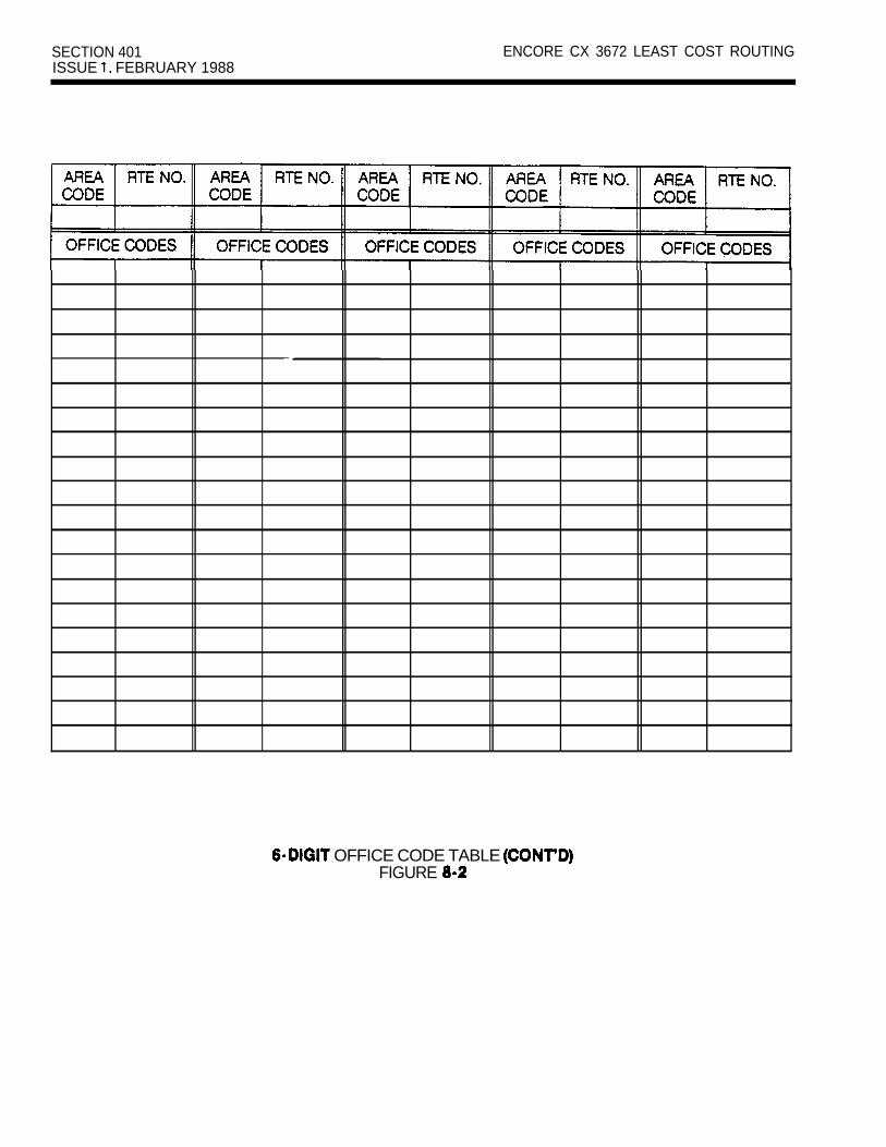
SECTION 401ISSUE FEBRUARY 1988
ENCORE CX 3672 LEAST COST ROUTING
OFFICE CODE TABLE FIGURE

ENCORE CX 3672 LEAST COST ROUTING SECTION 401ISSUE 1. FEBRUARY 1988
DIALQSEARCH FOUND ROUTE ASSIGNED
FROM EXCEPTION
NOTFOUND
, NOT FOUND
MATCH
FOUND
I
rSYSTEM
ROUTE FROM
TABLE
COMPARE DIALED STATION’S
DIALING PRIVILEGES
LIST SELECTED FORROUTE FROM DAILY
YES
ASSIGNED.
LCR FLOWCHARTFIGURE 9
401-t 5
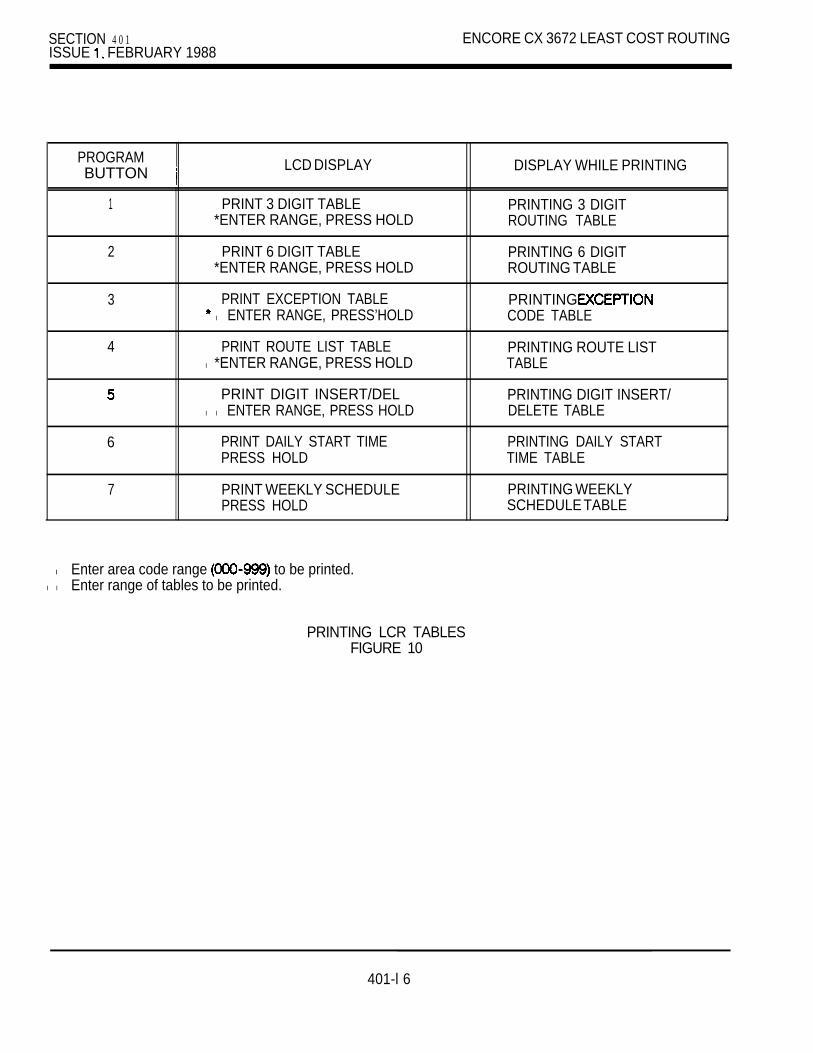
SECTION 4 0 1ISSUE FEBRUARY 1988
ENCORE CX 3672 LEAST COST ROUTING
PROGRAMBUTTON LCD DISPLAY DISPLAY WHILE PRINTING
1 PRINT 3 DIGIT TABLE PRINTING 3 DIGIT*ENTER RANGE, PRESS HOLD ROUTING TABLE
2 PRINT 6 DIGIT TABLE PRINTING 6 DIGIT*ENTER RANGE, PRESS HOLD ROUTING TABLE
3 PRINT EXCEPTION TABLE PRINTING l ENTER RANGE, PRESS’HOLD CODE TABLE
4 PRINT ROUTE LIST TABLE PRINTING ROUTE LISTl *ENTER RANGE, PRESS HOLD TABLE
PRINT DIGIT INSERT/DEL PRINTING DIGIT INSERT/l l ENTER RANGE, PRESS HOLD DELETE TABLE
6 PRINT DAILY START TIME PRINTING DAILY STARTPRESS HOLD TIME TABLE
7 PRINT WEEKLY SCHEDULE PRINTING WEEKLYPRESS HOLD SCHEDULE TABLE
l Enter area code range to be printed.l l Enter range of tables to be printed.
PRINTING LCR TABLESFIGURE 10
401-l 6

ENCORE CX 3672 LEAST COST ROUTING SECTION 401 FEBRUARY 1988
The following is an example of a printout forLCR tables.
CODE LEADING 1 NON-LEADING 1
RR PP 6 RR PP 6- - - - - - - - - - -213 01 11 Y N253 08 08 N N303 05 11 N N411 N 03 N602 03 11 N ## N818 14 Y ## N911 N 00 03 N
DIGIT TABLE
AREA ROUTECODE NO OFFICE CODES
213 00 224 225 245 246249 333 456 561
818 13 255 318 458 459
CODE ROUTE NO
0 009 1520 13
START TIME TABLE WEEKLY SCHEDULE TABLE
TABLE TIME- - - - - - - - - - - - - - - - -08001700
3 2 3 0 02300
ROUTE LIST TABLE
ROUTE TIME CO GROUP- - - - - - - - - - - - - - - - - - - - - - - - - -00 5 02
3 192 166 03
2 1 064 12
3 5 024 6 07
2 18
01 1 5 016 03
2 063 184 12
3 5 023 192 16
4 6 07
INS/DEL TABLE
TABLE DIGITS
01 DEL 1602PRE 345
02 DEL 12144921687PRE 1214306POST 8545
T W F S S- - - - - - - - - - - - - - - - - - - - - - -0 8 0 0 1 1 1 1 1 3 31700 2 2 2 2 2 3 22300 3 3 3 3 3 3 32300 3 3 3 3 3 3 3
401-17
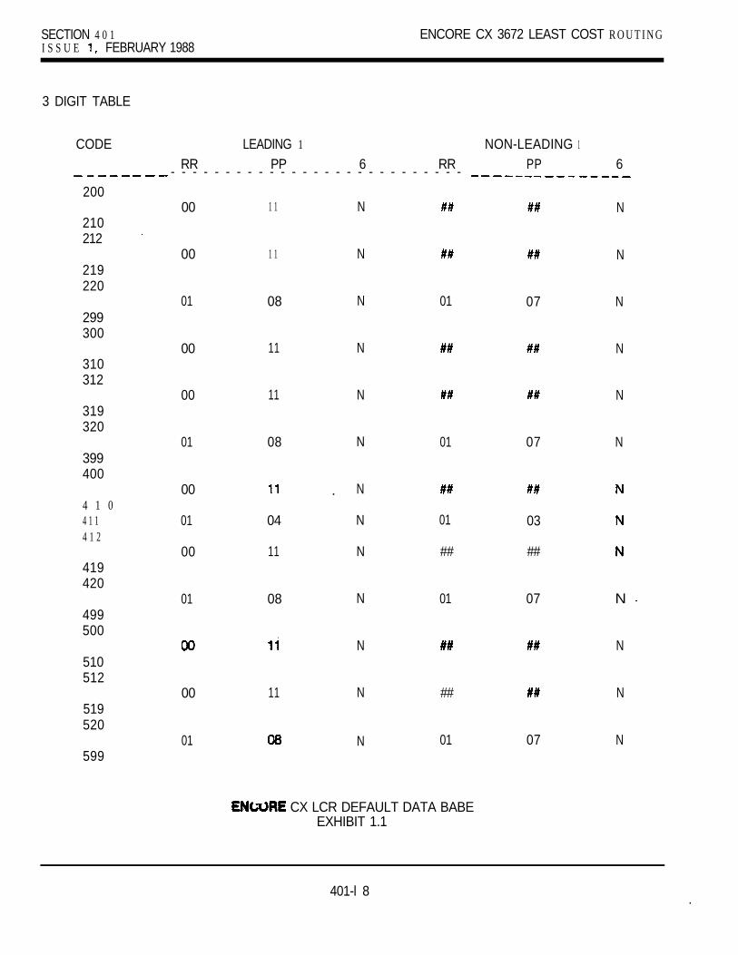
SECTION 4 0 1 ENCORE CX 3672 LEAST COST R O U T I N GI S S U E FEBRUARY 1988
3 DIGIT TABLE
CODE LEADING 1 NON-LEADING 1
RR PP 6 RR PP 6- - - - - - - - - - - - - - - - - - - - - - - - - - -200
00 1 1 N N210212
00 1 1 N N219220
01 08 N 01 07 N299300
00 11 N N310312
00 11 N N319320
01 08 N 01 07 N399400
00
01
00
N
N
N
.
04
11
01
##
03
##
4 1 04 1 14 1 2
419420
01 08 N 01 07 N 499500
N N510512
00 11 N ## N519520
01 N 01 07 N599
CX LCR DEFAULT DATA BABEEXHIBIT 1.1
401-l 8 .

ENCORECX3672 SECTION 401 FEBRUARY1988
CODE LEADING 1 NON-LEADING1RR PP 6 RR PP 6 - - - - - - - - _ _ _ _ _ _ _ _ _ _ _ _ _ _ _ _ _ _ _
600
610612
619620
699700
710712
719720
799800
810812
819820
899900
910911912
919920
00
00
01
00
00
01
00
00
01
01
01
01
11
11
11
11
08
11
11
08
11
04
11
08
N
N
N
N
N
N
N
N
N
N
N
N
N
01
##
01
##
##
##
01
01
LCR DEFAULT DATA BASE (CONT’D)EXHIBIT 1.2
07
##
07
##
03
07
N
N
N
N
N
N
N
N
N
N
N
N
401-19

SECTION 401 ENCORE CX 3672 LEAST COST ROUTINGISSUE FEBRUARY 1988
ROUTE TIME CO GROUP INS/DEL- - - - - - - - - - - - -00 1 2
2 2 3 2 ##4 2
01 1 12 13 1 ##4 1 ##
ROUTE LIST TABLEEXHIBIT 1.3
401-20

ENCORE CX 36112 SECTION 402FIELD CONVERSION KIT ISSUE JULY 1966
ENCORE CX 36112 DESIGN AND CONFIGURATION
TABLE OF CONTENTS
DESCRIPTION PAGE
1. INTERCOM PATHS. . . . . . . . . . . . . . . . . . . . . . . . . . . . . ..*..................... 1
LIST OF TABLES
1. SYSTEM COMPONENT LIST . . . . . . . . . . . . . . . . . . . . . . . . . . . . . . . . . . . . . . . . . . . . . 2. POWER SUPPLY REQUIREMENTS . . . . . . . . . . . . . . . . . . . . . . . . . . . . . . . . . . . . . . . 2
402-A
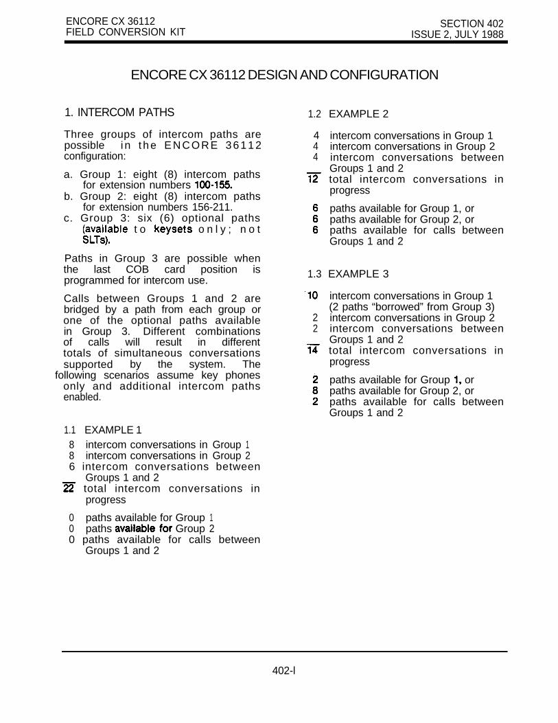
ENCORE CX 36112 SECTION 402FIELD CONVERSION KIT ISSUE 2, JULY 1988
ENCORE CX 36112 DESIGN AND CONFIGURATION
1. INTERCOM PATHS
Three groups of intercom paths arepossible i n t he ENCORE 36112configuration:
a. Group 1: eight (8) intercom pathsfor extension numbers
b. Group 2: eight (8) intercom pathsfor extension numbers 156-211.
c. Group 3: six (6) optional paths t o o n l y ; n o t
.
Paths in Group 3 are possible whenthe last COB card position isprogrammed for intercom use.
Calls between Groups 1 and 2 arebridged by a path from each group orone of the optional paths availablein Group 3. Different combinationsof calls will result in differenttotals of simultaneous conversationssupported by the system. The
following scenarios assume key phonesonly and additional intercom pathsenabled.
1.1 EXAMPLE 18 intercom conversations in Group 18 intercom conversations in Group 26 intercom conversations between
Groups 1 and 2 total intercom conversations in
progress
0 paths available for Group 10 paths Group 20 paths available for calls between
Groups 1 and 2
1.2 EXAMPLE 2
444
1.3 EXAMPLE 3
22
intercom conversations in Group 1intercom conversations in Group 2intercom conversations betweenGroups 1 and 2total intercom conversations inprogress
paths available for Group 1, orpaths available for Group 2, orpaths available for calls betweenGroups 1 and 2
intercom conversations in Group 1(2 paths “borrowed” from Group 3)intercom conversations in Group 2intercom conversations betweenGroups 1 and 2total intercom conversations inprogress
paths available for Group orpaths available for Group 2, orpaths available for calls betweenGroups 1 and 2
402-l

SECTION 402 ENCORE CX 36112 AN0 CONFIGURATIONISSUE 1. JULY 1988
TABLE 1 . SYSTEM COMPONENT LIST
PART NO. ABBREVIATION DESCRIPTION
2993503 Basic KSU (same as ENCORE 3672)
2993505 EXP-36112 36112 Field Conversion Kit:one (1) Expansion KSUone Power Cage
2994402 EPB Enhanced Processor Board’
2993612 EIB Expanded interface Board
12 Software for 36112 features I
2996303 Software for 36112 features LCR
2993701 COB Central Office Interface Board
2993702 KIB Key Telephone Interface Board
2994101 Power Supply
2994102 DC/DC Converter BCB
2994103 DC/DC Converter with BCB
l Replaces CPB (2994401)
TABLE 2. POWER SUPPLY REQUIREMENTS
C O N F I G U R A T I O N POWER SUPPLIES DC/DC CONVERTERS
Basic KSU 1 1
Add second APL, 2 1EIB, and/or
Add (slots
3 2
,
402-2

ENCORE CX 8 1 6 3672 SECTION 500KEY TELEPHONE SYSTEM ISSUE 2, SEPTEMBER 1988
GENERAL REGULATORY AGENCY INFORMATION
TABLE OF CONTENTS
DESCRIPTION PAGE
1. INFORMATION TO BE SUPPLIED TO USER1.1 USER’S RESPONSIBILITY TO TELEPHONE COMPANY.1.2 HEARING AID COMPATIBILITY1.3 RIGHTS OF TELEPHONE COMPANY . . . . . . . . . . . . . . . . . . . . . . . . . . . . . . . . . . . 11.4 IN CASE OF TROUBLE1.5 NOTICE OF COMPLIANCE. . . . . . . . . . . . . . . . . . . . . . . . . . . . . . . . . . . . . . . . . . .1.6 CANADIAN REGULATIONS. . . . . . . . . . . . . . . . . . . . . . . . . . . . . . . . . . . . . . . . . . .
500-A

SECTION KEY TELEPHONE SYSTEM ISSUE 2. SEPTEMBER 1988
GENERAL REGULATORY AGENCY INFORMATION
1. INFORMATION TO BE SUPPLIED TO USERThe information in the following paragraphs must beprovided by you (the Executone Distributor) to theENCORE CX Key Telephone System user inaccordance with FCC Regulations, Sections:68.218 (b) (d); 68.2; 68.108; 68.110 (b).
1.1 USER’S TOTELEPHONE COMPANY
It is the user’s responsibility to notify the telephonecompany of the connection or disconnection of theExecutone ENCORE CX Key Telephone System.In addition, the user must provide the followinginformation to the telephone company:
a.
l b.
C.
d.
e.f.
Make and Model: Executone ENCORE CXKey Telephone System.
FCC Registration Number:ENCORE CX 816: ENCORE CX 3672:
Ringer Equivalence Number: for 36720.48 for 816
Type of jack to be ordered from the telephone.company: RJ21 X for 3672 or 1 C for 816.
OPS Facility Interface Code (FIC):
OPS Signaling Type: Loop
NOTEYou, the Executone Distributor, must provide theabove information to the user. Alternately, the usermay allow you (the Executone Distributor) todeal with the telephone company on his behalf. It isthen your responsibility to provide aboverequired information to the telephone company.To deal with the telephone company on the user’sbehalf, you must have received from the user a“Letter of Representation”. See sample letter on
l If no single line telephones are installed in the
system or if no key telephones are programmed touse a group access code, KF-E (3672) maybe used.
1.2 AIDCOMPATIBILITY
a. The ENCORE CX Key Telephone System cannotbe used with party line service or coin
b. The ENCORE CX Key Telephone System ishearing aid compatible.
1.3 RIGHTS OF THE TELEPHONE COMPANYShould the ENCORE CX Key Telephone Systemcause harm to the telephone, network, the telephonecompany shall, where practical, notify the customerthat temporary discontinuance of may berequired. However, where prior notice is notpractical, the telephone company may temporarilydiscontinue service if such action is reasonable in thecircumstances. In case of such temporarydiscontinuance, the telephone company shall:
a.
b.
C.
Promptly notify the customer of such temporarydiscontinuance.
Give the customer the opportunity to correct thesituation which gave rise to the temporarydiscontinuance.
Inform the customer of the right to bring acomplaint to the Commission pursuant to theprocedures set forth in Subpart E of Part.68of the FCC rules.
The telephone company may make changes in itscommunications facilities, equipment, operations orprocedures, where such action is reasonablyrequired in the operation of its business and is notinconsistent with the rules and regulations of Part 68of the FCC rules. If such changes can bereasonably expected to render any customer’sterminal equipment incompatible with telephonecompany communications facilities, or requiremodification or alteration of such terminal equipment,or otherwise materially affect its use or performance,the customer shall be given adequate notice inwriting to allow the customer an opportunity tomaintain uninterrupted service.
1.4 IN CASE OF TROUBLEif any problem should develop with the ENCORE CXKey Telephone System, the user must not attempt tomake any repair. User contact his localExecutone Distributor for service.
500-l
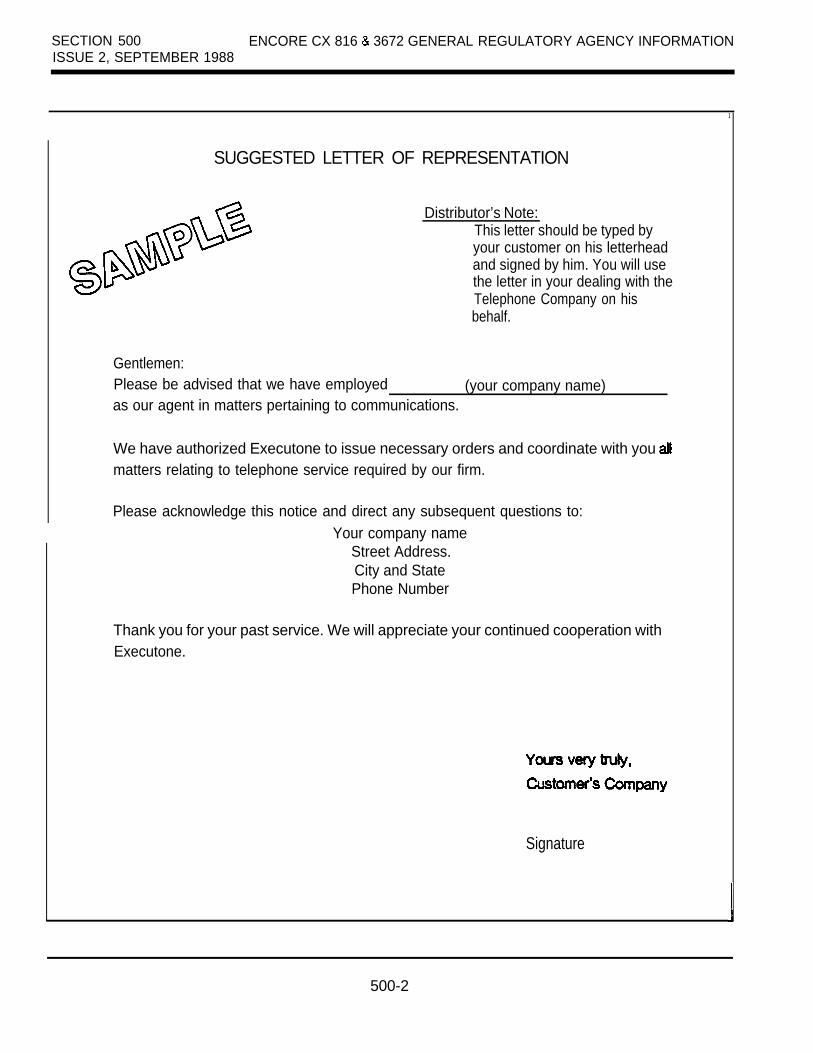
SECTION 500 ENCORE CX 816 3672 GENERAL REGULATORY AGENCY INFORMATIONISSUE 2, SEPTEMBER 1988
1
SUGGESTED LETTER OF REPRESENTATION
Distributor’s Note:This letter should be typed byyour customer on his letterheadand signed by him. You will usethe letter in your dealing with theTelephone Company on hisbehalf.
Gentlemen:Please be advised that we have employed (your company name)as our agent in matters pertaining to communications.
We have authorized Executone to issue necessary orders and coordinate with you matters relating to telephone service required by our firm.
Please acknowledge this notice and direct any subsequent questions to:Your company name
Street Address.City and StatePhone Number
Thank you for your past service. We will appreciate your continued cooperation withExecutone.
Signature
500-2
ENCORE CX 816 3672 GENERAL REGULATORY AGENCY INFORMATION SECTION 5002. SEPTEMBER 1988
1.5 NOTICE OF COMPLIANCEThe CX Key Telephone complies with rulesregarding radiation and radio frequency emission byClass A computing devices. In accordance with FCCStandard 15 (Subpart J) the following informationmust be supplied to the end user:
“WARNINGThis equipment generates and uses energy,and if not installed and used in accordance withthe Instruction Manual, it may cause interferenceto radio communications. It has been tested andfound to comply with the limits for a Class Acomputing device, pursuant to Subpart J ofPart 15 of the FCC Rules, which are designedto provide reasonable protection against suchinterference, when operated in a commercialenvironment. Operation of this equipment in aresidential area is likely to cause interference,in which case the user, at his own expense,will be required to take whatever measuresmay be required to correct the interference.”
1.6 CANADIAN REGULATIONSNOTICE
The Canadian Department of Communications labelidentifies certified equipment. This certificationmeans that the equipment meets certaintelecommunications network protective, operationaland safety requirements. The Department does notguarantee the equipment will operate to the user’ssatisfaction.
Before installing this equipment, users should ensurethat it is permissible to be connected to the facilitiesof the local telecommunications company.The equipment must also be installed using anacceptable method of connection. In some cases, the company’s inside wiring associated with singleline individual service may be extended by meansof a certified connector assembly (telephoneextension cord). The customer should be aware thatcompliance with the above condition may not preventdegradation of service in some situations.
Repairs to certified equipment should be made by anauthorized Canadian maintenance facility designatedby the supplier. Any repairs or alterations made bythe user to this equipment, or equipmentmalfunctions, may give the telecommunicationscompany cause to request the user to disconnectthe equipment.
Users should ensure, for their own protection, thatthe electrical ground connections of the powerutility, telephone lines and internal metallic waterpipe system, if present, are connected together.This precaution may be important in ruralareas.
CAUTION
Users should not attempt to make such connectionsthemselves, but should contact the appropriateelectric inspection authority, or electrician, asappropriate.
500-3
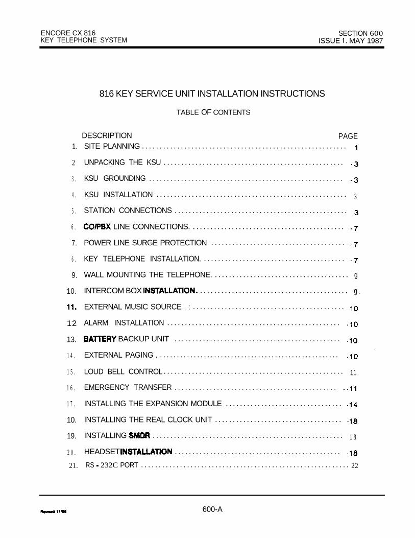
ENCORE CX 816 SECTION 600KEY TELEPHONE SYSTEM ISSUE MAY 1987
1.
2
3 .
4 .
5 .
6 .
7.
6 .
9.
10.
12
13.
1 4 .
1 5 .
1 6 .
1 7 .
10.
19.
2 0 .
21.
816 KEY SERVICE UNIT INSTALLATION INSTRUCTIONS
TABLE OF CONTENTS
DESCRIPTION PAGESITE PLANNING . . . . . . . . . . . . . . . . . . . . . . . . . . . . . . . . . . . . . . . . . . . . . . . . . . . . . . . . . .
UNPACKING THE KSU . . . . . . . . . . . . . . . . . . . . . . . . . . . . . . . . . . . . . . . . . . . . . . . . . . .
KSU GROUNDING . . . . . . . . . . . . . . . . . . . . . . . . . . . . . . . . . . . . . . . . . . . . . . . . . . . . . . .
KSU INSTALLATION . . . . . . . . . . . . . . . . . . . . . . . . . . . . . . . . . . . . . . . . . . . . . . . . . . . . . . 3
STATION CONNECTIONS . . . . . . . . . . . . . . . . . . . . . . . . . . . . . . . . . . . . . . . . . . . . . . . . .
LINE CONNECTIONS. . . . . . . . . . . . . . . . . . . . . . . . . . . . . . . . . . . . . . . . . . . .
POWER LINE SURGE PROTECTION . . . . . . . . . . . . . . . . . . . . . . . . . . . . . . . . . . . . . .
KEY TELEPHONE INSTALLATION. . . . . . . . . . . . . . . . . . . . . . . . . . . . . . . . . . . . . . . . .
WALL MOUNTING THE TELEPHONE. . . . . . . . . . . . . . . . . . . . . . . . . . . . . . . . . . . . . . . g
.INTERCOM BOX . . . . . . . . . . . . . . . . . . . . . . . . . . . . . . . . . . . . . . . . . . g
EXTERNAL MUSIC SOURCE . : . . . . . . . . . . . . . . . . . . . . . . . . . . . . . . . . . . . . . . . . . . .
ALARM INSTALLATION . . . . . . . . . . . . . . . . . . . . . . . . . . . . . . . . . . . . . . . . . . . . . . . . .
BACKUP UNIT . . . . . . . . . . . . . . . . . . . . . . . . . . . . . . . . . . . . . . . . . . . . . . .
EXTERNAL PAGING . . . . . . . . . . . . . . . . . . . . . . . . . . . . . . . . . . . . . . . . . . . . . . . . . . . . .
LOUD BELL CONTROL. . . . . . . . . . . . . . . . . . . . . . . . . . . . . . . . . . . . . . . . . . . . . . . . . . . 11
EMERGENCY TRANSFER . . . . . . . . . . . . . . . . . . . . . . . . . . . . . . . . . . . . . . . . . . . . . .
INSTALLING THE EXPANSION MODULE . . . . . . . . . . . . . . . . . . . . . . . . . . . . . . . . .
INSTALLING THE REAL CLOCK UNIT . . . . . . . . . . . . . . . . . . . . . . . . . . . . . . . . . . . .
INSTALLING . . . . . . . . . . . . . . . . . . . . . . . . . . . . . . . . . . . . . . . . . . . . . . . . . . . . . . 1 8
HEADSET . . . . . . . . . . . . . . . . . . . . . . . . . . . . . . . . . . . . . . . . . . . . . . .
RS 232C PORT . . . . . . . . . . . . . . . . . . . . . . . . . . . . . . . . . . . . . . . . . . . . . . . . . . . . . . . . . . . 22
600-A

SECTION 600ISSUE MAY 1987
ENCORE CX 816 INSTALLATION INSTRUCTIONS
3.4.5.6.
9.10.11.12.13.14.15.
BACKUP . . . . . . . . . . . . . . . . . . . . . . . . . . . . . . . . . . . . . . . . . . . . . . . . . . . . . . . 10 .2. J-l CONNECTING BLOCK LAYOUT. . . . . . . . . . . . . . . . . . . . . . . . . . . . . . . . . . . . . . . . . 153. J-2 CONNECTING BLOCK LAYOUT. . . . . . . . . . . . . . . . . . . . . . . . . . . . . . . . . . . . . . . . . 164. CO CONNECTING BLOCK LAYOUT . . . . . . . . . . . . . . . . . . . . . . . . . . . . . . . . . . . . . . . . 17
OF FIGURES
MOUNTING ARRANGEMENTS. . . . . . . . . . . . . . . . . . . . . . . . . . . . . . . . . . . . . . . . . . . . . .KSU MOUNTING DIMENSIONS . . . . . . . . . . . . . . . . . . . . . . . . . . . . . . . . . . . . . . . . . . . . .816 KEY SERVICE . . . . . . . . . . . . . . . . . . . . . . . . . . . . . . . . . . . . . . .816 KEY SERVICE UNIT- RIGHT SIDE . . . . . . . . . . . . . . . . . . . . . . . . . . . . . . . . . . . . . .816 WITH ALL EXTERNAL CONNECTIONS . . . . . . . . . . . . . . . . . . . . . . . . . . . . . . . . . .KEY TELEPHONE WIRING . . . . . . . . . . . . . . . . . . . . . . . . . . . . . . . . . . . . . . . . . . . . . . . . .WALL MOUNTING THE TELEPHONE . . . . . . . . . . . . . . . . . . . . . . . . . . . . . . . . . . . . . . . .
. . . . . . . . . . . . . . . . . . . . . . . . . . . . . . . . . . . . . . . . . . . . . . . . . . . . . . . . . . . g BACKUP UNIT. . . . . . . . . . . . . . . . . . . . . . . . . . . . . . . . . . . . . . . . . . . . . . . . . .
EXTERNAL CONNECTIONS . . . . . . . . . . . . . . . . . . . . . . . . . . . . . . . . . . . . . . . . . . . . . . .EMERGENCY TRANSFER . . . . . . . . . . . . . . . . . . . . . . . . . . . . . . . . . . . . . . . . . . . . . . . . .EXPANSION MODULE . . . . . . . . . . . . . . . . . . . . . . . . . . . . . . . . . . . . . . . . . . . . . . . . . . . .INSTALLING REAL CLOCK UNIT AND SIU. . . . . . . . . . . . . . . . . . . . . . . . . . . . . .TYPICAL STATION CABLE TERMINATION BLOCK).
g. . . . . . . . . . . . . . .
EXAMPLE DESIGNATION AND CUT-DOWN FOR BLOCK THE MDF . . . . . . . . . . . . . . . . . . . . . . . . . . . . . . . . . . . . . . . . . . . . . . . . . . . . . . . . . . . . 21
OF
600-B
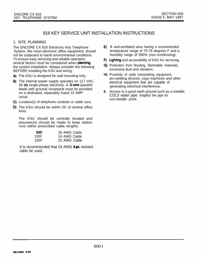
ENCORE CX 816 SECTION 600KEY TELEPHONE SYSTEM ISSUE MAY 1987
816 KEY SERVICE UNIT INSTALLATION INSTRUCTIONS
1. SITE PLANNINGThe ENCORE CX 816 Electronic Key TelephoneSystem, like most electronic office equipment, shouldnot be subjected to harsh environmental conditions.To ensure easy servicing and reliable operation,several factors must be considered when the system installation. Always consider the followingBEFORE installing the KSU and wiring:
The KSU is designed for wall mounting only.
The internal power supply operates on 117 VAC,60 single-phase electricity. A (parallelblade with ground) receptacle must be providedon a dedicated, separately fused 15 AMPcircuit.Location(s) of telephone conduits or cable runs.
The KSU should be within 25’ of central officelines.
The KSU should be centrally located andassurances should be made to keep stationruns within prescribed cable lengths.
26 AWG Cable1000’ 24 AWG Cable1500’ 22 AWG Cable
It Is recommended that 24 AWG twistedcable be used.
A well-ventilated area having a recommendedtemperature range of 70-78 degrees F and ahumidity range of 590% (non-condensing).
and accessibility of KSU for servicing.
Protection from flooding, flammable materials,excessive dust and vibration.
Proximity of radio transmitting equipment,arc-welding devices, copy machines and otherelectrical equipment that are capable ofgenerating electrical interference.Access to a good earth ground such as a metallicCOLD water pipe. inspect the pipe fornon-metallic joints.
600-l

SECTION 600 ENCORE CX 816 KSU INSTALLATION INSTRUCTIONS MAY 1987
OFF SPOOLS
J.2
FLAT PACK
FIGURE 1. MOUNTING ARRANGEMENTS
URE 2. KSU MOUNTING
REV
ENCORE CX 8 16 KSU INSTALLATION INSTRUCTIONS SECTION 600ISSUE MAY 1987
2. UNPACKING THE KSURemove the KSU from the shipping carton and placeit on a level working surface, face up. Inspect theKSU for physical damage. The KSU has limitedserviceable parts.
3. KSU To ensure that the system will operate property,a good earth ground is necessary. A metallicCOLD water pipe will usually provide a reliableground path. Carefully check that the pipe does notcontain insulated joints that could isolate the ground.In the absence of the cold water pipe, a ground rodor other source may be used. A No. 8 AWG copperwire should be used between the ground source andthe KSU. The ground wire should be kept as shortas possible and should be connected to the groundlug located on the bottom of the KSU. See Figure 3.
4. KSU INSTALLATIONThe KSU is designed for wall mounting only.The KSU should NOT be mounted directly on amasonry surface.If the KSU is to be mounted on a masonrysurface, a wooden backboard of sufficient sizeshould be attached to the wall and the KSUmounted on the backboard.
Mount the KSU on the backboard using 4fasteners. (The fasteners should be selectedcarefully so as to be capable of supporting theKSU.) Refer to Figure 2 for mounting holelocations and KSU dimensions.
The key system should be grounded using aninsulated 8 AWG copper wire. Attach one end tothe grounding lug on the KSU cabinet andfasten the other end to a good earth ground.See Figure 3.
The KSU power supply is located within theKSU. Because the KSU is a self-contained unit,all electrical connections are provided externally.The power cord exits the KSU at the bottom.Also at the bottom is a fuse holder that containsa 0.7 Amp. slow-blow fuse.Power for the system is distributed internally.The power cord exits the at the bottom and,for installer convenience, the cord 9 feet long.
The power cord should not be used with a plug adapter. A surge protector
should be used to protect the power supply fromelectrical surges. The surge protector shouid beinstalled in accordance with the manufacturer’sinstructions and applicable local electrical codes.See Figure 5.
5. STATION CONNECTIONSThere is one Amphenol-type female connectoron the left side of the KSU (J-l When theexpansion module is added, there will be a secondAmphenol-type connector on the left side of theKSU (J-2). Both J-l and J-2 connectors requireplug cables for proper attachment. The cablesshould be terminated on a connecting block for crossconnection to the distribution cabling to thetelephones.When connecting cable tails to the KSU, make surethe designation on the AMP hood matches thedesignation at the connector’s input on the KSU.
After plugging in the required cables, a “horse shoe” should be placed around the mated AMP
connectors to secure the cable to the KSUconnector.Verify that the wires are properly cross-connected.Observe the telephone standard wiring color codeswhenever possible. The J-l cable contains theconnections for the first 8 stations and themiscellaneous connections for paging, loud bellcontrol, music-on-hold, etc. The J-2 cable containsthe connections for the last 8 stations and has nomiscellaneous connections. See Figure 5.
CAUTION is NOT recommended that power be applied to
the system during the cable termination process.
600-3

SECTION 600 ENCORE CX 816 KSU INSTALLATION INSTRUCTIONSISSUE MAY 1987
CONNECTOR
. ADJ.
ADJ.PROGRAMMODULE
FUSE
FIGURE 3. KEY SERVICE UNIT-LEFT SIDE

ENCORE CX 616 KSU INSTALLATION INSTRUCTIONS SECTION 600ISSUE MAY 1987
FIGURE 4. KEY SERVICE SIDE
C CONNECTORSFOR CO LINES
-EMERGENCYTRANSFER
REQUIRES INTERFACE MODULE

STATION
ON HOLD
EXTERNAL PAGE
ALARM
LOUD CONTROL
MDF (J-2)
AC CONNECTIONWITH SURGE PROTECTOR
232C
I
I I I
11 C CONNECTORS CO LINES
EMERGENCY
FUSE
FIGURE 5. ENCORE CX 818 SYSTEM WITH ALL EXTERNAL
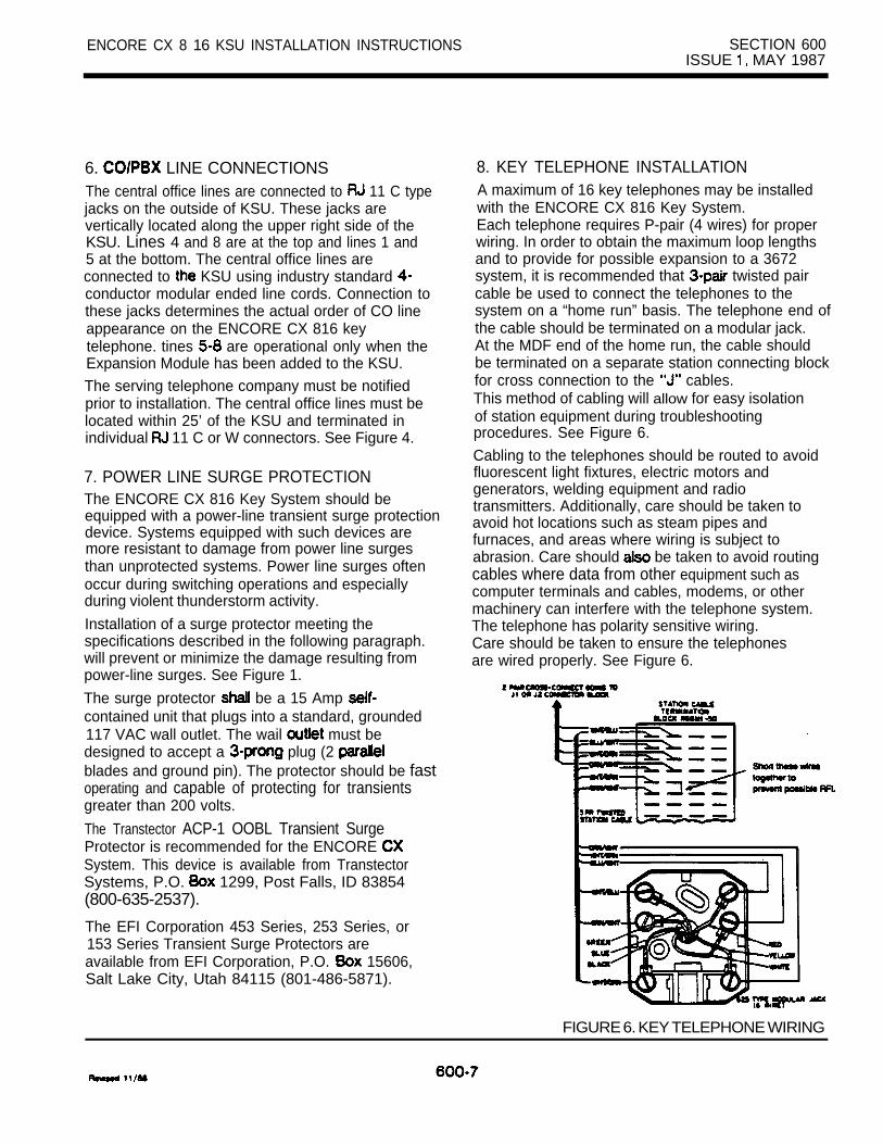
ENCORE CX 8 16 KSU INSTALLATION INSTRUCTIONS SECTION 600ISSUE MAY 1987
6. LINE CONNECTIONSThe central office lines are connected to 11 C typejacks on the outside of KSU. These jacks arevertically located along the upper right side of theKSU. Lines 4 and 8 are at the top and lines 1 and5 at the bottom. The central office lines areconnected to KSU using industry standard conductor modular ended line cords. Connection tothese jacks determines the actual order of CO lineappearance on the ENCORE CX 816 keytelephone. tines are operational only when theExpansion Module has been added to the KSU.The serving telephone company must be notifiedprior to installation. The central office lines must belocated within 25’ of the KSU and terminated inindividual 11 C or W connectors. See Figure 4.
7. POWER LINE SURGE PROTECTIONThe ENCORE CX 816 Key System should beequipped with a power-line transient surge protectiondevice. Systems equipped with such devices aremore resistant to damage from power line surgesthan unprotected systems. Power line surges oftenoccur during switching operations and especiallyduring violent thunderstorm activity.
Installation of a surge protector meeting thespecifications described in the following paragraph.will prevent or minimize the damage resulting frompower-line surges. See Figure 1.
The surge protector be a 15 Amp contained unit that plugs into a standard, grounded117 VAC wall outlet. The wail must bedesigned to accept a plug (2 blades and ground pin). The protector should be fastoperating and capable of protecting for transientsgreater than 200 volts.
The Transtector ACP-1 OOBL Transient SurgeProtector is recommended for the ENCORE System. This device is available from TranstectorSystems, P.O. 1299, Post Falls, ID 83854(800-635-2537).
The EFI Corporation 453 Series, 253 Series, or153 Series Transient Surge Protectors areavailable from EFI Corporation, P.O. 15606,Salt Lake City, Utah 84115 (801-486-5871).
8. KEY TELEPHONE INSTALLATIONA maximum of 16 key telephones may be installedwith the ENCORE CX 816 Key System.Each telephone requires P-pair (4 wires) for properwiring. In order to obtain the maximum loop lengthsand to provide for possible expansion to a 3672system, it is recommended that twisted paircable be used to connect the telephones to thesystem on a “home run” basis. The telephone end ofthe cable should be terminated on a modular jack.At the MDF end of the home run, the cable shouldbe terminated on a separate station connecting blockfor cross connection to the cables.This method of cabling will allow for easy isolationof station equipment during troubleshootingprocedures. See Figure 6.
Cabling to the telephones should be routed to avoidfluorescent light fixtures, electric motors andgenerators, welding equipment and radiotransmitters. Additionally, care should be taken toavoid hot locations such as steam pipes andfurnaces, and areas where wiring is subject toabrasion. Care should be taken to avoid routingcables where data from other equipment such ascomputer terminals and cables, modems, or othermachinery can interfere with the telephone system.The telephone has polarity sensitive wiring.Care should be taken to ensure the telephonesare wired properly. See Figure 6.
FIGURE 6. KEY TELEPHONE WIRING

SECTION 600ISSUE MAY 1987
ENCORE CX 8 16 KSU INSTALLATION
HANDSETRETAINER
JACK
REVERSIBLEBASE
THE BASEFOR
7. WALL THE TELEPHONE
600-8

ENCORE CX 816 KSU INSTRUCTIONS SECTION 600ISSUE MAY 1987
9. WALL MOUNTING THE TELEPHONEThe telephone can be converted to allow wallmounting by unsnapping the base plate and placingit into the wall mount position. Every telephone canbe converted for wall mounting without requiring anyextra parts. To convert the telephone for wall mounting:A) Place the telephone with the bottom facing up
toward you.
B) Press in on the upper left of the base plate.It unsnaps and out.
C) Remove the cord on the inside of thebase plate.
D) Insert connecting cord into the bottom of thetelephone. See Figure 7.
E) Reverse the base plate and snap it on theopposite side of the bottom of the telephone.The bottom of the telephone will now be leveland there will be 2 holes which will enable thetelephone to be placed on a regular telephonewall jack. Plug the connecting cord into the walljack.
F) up the number identification plate under thehandset and remove the screw.
G) Remove the handset retainer and turn it around.See Figure 7.
H) Replace the screw. The telephone is now readyfor wall mounting.
10. INTERCOM BOX INSTALLATIONThe ENCORE CX Intercom Box is designed toinitiate calls to preassigned stations as well asreceive intercom calls with handsfree operation. See Figure 8. The unit should be locatedin weather protected areas where paging ormonitoring is required. intercom box isconnected to a dedicated key telephone station linecard position.
The connection of Intercom to the KSU isidentical to that of the electronic Refer to paragraph 8 of this section.
The Intercom Box consists of a top housing andbottom mounting plate. The top housing has aspeaker, microphone, wire terminals and electroniccircuitry. The housings are separated by inserting athin, flat-edged tool at the bottom rim of theassembly. By pressing inward on the recessedretaining tab, the assembly will open.
The bottom plate of the Phone Box assembly isfastened to the wall by mounting with No. 8 or largerpan head screws. The cable is routed through thecable entry holes provided on the bottom plate andis connected to the screw terminal strip on the upperhousing. Four screw terminals are identified by wirecolor on the silk-screened printed circuit board tocorrespond with the wiring sequence at the down connector at the MDF.The slack wiring should be pulled back through thebottom mounting plate and the top housing snappedshut.
FIGURE 8. INTERCOM BOX
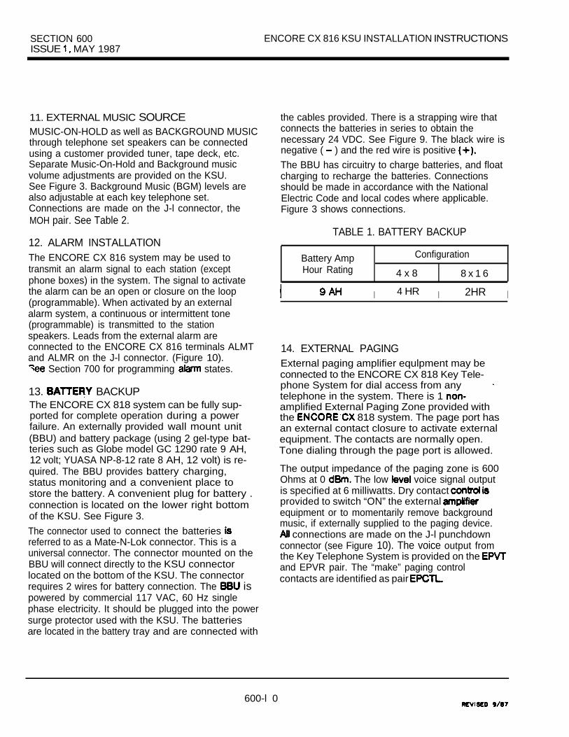
SECTION 600 ENCORE CX 816 KSU INSTALLATION INSTRUCTIONSISSUE MAY 1987
11. EXTERNAL MUSIC SOURCEMUSIC-ON-HOLD as well as BACKGROUND MUSICthrough telephone set speakers can be connectedusing a customer provided tuner, tape deck, etc.Separate Music-On-Hold and Background musicvolume adjustments are provided on the KSU.See Figure 3. Background Music (BGM) levels arealso adjustable at each key telephone set.Connections are made on the J-l connector, theMOH pair. See Table 2.
12. ALARM INSTALLATIONThe ENCORE CX 816 system may be used totransmit an alarm signal to each station (exceptphone boxes) in the system. The signal to activatethe alarm can be an open or closure on the loop(programmable). When activated by an externalalarm system, a continuous or intermittent tone(programmable) is transmitted to the stationspeakers. Leads from the external alarm areconnected to the ENCORE CX 816 terminals ALMTand ALMR on the J-l connector. (Figure 10).
Section 700 for programming states.
13. BACKUPThe ENCORE CX 818 system can be fully sup-ported for complete operation during a powerfailure. An externally provided wall mount unit(BBU) and battery package (using 2 gel-type bat-teries such as Globe model GC 1290 rate 9 AH,12 volt; YUASA NP-8-12 rate 8 AH, 12 volt) is re-quired. The BBU provides battery charging,status monitoring and a convenient place tostore the battery. A convenient plug for battery .connection is located on the lower right bottomof the KSU. See Figure 3.
The connector used to connect the batteries referred to as a Mate-N-Lok connector. This is auniversal connector. The connector mounted on theBBU will connect directly to the KSU connectorlocated on the bottom of the KSU. The connectorrequires 2 wires for battery connection. The ispowered by commercial 117 VAC, 60 Hz singlephase electricity. It should be plugged into the powersurge protector used with the KSU. The batteriesare located in the battery tray and are connected with
the cables provided. There is a strapping wire thatconnects the batteries in series to obtain thenecessary 24 VDC. See Figure 9. The black wire isnegative ( ) and the red wire is positive
The BBU has circuitry to charge batteries, and floatcharging to recharge the batteries. Connectionsshould be made in accordance with the NationalElectric Code and local codes where applicable.Figure 3 shows connections.
TABLE 1. BATTERY BACKUP
Battery Amp Configuration
Hour Rating 4 x 8 8 x 1 6
I 4 HR I 2HR I
14. EXTERNAL PAGINGExternal paging amplifier equlpment may beconnected to the ENCORE CX 818 Key Tele-phone System for dial access from anytelephone in the system. There is 1 amplified External Paging Zone provided withthe 818 system. The page port hasan external contact closure to activate externalequipment. The contacts are normally open.Tone dialing through the page port is allowed.
The output impedance of the paging zone is 600Ohms at 0 The low voice signal outputis specified at 6 milliwatts. Dry contact provided to switch “ON” the external equipment or to momentarily remove backgroundmusic, if externally supplied to the paging device.
connections are made on the J-l punchdownconnector (see Figure 10). The voice output fromthe Key Telephone System is provided on the and EPVR pair. The “make” paging controlcontacts are identified as pair
600-l 0
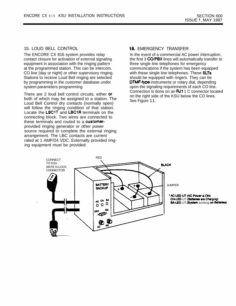
ENCORE CX 8 1 6 KSU INSTALLATION INSTRUCTIONS SECTION 600ISSUE MAY 1987
15. LOUD BELL CONTROLThe ENCORE CX 816 system provides relaycontact closure for activation of external signalingequipment in association with the ringing patternat the programmed station. This can be intercom,CO line (day or night) or other supervisory ringing.Stations to receive Loud Bell ringing are selectedby programming in the customer database undersystem parameters programming.
There are 2 loud bell control circuits, either both of which may be assigned to a station. TheLoud Bell Control dry contacts (normally open)will follow the ringing condition of that station.Locate the and terminals on theconnecting block. Two wires are connected tothese terminals and routed to a provided ringing generator or other powersource required to complete the external ringingarrangement. The LBC contacts are currentrated at 1 AMP/24 VDC. Externally provided ring-ing equipment must be provided.
CONNECTTO KSUMATE N-LOCKCONNECTOR
0
RED
EMERGENCY TRANSFERIn the event of a commercial AC power interruption,the first 3 lines will automatically transfer tothree single line telephones for emergencycommunications if the system has been equippedwith these single line telephones. These should be equipped with ringers. They can be
instruments or rotary dial, dependingupon the signaling requirements of each CO line.Connection is done on an 1 C connector locatedon the right side of the KSU below the CO lines.See Figure 11.
JUMPER
UT LIT working

J CONNECTOR
PIN
42
Y U G N
YUBN
MOH
MOH
EPVR- -
EPCTL- -
ALMT- -
MUSIC SOURCE
VOICE
MAKE CONTROL
EXTERNAL’

ENCORE CX 816 KSU INSTALLATION INSTRUCTIONS SECTION 600ISSUE 1. MAY 1987
PROCESSOR OR
I I I Ksu I FROM CI
STATION WIRING I
FROM EMERGENCYTRANSFER - N O T E 1 GREEN TIP
II I CO LINE 1
I l RED RINGI II
I I
RING III
I III
I I CO LINE 2I I YELLOW RING
I
I II I
RING I
II
I .I
I
I . II
I I
III
RING II
II I
,‘I
1: shown in power failure mode.
WHITE
II
CO 3l I
RING, BLUE
II
I
I
FIGURE 11. EMERGENCY TRANSFER
600-l 3

SECTION 600 MAY 1987
ENCORE CX 8 16 KSU INSTALLATION INSTRUCTIONS
17. INSTALLING THE EXPANSION MODULEThe system can be expanded to include an additional8 stations and 4 CO lines with the addition of anoptional expansion module. To install this module:
Disconnect the power by unplugging the KSU.Remove the Program Module.
Remove the 4 screws holding the cover andremove the KSU cover.
Remove the 2 screws holding the left side panelusing a 82 Phillips screwdriver.
Flip the left side panel so it lies fiat.Take the 2 ribbon cables included with theexpansion module and connect to the J-l andJ-2 connections on the main board.Carefully position the preformed bent ends intothe J-l and J-2 connections and press firmlyto insert. See Figure 12.
NOTE: The ribbon cable must be positioned sothat the conductor edge mates with theconductor edge of the J-l and J-2
Remove the snap-out plastic covers from thesides of the KSU for the additional connector and the additional 1 C connectors.
Connect the J-2 cable to the expansion module(on the bottom).
Take the expansion module and place it into theKSU, inserting the 1 C connectors into theright side of the KSU. Align the expansionmodule so that the 5 screw holes are over thestand-offs. Insert screws.
Connect the J-l cable to the expansion module.Raise the left side of the KSU and reinsertthe 2 screws.
Replace the KSU cover and reinsert the 4screws that hold it.
Replace the Program Module.
Reconnect the AC power.
I
connectors.
FIGURE 12. EXPANSION MODULE
600-l 4

ENCORE CX 816 KSU INSTALLATION INSTRUCTIONS SECTION 600ISSUE MAY 1987
TABLE 2. CONNECTING BLOCK LAYOUT
station 107
MOH 17
(VOICE) YUGN
ALMT YUBNALMR 19
EXTERNAL PAGE DRY CONTACTS
LOUD

SECTION 600 ENCORE CX 8 16 KSU INSTALLATION INSTRUCTIONSISSUE MAY 1987
TABLE 3. CONNECTING BLOCK LAYOUT
Station
Station 108
Station 109
Station 110
Station 111
Station 112
Station 113
Station 114
Station
Telephonetine CordGREENRED
YELLOWGREEN
REDBLACKYELLOWGREEN
REDYELLOWGREEN
REDYELLOWGREEN
RED
GREENREDBLACKYELLOWGREENREDBLACKYELLOW
GREENRED
2 pr. Twisted Function connectorStation Cable cable
26
DT 92
28
10DT 10DR 10 4
30
VR 11DT 11DR 11VT12 32
12DT12DR 12 8VT 13 34
13DT 13DR13 10
14 BWBL 36 14 BUBK
DT 14DR 14 12
38 15
DT 15 BWBN 15 14
40VR 16DT 16
1541
DR 16 16
600-l 6

ENCORE CX 816 KSU INSTALLATION INSTRUCTIONS SECTION 600ISSUE MAY 1987
TABLE 4. CO CONNECTING BLOCK LAYOUT
Location
BASICKSU
CO tine No.
1
2
3
Function
T2R2
T3R3
Connector
co 1
c o 2
c o 3
c o 4T4R4
5 T5c o 5
EXPANSION . . 6 T6 CO6R6
MODULE7 T7
R7 c o 7
8 T8R8 CO6
600-l 7

SECTION 600 ENCORE CX 816 KSU INSTALLATION INSTRUCTIONSISSUE MAY 1987
18. RCU INSTALLATIONTurn off the KSU power by removing the plugfrom the AC outlet.
Remove the program module.
Remove the 4 screws holding the KSU cover.Remove the cover.
Open the RCU box and verify the followingcomponents are included:
1 each RCU1 each battery1 each plastic beaded tie-wrap
Locate the battery. The end with the coloredring is negative. Install the battery into the batterysocket of the RCU, being careful to match thepolarity of the battery with the polarity of thesocket.
Push the beaded tie-wrap through the hole in theRCU next to the battery. Pull the tie-wrap aroundthe battery and through the cinch end to securethe battery.Refer to Figure 13. Locate the RCU socket(CN-2) and note the notched end of the socket.Align the notched end of the RCU with thenotched end of the RCU socket in the KSU.See Figure 13 (battery should face up).Take care not to install the RCU backwards,as damage to the unit could occur.insert the pins on the bottom of the RCU intothe RCU socket (CN-l), being careful to allof the pins with the socket. Apply pressure inthe middle of the RCU (not the ends) to avoidbreakage while seating the RCU into the socket.
RCU installation is now complete.Replace the KSU cover and Program Module.Reconnect AC power.
19. SMDR INSTALLATIONTurn off KSU power by removing plug from ACoutlet.
Remove Program Module from KSU.
Remove the 4 screws holding the KSU cover.Remove the cover.
Remove the cover plate.
Open SMDR Module box and verify the followingare enclosed:
1 SIU printed circuit board1 adapter cable
Gently insert the ribbon cable into the SIUconnector board. Then insert the cable into themain connector on the KSU. See Figure 13.Note conductive edge of ribbon cable.Remove the 2 jack screws from the SIU board.
Align the connector mounting hole withthe KSU mounting hole and insert. Reinsert the2 jack screws previously removed to hold theSIU in place.
The SMDR module installation is now complete.Replace the KSU cover and Program Module.Reconnect AC power.
20. HEADSET INSTALLATIONThe ENCORE CX key telephones have beendesigned to operate with industry standard modularheadset adapters and operator headsets. To modifyan ENCORE CX key telephone to support anexternal headset, plug the headset adapter the handset jack on the key telephone base.
the telephone handset cord into the headsetadapter box where indited by the headsetmanufacturer’s instructions.According to the programming section (700)under station programming, speakerphoneoperation must be disabled to allow headsetoperation. When this is done, such features asOn-Hook Diiing and Handsfree speakerphoneoperation are rendered inoperable. However,incoming page/voice announcements, toneringing and background music will still be heardover the speaker. On-hook and off-hookoperation is controlled with the MONITOR button.
600-l

ENCORE CX 816 KSU INSTALLATION INSTRUCTIONS SECTION 600ISSUE MAY 1987
POc o
CONNECTOR
FIGURE 13. RCU AND SIU INSTALLATION
600-l 9

SECTION 600 ENCORE CX 816 KSU INSTALLATION INSTRUCTIONSISSUE 1, MAY 1987
O R
ENCORE CX
IS to stationto on ofJ-2 block. l d
FIGURE 14. TYPICAL STATION CABLE TERMINATION BLOCK)

ENCORE CX 816 INSTRUCTIONS SECTION ISSUE 1, MAY 1987
to
l n g l b l n e b d . l b
J.2 Block.
r - 2
- - l
FIGURE 15. EXAMPLE DESIGNATION AND FOR BLOCK ON THE
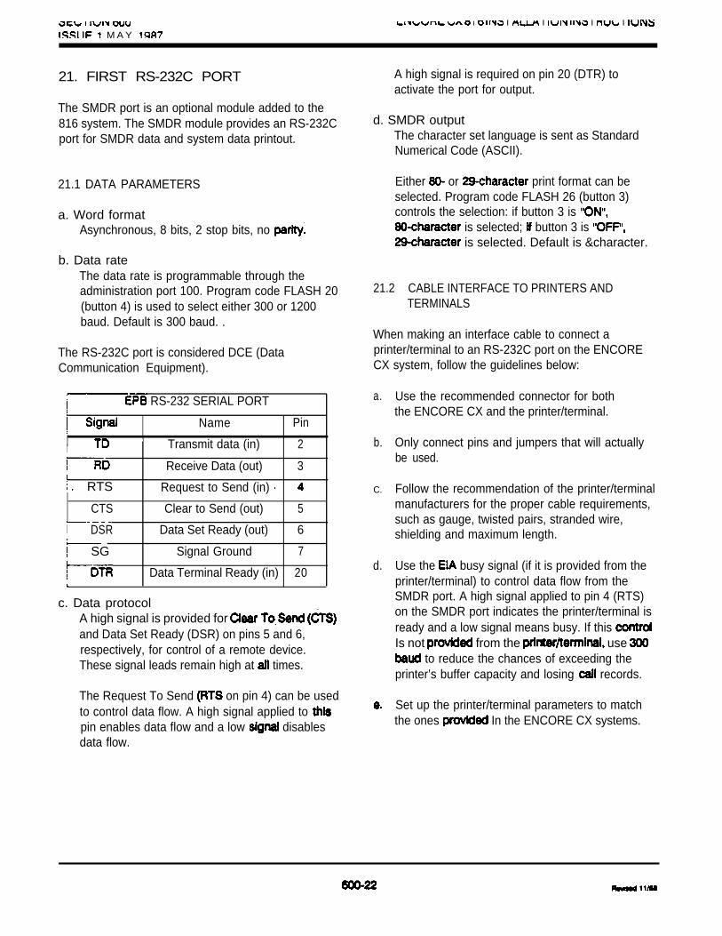
I I I I I
M A Y
21. FIRST RS-232C PORT
The SMDR port is an optional module added to the816 system. The SMDR module provides an RS-232Cport for SMDR data and system data printout.
21.1 DATA PARAMETERS
a. Word formatAsynchronous, 8 bits, 2 stop bits, no
b. Data rateThe data rate is programmable through theadministration port 100. Program code FLASH 20(button 4) is used to select either 300 or 1200baud. Default is 300 baud. .
The RS-232C port is considered DCE (DataCommunication Equipment).
RS-232 SERIAL PORT
Name Pin
I Transmit data (in) 2
Receive Data (out) 3
RTS Request to Send (in)
CTS Clear to Send (out) 5
I DSR Data Set Ready (out) 6
SG Signal Ground 7
Data Terminal Ready (in) 20
c. Data protocolA high signal is provided for and Data Set Ready (DSR) on pins 5 and 6,respectively, for control of a remote device.These signal leads remain high at times.
The Request To Send on pin 4) can be usedto control data flow. A high signal applied to pin enables data flow and a low disablesdata flow.
A high signal is required on pin 20 (DTR) toactivate the port for output.
d. SMDR outputThe character set language is sent as StandardNumerical Code (ASCII).
Either or print format can beselected. Program code FLASH 26 (button 3)controls the selection: if button 3 is
is selected; button 3 is is selected. Default is &character.
21.2 CABLE INTERFACE TO PRINTERS ANDTERMINALS
When making an interface cable to connect aprinter/terminal to an RS-232C port on the ENCORECX system, follow the guidelines below:
a.
b.
C.
d.
Use the recommended connector for boththe ENCORE CX and the printer/terminal.
Only connect pins and jumpers that will actuallybe used.
Follow the recommendation of the printer/terminalmanufacturers for the proper cable requirements,such as gauge, twisted pairs, stranded wire,shielding and maximum length.
Use the busy signal (if it is provided from theprinter/terminal) to control data flow from theSMDR port. A high signal applied to pin 4 (RTS)on the SMDR port indicates the printer/terminal isready and a low signal means busy. If this Is not from the use
to reduce the chances of exceeding theprinter’s buffer capacity and losing records.
Set up the printer/terminal parameters to matchthe ones In the ENCORE CX systems.

ENCORE 3672 SECTION 60 1KEY TELEPHONE SYSTEM ISSUE MAY 1987
1.
2
3.
4.
5.
6.
7.
6.
9.
10.
11.
12
13.
14.
15.
16.
17.
18.
19.
20.
21.
22.
3672 KEY SERVICE UNIT INSTALLATION INSTRUCTIONS
TABLE OF CONTENTS
DESCRIPTION PAGESITE PLANNING. . . . . . . . . . . . . . . . . . . . . . . . . . . . . . . . . . . . . . . . . . . . . . . . . . . . . . . . . . . ,
UNPACKING THE KSU . . . . . . . . . . . . . . . . . . . . . . . . . . . . . . . . . . . . . . . . . . . . . . . . . . . . .
KSU MOUNTING . . . . . . . . . . . . . . . . . . . . . . . . . . . . . . . . . . . . . . . . . . . . . . . . . . . . . . . . . . ,
KSU GROUNDING . . . . . . . . . . . . . . . . . . . . . . . . . . . . . . . . . . . . . . . . . . . . . . . . . . . . . . . . .
POWER LINE SURGE PROTECTION . . . . . . . . . . . . . . . . . . . . . . . . . . . . . . . . . . . . . . . .
. . . . . . . . . . . . . . . . . . . . . . . . . . . . . . . . . . . . . . . . .
KTU INSTALLATION . . . . . . . . . . . . . . . . . . . . . . . . . . . . . . . . . . . . . . . . . . . . . . . . . . . . . . . 7
STATION CONNECTIONS . . . . . . . . . . . . . . . . . . . . . . . . . . . . . . . . . . . . . . . . . . . . . . . . . .
CONNECTIONS . . . . . . . . . . . . . . . . . . . . . . . . . . . . . . . . . . . . . . . . . . . . . . . . . . . . .
EMERGENCY TRANSFER CONNECTIONS. . . . . . . . . . . . . . . . . . . . . . . . . . . . . . . . . . . ,
KEY TELEPHONE INSTALLATION: . . . . . . . . . . . . . . . . . . . . . . . . . . . . . . . . . . . . . . . . . .
DSS INSTALLATION . . . . . . . . . . . . . . . . . . . . . . . . . . . . . . . . . . . . . . . . . . . . . . . . . . . . . . .
SINGLE LINE TELEPHONE INSTALLATION . . . . . . . . . . . . . . . . . . . . . . . . . . . . . 15
INSTALLING RECEIVER/SENDER MODULE . . . . . . . . . . . . . . . . . . . . . . . . . . . . . . . . . .
WALL MOUNTING THE TELEPHONE. . . . . . . . . . . . . . . . . . . . . . . . . . . . . . . . . . . . . . .
HEADSET INSTALLATION. . . . . . . . . . . . . . . . . . . . . . . . . . . . . . . . . . . . . . . . . . . . . . . . . .
CONNECTION OF LOUD BELL CONTROL . . . . . . . . . . . . . . . . . . . . . . . . . . . . . . . . . . .
BACKGROUND MUSIC AND . . . . . . . . . . . . . . . . . . . . . . . . . . . . . . .
EXTERNAL PAGING CONNECTIONS. . . . . . . . . . . . . . . . . . . . . . . . . . . . . . . . . . . . . . . .
CONNECTIONS . . . . . . . . . . . . . . . . . . . . . . . . . . . . . . . . . . . . . . . . . . . . . . . . . .
INSTALLING THE EXPANSION . . . . . . . . . . . . . . . . . . . . . . . . . . . . . . . . . . . . . . . . .
INSTALLING THE RING GENERATOR UNIT . . . . . . . . . . . . . . . . . . . . . . . . . . . . . . . . . .
601 -A

SECTION 60 1ISSUE 1. MAY 1987
ENCORE 3672 INSTALLATION INSTRUCTIONS
23.
24.
25.
26.
1.2.3.
6.7.8.9.
10.11.12.13.14.15.16.17.18.19.20.
1.2.3.4.5.6.7.
TABLE OF CONTENTS (CONT’D)
DESCRIPTION PAGEFIRST PORT . . . . . . . . . . . . . . . . . . . . . . . . . . . . . . . . . . . . . . . . . . . . . . . . . . . . . .
PACKAGE V . . . . . . . . . . . . . . . . . . . . . . . . . . . . . . . . . . . . . . . . . . . . . . . . . . . . . . .
REMOTE PROGRAMMING AND MAINTENANCE . . . . . . . . . . . . . . . . . . . . . . . . . . . . . . . . ..3 3
OFF-SITE DATA TERMINAL PROGRAMMING . . . . . . . . . . . . . . . . . . . . . . . . . . . . . . . . . . .
LIST OF FIGURES
MOUNTING ARRANGEMENTS . . . . . . . . . . . . . . . . . . . . . . . . . . . . . . . . . . . . . . . . . . . . . . . .. . . . . . . . . . . . . . . . . . . . . . . . . . . . . . . . . . . . . . . . . . . . . . . . . . . . . . . . . .
BASIC KSU AND EXPANSION . . . . . . . . . . . . . . . . . . . . . . . . . . . . . . . . . . . . . . . . . . . .TYPICAL INTERCONNECTION LAYOUT. . . . . . . . . . . . . . . . . . . . . . . . . . . . . . .CONNECTING POWER SUPPLY TO DC/DC CONVERTER
6. . . . . . . . . . . . . . . . . . . . . . . .
CENTRAL OFFICE BOARD (COB). . . . . . . . . . . . . . . . . . . . . . . . . . . . . . . . . . . . . . . . . . . . .KEY TELEPHONE INTERFACE BOARD (KIB)
8. . . . . . . . . . . . . . . . . . . . . . . . . . . . . . . . . . .
BOARD (APL) . . . .ENHANCED PROCESSOR BOARD (EPB)
....................................................................................
EMERGENCY TRANSFER CIRCUIT . . . . . . . . . . . . . . . . . . . . . . . . . . . . . . . . . . . . . . . . .KEY TELEPHONE WIRING
: : . . . . . . . . . . . . . . . . . . . . . . . . . . . . . . . . . . . . . . . . . . . . . . . . . . .
DSS WIRING,
. . . . . . . . . . . . . . . . . . . . . . . . . . . . . . . . . . . . . . . . . . . . . . . . . . . . . . . . . . . . . .SINGLE LINE TELEPHONE WIRING. . . . . . . . . . . . . . . . . . . . . . . . . . . . . . . . . . . . . . . . . . . .WALL MOUNTING THE KEY TELEPHONE.
, . . . . . . . . . . . . . . . . . . . . . . . . . . . . . . . . . . . . .
INSTALLATION OF EXTERNAL PAGING ZONES. . . . . . . . . . . . . . . . . . . . . . . . . . . . . . . . . CONNECTIONS . . . . . . . . . . . . . . . . . . . . . . . . . . . .
THE RING GENERATOR UNIT. . . . . . . . . . . . . . . . . . . . . . .
. . . . . . . . . . . . . . . . . . . . . . . . . . . . . . . . . . . . . THE EXPANSION KSU
20 . . . . . . . . . . . . . . . . . . . . . . . . . . . . . . . . . . . . . . . . . ‘ . .
TYPICAL STATION CABLE TERMINATION BLOCK).21
. . . . . . . . . . . . . . . . .RECORDED ANNOUNCE DEVICE HOOKUP
. . . . . . . . . . . . . . . . . . . . . . . . . . . . . . . . . . . . . .
CONNECTING BLOCK . . . . . . . . . . . . . . . . . . . . . . . . . . . . . . . . . . . . . . . . . .STATION CONNECTING BLOCK . . . . . . . . . . . . . . . . . . . . . . . . . . . . . . . . . . . . . . .STATION CONNECTING BLOCK (SIB).
23. . . . . . . . . . . . . . . . . . . . . . . . . . . . . . . . . . . . . . . . . .
EMERGENCY TRANSFER UNIT CONNECTIONS.24
. . . . . . . . . . . . . . . . . . . . . . . . . . . . . . . . .P-l CONNECTING BLOCK. . . . . . . . . . . . . . . . . . . . . . . . . . . . . . . . . . . . . . . . . . . . . . . . . . . .P-2 CONNECTING BLOCK. . . . . . . . . . . . . . . . . . . . . . . . . . . . . . . . . . . . . . . . . . . . . . . . . . . .
BOARD CONNECTIONS.27
. . . . . . . . . . . . . . . . . . . . . . . . . . . . . . . . . . . . . . . .
601-B
ENCORE CX 3672KEY TELEPHONE SYSTEM
SECTION 60 1ISSUE MAY 1987
KEY SERVICE UNIT INSTALLATION INSTRUCTIONS
1. SITE PLANNINGThe ENCORE CX 3672 Key Telephone System,like most electronic office equipment, should not besubjected to harsh environmental conditions.To assure easy servicing and operation,several factors must be considered when planningthe system installation. Always remember thefollowing BEFORE installing the KSU and wiring:
The KSU is designed for wall mounting.
Both internal power supplies operate on 117 VAC,60 Hz phase electricity. A (parallelblade with ground) receptacle must be providedon a dedicated, separately fused 15 AMP circuit.
The KSU should be within 25’ of the telephonecompany RJ2 1 X. The KSU should becentrally located and care should be takento stay within prescribed cable lengths. It isrecommended that 24 AWG twisted cablebe used.Mounting space for standard backboard, or aplywood-type board for MDF blocks, if standard.backboard is not used.
A well-ventilated area having a temperature rangeof degrees F with a recommendedtemperature range of 70-78 degrees F and ahumidity range of (non-condensing).
Lighting and accessibility of KSU forservicing.
Protection from flooding, flammable materials,excessive dust and
Proximity of radii transmitting equipment,arcwelding devices, copy machines and otherelectrical equipment that are capable of generatingelectrical interference.
Access to a good earth ground such as a COLD water pipe. Inspect the pipe for non-metallicjoints.
2. UNPACKING THE KSURemove the Key Service Unit from the shippingcarton and stand it upright on a level workingsurface with the cover facing forward. Turn the4 screws on the front of the cabinet of a turn,tilt the cover and lift to remove. Remove allpacking materials from inside the KSU and inspectfor shipping damage. The KSU should be emptywhen received. Inside the KSU packing should bea mounting template. The mounting templateincludes mounting dimensions for the expansioncabinet. Some room should be left for futureexpansion in accordance with the template.
The items listed below are needed to have anoperating system. The number and type ofperipheral needed depends on the size ofthe system being installed.
Basic KSUPower SupplyDC/DC ConverterEnhanced Processor Board Peripheral
Central Office Board (COB)Key Telephone Interface Board (KIB)OHVA Key Telephone Interface Board (KIBOH)Single tine Interface Board (SIB)
optional Applications Card (APL)Emergency Transfer
3. MOUNTINGThe KSU is mounted in the following manner:
A) The KSU is designed for wall mounting KSU should not be mounted directly on a
masonry or dry walled surface. A woodenbackboard (plywood or pressed board) of
should be attached to the wallfor the KSU to be mounted upon. The KSUmounting template should be to identifyscrew hole locations. It is that the KSUand MDF connecting blocks be mounted on thebackboard. See Figure 1 for a typicalmounting arrangement.
Insert 4 0 or larger) screws into the backboardand tighten enough to hold the weight of the KSU.
the KSU and place it onto the screws.When the KSU is in position, the screws can betightened and the KSU is securely mounted.

SECTION 60 1ISSUE MAY 1987
ENCORE CX 3672 INSTALLATION INSTRUCTIONS
EXPANSION
RGU
GND
.
FIGURE 1. MOUNTING ARRANGEMENTS
4. KSU GROUNDINGTo ensure that the system will operate property, The wire should be kept as short as possible anda good earth ground is required. A metallic can be connected to the ground lug provided on theCOLD water pipe will usually provide a reliable ground lower right inside surface of the KSU. See Figure 3.path. Carefully check that the pipe does not containinsulated joints that could the ground. In theabsence of the COLD water pipe, a ground rod orother source may be used. A AWG copper wireshould be used between the ground source and theKSU (25 feet maximum). The farther from the groundsource, the larger the ground wire used should be.

ENCORE 3672 INSTALLATION INSTRUCTIONS SECTION 60 ISSUE 1. MAY
BASICKSU
EXPANSIONKSU
FIGURE 2. KSU

SECTION 60 1 ENCORE CX 3672 INSTALLATION INSTRUCTIONSISSUE MAY 1987
BASIC KSU
POWERSUPPLY 1
EXPANSION KSU
GROUND TERMINAL
FASTENERS STATION CABLES
GND TERMINAL
FASTENERS STATION CABLES
FIGURE 3. BASIC KSU AND EXPANSION KSU
COVER TO CONNECTIONS
TOEXP. KSU

ENCORE CX 3672 INSTALLATION INSTRUCTIONS SECTION 60 1ISSUE MAY 1967
5. POWER LINE SURGE PROTECTIONThe ENCORE CX 3672 Key System should beequipped with a power-line transient surge protectiondevice. Systems equipped with such devices aremore resistant to damage from power line surges thanunprotected systems. Power line surges often occurduring switching operations and especially duringviolent thunderstorm activity.
Installation of a surge protector meeting thespecifications described in the following paragraph willprevent or minimize the damage resulting frompower-line surges.
The surge protector shall be a ‘15 amp self-containedunit that plugs into a standard, grounded 1 17 VACwall outlet. The wall outlet must be designed to accepta plug (2 parallel blades and ground pin).The protector should be fast operating and capableof protecting for transients greater than 200 volts.
The Transtector ACP-1 OOBL Transient SurgeProtector is recommended for the ENCORE System. This device is available from TranstectorSystems, P.O. BOX 1299, Post Falls, ID 83854
The EFI Corporation 453 series, 253 series, or153 series Transient Surge Protectors areavailable from EFI Corporation, P.O. Box 15606, .Salt Lake City, Utah 84115
6. BACKUP INSTALLATIONBattery Charging is an option that can be purchasedalready installed on the DC/DC Converter. A separateexternal 24 volt DC battery package must beprovided.
AMPHOUR RATING
A. AND
CONNECTIONSA battery package should be selected that ensuresthe proper back-up time during power outages.A 24 VDC (normally two 12 VDC batteries) packagewith a 40 Amp hour rating is considered maximum.It is recommended that maintenance-free gel-typebatteries be used. The following must be consideredwhen connecting batteries:
1.
2.
3.
4.
5.
6.
7.
Batteries are to be placed in a limited accessroom or cabinet with adequate ventilation todissipate any battery gases that may be present.
The batteries are to be installed in accordancewith Article 480 of the National Electrical Code(NEC) and any other applicable codes.
A battery rack or case should be used to securethe batteries to prevent tipping or any movementthat could cause spilling of battery acid orshorting of terminals. The arrangement shouldprotect against ail hazards such as fire, spark,heat, gas fumes and accidents.
Use the shortest length of flexible cord type that will comply with the National
Electrical Code to connect batteries and powersupply. The cable should be located, routedand clamped (strain relief) in such a way as toprevent the batteries from moving should thecables be moved.A 15 Amp 48 V minimum fuse a 15 AmpDC instantaneous tripping circuit breaker shouldbe installed. Locate it at the batteries “in line”with the battery negative lead to protect thebattery from damage.
See 4 for wiring considerations. DC inputwire size should be sufficient to restrict voltagedrop to volt or less at rated input currentbetween the battery and power supply. The length is the sum of the lengths of the negativeand positive leads. Use wire sizes recommendedby the National Electrical Code and/or local
WARNING: Do not make connections with thepower applied to the power supply.(Remove “battery protection” fuse beforeconnecting batteries.)
601-5

SECTION 60 1 MAY 1987
ENCORE CX 3672 INSTALLATION INSTRUCTIONS
Connect the two-wire battery cable leads to theterminals marked + and Make surethe one wire is connected to the of thefirst battery, and the other wire is connected to the
terminal of the second battery (connected to afuse or circuit breaker). A single wire shouldconnect the terminal of the first battery with the
terminal of the second battery.
CAUTIONFuse must be removed or circuit breaker openprior to connecting the batteries to the KSU.
12 VOLT BATTERIES (2)
rIII
II
. II
I
The cable from the batteries is inserted into thelower left side of the front of the KSU (See Figure 3)and terminated on the screw terminals marked
and Double check connections and, when satisfied thatconnections are proper, replace the ‘BatteryProtection” fuse. Plug the AC into the power supplyand return “load” to the system. Close the circuitbreaker or fuse in line with batteries. Installation isnow complete and battery back-up can be tested.
-MARKER, ’ ,
MARKER
WIRECABLE
MARKER
L SINGLE WIRE RACK AND SEPARATOR
FIGURE 4. TYPICAL BATTERY INTERCONNECTION LAYOUT
TERMINAL
KSU
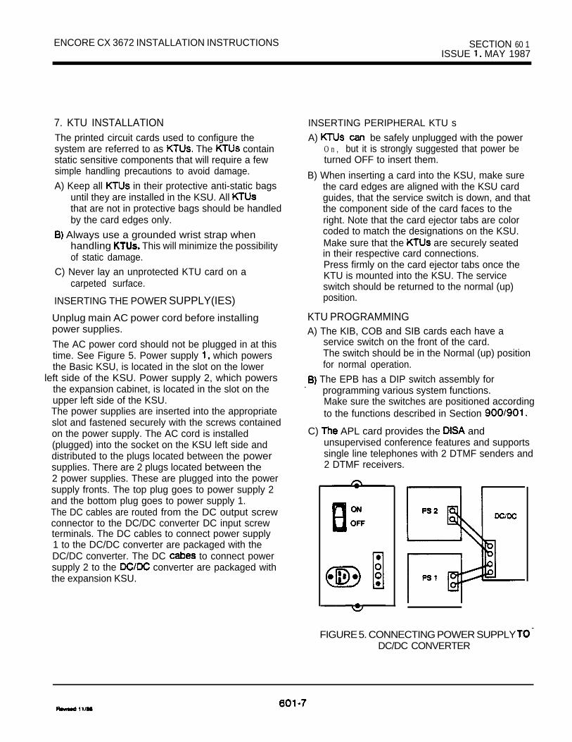
ENCORE CX 3672 INSTALLATION INSTRUCTIONS SECTION 60 1ISSUE MAY 1987
7. KTU INSTALLATIONThe printed circuit cards used to configure thesystem are referred to as The containstatic sensitive components that will require a fewsimple handling precautions to avoid damage.
A) Keep all in their protective anti-static bagsuntil they are installed in the KSU. All that are not in protective bags should be handledby the card edges only.
Always use a grounded wrist strap whenhandling This will minimize the possibilityof static damage.
C) Never lay an unprotected KTU card on acarpeted surface.
INSERTING THE POWER SUPPLY(IES)
Unplug main AC power cord before installingpower supplies.
The AC power cord should not be plugged in at thistime. See Figure 5. Power supply which powersthe Basic KSU, is located in the slot on the lower
left side of the KSU. Power supply 2, which powersthe expansion cabinet, is located in the slot on theupper left side of the KSU.The power supplies are inserted into the appropriateslot and fastened securely with the screws containedon the power supply. The AC cord is installed(plugged) into the socket on the KSU left side anddistributed to the plugs located between the powersupplies. There are 2 plugs located between the2 power supplies. These are plugged into the powersupply fronts. The top plug goes to power supply 2and the bottom plug goes to power supply 1.The DC cables are routed from the DC output screwconnector to the DC/DC converter DC input screwterminals. The DC cables to connect power supply1 to the DC/DC converter are packaged with theDC/DC converter. The DC to connect powersupply 2 to the converter are packaged withthe expansion KSU.
INSERTING PERIPHERAL KTU s
A) be safely unplugged with the powerO n , but it is strongly suggested that power beturned OFF to insert them.
B) When inserting a card into the KSU, make surethe card edges are aligned with the KSU cardguides, that the service switch is down, and thatthe component side of the card faces to theright. Note that the card ejector tabs are colorcoded to match the designations on the KSU.Make sure that the are securely seatedin their respective card connections.Press firmly on the card ejector tabs once theKTU is mounted into the KSU. The serviceswitch should be returned to the normal (up)position.
KTU PROGRAMMINGA) The KIB, COB and SIB cards each have a
service switch on the front of the card.The switch should be in the Normal (up) positionfor normal operation.
The EPB has a DIP switch assembly forprogramming various system functions.Make sure the switches are positioned accordingto the functions described in Section
C) APL card provides the andunsupervised conference features and supportssingle line telephones with 2 DTMF senders and2 DTMF receivers.
FIGURE 5. CONNECTING POWER SUPPLY DC/DC CONVERTER

SECTION 60 1 ENCORE CX 3672 INSTRUCTIONSISSUE 1. MAY 1967
NORMAL/SERVICE
COMPONENT SIDE
FIGURE 6. CENTRAL OFFICE BOARD (COB)

ENCORE CX 3672 INSTALLATION INSTRUCTIONS SECTION 60 ISSUE MAY 1987
(I’
i
L
601-Q

SECTION 60 1 1, MAY 1967
ENCORE CX 3672 INSTALLATION INSTRUCTIONS
:: S
: : 2
COMPONENT SIDE
I
RECEIVER- ;SENDER IMODULE I
EXTERNALPAGING
FIGURE 8. APPLICATION BOARD (APL)
601-10
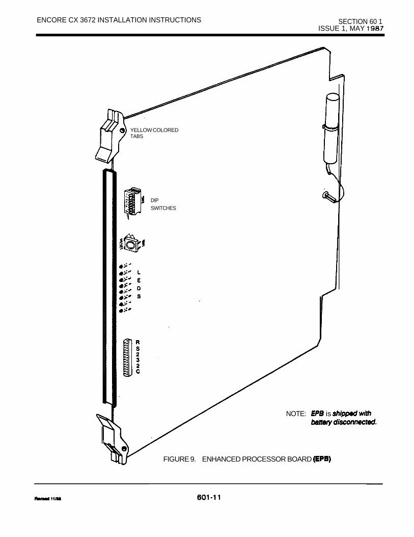
ENCORE CX 3672 INSTALLATION INSTRUCTIONS SECTION 60 1ISSUE 1, MAY
YELLOW COLOREDTABS
DIP
SWITCHES
NOTE: is
FIGURE 9. ENHANCED PROCESSOR BOARD

SECTION 60 1ISSUE MAY 1987
ENCORE CX 3672 INSTALLATION INSTRUCTIONS
8. STATION CONNECTIONSA type female connector isprovided on each of the station (KIB, SIB, etc.)cards. These allow the system to be cabled tothe main distribution frame (MDF). Twenty-five pairtelephone cabling must be prepared with matingconnectors to extend the KSU interface circuits tothe MDF. The cables should be routed through thecable clamps at the bottom of the KSU to the MDF.These cables are then terminated on industrystandard type punchdown connectorblocks. It is recommended that 66M l-50 split blockswith bridging clips be used to simplifytroubleshooting and to quickly isolate faults.
The type connectors will be on the frontedge of the printed circuit boards which are pluggedinto the green colored card slots. These connectorsrequire male plug-ended cables for properattachment. The actual quantity of cables requireddepends on the size of the system and the numberof cards installed in the system. Each time a station
is added to the system, another connector isequired. A maximum of 4 station cards can be
installed in the basic cabinet.
After the type cable connector has beenattached, the cable should be anchored to thecable clamps at the bottom of the KSU with tiewraps in order to prevent accidental disconnection.
The expansion KSU contains station slots which connectors 5-9. See Figure 1 and
Tables 2 and 3.
9. CONNECTIONSAn FCC approved RJ2 1 X connector should besupplied by the at the demarcation facility.The RJ2 1 X should be located within 25’ of theKSU. All line connections are made on the
and P2 cables. The connector is located onthe Basic KSU and the P2 connector on theExpansion KSU. A COB card must be installed inthe associated KSU card slots in order for the
line interface connections to be established.Refer to Tables and 6.
10. EMERGENCY TRANSFER CONNECTIONS4s an option, an Emergency Transfer Unit
be installed in the basic and expansion
In the event of a commercial AC power interruption,up to 6 lines per ETU can automaticallytransfer to single line telephones for emergencycommunications. These can be either rotary orDTMF but must be equipped with ringers. These SLT stations do not have to be usedfor intercom, but can be if so desired.The Emergency Transfer Unit (ETU) also providesthe contact closure for the Loud Bell Control.The ETU has a connectorthat allows a cable to be installed andterminated at the MDF. Refer to Table 4 for connections.
11. KEY TELEPHONE INSTALLATIONA maximum of 72 key telephones may be installedwith the ENCORE CX 3672 Key System (32 inthe Basic KSU and 40 in the Expansion KSU).The key telephones are interfaced with (or which have 8 circuits per board.Each circuit interface is extended from the KSUto the MDF through the front edge connector cableswhich are located on the KIB boards.
Also at the MDF are the terminated distributioncables that are run from each key telephone location.Each key telephone requires twisted cablewiring be used to connect the key telephones to thesystem on a “home run” basis. The telephone end ofthe cable is terminated on a modular jack and theMDF end of the cable should terminated on apunchdown block making up the MDF.
Cross connecting (jumper) wires connect thetelephone to the KIB allowing complete numberingflexibility. Each key telephone is assigned a intercom directory number in accordance with thelocations of the equipped
The Installer should when con-necting a key telephone while system power IsON. The first pair of wires is reserved for voicetransmission. The second pair supplies data,and the third pair for off-hook voice announce(KIBOH). The first pair is the return for 24 voltsand the second pair supplies the 24 volts. Bothpairs are overload protected by internal circuitryon the card. See figure 11. The proper polarityof the wired connections must be maintained forproper operation.

ENCORE CX 3672 INSTALLATION INSTRUCTIONS SECTION 60 1ISSUE MAY 1987
I
NOTE: shown in
FIGURE 10. EMERGENCY TRANSFER CIRCUIT

SECTION 60 1ISSUE MAY 1987
ENCORE CX 3672 INSTALLATION INSTRUCTIONS
2 J2
WING 4
CROSS-CWNLCT 4 MOCK OR
- -- -
- -q T- -
- -
- - - -,
- -
11
FIGURE 11. KEY TELEPHONE WIRING
FIGURE 12. DSS AND PHONE BOX WIRING
TO 4 OR
BLOCK
FIGURE 13. SINGLE LINETELEPHONE WIRING
ENCORE CX 3672 INSTALLATION INSTRUCTIONS SECTION 60 1ISSUE MAY 1987
12. DSS INSTALLATIONThe is assigned to operate with a keytelephone. Up to 3 units can be assigned to astation. There is no limit to the number of units thatcan be installed in a system, but each unit uses akey telephone interface circuit and this reducesstation capacity on a 1 per basis.
A twisted cable is required for connectingthe DSS unit. The cable should be placed from theDSS to the MDF in a “home run” manner. The DSSend of the cable is terminated on a modularjack and the MDF end is “punched down” on aterminal block for cross connection to theappropriate station cable. See Figure 12.Since the KSU supplies power to the DSS, no
or external power device is required.
13. SINGLE LINE TELEPHONE INSTALLATION
Single line telephones can be exchanged for keytelephones on an 8 for 8 basis. The following itemsare required for a system equipped with at least one Single tine Interface Board (SIB),one Ring Generator Unit (RGU), and one ApplicationBoard (APL).The SIB is color coded with green ejector tabs is plugged into any green designated card slot.Each SIB board supports 8 telephones (standardDTMF single line telephones and message waitingDTMF The Ring Generator Unit must beinstalled to provide power for tinging and messagewaiting for See Figure 13. When the numberof installed exceeds the handling of the2 DTMF receivers, the RSM module should beinstalled. The Receiver/Sender Module (RSM) plugsinto the Application Board and provides 4 additionalDTMF receivers and 1 additional sender to supportsingle line phones. Figure 8.
Each SLT requires one-pair cable. The cable shouldbe placed from the telephone location to the MDFin a “home run” manner. The telephone end of thecable run should be terminated in a modular jackand the MDF end should be “punched down” on aterminal block for cross connection to theappropriate station cable.
NOTE: Single Line Telephones operate on 24Vfor talk battery, which may not work withsome peripheral devices.
INSTALLING RECEIVER/SENDER MODULEA) Turn system power OFF and remove the
Application Board.B) Locate the and K2 connectors on the
Application Board. See Figure 8.
C) Note the and K2 connectors on the RSM.
D) Take the RSM and push the pin connectorgently onto the pins on the APL board.
E) Then push the K2 pin connector on the RSMgently onto the K2 pins on the APL board.
The Receiver/Sender Module is now installedand the APL can be returned to its place in theKSU. If more than 24 Single Line sets, use anextra RSM.
15. WALL MOUNTING THE TELEPHONEThe telephone can be converted to allow wallmounting by unsnapping the base plate and placingit into the wall mount position. Every telephone canbe converted for wall mounting without requiringany extra parts.
To convert the telephone for wall mounting:
1.
2.
3.
4.
5.
6.
7.
8.
Place the telephone with the bottom facing uptoward you.Press in on the upper edge of the left side at thebase plate. It unsnaps and lifts out.
Remove the connecting cord on the inside of thebase plate.Insert connecting cord into the bottom of thetelephone. See Figure 14.
Reverse the base plate and snap it on theopposite side of the bottom of the telephone.The bottom of the telephone will now be leveland there will be 2 holes which will enable thetelephone to be on a regular telephonewall jack. Plug the connecting cord into thewall jack.lift up the number identification plate and removethe screw.Remove the handset retainer and turn it around.See Figure 14.Replace the screw. The telephone is now readyfor wail mounting.
REVISED
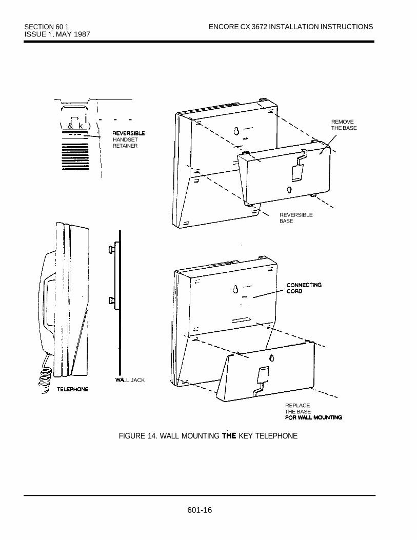
SECTION 60 1ISSUE MAY 1987
ENCORE CX 3672 INSTALLATION INSTRUCTIONS
i - - -\ & k ) \
.iHANDSETRETAINER
LL JACK
REMOVETHE BASE
REVERSIBLEBASE
REPLACETHE BASE
FIGURE 14. WALL MOUNTING KEY TELEPHONE
601-16
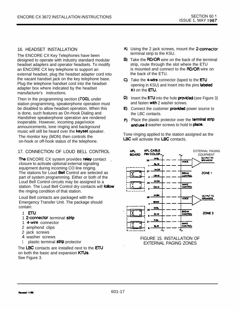
ENCORE CX 3672 INSTALLATION INSTRUCTIONS SECTION 60 ISSUE 1, MAY
16. HEADSET INSTALLATIONThe ENCORE CX Key Telephones have beendesigned to operate with industry standard modularheadset adapters and operator headsets. To modifyan ENCORE CX key telephone to support anexternal headset, plug the headset adapter cord intothe vacant handset jack on the key telephone base.Plug the telephone handset cord into the headsetadapter box where indicated by the headsetmanufacturer’s instructions.
Then in the programming section understation programming, speakerphone operation mustbe disabled to allow headset operation. When thisis done, such features as On-Hook Dialing andHandsfree speakerphone operation are renderedinoperable. However, incoming page/voiceannouncements, tone ringing and backgroundmusic will still be heard over the speaker.The monitor key (MON) then controls theon-hook or off-hook status of the telephone.
17. CONNECTION OF LOUD BELL CONTROL
ENCORE CX system provides contactclosure to activate optional external signalingequipment during incoming CO line ringing.The stations for Loud Control are selected aspart of system programming. Either or both of theLoud Bell Control circuits may be assigned to astation. The Loud Bell Control dry contacts will the ringing condition of that station.
Loud Bell contacts are packaged with theEmergency Transfer Unit. The package shouldcontain:
1 1 terminal 1 connector2 amphend clips2 jack screws4 washer screws1 plastic terminal protector
The contacts are installed next to the on both the basic and expansion See Figure 3.
Using the 2 jack screws, mount the terminal strip to the KSU.
Take the wire on the back of the terminalstrip, route through the slot where the ETUis mounted and connect to the wire onthe back of the ETU.
Take the connector (taped to the opening in KSU) and Insert into the pins
on the
Insert the into the hole (see Figure 3)and fasten 2 washer screws.Connect the customer power source tothe LBC contacts.Place the plastic protector over the
washer screws to hold ln
Tone ringing applied to the station assigned as the will activate the contacts.
EXTERNAL PAGINGEQUIPMENT
FIGURE 15. INSTALLATION OFEXTERNAL PAGING ZONES. .
601-17

SECTION 60 1ISSUE MAY 1987
ENCORE CX 3672 INSTALLATION INSTRUCTIONS
18. BACKGROUND MUSIC ANDMUSIC-ON-HOLD
Music-On-Hold as well as Background Musicthrough telephone set speakers can be connectedvia a customer-provided tuner, tape deck, etc.Separate and Background musicvolume adjustments are provided on the DC/DCconverter. Connections for both Background Musicand Music-On-Hold are made with an RCA jackconnector on the Converter. The inputimpedance of the music source is at 2K ohmsmaximum. Channel 1 is the Music-On-Hold andbackground music channel.Channel 2 is the second background music channel
(programmable).
19. EXTERNAL PAGING CONNECTIONSExternal paging amplifier equipment may beconnected to the ENCORE CX 3672 Key TelephoneSystem for dial access from any telephone in thesystem (except those denied paging access).
optional non-amplified External Paging zonesy be provided with the APL card. The output
Impedance of the paging zones is 600 ohms at0 The low level voice signal output is
.
specified at 5 milliwatts maximum. Dry contactcontrol is provided to switch ON the externalamplifier equipment or to momentarily removebackground music if supplied to the paging device.Connection is made on the APL board (see Figure15 and Table 7). The voice output is provided on the
-T/R pair for External Zone 1 and the pair for External Zone 2. The “break” contacts arepair (2) and the “make” contacts are pair
(2).
20. CONNECTIONS
One type connector is provided and islocated on the EPB board. There is an optionalsecond RS-232C connector which can be installed onthe APL board. The connector on the EPBcan be used for (station message recording) or for remote access features. If the secondRS-232C connector is installed on the APL board, thisconnector should be used for SMDR while thestandard connector on the EPB is used systemprogram printouts and remote access features(including Remote Programming and RemoteMaintenance). The is shown in Figure16.
SERIAL PORT
signal Name Pin
Transmit data (in) 2
Receive Data (out) 3
RTS Request to Send (in) 4
CTS to Send (out) 5
Data Set Ready (out) 6
SG Signal Ground 7
FIGURE 16. CONNECTIONS

3672 INSTALLATION INSTRUCTIONS SECTION 60 ISSUE MAY 1967
MESSAGE DETAIL RECORDINGThe SMDR feature provides detailed records of alloutgoing and/or incoming, long distance only or allcalls exceeding 30 seconds. This feature is enabledor disabled in system programming. By default,SMDR is not enabled and is set to record longdistance calls only (see Section. 700). If the SMDRfeature is enabled, the system starts collectinginformation about the call as soon as it starts andterminates when the call ends. If the call was longerthan 30 seconds, the following information is printed:1. 3 digits station originating the call2. 2 digits outside line used3. 5 digits length of the call4. digits- time of day5. 6 digits- month, day and year6. 24 digits-telephone number dialed7. 12 digits account code
Standard Format The standard format is 80characters and a single line printout with auto-matic carriage return and line feed instructionsto advance page. 8 data bits, 2 stop bits, noparity.
AAA HH:MM HH:MM: GG (CR) (LF)
station originator outside line number
HH:MM of HH:MM of dayCCC. ..CCC telephone number dialed
of call code return
feed
Format This format is a 3-Wprintout with automatic carriage return and line feedinstructions at the end of each line.AAA (CR) (LF)ccc...ccc (CR) (LF)
THE RS-232CCONNECTOR
A) Turn system power OFF and remove theApplication Board.
Locate the and S2 connectors on theAPL board. See Figure 8.
Note the and S2 pins on the SIU unit.Gently push the pins on the SIU onto the pin connectors on the APL board.
Then gently push the S2 pins on to the pin connectors on the APL board.Take the cable found in the SIU box and connectone end of the ribbon cable to the pins labeledS3 on the SIU (component side).
Route the cable between the Receiver/SenderModule and the connector.
Take the other end of the cable with the connector and mount it above the and champ connectors using the 2
screws provided.Refer to the table for data andfurther RS-232C Information
INSTALLING THE EXPANSION KSUThe expansion KSU can be installed at the sametime as the basic KSU or at a later time. In eithercase the system power must be turned off prior tothe installation. .
Refer to Item 3 of this section of the KSU mounting. The expansion KSU mounts tothe right of the basic KSU. the templateprovided, identify the screw hole locations.Insert me 2 screws into me wooden backboardand tighten enough to the weight of the unit.Remove the connector cover on the right side of
basic KSU. See Figure 18. Remove the last3 cards in the KSU.
Feed the 3 ribbon cables through the slotcreated by removing the side cover and plugthem into the basic KSU. See 18.
Take the power cable located in the expansionKSU and feed it through the slot in the basicKSU and plug it in. Then take the ribbon cable
connected to the basic KSU andconnect it to me expansion KSU.

SECTION 60 1 ENCORE CX 3672 INSTALLATION INSTRUCTIONSISSUE MAY 1987
E) Secure the 2 cabinets together by hooking themounting brackets on the left side of theexpansion KSU over the ones on the right sideof the basic KSU and at the same time positionthe expansion KSU on the 2 screws insertedin step A. Tighten the screws on the rightside of the expansion KSU.
F) Connect the ground of the basic KSU to theground of the expansion KSU with or largergauge wire.
22. INSTALLING THE RING GENERATOR UNITWhen the ENCORE CX 3672 is equipped withsingle line telephones, a Ring Generator Unit isneeded to provide ringing and power for messagewaiting The RGU should be mountednext to the Basic KSU. It should then be connectedto the KSU as shown in Figure 17.
YELLOWBLUE
FIGURE 17. INSTALLING THE RING GENERATOR
601-20
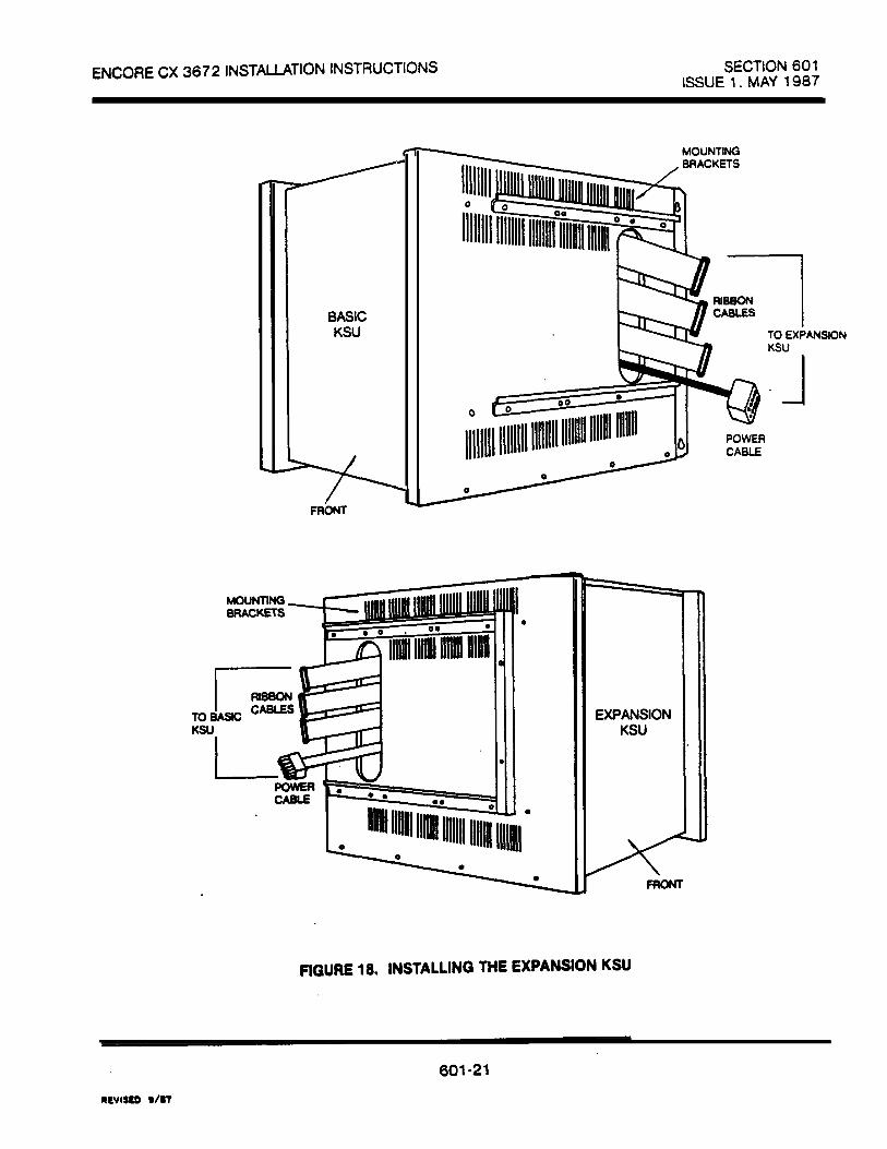
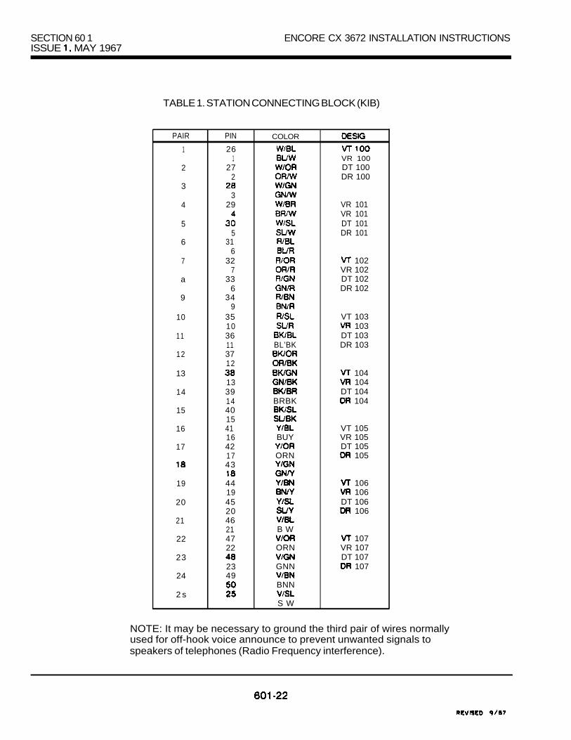
SECTION 60 1ISSUE MAY 1967
ENCORE CX 3672 INSTALLATION INSTRUCTIONS
TABLE 1. STATION CONNECTING BLOCK (KIB)
PAIR
1
2
3
4
5
6
7
a
9
10
1 1
12
13
14
15
16
17
19
20
21
22
23
24
2 s
PIN COLOR
261 VR 100
27 DT 1002 DR 100
329 VR 101
VR 101DT 101
5 DR 10131
632 102
7 VR 10233 DT 102
6 DR 10234
935 VT 10310 10336 DT 10311 BL’BK DR 1033712
10413 10439 DT 10414 BRBK 104401541 VT 10516 BUY VR 10542 DT 10517 ORN 10543
44 10619 10645 DT 10620 1064621 B W47 10722 ORN VR 107
DT 10723 GNN 1074924 BNN
S W
NOTE: It may be necessary to ground the third pair of wires normallyused for off-hook voice announce to prevent unwanted signals tospeakers of telephones (Radio Frequency interference).

ENCORE CX 3672 INSTALLATION INSTRUCTIONS SECTION 60 1ISSUE MAY 1987
TABLE 2. STATION CONNECTING BLOCK (KIBOH)
PAIR
2
3
4
5
6
7
6
9
10
11
12
13
14
15
16
17
18
19
2 0
21
22
23
24
25
PIN COLOR
26
2 :
329
3 :
733
634
1137
13391440154116421743184419452046214722
49245025
R/OR
SL’BK
BUY
ORN
BNN
VT 100VR 100
100100100
OVR 100101
VR 101DT 101
101101
OVR 101VT102VR 102DT 1 02
1 0202
OVR 10203
VR 1 03DT 1 03
GNN
BNN
SIN
103o v r 103OVR 103
VR 104DT 104
104104
OVR 104v r 105VR 105DT 105
105105
OVR 105VT 106VR 106DT 108
106106
OVR 106107
VR 107DT 107
107107107

SECTION 60 ISSUE MAY 1987
ENCORE CX 3672 INSTALLATION INSTRUCTIONS
TABLE 3. STATION CONNECTING BLOCK (SIB)
PAIR PIN
1 26
2 2 :2
3 283
4 29
55
6 31
77
8 33
9 34
1010
11 36
1212
1313
14 3914
15 401541
17 4217
18 4318
19 ‘4419
20 4520
21 4621
22 4722
23 4823
24 4924
25
COLOR
W-108
w. OR
OR/R
BWBLBUBKBWOR
BWSLSUBK
ORN
GNN
BNN
B W
VR115
GNN
BNN
S W
601-24

ENCORE CX 3672 INSTALLATION INSTRUCTIONS SECTION 60 1 MAY
TABLE 4. EMERGENCY TRANSFER UNIT CONNECTIONS
PAIR PIN COLOR
1 26
2 2 : SPARE2 SPARE
3 28 1 STOT3
4 29 1
2COIT5
6 31 SPARE6 SPARE
7 32
88
9 349
10 35 SPARE10 SPARE
1 1 36 3STOT
12BUBK
3STIT
13 4COIT13 4COIR
14 39 SPARE14 SPARE
15 40 4STOT15 4STOR41 4STIT16
17 4217
18 43 SPARE18 SPARE
19 4419
20 4520
21 VIBL
22 47 SPARE22 SPARE
2323
24 49
2525
to Mock
to SLT
to SIB
601-25
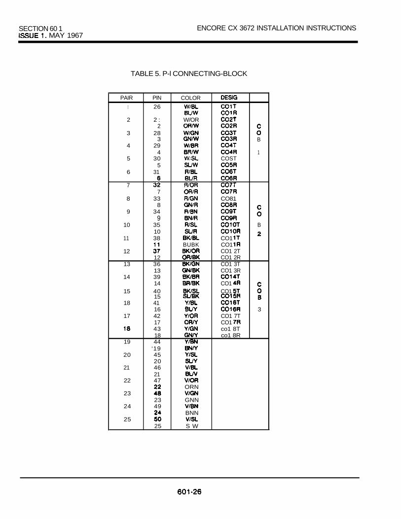
SECTION 60 1 ENCORE CX 3672 INSTALLATION INSTRUCTIONS MAY 1967
TABLE 5. P-l CONNECTING-BLOCK
PAIR
1
2
3
4
5
6
7
8
9
10
11
12
13
14
15
18
17
19
20
21
22
23
24
25
PIN
26
2 :2
283
294
305
31
733
834
9351038
1236133914401541164217431844
‘194520462147
2349
25
COLOR
W/OR
B
1COST
CO81
B
CO1 BUBK CO1
CO1 2TCO1 2RCO1 3TCO1 3R
CO1 CO1
3CO1 7TCO1 co1 8Tco1 8R
ORN
GNN
BNN
S W

ENCORE CX 3672 INSTALLATION INSTRUCTIONS SECTION 60 1ISSUE MAY 1987
TABLE 6. P-2 CONNECTING BLOCK
PAIR
1
2
3
4
5
6
7
6
9
10
1 1
12
13
14
15
16
17
18
19
20
21
22
23
24
25
PIN
127
228
329
531
632
733
834
93510381 137
13391440154116421743184419452046214722482349
25
COLOR
BL’W
s u w
OR/R
BUBK
.
SUBK
GNN
ORN
GNN
BNN
S W
CO1 CO1
C0B
4
B
5
B
6

SECTION 60 1 ENCORE CX 3672 INSTALLATION INSTRUCTIONSISSUE 1. MAY 1987
TABLE 7. APPLICATION BOARD CONNECTIONS
PAIR
1
2
3
4
5
8
7
8
9
1 0
1 1
12
13
14
15
18
17
18
19
20
21
22
23
24
25
PIN
261
272
283
2 9
531
632
733
834
9351038
123813391440154116421743184419452046214722482349245025
COLOR
PAGE VOICE 1
W/OR BREAK CONTACT
MAKE CONTACT
PAGE VOICE 2
BREAK CONTACT
MAKE CONTACT
BUBK
BUY
ORN
GNN
BNN

I I I I 601ISSUE 1, MAY 1987
ENCORE win IO
Me IO
lo
.
FIGURE TYPICAL STATION CABLE BLOCK)
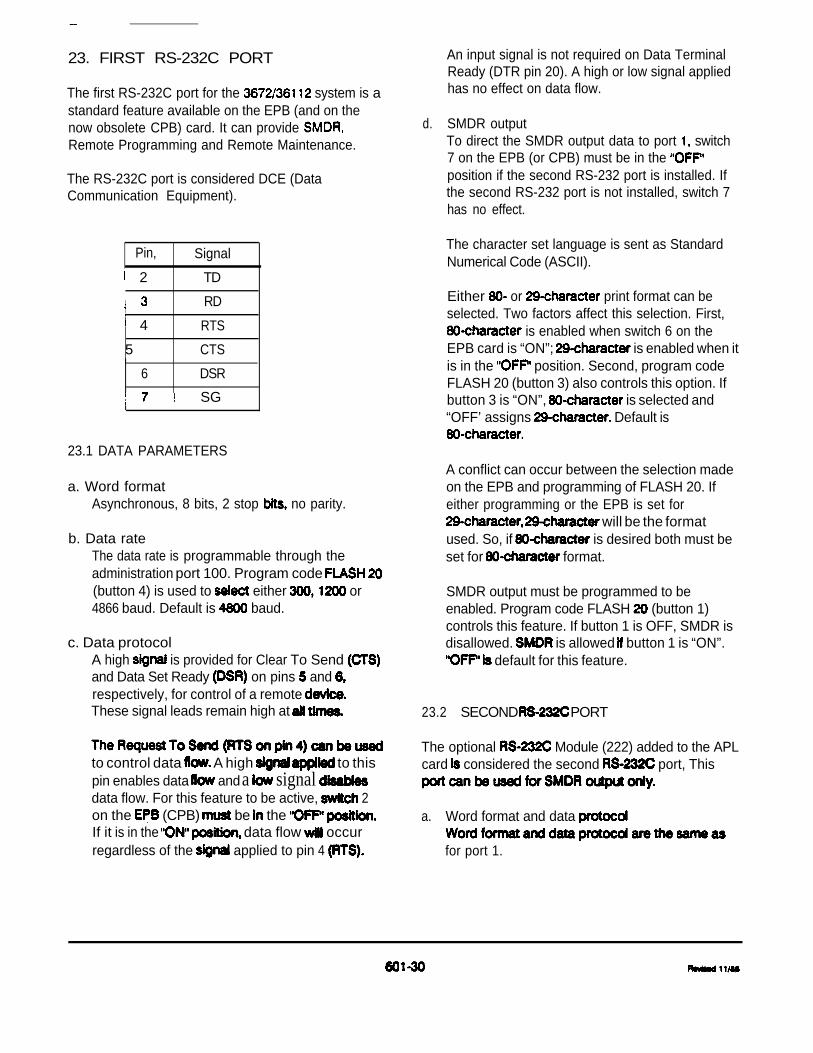
23. FIRST RS-232C PORT
The first RS-232C port for the system is astandard feature available on the EPB (and on thenow obsolete CPB) card. It can provide Remote Programming and Remote Maintenance.
The RS-232C port is considered DCE (DataCommunication Equipment).
Pin, Signal
2 TD
RD
4 RTS
5 CTS
6 DSR
SG
23.1 DATA PARAMETERS
a. Word formatAsynchronous, 8 bits, 2 stop no parity.
b. Data rateThe data rate is programmable through theadministration port 100. Program code (button 4) is used to either or4866 baud. Default is baud.
c. Data protocolA high is provided for Clear To Send and Data Set Ready on pins and respectively, for control of a remote These signal leads remain high at
to control data A high to thispin enables data and a signal data flow. For this feature to be active, 2on the (CPB) be the If it is in the data flow occurregardless of the applied to pin 4
d.
An input signal is not required on Data TerminalReady (DTR pin 20). A high or low signal appliedhas no effect on data flow.
SMDR outputTo direct the SMDR output data to port switch7 on the EPB (or CPB) must be in the position if the second RS-232 port is installed. Ifthe second RS-232 port is not installed, switch 7has no effect.
The character set language is sent as StandardNumerical Code (ASCII).
Either or print format can beselected. Two factors affect this selection. First,
is enabled when switch 6 on theEPB card is “ON”; is enabled when itis in the position. Second, program codeFLASH 20 (button 3) also controls this option. Ifbutton 3 is “ON”, is selected and“OFF’ assigns Default is
A conflict can occur between the selection madeon the EPB and programming of FLASH 20. Ifeither programming or the EPB is set for
will be the formatused. So, if is desired both must beset for format.
SMDR output must be programmed to beenabled. Program code FLASH (button 1)controls this feature. If button 1 is OFF, SMDR isdisallowed. is allowed button 1 is “ON”.
default for this feature.
23.2 SECOND PORT
The optional Module (222) added to the APLcard considered the second port, This
a. Word format and data
for port 1.

SECOND RS-232C PORT (CONT’D)
b. outputTo direct the output data to 2, 7 on the EPB must be in the “ON” position. Switch2 on the EPB has no effect on the flow (RTS) of port 2.
The also has a switch (switch 5) whichenables output. Once again, both thesystem program (FLASH 20) and EPB switch must both be to enable SMDR.
c. Data rateData rate is not chosen by programming codeFLASH 20 (button 4). Baud rate is byswitch settings on the RS-232C module. 300,
or baud can be chosen.
RS-232C port 1 is located on the front edge of theEPB. Port 2 is located on the front edge of theAPL Because physical clearance between the
a D-subminiature connector a lowprofile hood with a right angle exit issuggested.
23.3 CABLE INTERFACE TO PRINTERS ANDTERMINALS
When making an interface cable to connect aprinter/terminal to an RS-232C port on the ENCORECX system, fdlow the guidelines below:
a.
b.
C.
d.
Use the recommended connector for boththe ENCORE CX and the printer/terminal.
Only connect pins and jumpers that will actuallybe used.
Fdlow the recommendation of the printer/terminalmanufacturers for the proper cable requirements,such as gauge, twisted pairs, stranded wire,shielding and maximum length.
Use the EIA busy signal is provided from theprinter/terminal) to control data flow from theSMDR port. A high signal applied to pin 4 (RTS)on the SMDR port indicates the printer/terminal isready and a low signal means busy. If this controlis not provided from the printer/terminal, use 300baud to reduce the chances of exceeding theprinter’s buffer capacity and losing call records.
Set up the printer/terminal parameters to matchthe ones provided in the ENCORE CX systems.

2 3 . 4 EXAMPLE 1 : OKIDATA 62A WITH 23.6 EXAMPLE 2: PANASONIC PORTABLELOW SPEED INTERFACE TERMINAL (USING EIA PORT)
CABLING CONNECTIONS CONNECTIONS- -- .
KSU
Signal Pin
PRINTER
Pin signal
RD 3------- > 3RTSCTS 5 CTSSG 7- - - - - -7 SGDTR - 2 0 DTR
KSU TERMINAL I
Signal Pin Pin Signal
TDRD 3
RD
RTS 2 n d RTS I5 5
SG SGDTR 20 DTR
PRINTER SETUP
Dip Back DipSwitch Switch S P - 2
I OFF Sl A A A
S2 OFF, S3 OFF OFF S4 ON
ON OFF S6 OFF S6 OFF
S7 OFF S6 ON
23.7 TERMINAL SETUP
Set the terminal parameters as follows:
23.5 KSU SETUP
a. Set baud rate for 1200.
b. Turn on SMDR.
l-1200l - 63 -M4 - N5 - N6 - N7 -N8 -N9 - N10-211 12-L13-N
c. Set for printing.
d . OFF for SMDR output to be toRS-232C port 1 on the card. 2
SMDR output to be directed to port 2on the APL card.
23.8 KSU SETUP
See Example 1.
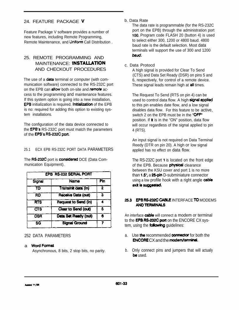
24. FEATURE PACKAGE
Feature Package V software provides a number ofnew features, including Remote Programming,Remote Maintenance, and Call Distribution .
25. REMOTE PROGRAMMING ANDMAINTENANCE: AND CHECKOUT PROCEDURES
The use of a terminal or computer (with com-munication software) connected to the RS-232C porton the EPB can both on-site and ac-cess to the programming and maintenance features.If this system option is going into a new installation,
initialization is required. of the EPBis no: required for adding this option to existing sys-tem installations.
The configuration of the data device connected tothe RS-232C port must match the parametersof the
25.1 ECX EPB RS-232C PORT DATA PARAMETERS
The port is DCE (Data Com-munication Equipment).
252 DATA PARAMETERS
a Asynchronous, 8 bits, 2 stop bits, no parity.
b. Data RateThe data rate is programmable (for the RS-232Cport on the EPB) through the administration port
Program code FLASH 20 (button 4) is usedto select either 300, 1200 or 4800 baud. 4800baud rate is the default selection. Most dataterminals will support the use of 300 and 1200
c. Data ProtocdA high signal is provided for Clear To Send(CTS) and Data Set Ready (DSR) on pins 5 and6, respectively, for control of a remote device.These signal leads remain high at times.
The Request To Send (RTS on pin 4) can beused to control data flow. A high to this pin enables date flow, and a low signaldisables data flow. For this feature to be active,switch 2 on the EPB must be in the position. If is in the “ON” position, data flowwill occur regardless of the signal applied to pin4 (RTS).
An input signal is not required on Data TerminalReedy (DTR on pin 20). A high or low signalapplied has no effect on data flow.
The RS-232C port is located on the front edgeof the EPB. Because clearancebetween the KSU cover and port 1 is no morethan a D-subminiature connectorusing a low profile hook with a right angle
INTERFACE MODEMS
An interface will connect a modem or terminalto the on the ENCORE CX sys-tem, using the guidelines:
a. Use recommended for both the CX and the
b. Only connect pins and jumpers that will actually used.

25.3 EPB RS-232C CABLE INTERFACE
Follow the recommendation of the modem orterminal manufacturer for the proper cablerequirments, such a gauge, twisted pairs,stranded wire, shielding and maximum length.
d. Use the EIA busy signal (if is provided from themodem or terminal) to control data flow from theEPB port. A high signal applied to pin 4(RTS) on the RS-232C port indicates the modemor is ready and a low signal meansbusy. If this control is not provided from themodem or terminal, use 300 baud to reduce thechances of exceeding buffer capacity.
e. Sat the modem or terminal parameters to matchthe ones provided in the ENCORE CX systems.
25.4 USING SMDR AND REMOTE PROGRAMMING
System setup to support both and RemoteProgramming/Maintenance features requires that theSMDR data be directed to the second RS-232C portof the ECX system. This port is provided on the APLcard using the optional RS-232C module (232) whichis required for this application.
a.
b.
c.
To direct the SMDR output data to port 2,switch 7 on the EPB must be in the “ON”position. Switch 2 on the EPB has no effect onthe flow control (RTS) of port 2.
The EPB also has a switch 5) whichenables output. Both the system program(FLASH 20) and EPB switch 5 must be to
SMDR.
Data rate is not by code 20 (button 4). Baud rate
communications through 2 selected byswitch settings on the module.
s2 s3 S4 ! BAUD
OFF/ 300
OFF/ ON OFF OFF 1200
OFF;
OFF OFF ON 9600
For additional information and examples for using thesecond RS-232C port, refer back to page 30 of thissection.
26. OFF-SITE DATA TERMINALPROGRAMMING FOR THE ECX3672136112
The ECX system can be remotely programmed froma data terminal interfaced to the ECX system througha modem connected to a single line telephone port orcentral office line.
The ECX system can be programmed to direct a dedi-cated incoming CO line ring to a single line telephoneport. The modem is then connected to the SIB boardcircuit that is programmed to ring. The modem theninterfaces to the EPB using an cable.
The telephone number is then dialed rings theSIB port and is automatically answered by themodem. Connection is then made to the ECX systemby the modem through the EIA cable connections onthe
The remote caller is now connected, using a data ter-minal or computer, through a end modem or
coupler to the ECX for programming.
26.1 EXAMPLE 1: HAYES CONNECTIONS
CO line (SIB port) connection and the EIA port con-nection.
The single telephone station port is connected tothe LINE” jack of the HAYES Smartmodem with a
male mod-to-mod line cord.
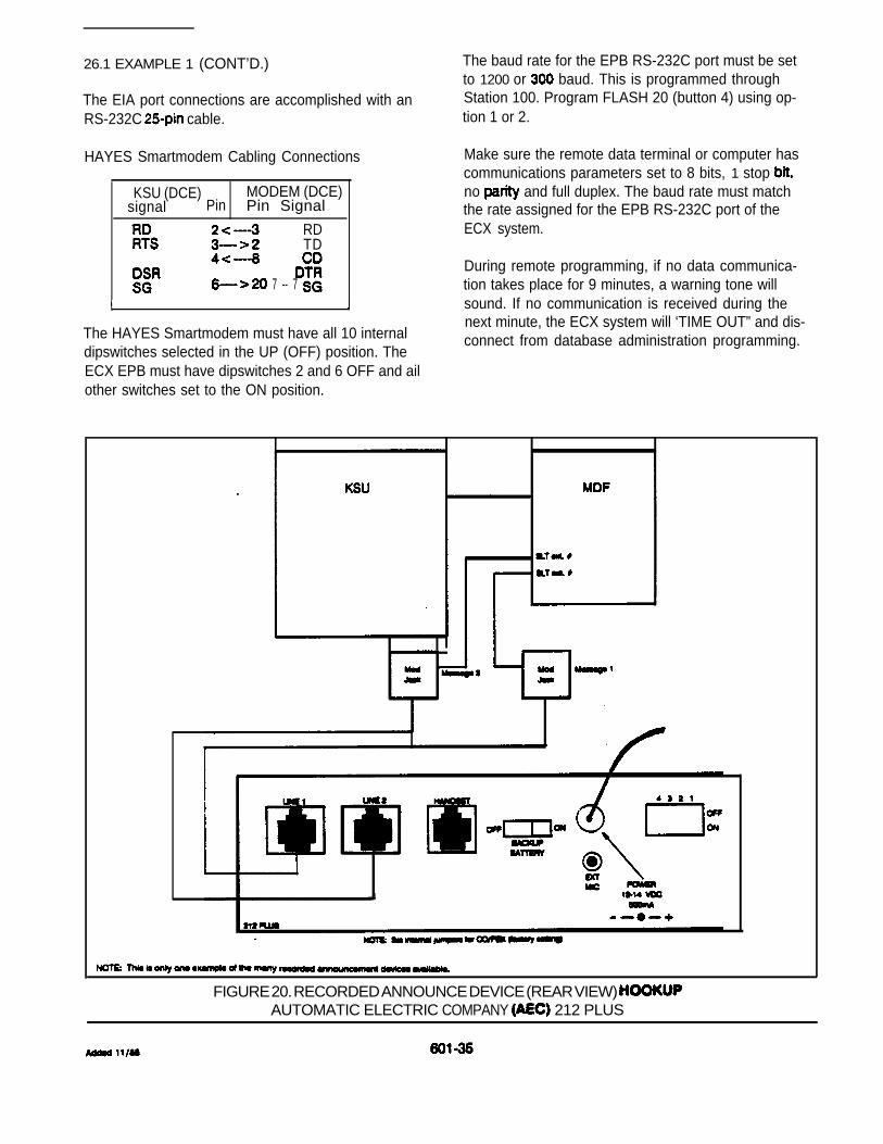
26.1 EXAMPLE 1 (CONT’D.)
The EIA port connections are accomplished with anRS-232C cable.
HAYES Smartmodem Cabling Connections
KSU (DCE) MODEM (DCE)signal Pin Pin Signal
TD RDTD
7 -- 7
The HAYES Smartmodem must have all 10 internaldipswitches selected in the UP (OFF) position. TheECX EPB must have dipswitches 2 and 6 OFF and ailother switches set to the ON position.
The baud rate for the EPB RS-232C port must be setto 1200 or baud. This is programmed throughStation 100. Program FLASH 20 (button 4) using op-tion 1 or 2.
Make sure the remote data terminal or computer hascommunications parameters set to 8 bits, 1 stop no and full duplex. The baud rate must matchthe rate assigned for the EPB RS-232C port of theECX system.
During remote programming, if no data communica-tion takes place for 9 minutes, a warning tone willsound. If no communication is received during thenext minute, the ECX system will ‘TIME OUT” and dis-connect from database administration programming.
FIGURE 20. RECORDED ANNOUNCE DEVICE (REAR VIEW) AUTOMATIC ELECTRIC COMPANY 212 PLUS

39 I IL I
FIELD CONVERSION KIT ISSUE 1, JULY 1988
ENCORE CX 36112 INSTALLATION INSTRUCTIONS
TABLE OF CONTENTS
DESCRIPTION PAGE
1. INSTALLING THE 36112 FIELD CONVERSION KIT . . . . . . . . . . . . . . . . . . . . .1.1 INSTALLING THE EXPANSION KSU . . . . . . . . . . . . . . . . . . . . . . . . . . . . . . . . . 1
2. EXPANDED INTERFACE BOARD .. . . . . . . . . . . . . . . . . . . . . . . . . . . . . . . . . . . . . . 3
3. BACKUP .. . . . . . . . . . . . . . . . . . . . . . . . . . . . . . . . . . . . . . . . . . . . . . . . . . . . 3
4. KTU PROGRAMMING .. . . . . . . . . . . . . . . . . . . . . . . . . . . . . . . . . . . . . . . . . . . . . . . . . 3
LIST OF FIGURES
1. INSTALLATION LAYOUT AND DIMENSIONS . . . . . . . . . . . . . . . . . . . . . . . . . . . . . . 42. INSTALLING CABINET STRAPS . . . . . . . . . . . . . . . . . . . . . . . . . . . . . . . . . . . . . . . . . . 43. RIBBON CONNECTION CABLES . . . . . . . . . . . . . . . . . . . . . . . . . . . . . . . . . . . . . . . . . 54. CONNECTING POWER SUPPLY TO DC/DC CONVERTER . . . . . . . . . . . . . . . . . . 55. ENCORE CX 36112 KSU . . . . . . . . . . . . . . . . . . . . . . . . . . . . . . . . . . . . . . . . . . . . . . . . . .
602-A

FIELD CONVERSION KIT ISSUE 1, JULY 1988
ENCORE CX 36112 INSTALLATION INSTRUCTIONS
1. INSTALLING THE 36112 FIELDCONVERSION KIT
1.1 INSTALLING THE EXPANSIONKSU
The 36112 Expansion KSU can beinstalled, at the same time as theBasic KSU or at a later time. Ineither case the system power must beturned off prior to the installation.
a.
b.
C.
Refer to Section 601, paragraph 3of the Technical Manual: KSUmounting. The 36112 ExpansionKSU mounts directly on top of theBasic KSU. There is also a powercage which mounts to the right ofthe Basic KSU. See Figure 1. Ifyou are upgrading a previouslyinstalled 3672 system, you mustfirst remove the 3672 Expansioncabinet pr ior to instal l ing the36112 power cage. Mark thelocation of the screws for thepower cage and the Expansion KSU.Insert the screws and tightenenough to support the weight ofthe 2 units.
Remove the connector cover on theright side of the Basic KSU.Remove the last 3 cards in theBasic KSU (slots 7, 6, 9).
There are 3 ribbon cables thatconnect to the 36112 Expansioncabinet. Feed the 3 ribboncables through the slot createdby removing the side cover, andplug them into the Basic KSU.The cables are keyed to preventthem from being installedincorrectly.
d. Feed the ribbon cables throughthe left side of the powercabinet and out the top. Securethe power cage to the Basic KSUby hooking the mounting bracketson the left side of the powercage over the ones on the rightside of the Basic KSU, and atthe same time position the powercage over the 2 screws insertedin step “a”. Tighten the screwson the right side of the powercage to secure it to the walland to the Basic KSU.
e. Mount the Expansion cabinetdirectly on top of the Basic KSUand power cage and position overthe 4 screws inserted in step“a”. Be sure the ribbon cables are stuffed back into the powercab ine t p r i o r t o p l ac i ng t he36112 Expansion KSU on the Basiccabinet. Make sure theexpansion power cord andconnector are fed through thetop of the power cabinet.Locate the two cabinet strapsand place them on both sides ofthe KSU and secure them withscrews. Figure 2. Tighten thescrews into the backboard hold the Expansion cabinetsecurely in place.
662-l

SECTION 602 ENCORE 36112 INSTALLATION INSTRUCTIONSISSUE 1. JULY 1988
1.1 INSTALLING THE EXPANSIONKSU (CONT’D)
f. Feed the ribbon cables throughthe top of the power cabinet andthrough the slot at the bottom ofthe Expansion KSU. Pu l l thecables’ up through the powercabinet and into thebackplane of Expansioncabinet. Analog cable shouldbe plugged in first followed byana log cab le L a s t i n s t a l lthe digital communication cable.See Figure 3. Cables should beinserted carefully and securely.Install the ribbon cable retaineron the left side of the DC/DCspace se’parator. Place ther ibbon cables into the plast icretainer and slide the cap on.Expansion cables should now be ina position not to interfere withany cards being plugged in.
g. Take the inter-cabinet power corda n d c o n n e c t o r f o u n d i n t h eExpansion KSU and pull throughthe same slot as the ribboncables. Plug into the right rearon the inside of the Basic KSU.
h. Remove the existing power cordplug from the left side of theBasic KSU. Take the AC cord fromthe power cabinet (female end)and route it through the top ofthe power cabinet into the 36112Expansion cabinet. Feed itacross the bottom of the KSU andout the le f t s ide . Secure thecord with a cable tie on theinside left side. Take the
end of the AC cord andinsert into the justremoved. The power cord to theAC is now plugged into the right
side of the power cage. Do notplug into the AC outlet at thistime.
i. Connect the ground of the BasicKSU to the ground of theExpansion KSU with or largergauge wire. Ca re shou ld betaken in routing the ground wireto ensure that it doesn’tinterfere with anything in thecabinet.
install the second DC/DCconverter into its slot in the36112 Expansion cab ine t . I tshould be connected to the thirdpower supply. The two wires (15inch fo r do ing so areincluded in the Expansion KSU.
t h e r e d w i r e t o t h eB+ 24V terminal on the DC/DCconverter and the black wire tothe BGND terminal on the DC/DCconverter. See Figure 4. ADC/DC converter with BCB(Battery Charging Board) shouldbe installed if complete systembattery backup is desired.
k. Re-instal l any cards removedfrom the Basic KSU. install therequired cards into the 36112Expansion KSU.
Ensure the converteron/off switches (both Basic andExpansion) are turned off. Plugthe AC cord into the ACelectrical outlet.
NOTE: The (Expanded InterfaceBoard) is an extension of the EPB.The should be installed beforeturning power on. This will allowthe EPB to recognize it as part ofthe power-up sequence. The EIBcannot be inserted or removed underpower.

ISSUE 1. JULY 1988
2. EXPANDED INTERFACE BOARD
The is equipped with light blueejector tabs and is installed in cardslot 13 of the Expansion KSU. Thiscard is r e q u i r e d t o supportadditional intercom paths andstation numbers above 155. The is an’ extension of the processor capabilities.
3. BATTERY BACKUP
If complete system battery backup isdesired, both DC/DC converters mustcome equipped with BCB (BatteryCharging Board). See Sec. 601,paragraph 6 for details on installingbattery backup. One set of batteriescan be used with 2 jumper leads toconnect to both DC/DC converters.
4. KTU PROGRAMMING
Refer to Section 601, paragraph 7.The EPB contains the same DIPswitches as described for the CPBand they should be positioned asdescribed in Section 9001901. The
also the same function asdescr ibed in Sect ion 901 for the CPB.
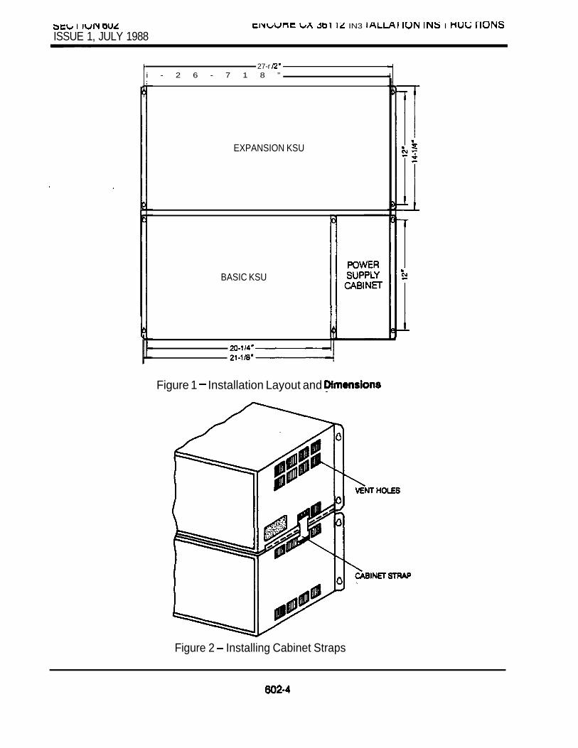
I
ISSUE 1, JULY 1988 IN3 I
27-r i - 2 6 - 7 1 8 ”
EXPANSION KSU
BASIC KSU
Figure 1 Installation Layout and
Figure 2 Installing Cabinet Straps

ISSUE 1, JULY 1988
EXPANSION KSU
Figure Ribbon Connection
WIRE
RED WIRE
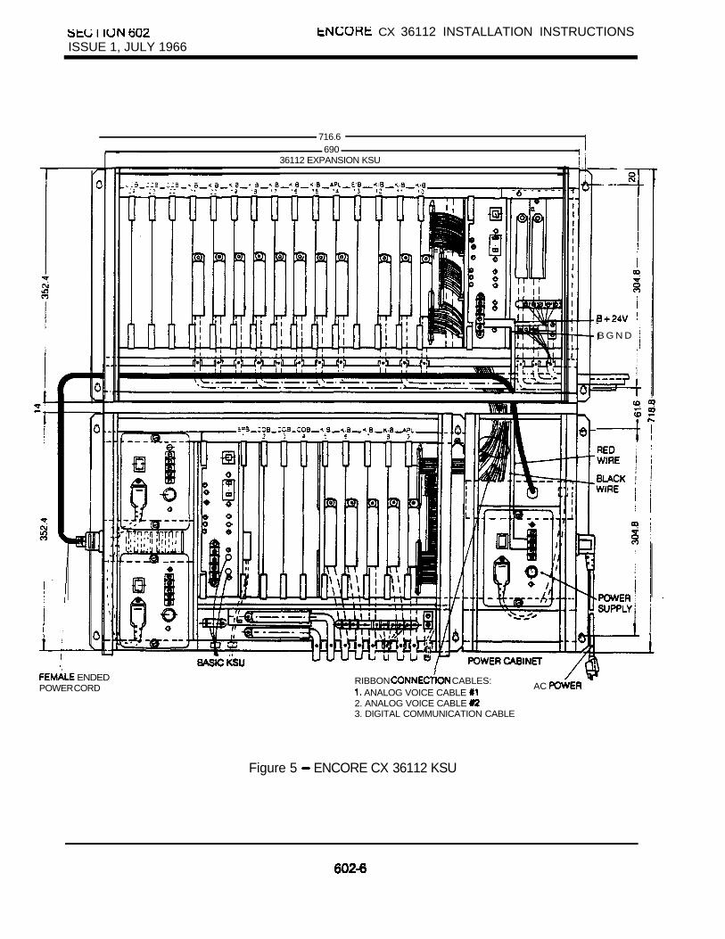
I CX 36112 INSTALLATION INSTRUCTIONSISSUE 1, JULY 1966
716.6 I690
36112 EXPANSION KSU
ENDED RIBBON CABLES:POWER CORD ANALOG VOICE CABLE
AC
2. ANALOG VOICE CABLE 3. DIGITAL COMMUNICATION CABLE
Figure 5 ENCORE CX 36112 KSU
B G N D

LX b I KEY TELEPHONE SYSTEM ISSUE MAY 1987
ENCORE CX 816 SYSTEM PROGRAMMING PROCEDURES
TABLE OF CONTENTS
1.
5.
8.
7.
9.
10.
DESCRIPTION PAGE
INTRODUCTION. . . . . . . . . . . . . . . . . . . . . . . . . . . . . . . . . . . . . . . . . . . . . . . . . . . . . . . . . .
PROGRAMMING PROCEDURES. . . . . . . . . . . . . . . . . . . . . . . . . . . . . . . . . . . . . . . . . . . 4
2.1 PROGRAM MODE ENTRY . . . . . . . . . . . . . . . . . . . . . . . . . . . . . . . . . . . . . . . . . . 4. . . . . . . . . . . . . . . . . . . . . . . . . . . . . . . . . . . . . . . . . . . . . . . . . . . . . 5
SYSTEM PARAMETERS PROGRAMMING . . . . . . . . . . . . . . . . . . . . . . . . . . . . . . . . . . 6
CO LINE PROGRAMMING . . . . . . . . . . . . . . . . . . . . . . . . . . . . . . . . . . . . . . . . . . . . . . .
STATION PROGRAMMING . . . . . . . . . . . . . . . . . . . . . . . . . . . . . . . . . . . . . . . . . . . . . . . .
EXCEPTION TABLES PROGRAMMING . . . . . . . . . . . . . . . . . . . . . . . . . . . . . . . . . . . .
SPECIAL TABLES PROGRAMMING . . . . . . . . . . . . . . . . . . . . . . . . . . . . . . . . . . . . . . . 1
PRINT ROUTINES . . . . . . . . . . . . . . . . . . . . . . . . . . . . . . . . . . . . . . . . . . . . . . . . . . . . . . .
PROGRAMMING SYSTEM SPEED NUMBERS . . . . . . . . . . . . . . . . . . . . . . . . . . . . . .
PROGRAM
DEFAULT VALUES. . . . . . . . . . . . . . . . . . . . . . . . . . . . . . . . . . . . . . . . . . . . . . . . . . . . . . . . . 2 OF SERVICE. . . . . . . . . . . . . . . . . . . . . . . . . . . . . . . . . . . . . . . . . . . . . . . . . . . . . .
ALLOW/DENY RULES. . . . . . . . . . . . . . . . . . . . . . . . . . . . . . . . . . . . . . . . . . . . . . . . . . . . . . 21
LIST OF FIGURES
1. EXECUTIVE TELEPHONE. . . . . . . . . . . . . . . . . . . , . . . . . . . . . . . . . . . . . . .
700-A
.

KEY TELEPHONE SYSTEM
ISSUE MAY 1897
ENCORE CX 816 PROGRAMMING PROCEDURES
1. INTRODUCTIONThe ENCORE CX 816 Key Telephone System canbe programmed to meet each customer’s individualneeds. All programming is done at station 100 usinga key telephone. This can be done with either a button or non-display telephone. However,using a display phone will make programming easier.This display will indicate what features are beingprogrammed and the current programming of thesefeatures. When data is changed, this will bedisplayed so you can see what has been entered.
Upon entering the program mode, the ENCORE CXKey Telephone at station 100 no longer operates asa telephone but as a programming instrument with allof the buttons redefined. The keys of the dial padare used to enter the various data fields and to enternumerical information such as timers. The 12 buttonslocated at the top of the phone (Program Buttons)are used to program features such as class ofservice, line groups, station features, toll restrictiontables, .etc. (Figure 1)
At the time the system is installed, upon entering theprogram mode, the system MUST be initialized toload default data into memory. See Table 1 fordefault data. If this preprogramming suits thecustomer, initialization is all that is needed.
Any time data is to be changed, the program modemust be entered and then the individual programcode. Use program codes to determine currentprogramming or to change a specific feature.
During programming other operate normally.If a program code is used to determine programmingbut nothing is changed (or changed but not enteredinto memory by pressing HOLD), the previous datawill remain intact upon leaving the field. Programcodes do not have to be used in any particular order.When programming, tones are provided to help theprogrammer determine correct or incorrect entry ofdata. A solid tone indicates the data was accepted.An interrupted tone means an error was made.When this occurs, re-enter the data. Until new datais entered and accepted, the system will continue tooperate under default or previously programmedvalues.
The ENCORE CX 816, unlike the 3672, has notemporary buffer area where data is stored duringprogramming. Data is entered permanently into thedata base when the HOLD button is pressed.It is not necessary to use FLASH 80.
700-l

Customer worksheets should be filled out before programming begins. Go through the following instructionsand explanations step-by-step and fill out all worksheets before attempting to program the system.
TABLE 1. DEFAULT VALUES
FEATURE PROGRAM CODE VALUE
System Hold Recall Timer Flash 01 060 sec.Exclusive Hold Recall Timer Flash 02 180 sec.Transfer Recall Timer Flash 03 045 sec.
“‘Preset Forward Timer Flash 04 10 sec.Pause Timer Flash 05 2 sec.Call Park Timer Flash 06 180 sec.Conference T imer Flash 07 10 min.
Wait Reminder Tone Flash 08 000 min.Paging Timeout Timer Flash 09 15 sec.CO Ring Detect Timer Flash 10 3 (100 msec.)Hold Preference Flash 11 SystemAutomatic Privacy Flash 12 YesLoud Bell Operation for UNA Flash 13 Off
l Attendant Override Flash 14 . YesAttendant Station Assignment Flash 15 100Loud Bell Control Flash16 NonePBX Dialing Codes Flash 17 None
Transfer Flash 18 (Buttons l-4) NoneStation Hunt Groups Flash 19 (Buttons l-8) NoneSMDR (ON.OFF) Flash 20 (Button 1) off
Call Type (Button 2) Long Dist.Print Format (Button 3)Baud Rate (Button 4) 300Forced Account Codes (Button 5)
l * Alarm ON/OFF Flash 21 (Button 1)Signaling (Button 2) OnceLoop Detect (Button 3) Closed
Dii Pulse Ratio Flash 22 (Button 1)(break/make)
Dial Speed (Button 2) l Access Code’ Flash 24 None
Intercom Box Timer Flash 25 20l Dedicated Attendant Intercom Path Flash 26 No
Music Channels Flash 27 1Setting Time and Date Flash 28 None
l Monitor Mode Flash 29 No
.l ENCORE CX 3672 only
l * ENCORE CX 816 onlyl m* Also controls ring time in CX 3672 system

MAY 1987
TABLE 1. DEFAULT VALUES (CONT’D)
FEATURE PROGRAM CODE
CO Line Attributes Flash 30 Pulse (Button 1)
(Button 2)UNA (Button 3)
l Loop Supervision (Button 4)l (Button 5)
Flash Timer (Button 6)CO tine Group (Button 7)Line COS (Button 8)
l Hook Switch Timer Flash 31l Hook Switch Bounce Timer Flash 32
Attendant Recall Timer Flash 33Station Attributes Flash 40
Paging Access Page A (Button 1)DND Access (Button 2)System Speed Access (Button 3)Queuing Access (Button 4)Preferred Line Answer (Button 5)
‘OHVA (Button 6)Call Forward Access (Button 7) Alarm Signal (Button 8)Station Type Page B (Button 1)Station Class of Service (Button 2)Speakerphone Operation (Button 3)Group Pickup Assignment (Button 4)Paging Zone Assignment (Button 5)Preset Assignment (Button 6)CO Line Group Access (Button 7)CO Line Button Assignment (Button 8)
Exception Tables Flesh 50Allow Table A (Button 1)Deny Table A (Button 2)Allow Table B (Button 3)Deny Table B (Button 4)Special 1 (Button 5)Special Table 2 (Button 6)Special Table 3 (Button 7)Special Table 4 (Button 8)
VALUE
DTMFc oYesNoNo20
11
1 sec.010 msec.
01 min.
YesYesYesYesNoNo
YesNo
01011
None
NoneNoneNone
AllAllAllAll
l 3672 onlyl * ENCORE CX 816

MAY 1987
2. PROGRAMMING PROCEDURES
2.1 PROGRAM MODE ENTRYProgramming is done at station 100 usingpreferably a or display telephone.Programming is always done at this stationregardless of attendant assignment or class ofservice.
To enter the program mode, the programmer mustfirst verify that the is property connected tostation 100.
1. Go off-hook or press MON button to ON.
2. Dial an asterisk l
3. Dial (PROG).Confirmation tone is heard.l l Initialize system data base at this point
(ENCORE CX 816 must be initialized inprogramming; see paragraph 2.2)
4. Press FLASH button. Dial 2-digit program code.
6. Enter data.
7. Press HOLD. (Confirmation tone)
All data is now stored in permanent memory and willaffect system operation.
EXECUTIVE TELEPHONE
700-4

ISSUE MAY 1987
2.2 The system has been pre-programmed with certainfeatures which are called default data. (Table 1)These features are loaded into memory when thesystem is initialized. The system should ALWAYSbe initialized when installed or at any time the database has been corrupted. To initialize the systemto default
ENCORE CX 816Repeat the procedures explained below for each ofthe data base areas.
1.
2.
3.
Enter the programming mode.
Press button.Dial 60 to initialize system parameters.
4.
5.
Press HOLD button.
Repeat from step 2 for the other areas.In step 3 use the following program codes.60 for system parameters61 for CO lines62 for station parameters63 for exception tables.64 for system speed numbers
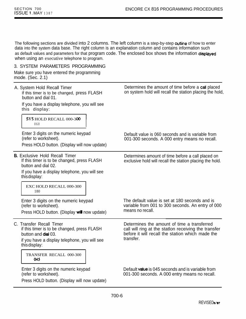
SECTION 700ISSUE MAY 1 3 8 7
ENCORE CX 816 PROGRAMMING PROCEDURES
The following sections are divided into 2 columns. The left column is a step-by-step of how to enterdata into the system data base. The right column is an explanation column and contains information suchas default values and parameters for that program code. The enclosed box shows the information when using an executive telephone to program.
3. SYSTEM PARAMETERS PROGRAMMINGMake sure you have entered the programmingmode. (Sec. 2.1)
A. System Hold Recall TimerIf this timer is to be changed, press FLASHbutton and dial 01.
Determines the amount of time before a placedon system hold will recall the station placing the hold,
If you have a display telephone, you will seethis display:
HOLD RECALL 000-3000 6 0
Enter 3 digits on the numeric keypad(refer to worksheet).Press HOLD button. (Display will now update)
Default value is 060 seconds and is variable from001-300 seconds. A 000 entry means no recall.
Exclusive Hold Recall TimerIf this timer is to be changed, press FLASHbutton and dial 02.
Determines amount of time before a call placed onexclusive hold will recall the station placing the hold.
If you have a display telephone, you will seethis display:
EXC HOLD RECALL 000-300180
Enter 3 digits on the numeric keypad(refer to worksheet).Press HOLD button. (Display now update)
The default value is set at 180 seconds and isvariable from 001 to 300 seconds. An entry of 000means no recall.
C. Transfer Recall Timerif this timer is to be changed, press FLASHbutton and 03.if you have a display telephone, you will seethis display:
Determines the amount of time a transferredcall will ring at the statlon receiving the transferbefore it will recall the station which made thetransfer.
TRANSFER RECALL 000-300
Enter 3 digits on the numeric keypad(refer to worksheet).Press HOLD button. (Display will now update)
Default is 045 seconds and is variable from001-300 seconds. A 000 entry means no recall.
700-6REVISED

ENCORE CX 816 PROGRAMMING
ISSUE 1. MAY 1987
D. Preset Forward Timer Determines the amount of time an outside line willIf this timer is to be changed, press FLASH ring before being forwarded to a predeterminedbutton and dial 04. station. This entry works with Preset ForwardIf you have a display telephone, you will see assignments in station attributes. More than onethis display: station can be forwarded to the same destination.
PRESET TIMER 00-991 0
NOTE: This timer also controls the lengthof time a call will ring at astation.
Enter 2 digits on the numeric keypad(Refer to worksheet).
Press button. (Display will now update)
Default time is set at 0 seconds and is variablefrom seconds. A 00 entry means no forward.
E. Pause TimerIf this timer is to be changed, press FLASHbutton and dial 05.
Determines the length of the pause for use withautomatically sent digits or other speed dialing.
If you have a display telephone, you will seethis display:
PAUSE TIMER2
Enter 1 digit on the numeric keypad(refer to worksheet).
Press HOLD button. (Display will now
Default is 2 seconds and is variable from l-9seconds. There is no 0 entry.
F. Call Park Recall TimerIf this timer is to be changed, press FLASHbutton and dial 06. you have a display telephone, you will see
this display:
Determines the amount of time before a placedin a call park location will recall the station placing
CALL PARK 180
Enter 3 digits on the numeric keypad(refer to worksheet).Press HOLD button. (Display will now update)
Default is 160 seconds and is variable from001-600 seconds. A 000 entry means no recall.

ISSUE MAY 1987
G. Conference TimerIf timer is to be changed, press FLASHbutton and dial 07.If you have a display telephone, you will seethis display:
Determines the amount of time an unsupervisedconference can continue after the initiator of theconference has exited the conference.
CONFERENCE TIMER 00-99
Enter 2 digits on the numeric keypad(refer to worksheet).
Press HOLD button. (Display will now update)
Default is 10 minutes and is variable from minutes. A 00 entry means no disconnect.
H. Message Waiting Reminder ToneIf this timer is to be changed, press FLASHbutton and dial 08.If you have a display telephone, you will seethis display:
Determines the amount of time between repeatedreminder tones to a telephone with a messagewaiting.
TONE ooo-104ooo
Enter 3 digits on the numeric keypad(refer to worksheet).
Default is 000 (disabled) and is variable from000-l 04 minutes.
Press HOLD button. (Display will now update)
Paging Timeout Timer Determines the maximum length of a page.If this timer is to be changed, press The system automatically disconnect the page atbutton and dial OS. the end of this time unless the has hung up .
If you have a display telephone, you see earlier.this display:
Enter 2 digits on numeric keypad(refer to worksheet).Press (Display will now update)
Default is 15 and is from 01-60seconds. A 00 entry the and pagesare not limited in length.

ENCORE CX 816 PROGRAMMING PROCEDURES
ISSUE MAY 1987
J. CO Ring Detect TimerIf this timer is to be changed, press FLASHbutton and dial 10.If you have a display telephone, you will seethis display:
This timer controls the time necessary to detect anoutside line as ringing into the system.
CO RING DETECT 2-93
Enter 1 digit on the numeric keypad(refer to worksheet).
Press HOLD button. (Display will now update)
Default is 3 (hundred milliseconds) and is variablefrom 2-9. There is no 0 or 1 entry.
K. Hold PreferenceIf this feature is to be changed, press FLASHbutton and dial 11.If you have a display telephone, you will seethis display:
HOLD PREFERENCE SYS-EX
The system may be programmed to have eitherexclusive or system hold preferred. If exclusive holdis preferred, depress HOLD button once forexclusive hold and twice for system hold when a key telephone. If system hold is preferred,depress HOLD button once for system hold andtwice for exclusive hold.
To make a change, press the top left programbutton.It will toggle on and off with each depression.
LED off --exclusiveLED on (Watch your display)
Press HOLD button. (Display will now update)
Default is system hold.
L. Automatic Privacy this feature is to be changed, press
button and dii 12.If you have a telephone, you will seethis display:
To make a change, press the top leftProgram Button.It will toggle on and off with each depression.
LED off LED on ==yes(Watch your display)
Press HOLD button. (Display will now update)
desired, the system can be programmed toeliminate CO line privacy, allowing a maximum of cother station to join in on existing outside lineconversations. If privacy is disabled and a stationjoins an existing call in progress, both parties willhear an alert tone.
Default is yes-automatic privacy is in effect.
700-9

ISSUE MAY 1987
M. Attendant StationIf this feature is to be changed, press FLASHbutton and dial 15.If you have a display telephone, you will seethis display:
The system will identify an attendant station for thepurpose of receiving recalls and activating nightservice.
The ENCORE CX 816 can have only one attendant;the ENCORE CX 3672 can have up to 3.
ATTN STA ASSIGNMENT100,
Enter the 3-digit station number on thenumeric keypad.
Press HOLD button. (Display will now update)
By default station 100 is assigned as attendantstation. Entering 3 pounds will remove thatattendant assignment or a different station number(s)can be programmed.
N. Loud Bell ControlIf this feature is to be assigned, press FLASHbutton and dial 16.If you have a display telephone, you will seethis display:
Two stations can be assigned to Loud Bell Control.The LBC contacts will follow the ringing assignmentsof those stations.
l The second 3 digits = the station assignedto the second Loud Bell Control.
LOUD BELL CONTROL ASSIGN
NOTE: Requires optional Emergency Transfer Unit(ETU) on 3672. Maximum one ETU percabinet. One loud bell contact per ETU.
Enter the station numbers. A maximum of6 digits (2 stations) may be entered.*
Press HOLD button. (Display will now update)
By default no stations are assigned. Entering thepound will remove an assignment.
0. PBX Dial CodesIf these are to be assigned, press FLASHbutton and dial 17.If you have a display telephone, you will seethis display:
PBX DIAL CODES
J
Enter code one right after the By default no codes are assigned.other up to a maximum of 10 digits on the To delete an entry, enter two (pound) numeric keypad. and press HOLD.Press HOLD button.
Five 1 or PBX access codes can beprogrammed into memory. When dialed, these codessignal the system so that restriction is appliedat the next dialed digit. When a single-digit accesscode (9) is required, the pound must be enteredas the second digit (9
700-l 0

P. Executive/Secretary PairsIf these are to be assigned, press button and dial 18.If you have a display telephone, you will See
this display:
There are 4 sets of pairs available. When anexecutive station is busy or in DND, intercom callsand transfers will be automatically routed to thedesignated secretary.
The top left Program Button will be lit indicatingthe first pair may be entered.Enter executive station.
Enter secretary station.
Press HOLD button.
To enter a second pair, press the secondprogram button.
Enter 3-digit executive station.
Enter secretary station.Press HOLD button.
For a third pair, press third program button.
Enter executive station.
Enter station.Press HOLD button.
For a fourth pair, press fourth program button.Enter executive station.Enter secretary
Press HOLD button.
There can be only one pairing of stations no duplicates.
You cannot pair EXEC to SEC 10 1) and thenpair SEC to EXC (1 01 100). YOU can have the same
station for more than one executive station(101-100, 102-100).
An entry of pounds will remove the assignments.Individual pairs may be changed by pressing theassociated program button.
Q. Hunt GroupsIf these are to be assigned, press FLASHbutton and dii 19.If you have a telephone, you will seethis display:
HUNT GROUP
There can be 8 hunt groups of no more than 8stations each. The hunt groups use a pilot huntingtechnique. If the pilot number is dialed, the assignedstations in that hunt group are searched in the orderin which they are entered into programming. The firstidle station will be rung.
The top left program button be lit forprogramming the first hunt group.
If a specific station number is dialed, only that stationis rung; no hunting will be done if that station is busy.By default no stations are assigned to a hunt group.
700-l 1

I IUN UUISSUE MAY 1987
Enter the station numbers up to amaximum of 24 digits (8 stations).
Press HOLD button. (Display will now update)To enter further hunt groups press programbuttons as follows:
Enter station numbers.
Press HOLD button. (Display will now update)
If a station is in DND or is to anotherstation, it is considered busy.
Hunt groups can be joined together by programminganother hunt group number as the last entry insteadof a station number.To remove stations from a hunt group, enter three# (pound) signs and press HOLD. This will eraseall previous stations in that group.
The groups and pilot numbers are:Group 0= 260Group Group Group Group Group Group Group
R. SMDRIf this feature is to be used, press FLASHbutton and dial 20.If you have a display telephone, you will seethis display:
A call accounting device can be installed allowing thesystem to track calls by outside line number, numberdialed, time of day, date, station that placed orreceived the and duration of the call.
SDR TPE PNT BDR ACCNO LD 80 300 NO
To program SMDR features, use the programbuttons as follows:
These buttons toggle on and off(refer to worksheet).LED on enabled, LD only, go-character,
300 baud, mandatory acct. codes required.LED off disabled, recorded,
1200 baud, no account used.
Press HOLD button. (Display will now update)
By default SMDR ii not enabled. The system can beset to record either ail outgoing calls or only longdistance outgoing calls.
By default it is set to record long distance (LD) only.The system can be programmed to print in either an
or a format.By default the system is set to print in the character format.The baud rate for the printer can be set for either1200 baud or 300 baud (slow). Default is 300.The system can be programmed to force the use ofaccount codes in long distance calls. If option isset to on (yes), stations must an account code(up to 12 digits) in order to make long distance calls.By default this option set to off (no).
700-l 2

I I ISSUE MAY 1987
S. Alarm Signal (ENCORE CX 816 only)If feature IS to be used, press button and dial 2 1 .
If you have a display telephone, you will seethis display:
ALARM SIGNAL DETECTN O ONCE CLOSED
To program alarm features, use the programbuttons as follows:
These buttons toggle on and off.(refer to worksheet).
LED on enabled, once, closed loopLED off alarm disabled, repeated, open loop.
Press HOLD button. (Display will now update)
The system can recognize either an open or closedloop from an external source and transmit an alarmsignal to all available (non-busy) telephones with acontinuous or single tone. The type of alarm tonecan be programmed.By default the alarm is not enabled.
The signal can be either once or repeated.By default it is set at once.The loop sense can be either closed or open.By default it is set at closed.
T. Dial Pulse Parameters*If this feature is to be used, press FLASHbutton and dial 22.
If you have a display telephone, you will seethis display:
*NOTE: When used in Canada, DOC regulationsdo not allow pulse signaling speed toexceed 11 pps (pulses per second) with aminimum of 33 msec. make internal and54-66 msec. break interval.
DIAL PULSE RATIO SPEED
To program dial pulse features, use the programbuttons as follows:
By default all lines are (tone) signaling.If outpulsing is required, the individual outside linemust be programmed for pulse. See CO lineprogramming section. The break/make ratio and thedial-speed can be with this program.By default the break/make ratio is set at but can be changed to
By default the dialing speed is 10 pps but can bechanged to 20 pps.
700-l 3

SECTION 700 ENCORE CX 816 PROGRAMMING PROCEDURESISSUE 1, MAY 1987
These buttons toggle-on and off.LED on = 10 ppsLED off = 20 ppsWatch your display.
Press HOLD button. (Display will now update)
U. Intercom Box Call TimerIf this timer is to be changed, press FLASHbutton and dial 25.If you have a display telephone, you will seethis display:
Determines the amount of time programmed stationswill ring when an Intercom box user presses the
button.
B O S
Enter 2 digits on the numeric keypad Default is 20 seconds and is variable from 00-60(refer to worksheet). seconds. A 00 entry causes programmed stationsPress HOLD button. (Display will now update) to ring until the call is returned.
Setting System Time and Date(Enter FLASH 28)If you have a display telephone, you will seethis display:
DATE AND\ TIME am
Enter time and date as follows:YYMMDDHHMMSSPress HOLD button. (Display will now update)
By default system time and date is set at 00.When entering the time and date, use the followingdata:
year (YY) =OO-99month (MM) 2
hour (HH) minute (MM) second (SS) =OO-60
W. Attendant Recall (Enter FLASH 33)If you have a you seethis display:
Determines the length of the attendantwill be recalled before automatic disconnect
ATTN REC.411 TIMER 01
Enter 2 digits on the numeric keypad.Press HOLD button.
Default is 0 1 minutes Range is minutes.00 no automatic disconnect.
700-l 4

X. Monitor Mode (Group Listening)If this feature is to be changed, press FLASHand dial 29.
If you have a display telephone, you will see thefollowing:
This feature determines the use of the monitorbutton.
YES-NONO
Toggle the top left button on or off to determineprogramming.
LED on LED off = disabled
Press HOLD button.
YES means that the speakerphone can be used atthe same time as the handset is being used. Thisallows for the group listening feature.
NO means the monitor button is used to switchbetween handset and speakerphone.Default is no.
4. CO LINE PROGRAMMINGIf you are in the program mode, continue using theProgram Codes.If you are starting to program at this point, enter theprogram mode first (Sec. 2.1).
If any CO Line features are to be changed,press FLASH button and dii 30. you have a display telephone, you will see
this display:
CO ATTRIBUTESSELECT A CO LINE RANGE
Program button (SLCT will be lit. Enter a digit number for CO range being programmed.If only 1 line is being programmed, enter thatnumber twiie (i.e 0101).Press HOLD button.The display will appear like this inditing currentprogramming of that line of liis.
Each individual outside line can be programmed tobe either DTMF (tone) or dial pulse.By default all are set for DTMF.When marked a 1 or dial-code may beentered after which toll restriction is applied.By default, all lines are CO.
if a line is marked UNA, this activates night serviceanswering of incoming calls on this line bystations not normally assigned access to the line(s).The must have a loop key assigned to do so.Default is yes.
NOTE: For LOOP supervision and programming, see Section 701.
700-l 5
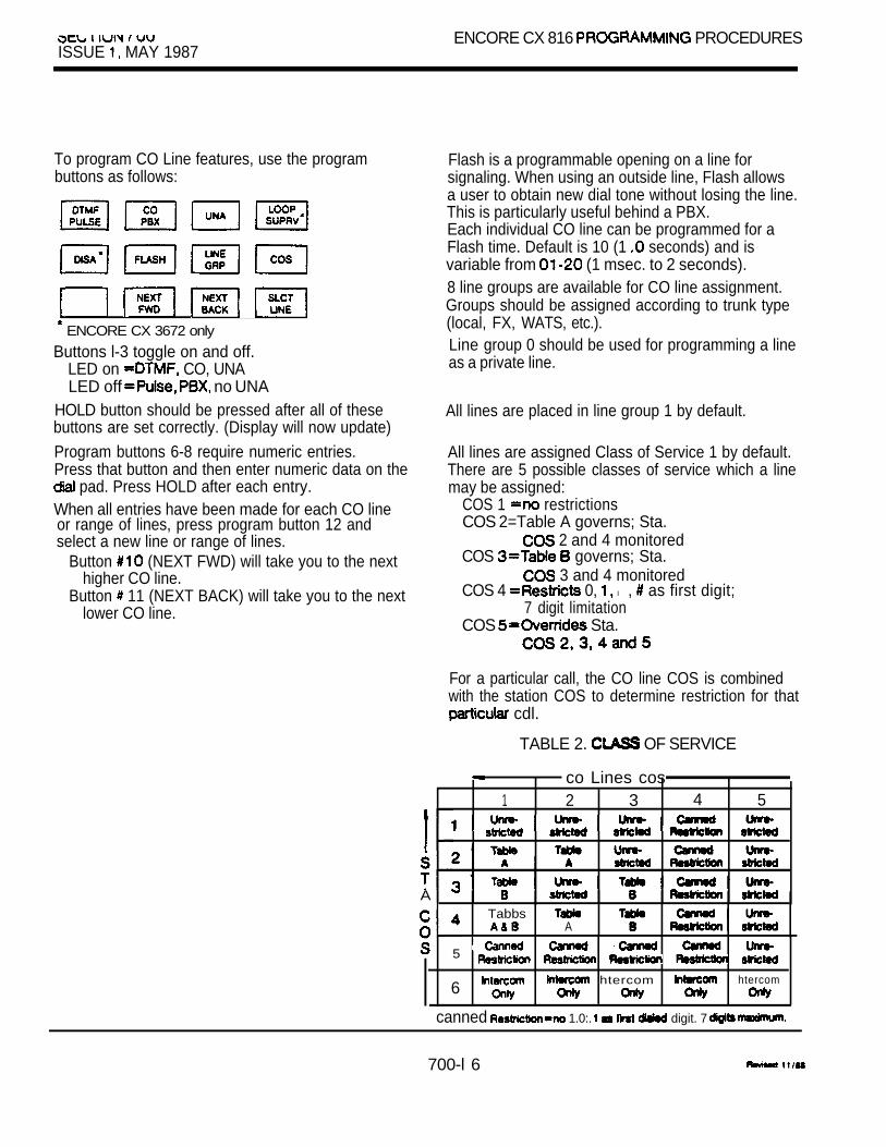
ISSUE MAY 1987ENCORE CX 816 PROCEDURES
To program CO Line features, use the programbuttons as follows:
ENCORE CX 3672 only
Buttons l-3 toggle on and off.LED on CO, UNALED off no UNA
HOLD button should be pressed after all of thesebuttons are set correctly. (Display will now update)
Program buttons 6-8 require numeric entries.Press that button and then enter numeric data on the
pad. Press HOLD after each entry.When all entries have been made for each CO lineor range of lines, press program button 12 andselect a new line or range of lines.
Button (NEXT FWD) will take you to the nexthigher CO line.
Button 11 (NEXT BACK) will take you to the nextlower CO line.
Flash is a programmable opening on a line forsignaling. When using an outside line, Flash allowsa user to obtain new dial tone without losing the line.This is particularly useful behind a PBX.Each individual CO line can be programmed for aFlash time. Default is 10 (1 seconds) and isvariable from (1 msec. to 2 seconds).8 line groups are available for CO line assignment.Groups should be assigned according to trunk type(local, FX, WATS, etc.).Line group 0 should be used for programming a lineas a private line.
All lines are placed in line group 1 by default.
All lines are assigned Class of Service 1 by default.There are 5 possible classes of service which a linemay be assigned:
COS 1 restrictionsCOS 2=Table A governs; Sta.
2 and 4 monitoredCOS governs; Sta.
3 and 4 monitoredCOS 4 0, l , as first digit;
7 digit limitationCOS Sta.
For a particular call, the CO line COS is combinedwith the station COS to determine restriction for that
cdl.
TABLE 2. OF SERVICE
co Lines cos1 2 3 4 5
A Tabbs
A
5
6 htercom htercom
canned 1.0:. digit. 7
700-l 6

ENCORE 816 PROGRAMMING PROCEDURES I IUN UU
ISSUE MAY 1987
5. STATION PROGRAMMING you are in the programming mode, continue using
the program codes.If you are starting programming here, enter theprogram mode first. ‘Refer to Section 2.1.
If station features are to be changed, press FLASHand dial 40,If you have a display telephone, you will seethis display:
STATION ATTRIBUTESSELECT A STA RANGE
Program button (SLCT STA will be lit.Enter a number for station range beingprogrammed. If only 1 station, enter that numbertwice (i.e. 101101).Press HOLD button.The display will appear like this while programmingPage A for that station or group of stations:
To program Page A features, use the buttons asfollows.
These buttons toggle on and off.LED access, DND, system speed,
queuing, ringing line preference,call forward, alarm receive.
LED off restricted, no DND,no system speed, no queuing, no ringingline preference, no forward,
The features of Page A are described as follows:
PAGE
Stations can individually be allowed or denied theability to make pages.Default allows paging access.
Stations can be individually allowed or denied theability to place their telephone in DO NOT DISTURB,Default allows DND.
E lStations can be individually allowed or denied theability to use system speed numbers.Default allows system speed.
Stations can be allowed or denied the ability ofqueue for a busy group of lines. Default allowsqueuing.
Stations can be given the ability to answer incomingoutside line calls by simply going off-hook(ringing line preference). Disallowed by default.
For Off-Hook Voice Announce (OHVA)refer to Section 701.
Stations can be allowed or denied the ability to haveintercom and transferred outside lines forwarded toa n o t h e r
Default allows Forward.
Stations can be designated to receive signalsthrough the telephone speaker. (816 only)Default gives no stations the feature.
700-l 7
ISSUE 1, MAY 1987 0 I
When the features of Page A have been selected,press HOLD. The display will now update to thenew data.
The display of current programming for thosefeatures will appear as follows:
The remaining features of the station are located andprogrammed on Page B.
Press PAGE’B SELECT button. This will UPadditional station features to be programmed.
The display of current programming for thosefeatures will appear as follows:
XXX-XXX B COS SPOAAAA BBBB CCC DDDDDDDD I
XXX rangeB pageID -station IDCOS of service
optionA pickup group
zoneC forward stationD =CO line group access
To program Page B features, use the programbuttons as follows:
These features all require a entry.Press program button and then enter thenumber via the dii Press HOLD after each numeric (Display will now update)
NOTE: When identifying a station as a DSS
number of the key telephone theDSS is associated with, not the extensionnumber that the DSS using.
The features of page B are described as follows:
STA ID
Each station must be identified as one of thefollowing:
0 1 = DSS with MAP 1 (3672136112 only)2 = DSS MAP 2 (3672136112 only)3 = DLS MAP 3 72 on/y)4 = intercom box5 = SLT or OPX 72 6 = SLT (3672136112 7 = DSS with MAP 4 (36172 only)8 = DSS MAP 5 (Feature Package V only)
By default all are 0 (keyset).
NOTE: When identifying a station as an intercomphone box (4) you must also enter thebackground music source to be used withthat intercom box.0 = none1 first source2 second source
E lEach station must be assigned a class of service
governs that station’s toll restriction.The 6 classes
1 by Table A by by Table A and B
1, l , as fit digit, 7 digits maximum
Default gives stations 1.For a the CO line combinedwith station to determine that
Each telephone’s speakerphone must beprogrammed.
normal speakerphone1 for outgoing but works for
intercom headset
Default assigns telephones to 0.
700-l8
Each station is assigned into pickup groups.Stations can be in any combination of the 4 groupsor in no group at all.
0 = no group1 1
3 4
By default all are in group 1.
Each station is assigned to internal paging zones.A station can be in any or all zones or in no zoneat all.
O-no zone (will receive no pages)1 1
2 3 ,
Default assigns ail to zone 1.Internal Ail Call is defined as the sum of all zones.If a station is not in any internal zone, it will notreceive any all call pages either.
A station can be programmed so that incomingringing outside lines can be to a presetstation if the first station does not answerafter a programmable of time. Default assignsno stat ions.NOTE: No more than 5 preset call forwards can be
in sequence. For example:101 preset to 102102 to 103103 preset to 104104 preset to 105
No more
A station is allowed access to any combination ofoutside line groups. Or a station may not be allowedany access to outside lines.The following are the line group numbers and theiraccess codes:
Group 0 = no access (for lines)Group 1 = code 9Group 2 = code 81Group 3 = code 82Group code Group code 84Group 6 code Group 7 code 86Group 8 = code 87 (816 Group 8 = code 88 + line number*
CO lines are accessed by the station user dialingthe appropriate group access code number.Dial tone will be received and they can thedesired telephone number. A station user can alsoprogram one of their flexible buttons with the codenumber and then can access that group of lines bysimply pressing a button.When using a code to access an outside line, thefast line in the group will be the first one accessedand the first line will be the last one accessed.By default all stations will be allowed access togroup 1.
l Any station with access to line group 8 canuse code to access lines in groups l-8.
To assign buttons are to be outside lines,press CO LINE button on page (Button 8)If you have a telephone, you will seethis display:
CO LINE TO BUTTON PROGENTER BUTTON DATA
Refer to worksheet for button assignments.Each entry is 5 digits in length and is entered on the
pad.Press HOLD after each 5 digit entry.
I UUISSUE MAY 1987
LX PROCEDURES
Button assignments are made in the following BBLLR
button number = line assigned to that button l
status 8 1 6 ”0 = no ring1 =day ring
ring and night ring
NOTE: When programming a CO line at a 2500 setuse 00 as the button number. To removering assignment enter
By default the button assignment is square, whichmeans that each button is assigned thecorresponding line number (button 1 is line button 2 is line 2. etc.) The remaining buttons on an816 station (4 or 16) are initialized as keys beginning with sta. 100 on button 9.
To see what assignments were made previously,press “DSP” button on page B. Each depression ofthis button will display 4 button assignments (up toa maximum of 24 buttons).
If a button is not to be assigned as an outside line,the entry should be number.Any button not assigned as an outside line or as aloop button can be programmed by each stationuser for one of several functions. Instructions forthis programming are in the station user’s guide.l ‘To program a button as a LOOP button, enter
00 for LL.
6. EXCEPTION TABLES PROGRAMMINGIf you are in the programming mode, continue usingthe program codes.If you are starting programming here, enter theprogramming mode first. See Sec. 2.1.
Press FLASH button and dial 50.
If you have a display telephone, you will seethis display:
EXCEPTION TABLESSELECT A TABLE I
To program exception tables, use the programbuttons as follows:
Press a button to program a table. You will see adisplay such as this:
ALLOW TABLE A02 I
first 2 bin are displayed.Refer to worksheet and enter data via the pad;
Digits O-9, button-don’t
l TRANS button special tablesHOLD button -End/Enter data
l onty entered into
The entry format is: number
XX numberPress HOLD after each entry.(Display will now update)When all entries for one table are press the program button for the next table to beprogrammed and the procedure.

ISSUE MAY 1987
The Allow Deny Tables are organized into 2 sets oftables to support 2 different toll plans at one installedsite.
Each allow table may contain up to 20 numberstrings and each deny table 10 number strings.
Each number string can contain up to 8 entriesincluding: any number O-9, l , “I dont care”,“stop” and “Search special table”.The following rules should be remembered whensetting up the Tables:1. If the tables have no entries, no restriction
is applied.2. If entries are made in the allow table and only
there, then only those numbers are allowed.3. If entries are made in the deny table and only
there, then only those numbers are denied.4. If there are entries in both tables, the allow table
is searched first and if number is found, it isallowed. If no found., the deny table is searchedand if number is found, it is denied. If it is notfound in either table, it is allowed.
The entries in the Allow Tables that tell the systemto search the special tables should be the entries made. The home area code entry should bethe very last entry made in the Allow Tables.The entries should be as follows:
1 XXXDDDS code)1 (home area code)
TABLE 3. ALLOW/DENY RULES
Entries Condition 8 Result 1Mow DenyTables Tables
Allow
Rule NO
Found Rule 2 Yes No Not Found
Denied
Found DeniedRule 3 No Yes Not Found
Allowed
Found Found- DeniedRule 4 Yes Yes ,
Not Allowed
7. SPECIAL TABLES PROGRAMMINGPress program button labeled “Area Code If youhave a display telephone, you will see this display.
Enter area code.Press HOLD button. (Display will now update)
Press associated SPEC program button (i.e. AreaCode 1 goes with SPEC 1). To program home areacode, go directly to “SPEC 4” and enter officecodes.Enter office code followed by a whichmeans to allow this code.Press HOLD button to enter.(Display will now update)
Continue entering office codes in this way until allhave been entered for that area code.
To erase an office code, enter that number followedby a 0 which means to deny this code.Press HOLD button. (Display will update with thatnumber removed)To see what has been programmed into a particulartable, press the “DPS program button.The display will scroll through the bins which havebeen programmed.The following characters can be displayed withina code:
E-end/enterD=don’t care
special table
There are 4 special tables to expand the allowtables. The tables are composed of 800 3 digitoffice code bins. Three of these tables must beassigned an area code by which they arereferenced. One table is reserved for the home areaand requires no area code entry.
700-2 1

The command to search a special should beplaced at the end of an entry in the Allow Table.The system will read the special table for the first 6digits dialed (area code/office); if there are lessthan 6 digits, the same area code will be assumed.
The tables are arranged by area code. If the areacode of the allow table matches the special then the special table is checked for the code.If found, it is allowed; if not found, it is denied.
Table 4 is the home area code. The other tablescan have area codes assigned.NOTE: Table 4 can be used for allowing area codes
and office codes (first 3 digits).
8. PRINT ROUTINESIn order to obtain a hard copy printout of the entiredatabase, a printer must be connected to theRS-232C connector.
Press FLASH button and dial 70.
If you have a display telephone, you will see thisdisplay:
PRINT SYSTEM DATAPRESS HOLD
Press HOLD button.
The display will read:
The printer will print database programming such asthe following example:
Individual program areas can be printed by thefollowing program codes:
FLASH 71 system FLASH 72 CO FLASH 73 station FLASH 74 exception FLASH 75 system speed numbers
SYSTEM PARAMETERS
xSHR EHR XFR PT CPT030 030 030 16 2 600
PTO COT HPR PRI10 0 15 3 5 YENR ICM INT BGM
N N 20 N 1MON HST HSB
N 10 010ATTENDANT STATIONS100 105 156LOUD BELL ASSIGNMENTS1 3 5 1 4 0PBX CODES
81 82 ## ##
EXECUTIVE/SECRETARY PAIRINGSl - 1 2 5 1 3 0
1 2 0 1 5 0
4 - 1 1 1 1 2 1HUNT GROUPS
2 3 1 232 233 234235 236 237 238
_ _ _ _ _ _- - - - - - - - -
1 2 4 125 1 2 6 - - -- - - - - - - - -
- - - - - - - - - - - -
1 3 5 136 137 121122 134 - - - - - -
1 1 0 131 135 121 - - -
- - - - - - - - - - - -
S M D R B A U D A C C TY LD 29 300 Y
D E T E C TY REPT CLOSED
DIAL PULSERATIO SPEED6 0 4 0 1 0

ENCORE CX 8 16 PROGRAMMING PROCEDURES 7 0 0ISSUE MAY 1987
CO LINE ATTRIBUTES
CO 01 SIGNAL TYPE UNADTMF CO YES
S U P V F L T M G R P C O S 2 4 20 1
CO 02 SIGNAL TYPE UNADP PBX NO
S U P V F L T M G R P C O S300 21 30 2 5
Continues through rest of CO lines.
STATION ATTRIBUTES
STA 100 PAGE DND SPD QUE YES YES YES YES YES
OHVA FWD ALM SID COS SPKYES YES YES 0 1 0
PICKUP 1234 PAGE 1234PREFWD 125 CO ACCESS 12345678
SLT RING11 DAY
0 1 0 2 8 0 2 0 3 0 0 3 0 5 N 0 4 0 6 005 06 07 0809 10 11 1213 14 15 1617 18 19 2021 22 23 24
NOTE: The letters at of designate B both
dayN nightO-none
STA 101 PAGE DND SPD NO NO NO NO
OHVA FWD SID COS SPKNO NO NO 1 2 1
PICKUP 1 34 PAGE 23PREFWD 139 COS ACCESS 1 5 7
SLT RING13 BOTH
01 02 03 0405 06 07 0809 10 11 1213 14 15 1617 18 19 2021 22 23 24
Continues through the rest of the stations.
EXCEPTION TABLES
Allow Table A
0102 1904DDDS0304050607080910
Deny Table A
0102030405
Allow Table
01020304050607080910
Deny Table B
0102030405
11121314151617181920
0607080910
11121314151617
1920
06
0910
700-23

SPECIAL TABLE 1 AREA CODE 305ALLOWED OFFICE CODES:
200 201 202 203 204 205 206207 208 209 210
SPECIAL TABLE 2 AREA CODE 904SPECIAL TABLE 3 AREA CODE 813
SPECIAL TABLE 4 HOME AREA CODE
(Only office codes that are allowed are printedand they are printed in numerical order.)
PRINTING INDIVIDUAL CO LINESA. Press FLASH and dial 72.
B. Program button 12 will be lit.C. Enter range of lines (i.e. to print first line,
enter 0101; to print first 5 lines, enter 0105).D. Press HOLD button.
Display will read:
PRINTING INDIVIDUAL STATION DATAA. Press FLASH and dial 73.
B. Program button 12 will be lit.C. Enter station range (i.e. to print station 100,
enter 100100; to print stations 100-l 10,enter 100110).
Press HOLD button.
Display will read:
PRINTING INDIVIDUAL EXCEPTION TABLES
A. Press FLASH and 74.
B. Press HOLD button to print all tables.
A. Press FLASH and dial B. Press program button for desired individual table.C. Dial bin number.D. Press HOLD button.
Display will read:
PRINTING EX TABLES
PRINTING SYSTEM SPEED NUMBERSA. Press FLASH and dial 75.
PRINT SYSTEM SPEED NO
B. Press program button 12.C. Dial range.
(for bin 20, enter 2020; for bins enter 2540, etc.)
D. Press HOLD button.Display will read:
PRINTING SYS SPEED NO
700-24

ISSUE MAY 1 9 8 7
9. PROGRAMMING SYSTEM SPEED NUMBERSSystem speed dial numbers are entered at the firstattendant station (in the 816 there is only 1attendant station).There can be up to 80 speed dial numbers Of up 24 digits each including pauses, pulse to toneswitchover and flash commands.The last 40,speed dial numbers are not monitoredfor toll restriction.
To use any line in Group1 :A. Press SPEED button twice.
Dial speed number location (20-99). Dial telephone numbers including pause,
flash or pulse to tone switchover.D. Press SPEED button once.
orTo use a particular outlside line:A. Press SPEED button once.
Press desired outside line.NOTE: To program a line group as part of a speed
dial bin, the user must press a programmed flexkey (9, 81, etc). groups cannot be enteredas part of a speed dial bin from a keypad. Thesystem will store all numbers entered from thekeypad as digits to be dialed.
C. Dial speed number location (20-99).D. Dial telephone number.E. Press SPEED button once.
To use a particular group of outside lines:A. Press SPEED button once.B. Press desired outside line group or press a
CO line that is a member of the desired group.C. Dial speed number location (20-99).D. Dial telephone number.E. Press SPEED button once.
To delete a speed number:A. Press SPEED button twice.
Dial speed number location.C. Press SPEED button twice.
To dial a speed number:A. Press SPEED button once.B. speed number location.
To program a pause, press HOLD button once foreach pause to be inserted.
To program a pulse to tone switchover,press TRANSFER button.To program a flash, press the FLASH button.
NOTE: The system will automatically pause after aPBX access code if the access code isdied first and if it has been programmedinto system memory. See page 700-l 0.
700-25

10. PROGRAM MODULE (PM-3)PROGRAMMING
A. Automatic Timer Determines the amount of time elapsed before ringingIf this timer is to be changed, press FLASH back the redial reseizing the previously usedbutton and dial 38. CO line, and the call.
If you have a display phone, you will see thisdisplay:
Enter 3 digits on the numeric keypad.
Press HOLD button. (Display will now update)The timer is variable from seconds. Default is060 seconds.
B. Call Forward No Answer TimerIf this feature is to be programmed, pressFLASH and dial 42.
If you have a display telephone, you will see thisdisplay:
,
Enter a number on the diai pad.
Press HOLD button. (Display will now update)
The Call Forward No Answer timer is used when astation in the system specifies that “no callsbe forwarded to another station. This timerdetermines how long an incoming call ring before is considered a call. The call will then
forward to the designated statlon for handling.
The timer variable from seconds. Default is015 seconds.
CX 3672 SYSTEM PROGRAMMING PROCEDURES
TABLE OF CONTENTS
DESCRIPTION PAGE
1.
2.
3.
4.
5.
6.
INTRODUCTION . . . . . . . . . . . . . . . . . . . . . . . . . . . . . . . . . . . . . . . . . . . . . . . . . . . .
PROGRAMMING PROCEDURES2.1 PROGRAM MODE ENTRY2.2 PERMANENT UPDATE PROCEDURES . . . . . . . . . . . . . . . . . . . . . . . . . . . . 22.3 . . . . . . . . . . . . . . . . . . . . . . . . . . . . . . . . . . . . . . . . . . . . . . . . 2
ADDITIONAL 3672 FEATURES . . . . . . . . . . . . . . . . . . . . . . . . . . . . . . . . . . . . . . . . .
FEATURE PACKAGE V FEATURES . . . . . . . . . . . . . . . . . . . . . . . . . . . . . . . . . . . . .
REMOTE PROGRAMMING . . . . . . . . . . . . . . . . . . . . . . . . . . . . . . . . . . . . . . . . . . . .
FEATURE PACKAGE VI FEATURES . . . . . . . . . . . . . . . . . . . . . . . . . . . . . . . . . . .
701-A

KEY TELEPHONE SYSTEM ISSUE MAY 1987
C X 3672 SYSTEM PROGRAMMING PROCEDURES
1. INTRODUCTIONThe ENCORE CX 3672 Key Telephone System canbe programmed to meet each customer’s individualneeds. All programming is done at station 100 usinga key telephone. This can be done with either a button or non-display telephone.Using a display phone, however, will makeprogramming easier. This display will indicate whatfeatures are being programmed and the currentprogramming of these features. When data ischanged, this will be displayed so you can seewhat has been entered.
Upon entering the program mode, the ENCORE CXkey telephone at station 100 no longer operates asa telephone but as a programming instrument with allof the buttons redefined. The keys of the dial padare used to enter the various data fields and to enternumerical information such as timers. The 12 buttonslocated at the top of the phone (Program Buttons)are used to program features such as class ofservice, line groups, station features, toll restrictiontables, etc. (Figure 1)At the time the system is installed, upon enteringthe program mode, the system MUST be initialized toload default data into memory. See Table 1 (Section700, pp. 2-3) for default data. If this preprogrammingsuits the customer, initialization is ail that is needed.Any time data is to be changed, the program modemust be entered and then the individual programcode. Use program codes to determine currentprogramming or to change a specific feature.During programming, other operate normally.if a program code is used to determine programmingbut nothing is changed (or changed but not enteredinto memory by pressing FLASH 80 and thenHOLD), the previous data will remain intact uponleaving the field. Program codes do not have to beused in any particular order.When programming, tones are provided to help theprogrammer determine correct or incorrect entry ofdata. A solid tone indicates the data was accepted.An interrupted tone means an error was made.When this occurs, re-enter the data. Until new datais entered and accepted, the system will continue to
operate under default or previously programmedvalues.
After pressing the HOLD key to enter data, that datawill be stored in the temporary buffer area. Data isnot entered into system memory and has no effecton telephone operation until permanent updateprocedures are executed. This is done by pressingFLASH 80 and then HOLD. Then the data in thetemporary buffer is copied into permanent memory.It is at this point that programming affects telephoneoperation. Until permanent update procedureshave been performed, the system will operateunder default or previously programmed data.
2. PROGRAMMING PROCEDURES
2.1 PROGRAM MODE ENTRYProgramming is done at station 100 using preferablya or display telephone. Programmingis always done at this station regardless of attendantassignment or class of service. It is recommendedthat station 100 be reserved exclusively forprogramming use. Do not assign station 100 to anystation user, particularly not to an attendant.To enter the program mode, the programmer mustfirst verify that the is properly connected tostation 100.
1.
2.
3.
4.
5.
6.
7.
Go off -hook or press MON button to ON.
Dii an asterisk ( l ).
Dial 7-7-8-4 (PROG).Confirmation tone is heard.l l Initialize here if necessary.
Press FLASH button.
Dial program code.
Enter data.
Press HOLD. (Confirmation tone)At this point data has not been entered intopermanent memory. Proceed as follows to enter datapermanently.
701-l

SECTION 70 1 ENCORE CX 3672 PROGRAMMING PROCEDURES MAY 1987
2.2 PERMANENT UPDATE PROCEDURESIf you leave the programming mode for any reasonbefore permanently updating your entries, all dataentered will be lost. Therefore, before leaving theprogramming mode (pressing the MON button so thelight extinguishes), do the following:
1. Press the FLASH button.
2. Dial on the dial pad.
3. Press HOLD button.
All data entered is now stored inand will affect system operation.
2 .3
permanent memory
The system has been pre-programmed with certainfeatures which are called default data. (Table sec. 700, pp. 2-3) These features are loaded intomemory when the system is initialized. The systemshould ALWAYS be initialized when installed or at anytime the data base has been corrupted. To initializethe system to default values, proceed as follows.
ENCORE CX 3672Use switches 1 and 8 on the CPB to originallyinitialize upon system power-up. Refer to Section800. Use the procedures explained below toinitialize only parts of the data base.
1. Enter the programming mode.
2. Press button.
3. Dial 60 to initialize system parameters.
4. Press HOLD button.
5. Repeat from step 2 for the other areas.In step 3 use the following program codes.60 for system parameters61 for CO lines62 for station parameters63 for exception tables.64 for system speed numbers.NOTE: FLASH 80 Is required after initialization codes.

ENCORE CX 3672 PROGRAMMING PROCEDURES SECTION 70 ISSUE MAY
3. ADDITIONAL 3672 FEATURES
A. Attendant Dedicated IntercomIf this feature is programmed,press FLASH button and dial 26 on the dial pad.If you have a display telephone, you will seethis display:
This directs the system to dedicate one intercompath for attendant use only.
INTERCOMYES
To make a change, press top left programbutton.
Default has an intercom path dedicated to theattendant.
It will toggle on and off with each depression.LED off =noLED on
Press HOLD button. (Display will now update)
Music ChannelsIf this feature is to be changed, press FLASHbutton and dial 27 on the dial pad.If you have a display telephone, you will seethis display:
In the ENCORE CX 3672, the system can beprogrammed to have 1 or 2 background musicchannels or no background music.
MUSIC CHANNEL1
Enter 1 digit on numeric keypad(refer to worksheet).
background music1 1 channel
channelsPress HOLD button. (Display will now update)
default the background music channel is number 1.
.

SECTION 70 1 ENCORE CX 3672 PROGRAMMING PROCEDURESISSUE 1, MAY 1967
C. Attendant Override this feature is to be changed, press FLASH
and dial 14.If you have a you will seethe following:
ATTN OVERRIDE YES-NOYES
Toggle OFF the top left program button.LED off =noLED on
Press HOLD button.. (Display will now update)
When this feature is set for YES, it allows theattendant to override a DND or override anOHVA set with the intercom switch set in the T or Pposition (for tone ringing or privacy).
By default this feature is set at yes.
D. Direct Inward System Access(DISA) Access CodeIf the system is to be programmed for an access code can be entered intoprogramming. To do this, press FLASHand dial 24.
allows an incoming line to gain access to allsystem resources. The access code providessecurity for the system. An APL card is required for
operation.
If you have a display telephone, you will seethe following:
By default, no access code is assigned.
DISA ACCESS
Enter number the access code.Press HOLD button. (Display will now update)
701-4
REVISED

I IISSUE 1. MAY 1987
E. (CO Assignment)If this feature is to be enabled, press FLASHand dial 30.
If you have a display telephone, you will seethe following:
CO ATTRIBUTESSELECT A CO LINE RANGE
Enter the line(s) that is to be line(s).Toggle ON program button 5.
Then enter 1 digit to indicate type of desired.
hour
Press HOLD button. (Display will now update)
By default there are no outside lines assigned as lines. A line can be assigned as a line
during night service only or on a 24 hour basis.
Loop supervision should be programmed for assigned lines.
NOTE: A maximum of 3 lines can beprogrammed on an ENCORE CX 3672.
*Used remove CO line from service
F. Loop Supervision loop supervision is desired, press 30.
If you have a display telephone, you will seethe following:
CO LINE ATTRIBUTESSELECT A CO LINE RANGE
Enter a 4digit line(s) to beprogrammed. (If only 1 line is being programmed,enter that line number twice, i.e. for line enter 0101)Then toggle ON program button 4 marked“Loop”.
This feature is used primarily with and withunsupervised conferences.It provides the system with the ability to detect whenloop current has been broken and an outside lineis no longer being used.
By default, there is no loop supervision on anyoutside s) .
on next page.

MAY 1987
F. Loop Supervision
Next enter a one-digit timer value between1 and 9 (100-900 milliseconds).
Press HOLD button. (Display will now update)
To determine the timer value, consult your localserving central office for type and duration of loopsupervision signal.
G. Off-Hook Voice Announce
STATION ATTRIBUTESSELECT A STA RANGE
If this feature is desired, press anddial 40.
If you have a display telephone, you will seethe following:I
This feature allows a caller to receive a voice
NOTE: receiving station must be wired for
announcement while busy, without Interrupting
OHVA. Bee 601.
the existing outside call.
By default no stations have the ability to receiveOHVA.
Enter a number for station(s) beingprogrammed. (If only 1 station is beingprogrammed, enter that number twice.)
Toggle OFF program button 6 to deny thisfeature to a station.
Press HOLD button. (Display will now update)
H. Button AssignmentsSelect Page B of station attributes. Select CO line By default, buttons 1 are assigned CO linesbutton 8. l-11.See page 700-l 9 for programming instructions. Button 12 is assigned as a loop key and buttons
are unassigned.

ISSUE 1. MAY 1987
UNA Assignment To Loud Bell Control One (IN MAIN CABINET)If loud bell control is to be used for night ring:
1. Assign CO lines to UNA. (Flash 30, button 3)2 . Press FLASH and dial 1 3 .
If you have a display telephone you will see thefollowing:
Toggle on the top left program buttonLED Off = NoLED On = Yes
Press HOLD button. NOTE: The system must be in the night mode to operate.
J. Hook Switch TimerIf this feature is to be programmed, press FLASHand dial 31.If you have a display telephone, you will see thefollowing:
Enter a 2digit number on the dial pad.
Press the HOLD button.
This timer determines how long the user shoulddepress the hook switch in order for it to beconsidered a Flash.
The timer is variable from 0.5 seconds to 2.0seconds. The entry should be a 2digit numberbetween 05 and 20.Default is 1 second.
I
Hook Switch Bounce If this feature is to be programmed; press This timer determines the length of time that is
and dial 32. needed to determine a valid on-hook or off-hook.
you have a display telephone, you see the The timer is variable from 000-l 00 msec.following: Default is 010 msec.
NOTE: The range between these timers considered a A longer
Enter a number on the dial pad.Press the HOLD button.
than one second a disconnect.A shorter than ten is a has

FEATURE PACKAGE V FEATURES
A. Programming CO Lines to Ring DirectlyInto a UCD Group
To program a CO line to ring directly into a UCDgroup, press FLASH and dial 30.
if you have a display telephone you will see thefollowing:
Press flexible button 9.
Enter the UCD group number that this CO lineshould ring into.
Press HOLD.
CO lines can be programmed to ring directly intoa UCD group.
B. Uniform Call (UCD)
If these timers are to be programmed, press and dial 37.
If you have a display telephone, you will see thefoilowing:
UCD TIMERSRING XXX BGM XXX XXX
To program:ring timer
timer flex 2ovrtimer
Enter the range for the timer.This is a three-digit number entered on thekeypad.
HOLD.
If all stations in a UCD group are unavailable, thering timer determines the length of time an initiallyringing CO ring before it is answered bythe system and receives the first recordedmessage.
The timer (bgm) determines the durationof music-on-hold between recorded messages.
messages and music andrepeat the call is abandoned or answered.
The timer determines the length oftime a caller messages and music-on
before to a designated station. only happens the call gets intoqueue.
The range for the and backgroundmusic timers seconds. The range forthe timer is seconds. Default
for ail three timers.
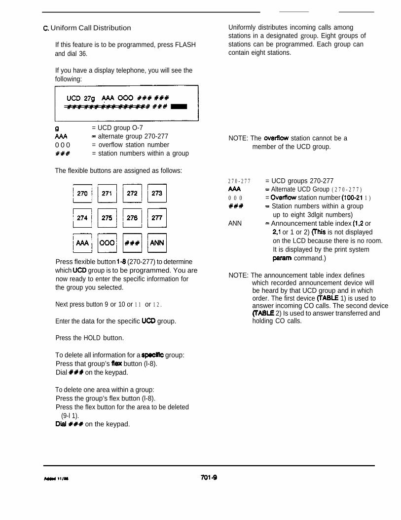
Uniform Call Distribution
If this feature is to be programmed, press FLASHand dial 36.
Uniformly distributes incoming calls amongstations in a designated group. Eight groups ofstations can be programmed. Each group cancontain eight stations.
If you have a display telephone, you will see thefollowing:
= UCD group O-7 alternate group 270-277
0 0 0 = overflow station number= station numbers within a group
The flexible buttons are assigned as follows:
Press flexible button (270-277) to determinewhich group is to be programmed. You arenow ready to enter the specific information forthe group you selected.
Next press button 9 or 10 or 1 1 or 1 2 .
Enter the data for the specific group.
Press the HOLD button.
To delete all information for a group:Press that group’s button (l-8).Dial on the keypad.
To delete one area within a group:Press the group’s flex button (l-8).Press the flex button for the area to be deleted
(9-l 1). on the keypad.
NOTE: The station cannot be amember of the UCD group.
2 7 0 - 2 7 7
0 0 0
ANN
= UCD groups 270-277 Alternate UCD Group ( 2 7 0 - 2 7 7 )
= station number 1 ) Station numbers within a group
up to eight 3dlgit numbers) Announcement table index or
or 1 or 2) is not displayedon the LCD because there is no room.It is displayed by the print system
command.)
NOTE: The announcement table index defineswhich recorded announcement device willbe heard by that UCD group and in whichorder. The first device 1) is used toanswer incoming CO calls. The second device
2) Is used to answer transferred andholding CO calls.

Announcement Table
Press FLASH and dial 39.
If you have a display telephone, you will see thefollowing:
Table 1 represents the first recordedannouncement device.
1 . Enter 1 to specify table
2. TYPE Enter 1 or 2:1 CO line port2 = SLT port
3. Enter the CO port number (2 digits) or SLTextension number (3 digits).
4. TIME Enter message duration seconds).
Press HOLD*. Display will now update.
Enter 2 if you wish to add a secondannouncement device. Repeat the aboveinstructions.
To delete entries currently programmed in atable, press 1 (or and HOLD.
Flex button 12 used to toggle back and forthbetween Tables 1 and 2 to display the valuescurrently programmed, If any.
Recorded announcement(s) may be provided inUCD groups to incoming callers.
1. A maximum of two recorded announcementdevices may be assigned to the groups.
2. The announcement device must beconnected to either a CO line port or a SLTport.
3. Specifies the port number (CO) or extensionnumber the device is hooked up to.
4. The value entered depends on theduration of the actual message you record onthe announcement device. Some devices haveautomatic disconnect at the end of themessage; in this situation the value you entermust be greater than or equal to the actuallength of the message.
*Note: The entire dailing sequence (l-4) must becompleted before depressing HOLD.
701-10

Automatic Timer Determines the amount of time elapsed beforeIf this timer is to be changed, press FLASH button ringing back the redial initiator, reseizing theand dial 38. previously used CO line, and redialing the
If you have a display phone, you will see thisdisplay:
Enter 3 digits on the numeric keypad. Default is seconds. The timer is variable from seconds.
Press HOLD button. (Display will now update)
F. Day/Night COS
Press and dial 40.
stations to have a different COS at nightthan during the day.
Enter a number for station range beingprogrammed. If only one station, enter thatnumber twice (i.e. 101101).
Press PAGE B SELECT button.
This will bring up additional station features to beprogrammed, Including class of service (COS).
The display of current programming for thesefeatures will appear as follows:
BBBB CCC DDDDDDDD
COS
button 2
Dial the 2digit COS entry as follows:1 st digit is day COS
digit is night COS
Depress HOLD. Display now update.
Each station must be assigned a of servicewhich governs that station’s toll restriction.
1 unrestricted2 34
maximum6 intercom
Default gives all stations COS 1 in day mode andCOS 1 in night mode.
701-l 1
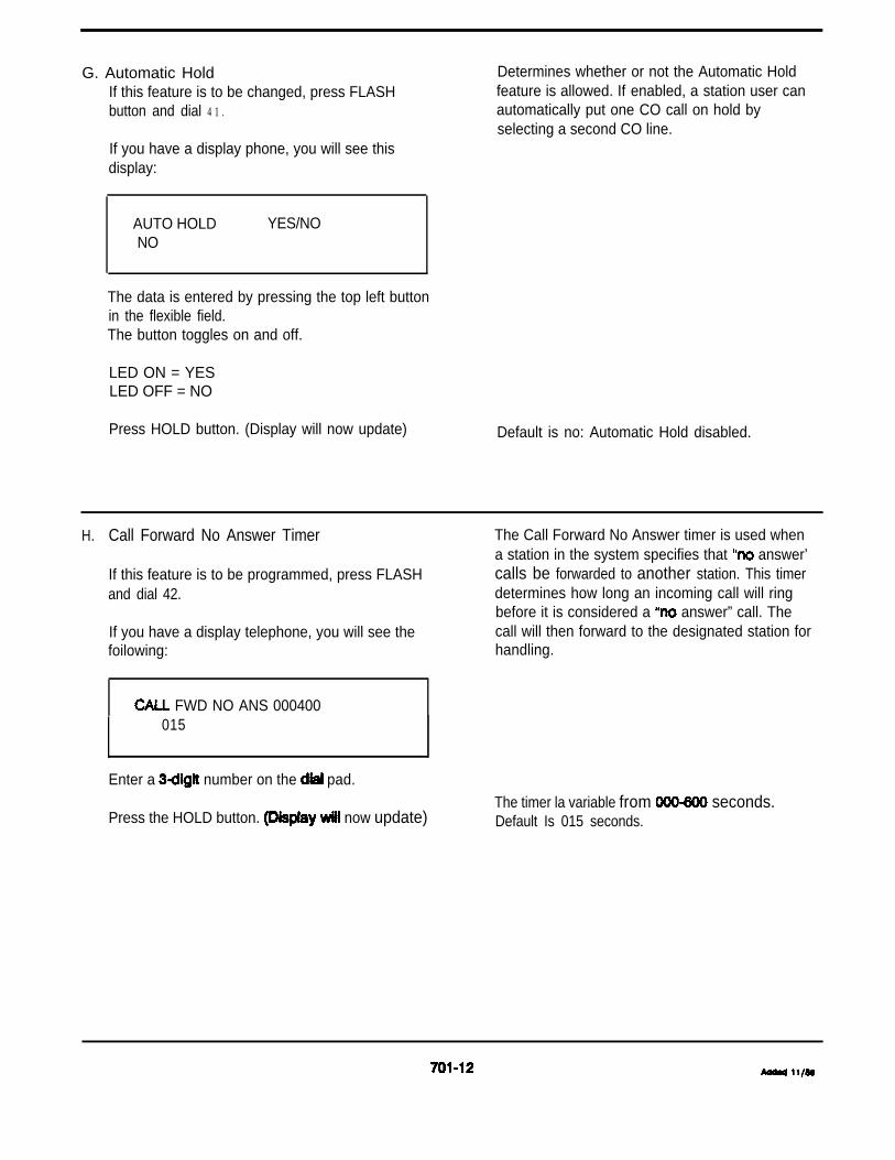
G. Automatic HoldIf this feature is to be changed, press FLASHbutton and dial 4 1 .
Determines whether or not the Automatic Holdfeature is allowed. If enabled, a station user canautomatically put one CO call on hold byselecting a second CO line.
If you have a display phone, you will see thisdisplay:
AUTO HOLD YES/NONO
The data is entered by pressing the top left buttonin the flexible field.The button toggles on and off.
LED ON = YESLED OFF = NO
Press HOLD button. (Display will now update) Default is no: Automatic Hold disabled.
H. Call Forward No Answer Timer
If this feature is to be programmed, press FLASHand dial 42.
If you have a display telephone, you will see thefoilowing:
FWD NO ANS 000400015
Enter a number on the pad.
Press the HOLD button. now update)
The Call Forward No Answer timer is used whena station in the system specifies that answer’calls be forwarded to another station. This timerdetermines how long an incoming call will ringbefore it is considered a answer” call. Thecall will then forward to the designated station forhandling.
The timer la variable from seconds.Default Is 015 seconds.

Voice Mail
Press FLASH and dial 43.
If you have a display telephone, you will see thefollowing display:
= voice mail group (O-7) alternate group (240-247)
P = “put” mail index into voicemail dialing tabie for leaving message
= “get” mail index into voicemail dialing table for retreiving message
voice mail station numbers (upto max.)
l See note
The flexible buttons are assigned as follows:
1. Press flexible button l-8 to determinewhich VM group is to be programmed. You arenow ready to enter the specific forthe group you selected.
3. Enter the data for the group.4. Press the HOLD button.
To delete for a group:Press that flex button (l-8).
on the keypad.
A voice mail system must be provided in order forthis feature to be available. Voice mailautomatically handles unanswered calls. Stationusers can then retrieve messages left for them.Up to eight voice mail groups can be configuredin the system. Each group can contain up to eightvoice mail stations.
VM groups 240-247= alternate group (240-247)
P “Put” mail dialing index(O-7) digits
G mail dialing index(O-7)
station numbers within a group(up to eight numbers)
be an SLT.
*Note: Entries in the “Put” and “Get” of the VoiceMail Group table are required to allow callsto be routed to station extensions assignedIn the group.
See 44 for programming indexes.
To delete one area within a group:Press the group’s button (l-8).Press the flex button for the area to be deleted
Dial on the keypad.
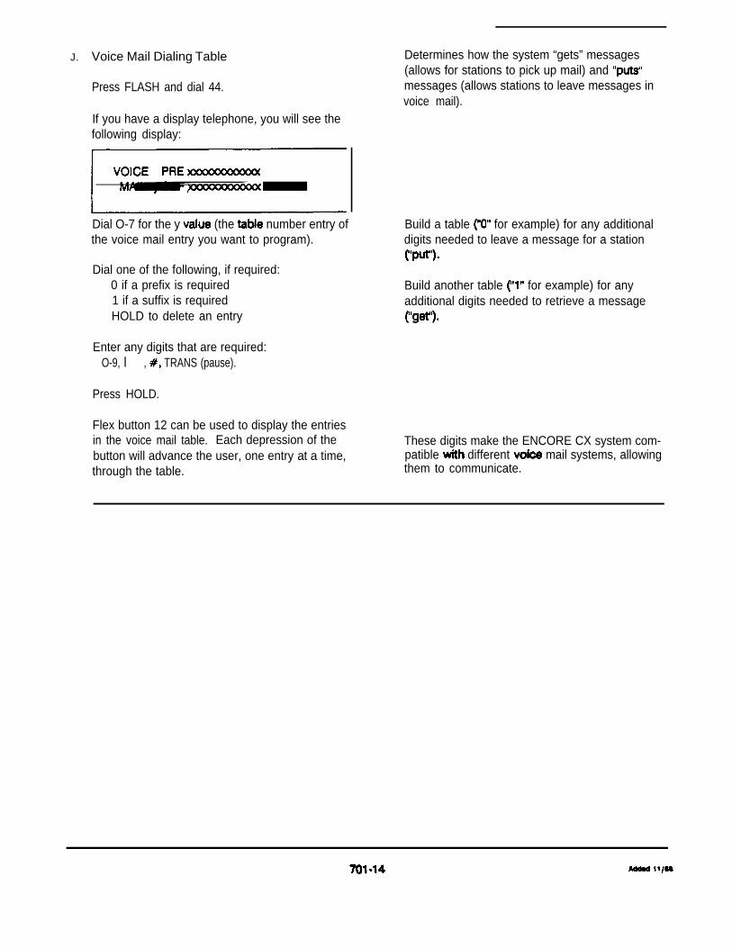
J. Voice Mail Dialing Table
Press FLASH and dial 44.
If you have a display telephone, you will see thefollowing display:
Dial O-7 for the y (the number entry ofthe voice mail entry you want to program).
Dial one of the following, if required:0 if a prefix is required1 if a suffix is requiredHOLD to delete an entry
Enter any digits that are required:O-9, l , TRANS (pause).
Press HOLD.
Flex button 12 can be used to display the entriesin the voice mail table. Each depression of thebutton will advance the user, one entry at a time,through the table.
Determines how the system “gets” messages(allows for stations to pick up mail) and messages (allows stations to leave messages invoice mail).
Build a table for example) for any additionaldigits needed to leave a message for a station
Build another table for example) for anyadditional digits needed to retrieve a message
These digits make the ENCORE CX system com-patible different mail systems, allowingthem to communicate.

K. Least Cost Routing (LCR) Priority
1. ROUTE LIST TABLE
Press FLASH and dial 5 1 .
Press program button 4.
If you have a display tdephone, you will see thefollowing display:
RR Route Number (W-15)T Time Period Route List (14)G CO Line Group (l-7)DD = Insert/Delete Table (W-19)L = number (l-7)
1 is highest 7 is lowest priority
Press HOLD button. Display will now update.
2. STATION PROGRAMMING
Press and dial 40.
Enter a 6digit number for station range beingprogrammed. If only one station, enter thatnumber twice (i.e. 101101).
Press HOLD button.
If you have a display telephone, you see thefollowing:
XXX-XXX A PAGE DND SPDQUE PLA LCR
Press program 9.
Enter LCR (l-7)1 highest 7 lowest
Press HOLD button. Display now update.
Allows route entry priorities to be assigned on aper station basis. This allows or disallowsspecific stations the ability to access certaintrunk groups through LCR.
To enter additional CO line groups in the sametime for the same route number, G DD L HOLD.
To enter data for a different list within a route,press program button 4 and enter all data (RR TG DD Repeat the above to program a newRoute Number (00-l 5).
A station is able to use a trunk group thestation’s number is equal to or greaterthan the trunk group’s number.
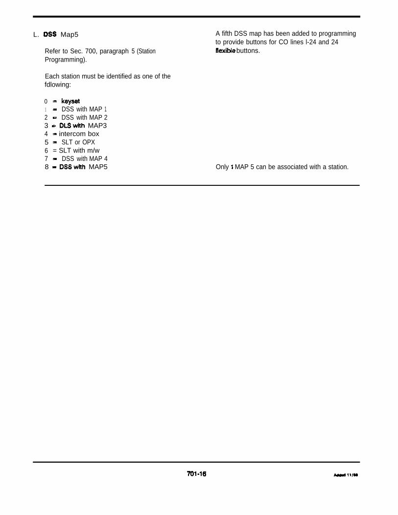
L. Map5
Refer to Sec. 700, paragraph 5 (StationProgramming).
A fifth DSS map has been added to programmingto provide buttons for CO lines l-24 and 24
buttons.
Each station must be identified as one of thefdlowing:
01 DSS with MAP 12 DSS with MAP 23 MAP34 intercom box5 SLT or OPX6 = SLT with m/w7 DSS with MAP 48 MAP5 Only MAP 5 can be associated with a station.

5. REMOTE PROGRAMMING 5 . 1 ENTERING THE PROGRAMMING MODE
Complete programming can be done remotely from aterminal. This allows changes to the system data basefor feature allocation and configuration. Changes canbe made, via the terminal, while the system is beingused. The terminal is a data device connected tothe port on system CPU PCB.
Certain buttons on the terminal compare to thebuttons on the telephone keypad that are normallyused to program the system
a.b.
e.
Press Enter key on the terminal.Enter the password when prompted:
The terminal will prompt ADM.Proceed to program as you normallywould from a on-site.After completing programming, enter and therpress the ENTER key.
NOTE: Data is displayed after the program code isentered or after the return key is pressed.
Pressing the buttons on the terminal thatcorrespond to the flex buttons is the same aspressing the flex buttons on station Forexample, a feature is then pressing theterminal key and enter that feature.
In place of button toggling to enable/disablea feature, press the key on the data terminal todisable a feature. Use the key on the dataterminal to enable a feature. After pressing the + or key on the terminal, press the appropriatekey that corresponds to the equivalent flex button.This operation can be used when the currentstatus of a feature is unknown; if a computer isused to load the system data base into the system,the current status of the feature will be unknownand use of the + and option in required.

6. FEATURE PACKAGE VI FEATURES
A. Data Base Update (Flash 80)
The routine previously necessary to invokechanges of the customer data base (Flash 80)into permanent memory is no longer required.All changes made in the administrationprogramming procedures for the customerdata base are invoked when the HOLD buttonis pressed.
B. Station Programming (Flash 40)
Two changes have been made in the StationAttributes Programming routine.
Disable SLT Add-On Conference
If programming for this new feature is desired,press FLASH and dial 40.
If you have a display telephone, you will seethe following:
STATION ATTRIBUTESSELECT A STA RANGE I
Enter a number for a station(s) beingprogrammed. (If only 1 station is beingprogrammed, enter that number twice.)
Toggle ON program button 6 to deny the SLTAdd-On Conference feature.
Press HOLD button. (Display now update)
2. CO l
the entry for buttonassignments from to 4 digits. Now the buttonassignments are made in the following format:
If the Station Type has been assigned as 4 or5, Button 8 of Page A controls the SLT Add-OnConference feature. The restriction of this fea-ture can be used for SLT ports assigned forAutomated Attendant interface. SomeAutomated Attendants fail to properly detectwhen a station user has answered a super-vised transfer attempt, thus causing an unex-pected Add-On Conference if the AutomatedAttendant attempts to recover the call to betransferred.
The programming routine continues to provideOHVA selection for when Station Type is used.
By default all station are allowed the SLT On Conference feature.
CO ringing for button assignment is no selected using page button 8. See the newfeature “CO Line Ringing Assignment’ definedbelow.
701-18

BBLLBB flexible button number (01-24)LL line assigned to that button (01-36)
Note: Programming of CO line at a 2500 type set isno longer required using this routine. See thenew feature “CO line Ringing Assignment”defined below.
If a button is not to be assigned as an outsideline, the entry should be BB number.
To program a button for use as a LOOP but-ton, enter BBOO.
C. CO Llne Ringing
Each CO line in the system may be assignedinitial incoming ringing to one of the followingdestinations:
one or more stations or to a UCD, Voice Mail or Hunt GroupOff-Net (System Speed)
1. Entering the programming mode.2. Press FLASH and dial 30.3. If you have a display telephone, you will see
the following:
CO LINE ATTRIBUTESSELECT A CO LINE RANGE I
From the dial pad, enter the CO linerange to be programmed The displaywill show:
CO XX-XX A DT CO UNA .FL20
Press the PAGE B button (Button 9) to toggleto the PAGE B diiay. The diiay will showthe information:
CO XX-XX B RING I
BUT-TON ATTRIBUTE
Incoming calls directed Off-Net will be con-nected to an outgoing system speed bin. Sta-tions that are assigned for initial ring-in canuse a LOOP button(s) to answer the call(s).
CO lines assigned to ring multiple stations willnot follow any stations’ forward to a UCD,Voice Mail, Hunt Group or Off-Net. Forwardingto another station will be allowed.
Multiple station assignments are allowed for aparticular CO line in a mixture of Day, Night, orDay Night ring types. An incoming CO linemay be programmed to any number of stationsbut it cannot be programmed to a mixtureof stations and groups (ie. a Hunt Group and 4stations, or more than one Hunt Group).
1 CO Ringing Assignments2 Display CO Ringing Assignments
Cont
701-19

Press Button 1 to program ring assignments.The following information will be shown:
Enter the three digit destination (DDD) and thesingle digit ring type (R) followed by the HOLDbutton.
Press Button 2 to display assignments. As-signments will be displayed in sets of 8 up tothe number programmed. Press button 2 addi-tional times to cycle to the next group of 8 assignments.
The following LCD format will be used to dis-play the assignments.
DDDR DDDR DDDR DDDRDDDR DDDR DDDR DDDR
DDD Destination D for Day, N for Night or B for Both Day &
Night.
Valid 3 destinations are:020-099 Svstem Bins 20-99100-211 240-247 Voice Mail Groups l-8260-267 Hunt Groups l-8270-277 UCD Groups l-8
Valid are:0 Unassigned1 Day Ringing2 Night Ringing3 Day Night Ringing
Multiple station assignments are accomplishedby assigning another destination with status, DDDR, and pressing the HOLD button.This can be done for up to the maximum num-ber of stations on the system.
Tone
1. Enter the programming mode.2. Press FLASH and dial 45.3. If you have a display telephone, you will see
the following display:
KEY ANNOUNCE TONES 3 I
4. Dial the desired number:
5. Press HOLD.
701-20

E. Least Cost Routing Toll Calls
1. Enter the programming mode.2. Press FLASH and dial 51.3. Press button 8 of the programming buttons.4. If you have a display telephone, you will see
the following display:
5. the desired route number.6. Press HOLD.
F. UCD New Call
1. Enter the programming mode.2. Press FLASH and dial 37.3. Press button 4 of the programming buttons.4. Enter on the dial pad (000-999 sec.)
Press HOLD.
701-21

,ADDENDUM 1, FEBRUARY
LEAST COST ROUTING (LCR)
TABLE OF CONTENTS
DESCRIPTION
1.
2.
3.
4.
5.
6.
7.
8.
9.
10.
11.
12.
13.
INTRODUCTION . . . . . . . . . . . . . . . . . . . . . . . . . . . . . . . . . . . . . . . . . . . . . . . . .
PROCESSOR BOARD (2994402) ANDLCR (2996301). . . . . . . . . . . . . . . . . . . . . . . . . . . . . . . . . . . . . . . .
FEATURES & CHARACTERISTICS . . . . . . . . . . . . . . . . . . . . . . . . . . . . . . . . . .
ROUTE LIST TABLE . . . . . . . . . . . . . . . . . . . . . . . . . . . . . . . . . . . . . . . . . . . . . .
TIME OF DAY ROUTING . . . . . . . . . . . . . . . . . . . . . . . . . . . . . . . . . . . . . . . . . . 1
INSERT/ DELETE TABLES . . . . . . . . . . . . . . . . . . . . . . . . . . . . . . . . . . . . . . . . . 2
EXCEPTION TABLE . . . . . . . . . . . . . . . . . . . . . . . . . . . . . . . . . . . . . . . . . . . . . . . 2
TABLE. . . . . . . . . . . . . . . . . . . . . . . . . . . . . . . . . . . . . . . . . . . . . . . . . . . 2
TABLE (OFFICE CODES) . . . . . . . . . . . . . . . . . . . . . . . . . . . . . . . . . . 3
OPERATION . . . . . . . . . . . . . . . . . . . . . . . . . . . . . . . . . . . . . . . . . . . . . . . . . . . . . 3
COMPLETING . . . . . . . . . . . . . . . . . . . . . . . . . . . . . . . . . . . . 4
LCR PROGRAMMING . . . . . . . . . . . . . . . . . . . . . . . . . . . . . . . . . . . . . . . . . . . . 412.1 EXCEPTION CODE TABLE . . . . . . . . . . . . . . . . . . . . . . . . . . . . . . . . . . . . 412.2 DAILY TIME TABLE . . . . . . . . . . . . . . . . . . . . . . . . . . . . . . . . . . . . 512.3 WEEKLY SCHEDULE TABLE . . . . . . . . . . . . . . . . . . . . . . . . . . . . . . . . . . 512.4 . . . . . . . . . . . . . . . . . . . . . . . . . . . . . . . . . . . . . . . . . . 512.5 INSERT/DELETE TABLE . . . . . . . . . . . . . . . . . . . . . . . . . . . . . . . . . . . . . . 512.6 TABLE . . . . . . . . . . . . . . . . . . . . . . . . . . . . . . . . . . . . . . . . . . . . . 612.7 . . . . . . . . . . . . . . . . . . . . . . . . . . . . . . . . . . . . . . . . . . . . . 6
ENABLE . . . . . . . . . . . . . . . . . . . . . . . . . . . . . . . . . . . . . . . . . . . . . . . . . . . . 6
701 A-A
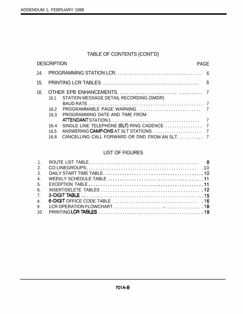
ADDENDUM 1, FEBRUARY 1988
DESCRIPTION
TABLE OF CONTENTS (CONT’D)
PAGE
14.
15.
16.
1.2.3.4.5.6.7.a.9.10.
PROGRAMMING STATION LCR. . . . . . . . . . . . . . . . . . . . . . . . . . . . . . . . . . . . 6
PRINTING LCR TABLES . . . . . . . . . . . . . . . . . . . . . . . . . . . . . . . . . . . . . . . . . . 6
OTHER EPB ENHANCEMENTS. . . . . . . . . . . . . . . . . . . . . . . . . . . . . . . . . . . 716.1
16.216.3
16.416.516.6
STATION MESSAGE DETAIL RECORDING (SMDR)BAUD RATE . . . . . . . . . . . . . . . . . . . . . . . . . . . . . . . . . . . . . . . . . . . . . . . . 7PROGRAMMABLE PAGE WARNING. . . . . . . . . . . . . . . . . . . . . . . . . . . . 7PROGRAMMING DATE AND TIME FROM
STATION 1 . . . . . . . . . . . . . . . . . . . . . . . . . . . . . . . . . . . . . . 7SINGLE LINE TELEPHONE RING CADENCE . . . . . . . . . . . . . . . . 7ANSWERING AT SLT STATIONS . . . . . . . . . . . . . . . . . . . . . 7CANCELLING CALL FORWARD OR DND FROM AN SLT. . . . . . . . , , . 7
LIST OF FIGURES
ROUTE LIST TABLE. . . . . . . . . . . . . . . . . . . . . . . . . . . . . . . . . . . . . . . . . . . . . . . .CO LINEGROUPS . . . . . . . . . . . . . . . . . . . . . . . . . . . . . . . . . . . . . . . . . . . . . . . . .10DAILY START TIME TABLE.WEEKLY SCHEDULE TABLEEXCEPTION TABLEINSERT/DELETE TABLES . . . . . . . . . . . . . . . . . . . . . . . . . . . . . . . . . . . . . . . . . . .
. . . . . . . . . . . . . . . . . . . . . . . . . . . . . . . . . . . . . . . . . . . . . . . OFFICE CODE TABLE . . . . . . . . . . . . . . . . . . . . . . . . . . . . . . . . . . . . .
LCR OPERATION FLOWCHART. . . . . . . . . . . . . . . . . . . . . . . . . . . . . . . . . . . .PRINTING . . . . . . . . . . . . . . . . . . . . . . . . . . . . . . . . . . . . . . . . . . .
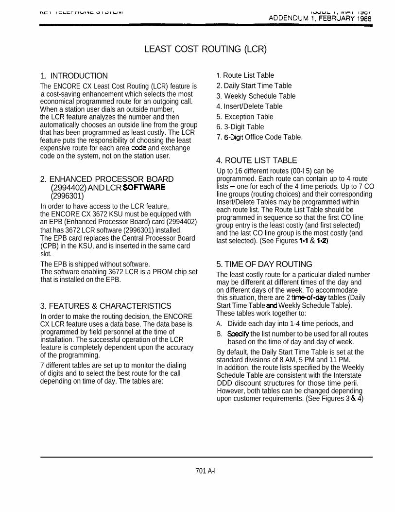
LEAST COST ROUTING (LCR)
1. INTRODUCTIONThe ENCORE CX Least Cost Routing (LCR) feature isa cost-saving enhancement which selects the mosteconomical programmed route for an outgoing call.When a station user dials an outside number,the LCR feature analyzes the number and thenautomatically chooses an outside line from the groupthat has been programmed as least costly. The LCRfeature puts the responsibility of choosing the leastexpensive route for each area and exchangecode on the system, not on the station user.
2. ENHANCED PROCESSOR BOARD(2994402) AND LCR (2996301)
In order to have access to the LCR feature,the ENCORE CX 3672 KSU must be equipped withan EPB (Enhanced Processor Board) card (2994402)that has 3672 LCR software (2996301) installed.The EPB card replaces the Central Processor Board(CPB) in the KSU, and is inserted in the same cardslot.The EPB is shipped without software.The software enabling 3672 LCR is a PROM chip setthat is installed on the EPB.
3. FEATURES & CHARACTERISTICSIn order to make the routing decision, the ENCORECX LCR feature uses a data base. The data base isprogrammed by field personnel at the time ofinstallation. The successful operation of the LCRfeature is completely dependent upon the accuracyof the programming.7 different tables are set up to monitor the dialingof digits and to select the best route for the calldepending on time of day. The tables are:
Route List Table2. Daily Start Time Table3. Weekly Schedule Table4. Insert/Delete Table5. Exception Table6. 3-Digit Table7. Office Code Table.
4. ROUTE LIST TABLEUp to 16 different routes (00-l 5) can beprogrammed. Each route can contain up to 4 routelists one for each of the 4 time periods. Up to 7 COline groups (routing choices) and their correspondingInsert/Delete Tables may be programmed withineach route list. The Route List Table should beprogrammed in sequence so that the first CO linegroup entry is the least costly (and first selected)and the last CO line group is the most costly (andlast selected). (See Figures &
5. TIME OF DAY ROUTINGThe least costly route for a particular dialed numbermay be different at different times of the day andon different days of the week. To accommodatethis situation, there are 2 tables (DailyStart Time Table Weekly Schedule Table).These tables work together to:A. Divide each day into 1-4 time periods, andB. the list number to be used for all routes
based on the time of day and day of week.By default, the Daily Start Time Table is set at thestandard divisions of 8 AM, 5 PM and 11 PM.In addition, the route lists specified by the WeeklySchedule Table are consistent with the InterstateDDD discount structures for those time perii.However, both tables can be changed dependingupon customer requirements. (See Figures 3 4)
701 A-l

--.ISSUE 1 , MAY 1987ADDENDUM FEBRUARY 1988
6. INSERT/DELETE TABLESThere are 20 Insert/Delete Tables (00-l 9). Up totwenty digits, including pauses, can be inserted andup to sixteen digits deleted. Digits can be insertedbefore or after the number dialed, but can be deletedonly from the beginning of a number dialed.For instance, if a user dials a long distance call thatshould be placed on a home area code foreignexchange line, the digit dialed by the usermust be deleted before the call is placed on that FXline. An Insert/Delete Table can be programmed to dothis. Digits can also be added to a number that hasbeen dialed by the user. access codes, forinstance, can be automatically inserted by thesystem. Figures to
7. EXCEPTION TABLEThis table is used to route operator assisted callsand any other calls which would use a or2-digit number rather than a area code.There are 20 available entries in this table.Each entry contains both the exception code (1 or 2digits) and the two-digit route number (00-l 5) to beused for that code. Figure 5) There are nodefault data entries in the Exception Table.CAUTION: The Dialing Privileges tables are not
checked for any calls routed via theException Table.
8. TABLEThis table is divided into 2 sections: “Leading
is dialed before the number) and Leading (no is dialed before the number). This gives
the system the ability to handle call routing in areasthat require a before a long distance number,as well as in areas that do not require the
This table provides routing based on the first threedigits of the number dialed including: area codes:service codes such as 911,411, etc.; office codesfor the home NPA and direct International dialaccess (IDDD). It should also include, for each digit code, the route to be used, the number of digitslikely to be dialed and if the Table is to bechecked. This table can include 1000 entries from
(Bee Figure CAUTION: All local office codes must be
included in this table or local callscannot be completed through LCR.
The number of digits likely to be dialed controlsrouting of calls as follows:A. Fewer than the programmed number of digits
dialed:The system pauses 5 seconds after the last digit isdialed before routing.B. Exactly the programmed number of digits dialed:The system routes the call as soon as it sees thelast digit it is programmed to expect.C. More than the programmed number of digits
dialed: routes the call as soon as it sees the last
digit it is programmed to expect, and ignores alldigits in excess of the programmed number.NOTE: A minimum of 3 digits is required for route
selection by the Table.Once the system has routed the call and sent alldigits, the keypad is live and additional digits can bedialed if required.A default has been established for area codes,and for both the “Leading and “Non Leading sections of the Table for service codes andoffice codes associated with the home NPAPlease refer to the default data base fordetailed information. Exhibit I for the DefaultData Base.
701 A-2

I , ADDENDUM FEBRUARY 1988
9. TABLE (Office Codes)
The Table must be referenced by an areacode in the Table. It is usd to determinethe route for individual office codes when precededby that specific area code. The 6-Digit Table caninclude 20 office code maps. Each map can
route up to 800 office codes to oneof the 15 possible route lists. Each map must beassociated with a specific area code in the Table. Several different office code maps can beused with the same area code to provide additionalrouting flexibility. There are no default entries in anyof the 20 different office code maps.(Sea Figure 8)If the office code dialed is not found in the 6-Digit
Code Table, the call is then routed accordingto the route programmed in the Table.
10. OPERATIONTo access the LCR feature:a. Lift the handset.b. Dial 9. Hear dial tone.c. Dial if required.d. Dial area code, if required.The system first checks to see if the number dialedis more than 2 digits. If it is 2 digits or less, the callis processed according to instructions in theException Table. If the number is not found in theException Table, the call is denied.If the number is more than 2 digits it then goes to the3-Digit Table where the first 3 digits are checked,whether office cods or area to see if thosedigits are found there. If not found, the call is denied.If the digits are found in the Table, the systemthen checks this table to see if the Tablemust be referenced.If the 6digit column is marked “yes”, the systemchecks to see if the office code of the number dialedis found in this table.
If the office code is found in the Table,the number is then checked against DialingPrivileges. When LCR is enabled, Dialing Privilegesare determined only by station Class of Service.
line Class of Service is no longer applicable.All CC lines are considered Class of Service 1.If the call is not allowed through Dialing Privileges,the call is denied. If it is allowed, the call goes tothe Route List Table to be sent by the route indicatedin the Table.After a call is sent to the Route List Table, it can nolonger be denied: a station cannot be programmed todial on some CC line groups in a route but not onother groups in the same route.If the office code is not found in the Table,the call is referred back to the Table. The callis checked against Dialing Privileges. If the number isdenied there, the call is denied. If it is allowed, thecall then goes back to the Route List Table to besent by the route indicated in the Table.If a line is not available in the first CC line group in alist, the system advances to the next choice in thelist and searches for a free line. The processcontinues until an available line is found or thelast available line group is searched.If no lines are available in any of the CC line groupsprogrammed for that list in the route, the call can bequeued on to the first choice (least costly) line group.If the user waits 3 seconds after dialing the number,he/she will hear confirmation tone, which indicatesthat he/she is queued on to the first choice linegroup.The user must hang up after hearing confirmationtone to be placed in queue. Queuing is on a FIFO(First In/First Out) basis. There is no Queue Priority.The queue can be canceled by dialing the digit “4”.The queue will be canceled automatically after thesystem tries three times unsuccessfully to call back abusy The queue will also cancel automaticallyafter queue callback is unanswered for fifteen (15)seconds. To answer a queue callback, press theline or pool key flashing at the queue callback rate(480 ipm flutter). call will be dialed automatically.
701 A-3

ADDENDUM 1 , FEBRUARY 1988
10.1 CO LINE GROUP ACCESSRestrictions in a system with LCR apply only whena station attempts to access a line in a groupthrough a direct key appearance of that line or bydialing the Trunk Group Access Code. A station is notrestricted from access to a line group if that groupis part of a route which is accessed by the stationvia the LCR feature access code (dial This istrue regardless of whether or not LCR access isforced in the system.See Figure 9 for an LCR operation flow chart.
11. COMPLETING WORKSHEETSIt is extremely important that the worksheets becompleted before programming the LCR tables.It is suggested that the worksheets be completed inthe following order. First fill out the CO line grouptable, then the Exception Table (as this is the firsttable the system will check when a number is dialed).Then determine time of day routing by completingboth the Daily Start Time Table and the Weekly
Table. These times are used in the Route Table. Next determine time and CO line group
priority for the various routes to be used.Then complete the Insert/Delete Table and, usingtable, complete the last column in the Route ListTable.When the Route List Table has bean completed,then fill out the Table. Area codes can broken into specific office codes by using the Digit Table. Refer to Figure for a flow chart onthe operation of LCR.
12. LCR PROGRAMMING
this
If you are in the program mode, continua using theProgram Codes. If you are starting to program atthis point, enter the program first (Sac. 700,2.1).To initialize all LCR Tables to default data, FLASH To program the for least routing, FLASH 51.
NOTE: We suggest that LCR disabled duringprogramming. LCR programming does require FLASH 80 for update.
You will see the following display if you have adisplay telephone:
LCR TABLESSELECT A TABLE
There are 7 tables which can be programmed forLCR. Use the program buttons as follows to programthese tables:
Press the button for the table being programmed.NOTE: The only w a y to data in the LCR Tables
12.1
If you
is to do-a of the Table(s) inquestion. See Figure 10 for details on how toobtain printouts.
EXCEPTION CODE TABLE(Program Button 3)
have a display phone, you will see the followingdisplay:
EXCEPTION CODE TABLEENTER S XX RR HOLD
to add to table
XX exception codes(for single as 2nd digit)
RR route number, 00-l 5HOLD must be pressed after each entry. The displaywill now update.Press program button 3 again for further entries.Up to 20 Exception may be programmed inthis table.

ENCORE CX 816 SECTION 800KEY TELEPHONE SYSTEM ISSUE MAY 1987
ENCORE CX 818 SYSTEM CHECKOUT PROCEDURES
TABLE OF CONTENTS
DESCRIPTION PAGE1. INTRODUCTION . . . . . . . . . . . . . . . . . . . . . . . . . . . . . . . . . . . . . . . . . . . . . . . . . . . . . . . . . . . . ,
PRELIMINARY PROCEDURES . . . . . . . . . . . . . . . . . . . . . . . . . . . . . . . . . . . . . . . . . . . . . . . ,
3. OPERATIONAL TESTS . . . . . . . . . . . . . . . . . . . . . . . . . . . . . . . . . . . . . . . . . . . . . . . . . . . . . .
LIST OF FIGURES
1. ENCORE CX KEY TELEPHONE . . . . . . . . . . . . . . . . . . . . . . . . . . . . . . . . . . . . ,
800-A

ENCORE CX 8 16 SECTION 800KEY TELEPHONE SYSTEM ISSUE MAY 1987
ENCORE CX 816 SYSTEM CHECKOUT PROCEDURES
1. INTRODUCTIONThis section describes the procedures that shouldbe followed during system start-up and is intendedto be used by a technician trained in the installationand maintenance of the ENCORE CX 816 KeyTelephone System. The installer will also find thesetests to be helpful in the event of system malfunctionand troubleshooting.
A.
B.
C.
D.
2. PRELIMINARY PROCEDURESBefore starting the functional test procedures, it isrecommended that the following checklist becompleted:
E.
F.
Ensure that the KSU is properly grounded.
Inspect the MDF for shorted wiring orimproper polarity.
Make sure the plug-ended MDF cablesconnected to the KSU are plugged into thecorrect position.
Make sure the Program Module is firmly seatedin its socket. (816 only)
Check music source connections and alarmconnections if provided.
Plug the AC power cord into the dedicated1 17 VAC outlet.
FIGURE 1. ENCORE CX KEY TELEPHONE
800-l

SECTION 800 ENCORE CX 816 SYSTEM CHECKOUT PROCEDURESISSUE MAY 1987
3. OPERATIONAL TESTS
OPERATIONAL TEST RESULT FUNCTION
1. Depress MON button. 1.1 MON button lights steady. 1 Normal
1.2 ICM dial tone heard. 1.2 Normal
1.3 No reaction. 1.3 Check station wiring,modular cord.
2. Intercom Call 2.1 MON button lights steady. 2.1 Normal(Handsfree
2.2 3 tones heard at called 2.2 NormalDial desired station. and calling station.
2.3 Handsfree communication 2.3 Normalpossible if station is inHF mode.
2.4 Handsfree communication 2.4 Check stationnot possible if station is programming for in PV or TN mode. set option and that the
station is in HF mode.
3. ICM Call(Tone ringing)Dial desired station.
3.1 tone heard by 3.1calling station.
3.2 Ringing heard at called 3.2 Normalstation.
3.3 HOLD button flashes at 3 .3 Normalcalled station.
3.4 Calling station must lift 3 .4 Normalhandset to converse.
4. ICM Call(Privacy mode)
desired station.
4.1 3 tones heard at called 4.1station.
4.2 Station can hear voice 4.2 Normalannouncement.
4.3 Called station cannot 4.3talk back.
800-2

ENCORE CX 816 SYSTEM CHECKOUT PROCEDURES SECTION 800ISSUE MAY 1987
3. OPERATIONAL TESTS
OPERATIONAL TEST RESULT FUNCTION
5. Outgoing CO calls. 5.1 CO line LED lit steady. 5.1 NormalPress CO line button.
6. incoming Calls.
5.2 Dial tone heard. 5.2 Norma)
5.3 No LED indication. 5.3 Check station programming
5.4 No dial tone. 5.4 Check CO connections.
6.1 CO ringing heard. 6.1 Normal
6.2 CO line LED flashing at 6.2 Normal30 IPM.
6.3 No ringing heard. 6.3 Check programming.
6.4 No LED flashing. 6.4 Check CO line‘connections.
7. Press flashing CO linebutton.
7.1 CO line LED lit steady. 7.1 Normal
8. Conference.(Multi-line)Make CO line call.Press CONF button.
8.1 Both parties hear Conf. 8.1 Normaltone.
8.2 tine goes on hold. 8 . 2
Make another CO call.Press CONFbutton twice.
8.3 CONF LED flashes. 8.3 Normal
Conference initiator 8.4 Two outside lines remain 8 . 4 Presses CONF button land hangs up.’Conference initiator 8.5 CONF LED lit steady. 8.5 Normallifts handset and pressesCONF button. 8.0 Conf. tone heard. 8 . 0
8.7 Initiator re-enters 8.7 Normalconference.
9. Internal Conference.Make an intercom call.Press CONF button. 9.1 Party goes on Hold. 9.1Make another intercomcall.Press CONF twice. 9.2 3 parties are connected. 9.2 Normal
‘Unsupervised conference is an option on the 3672 only: not available on 816.
800-3

SECTION 800 ENCORE CX 816 SYSTEM CHECKOUT PROCEDURESISSUE MAY 1987
3. OPERATIONAL TESTS (CONT’D)
OPERATIONAL TEST RESULT FUNCTION
10. Add On Conference.Make a CO call.Press CONF button. 10.1 CO line goes on hold. 10.1 NormalMake an intercom call. 2 Station signals according 10.2 Normal
to intercom switch.
Press CONF button twice. 10.3 All 3 parties are connected. 10.3 Normal
11. Background Music. 11.1 MON button flashes 11.1 NormalWith station idle, momentarily.dial code “73”.
11.2 Music is heard through 11.2 Normalspeaker (if programmedand music source isconnected). l
11.3 No music is heard. 11.3 Check speaker volumeon phone.Check music sourceconnections.
Dii “73” again.
12. Ring Volume.With station in TNmode, have anotherstation intercom callyour instrument.
Music is OFF.
12.1 Ring tone is heard.
12.2 No ring is heard or ringingis too loud.
11.4 Normal
12.1 Normal
12.1 Use adjustmentswitch on front ofinstrument to adjust todesired level. Checkstation connections.
13. Speaker Volume.Press MON button.
13.1 ICM tone is heard. 13.1 Normal
13.2 Dial tone is not head 13.2 Adjust volume level withor is too loud. speaker volume slide
switch.
14. DND (Do Not Disturb)Press DND buttonwhile on-hook.
14.1 DND LED lit steady. 14.1 Normal
14.2 LED does not light. 14.2 Verify that station isallowed DND in
programming.
Press DND button again. 14.3 DND light goes out. 14.3 Normal
l A second music source is an option on the 3672 only: not available on 616.
800-4

ENCORE CX 816 SYSTEM CHECKOUT PROCEDURES SECTION 800ISSUE MAY 1987
3. OPERATIONAL TESTS (CONT’D)
OPERATIONAL TEST
Call Transfer.Make a CO call.Press TRANS button.
Receive ICM dial tone.
Dial desired station.
Announce transfer orsimply hang up.
RESULT
15.1 CO line goes on Hold.
15.2 Called station signalsaccording to signal switch.
15.3 Called station receivestransferred ring andCO line flashes at60 IPM.
FUNCTION
15.1 Normal
15.2 Normal
15.3 Normal
800-5

ENCORE CX 3672 SECTION 80 1KEY TELEPHONE SYSTEM ISSUE MAY 1987
ENCORE CX 3672 SYSTEM CHECKOUT PROCEDURES
TABLE OF CONTENTS
DESCRIPTION PAGE1. INTRODUCTION . . . . . . . . . . . . . . . . . . . . . . . . . . . . . . . . . . . . . . . . . . . . . . . . . . . . . . . . . . . . .
2 PRELIMINARY PROCEDURES . . . . . . . . . . . . . . . . . . . . . . . . . . . . . . . . . . . . . . . . . . . . . . . . .
3. POWER UP SEQUENCE. . . . . . . . . . . . . . . . . . . . . . . . . . . . . . . . . . . . . . . . . . . . . . . . . . . . . .
OF FIGURES
1. STATION WITH DSS CONSOLES. . . . . . . . . . . . . . . . . . . . . . . . . . . . . . . . . . . . 12. . . . . . . . . . . . . . . . . . . . . . . . . . . . . . . . . . . . . . . . . . . . . . . . . . . . . . . . . . . 23. CENTRAL PROCESSING BOARD (CPB) . . . . . . . . . . . . . . . . . . . . . . . . . . . . . . . . . . . . . . . . . 2
1. POWER SUPPLY TESTS.. . . . . . . . . . . . . . . . . . . . . . . . . . . . . . . . . . . . . . . . . . . . . . . . . . . . . 3
801 -A

ENCORE CX 3672 SECTION 80 1KEY TELEPHONE SYSTEM ISSUE MAY 1987
ENCORE CX 3672 SYSTEM CHECKOUT PROCEDURES
1. INTRODUCTIONPrior to actual power up and initialization, the keysystem should be checked over to avoid start updelays or improper loading. A step-by-step check listis provided this purpose.
D.
2.A.
B.
C.
E.
PRELIMINARY PROCEDURES
Verify that the DC output power cord from thepower supply is plugged into the DC connectoron the KSU.
F.
Ensure that the KSU is properly groundedaccording to instructions provided inSection
G.
The DC/DC converter must be installed in theKSU and firmly seated in its card connectorposition. The ON/OFF switch should be inthe OFF position. The circuit breaker switchshould be in the ON position.
H.
Verify that all are firmly plugged into theircorrect color coded card slot positions.This can be done by comparing the color of theKTU ejector tabs with the colored labels on theKSU shelves.
Check the Service switches on the associated The switches should be in the
NORMAL position.Inspect the MDF for shorted wiring and improperpolarity that would affect the key telephone orDSS consoles.
All switches on the CPB should be ONso that default data can be loaded into memorywhen the system is powered up. Check theremaining switches to confirm the settings(Sec. Make certain that the lithiumbattery Is connected to the battery (+) terminal.
Make sure that plug-ended MDF cablesconnected to the KSU are secure and areplugged into the correct position.
801-l

SECTION 80 1 ENCORE CX 3672 SYSTEM CHECKOUT PROCEDURESISSUE MAY 1987
3. POWER UP SEQUENCEThe power up sequence involves the properapplication of AC power to the system, monitoringDC/DC converter and observing on theCPB A successful power up is assured if theinstallation check-list has been followed.When system power is applied, default data isloaded into memory.
The 8 white DIP switches on the front of the CPBshould all be in the ON position.
A. Plug the AC power cord of the power supplyinto the dedicated 117 VAC outlet. The LED on the power should light.
B. Turn the power switch on the DC/DC converterON.
C. The 2 red on the DC/DC convertershould light immediately.
INTERNAL WIRING TO
FIGURE 2. DC/DC CONVERTER
D. Press the reset button on the CPB.
The CPB has 8 red located on the front ofthe card. Upon a successful power up,
1 and 2 will flicker and then go off.LED 8 will remain lit.If LED 1 only is lit, this indicates a ROM failure.If LED 1 and 2 only are lit, this means aRAM failure.
F. Check for and + operation on theDC/DC converter and adjust if necessary.A digital read-out meter is required to adjust the5 volts. Turn switch 8 on the CPB off to protectaccidental loading of default data in case ofpower outage.
G. The system is ready for programming.See Section If any problems haveoccurred, see operation tests in section
or Troubleshooting in Section
SWITCHES
FIGURE 3. CPB
801-2
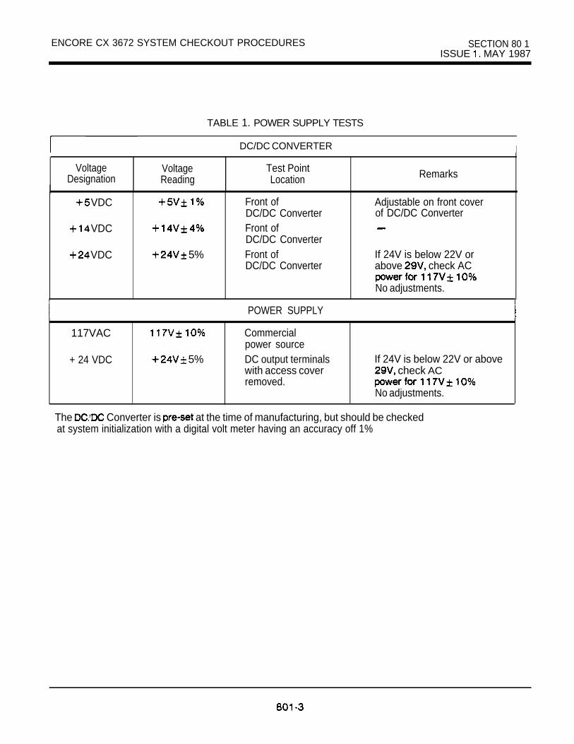
ENCORE CX 3672 SYSTEM CHECKOUT PROCEDURES SECTION 80 1ISSUE MAY 1987
TABLE 1. POWER SUPPLY TESTS
DC/DC CONVERTER I
VoltageDesignation
VoltageReading
Test PointLocation
VDC
VDC
VDC 5%
Front ofDC/DC ConverterFront ofDC/DC ConverterFront ofDC/DC Converter
Remarks
Adjustable on front coverof DC/DC Converter
If 24V is below 22V orabove check AC
No adjustments.
POWER SUPPLY
117VAC
+ 24 VDC 5%
Commercialpower sourceDC output terminalswith access coverremoved.
If 24V is below 22V or above check AC
No adjustments.
The Converter is at the time of manufacturing, but should be checkedat system initialization with a digital volt meter having an accuracy off 1%
K E Y
ENCORE CX 818 SERVICE INFORMATION
TABLE OF CONTENTS
DESCRIPTION PAGE1. INTRODUCTION. . . . . . . . . . . . . . . . . . . . . . . . . . . . . . . . . . . . . . . . . . . . . . . . , . . . . . . .
2. TEST EQUIPMENT AND TOOLS. . . . . . . . . . . . . . . . . . . . . . . . . . , , . . . . . . . . . . . . . . .
3. FAULT CONSIDERATIONS . . . . . . . . . . . . . . . . . . . . . . . . . . . . . . . . . . . . . . . . . . . . . . . .
4. SYSTEM FAILURES . . . . . . . . . . . . . . . . . . . . . . . . . . . . . . . . . . . . . . . . . . . . . . . . . . . . . . 1
5. KEY TELEPHONE FAILURES, . . . . . . . . . . . . . . . . . . . . . . . . . . . . . . . . . . . . . . . . . . . . . 1
6. LINE FAILURES. . . . . . . . . . . . . . . . . . . . . . . . . . . . . . . . . . . . . . . . . . . . . . . . . .
900-A

I KEY TELEPHONE SYSTEM ISSUE 2, SEPTEMBER 1988
1. INTRODUCTIONThis section provides common maintenance,troubleshooting and repair instructions for theENCORE CX 816 Key Telephone System. It isadvisable to use the latest issue manual andsupporting documentation whenever possible.A qualified person should perform allmaintenance and field upgrades.
2. TEST EQUIPMENT AND TOOLSThe following test equipment and tools arenecessary in performing maintenance and repair onthe ENCORE CX 816 Key Telephone System:
a. digital voltmeterb. test set (DTMF and rotary)c. standard telephone repair tools
3. FAULT CONSIDERATIONSReported problems come from a variety of peopleunder different conditions. Therefore, all troublereports should be examined thoroughly so the exactproblem is understood. Do not always suspect the816 equipment. To help isolate a fault from thereported description, the following information shouldbe investigated:
A. Were any changes made recently to thecustomer data base that could cause theproblem?
Were any changes made to cabling recently?C. Is the trouble associated with one circuit?
With a particular section or sections of circuits(i.e. CO lines, stations) or common to allcircuits?
D. Is the trouble intenittent or continuous?
4. SYSTEM Various problems will affect the entire system.These are normally related to the power supply,causing central processor or memory failure, inwhich case the KSU must be replaced.
5. KEY TELEPHONE FAILURESThe following questions should be consideredwhen isolating key telephone failures:Is the reported fault:
A. Present on 1 phone only?Check the wiring, programming, telephone, KSU.
B. Common to station numbers in pairs?Check wiring polarity and KSU.
C. Common to all stations?Check programming, wiring and KSU.
D. Common to a station that was recently moved orprogrammed?Check wiring and programming.
6. LINE FAILURESIs the reported fault:
A.
B.
C.
D.
Present on 1 line only?Check the affected CO line, plugconnections.Common to 2 or more lines?Check CO lines, wiring, KSU.Associated with key station?Check programming, phone, KSU.Associated signalling or incoming ring?Check programming and KSU.
1
KEY TELEPHONE SYSTEM ISSUE 2. SEPTEMBER 1988
ENCORE CX 3672 SERVICE INFORMATION
TABLE OF CONTENTS
DESCRIPTION PAGE
1. CENTRAL PROCESSOR BOARD (CPB) . . . . . . . . . . . . . . . . . . . . . . . . . . . . . . . . . . . .
2 DC/DC CONVERTER. . . . . . . . . . . . . . . . . . . . . . . . . . . . . . . . . . . . . . . . . . . . . . . . . . . . .
3. KEY INTERFACE BOARD . . . . . . . . . . . . . . . . . . . . . . . . . . . . . . . . . . . . . . . . . . . 3
4. OFF-HOOK VOICE ANNOUNCE BOARD (KIBOH). . . . . . . . . . . . . . . . . . . . . . . . . . . 3
5. CENTRAL OFFICE INTERFACE BOARD (COB) . . . . . . . . . . . . . . . . . . . . . . . . . . . . .
6. SINGLE LINE INTERFACE BOARD (SIB) . . . . . . . . . . . . . . . . . . . . . . . . . . . . . . . . . . .
7. SINGLE LINE RING GENERATOR ANDMESSAGE WAIT POWER SUPPLY (RGU) . . . . . . . . . . . . . . . . . . . . . . . . . . . . . . . . . . 4
8. APPLICATION BOARD (APL). . . . . . . . . . . . . . . . . . . . . . . . . . . . . . . . . . . . . . . . . . . . . . 4
RECEIVER/SENDER MODULE (RSM). . . . . . . . . . . . . . . . . . . . . . . . . . . . . . . . . . . . . . . . 4
10. MODULE (SDI) . . . . . . . . . . . . . . . . . . . . . . . . . . . . . . . . . . . . . . . . . . . . . . . . . .
EMERGENCY TRANSFER MODULE (BTU) . . . . . . . . . . . . . . . . . . . . . . . . . . . . . . . . . 5

ENCORE CX 3672 SERVICE INFORMATION
1. CENTRAL PROCESSOR BOARD
CONTROL OPTIONS FAULTCONDITIONS
1. Central Contains 8 process Switch 1 1. Complete systemColor Code: Processor Unit running indicators failure.
W O W (CPU) to which Protects contents 2. Erroneouscalfcontrol system indicate various of data base. processing.operation. conditions of the 3. Inoperative features
2. Read Only system. Allows update of in system operation.Memory (ROM) LED the data base from 4. Partial failures inwith factory set Dependability/ station 100. system operation.
Recovery, Switch 2 5. Continual. system3. Random flickers on/off in restarts.
Access normal operation. For 6. Failure of SMDR.Memory (RAM) LED 2 equipped to send 7. Loss of uniqueprotected by a Ringing, will fbsh CTS signal. customer data baselithium battery. steady when ring programming.
4. Hard Restart scan is Is terminalswitch for functioning.manual system Switch 3 restart. Timers, will flicker ON
5. Provides when timers are Allows traceRS232 port operating. output.for SMDR. OFF
Monitor No trace output.Switch 4
LCDNo soft restart.
processing.Allows soft restart.
Administration Switch 5
Idle the system stops
and LED1 Switch 6
ROM
RAM failure. type
901-l

SECTION 90 ENCORE 3672 SERVICE INFORMATIONISSUE 2. SEPTEMBER 1988
1. CENTRAL PROCESSOR BOARD (CPB) (CONT’D)
FUNCTION
2. DC/DC CONVERTER
DC/DC Converter
DC/DC Converterwith
4v
Provides LEDindiitions itvoltages
Provides BGM 1
connections.
CONTROL
1. Receives24 from
2. volume.
3. Has ON/OFFswitch.
OPTIONS
Switch 7
SMDR goes to
SMDR goes tofirst port.
Switch 8
winnot initialize.
be
2. Loss of
FAULTCONDITIONS
1. failure.

ISSUE 2. SEPTEMBER 1988
3. KEY INTERFACE BOARD (KIB)
Color Code:Green
FUNCTION CONTROLI
OPTIONS
Rovides interfacefor 8 key
Busy state LED thatmonitors forbusy condifon.Service switch with
mode.
4. OFF-HOOK VOICE ANNOUNCE BOARD (KIBOH)
Provides interfacefor 8 keytelephones andprovides theoff-hook voicefeature for thosetelephones.
Busy state LED that Nonemonitors circuitsfor busy condition.Normal/Serviceswitch.
5. CENTRAL OFFICE INTERFACE BOARD (COB)
Color Code:White
FAULT
1. Unable to receiveintercom dial tone.
2. Poor transmissioncharacteristics.
3. Key Setinoperative.
4. Key telephone to invoke
features.5. No LED indications.
Provides interface Busy state ED that None 1 . Unable to receivefor 8 monitors each CO tone.lines. line for 2. Unable to break
ringing, busy and CO tone.idle conditions. 3. CO notService switch with ringing.
4. mode.
Color Code:
Green
1. Key telephoneset inoperative.
2. Poor transmissioncharacteristics.
3. Loss of Off-Hookvoice announce.
6. SINGLE LINE INTERFACE BOARD (SIB)
Provides interfacefor 8 Contains the
intercom paths.
with MW
1. SLT can’t receivedii tone.
2. Poor transmissioncharacteristics.
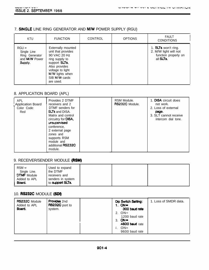
7. LINE RING GENERATOR AND POWER SUPPLY (RGU)
KTU FUNCTION CONTROL OPTIONSFAULT
CONDITIONS
RGU Externally mounted 1. won’t ring.Single Line unit that provides 2. M/W light will notRing Generator 90 VAC 20 Hz function properly onand Power ring supply to all
support Also providesvoltage to light
lights whenSIB cardsare used.
8. APPLICATION BOARD (APL)
APL Application Board
Color Code:Red
Provides 2 DTMFreceivers and 2DTMF senders for
and DISA.Matrix and controlcircuitry for
conference,2 external pagezones andsupports RSMmodule andadditional module.
RSM Module. Module.
1. circuit doesnot work.
2. Loss of external
3. SLT cannot receiveintercom dial tone.
9. RECEIVER/SENDER MODULE
RSM Single Line.
ModuleAdded to APL
Used to expandthe DTMFreceivers andsenders in systemto
10. MODULE
ModuleAdded to APL
2nd port to
system.2. ON=
1200 baud rate3.
rate4 . ON=
9600 baud rate
1. Loss of SMDR data.

11. EMERGENCY TRANSFER MODULE (ETU)
FUNCTION CONTROL
ETUEmergencyTransfer Module.
Provides relaytransfer circuits forup to 6 CO linesin the event of apower orprocessor failure.Facilitates loud bellringing.
12. ENHANCED PROCESSOR BOARD (EPB)Refer to Central Processor Board (CPB), paragraph 1.
OPTIONS
Manual switch usedfor activating the
for testingpurposes.
FAULTCONDITIONS
1. Power failuretransfer does notfunction.
2. Loud bells do notring.
901-S

E N C O R E TECHNICAL MANUALKEY TELEPHONE SYSTEM ISSUE 2. NOVEMBER
RECORD OF CHANGES
This Record of Changes page is used to keep you up-to-date with changes and variations in ENCORE CXequipment. As Technical Facts pertaining to the ENCORE Key Telephone System are issued, list them on thisRecord of Changes page and follow the instructions given in the Technical Facts.
The combination of Technical Facts and Record of Changes will provide you with a of allchanges made to the ENCORE CX Key Telephone System.
To insure that you are using the most current instructions when installing or equipment, check theRecord of Changes page and study all pertinent Technical Facts.
LEGEND: 1. Information previously contained in this Technical Facts has been integrated into the body of thiimanual. Therefore, this Technical Facts is not contained in the Technical section thismanual.
The entire Technical Facts has been inducted in the Technical Facts section of this manual.Information previously attached to this Technical Facts has been integrated the body of thismanual. The header sheet is not contained in the Technical this manual.
The Technical Facts is listed on the Record of Changes However, Facts is notinduded in the Facts section of this manuai.
DATE DESCRIPTION . I
cx 3872
TF1818 3672 Software Release
TF1818
TF1819 12-23-87
ENCORE 2872 SIB Power Is On
CX 2872 Release 2.04
TF1822
Program
TF1828
TF1827
Cost Routing (LCR) Package
CX 3872
TF1828 Of -1548
07-l 8-88 for the ENCORE System
for ENCORE
CX 818 Upgrade
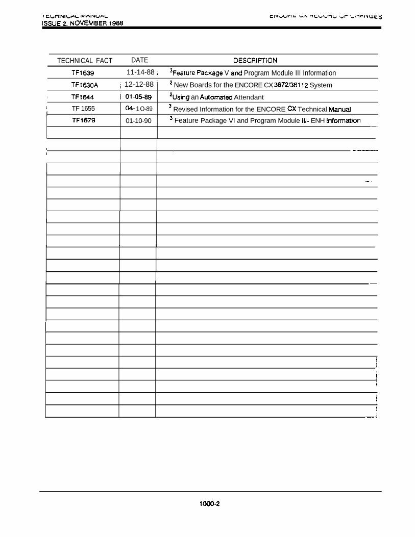
TECHNICAL FACT DATE
11-14-88 V Program Module III Information
12-12-88 New Boards for the ENCORE CX System
an Attendant
TF 1655I
1 O-89 Revised Information for the ENCORE Technical
01-10-90 Feature Package VI and Program Module ENH
Top Related