


Languages
Pages
Legal

Enabling Advanced Capabilities for Distributed Energy Resources
Takeaways from the Interconnection Standard IEEE 1547 Full Revision
November 8th, 2017
• Introduction to Distribution Interconnection Standards
• Changes in Full-Revision of IEEE 1547
• Local System Support– Real and Reactive Capabilities
• Bulk System Support– Voltage and Frequency Ride-Through
• Interoperability– DER Local Communications Interface
Overview
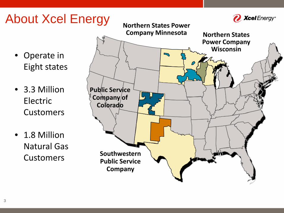
About Xcel Energy
3
Northern States Power Company Minnesota
Public Service Company of
Colorado
Southwestern Public Service
Company
Northern States Power Company
Wisconsin• Operate in
Eight states
• 3.3 Million Electric Customers
• 1.8 Million Natural Gas Customers
Transmission
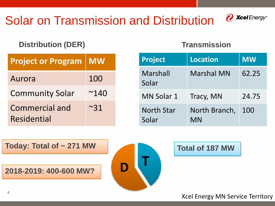
Solar on Transmission and Distribution
4
Project Location MW
Marshall Solar
Marshal MN 62.25
MN Solar 1 Tracy, MN 24.75
North StarSolar
North Branch,MN
100
Total of 187 MW
Distribution (DER)
Project or Program MW
Aurora 100
Community Solar ~140
Commercial and Residential
~31
Today: Total of ~ 271 MW
D T
Xcel Energy MN Service Territory
2018-2019: 400-600 MW?
DER Interconnection Standard Update IEEE 1547 Full Revision
5
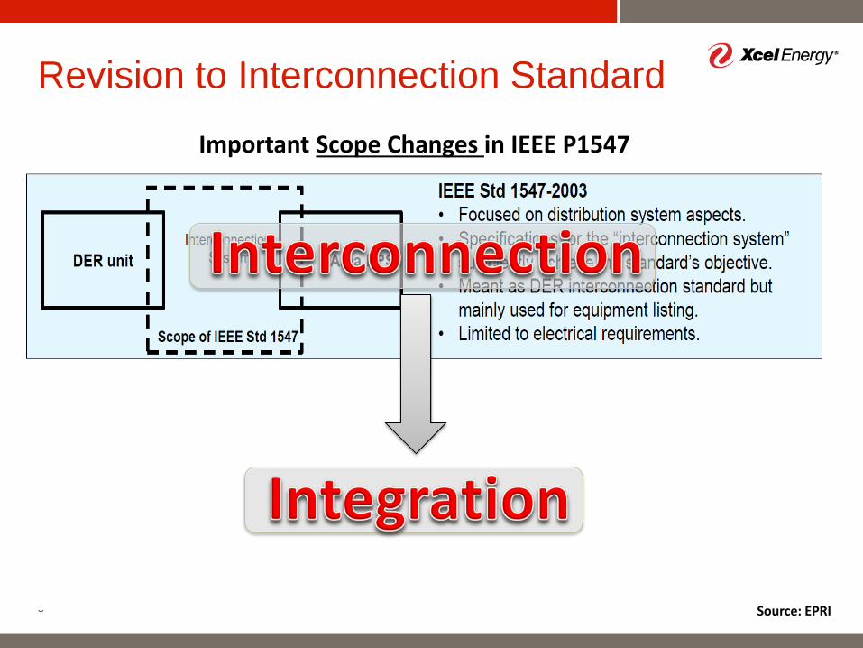
Revision to Interconnection Standard
6
Important Scope Changes in IEEE P1547
Source: EPRI
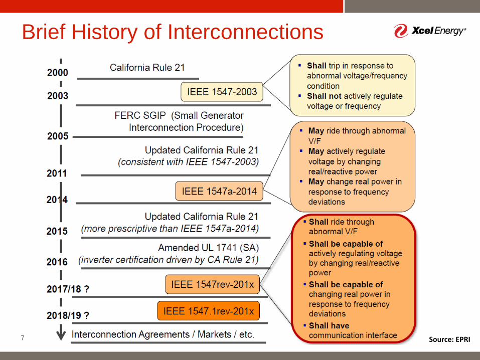
Brief History of Interconnections
7 Source: EPRI
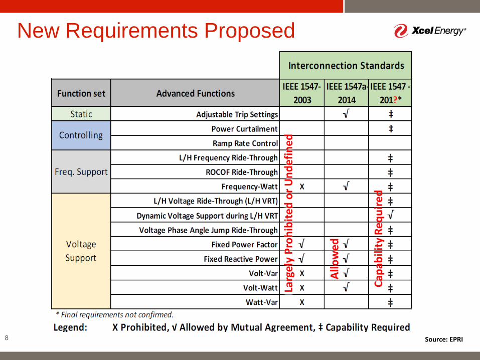
New Requirements Proposed
8 Source: EPRI
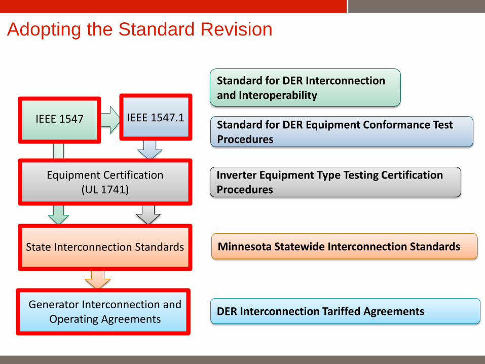
Adopting the Standard Revision
Generator Interconnection and Operating Agreements
State Interconnection Standards
Equipment Certification (UL 1741)
IEEE 1547 IEEE 1547.1
Standard for DER Interconnection and Interoperability
Standard for DER Equipment Conformance Test Procedures
Inverter Equipment Type Testing Certification Procedures
Minnesota Statewide Interconnection Standards
DER Interconnection Tariffed Agreements
10
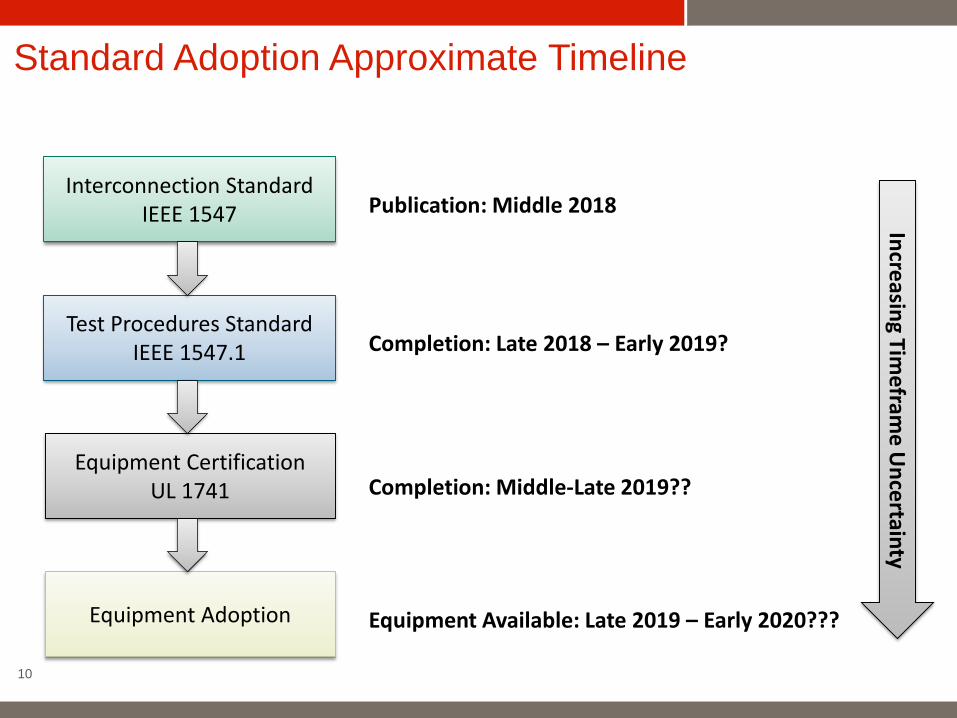
Equipment Certification UL 1741
Interconnection StandardIEEE 1547
Test Procedures StandardIEEE 1547.1
Equipment Adoption
Standard Adoption Approximate Timeline
Publication: Middle 2018
Completion: Late 2018 – Early 2019?
Completion: Middle-Late 2019??
Equipment Available: Late 2019 – Early 2020???
Increasing Timefram
e Uncertainty
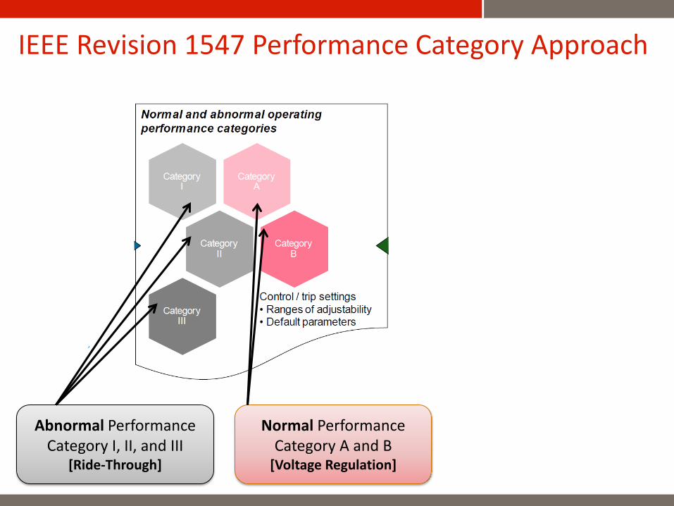
IEEE Revision 1547 Performance Category Approach
Minnesota Public Utilities Commission
Normal PerformanceCategory A and B
[Voltage Regulation]
Abnormal Performance Category I, II, and III
[Ride-Through]
Local System SupportReal and Reactive Power Functions
12
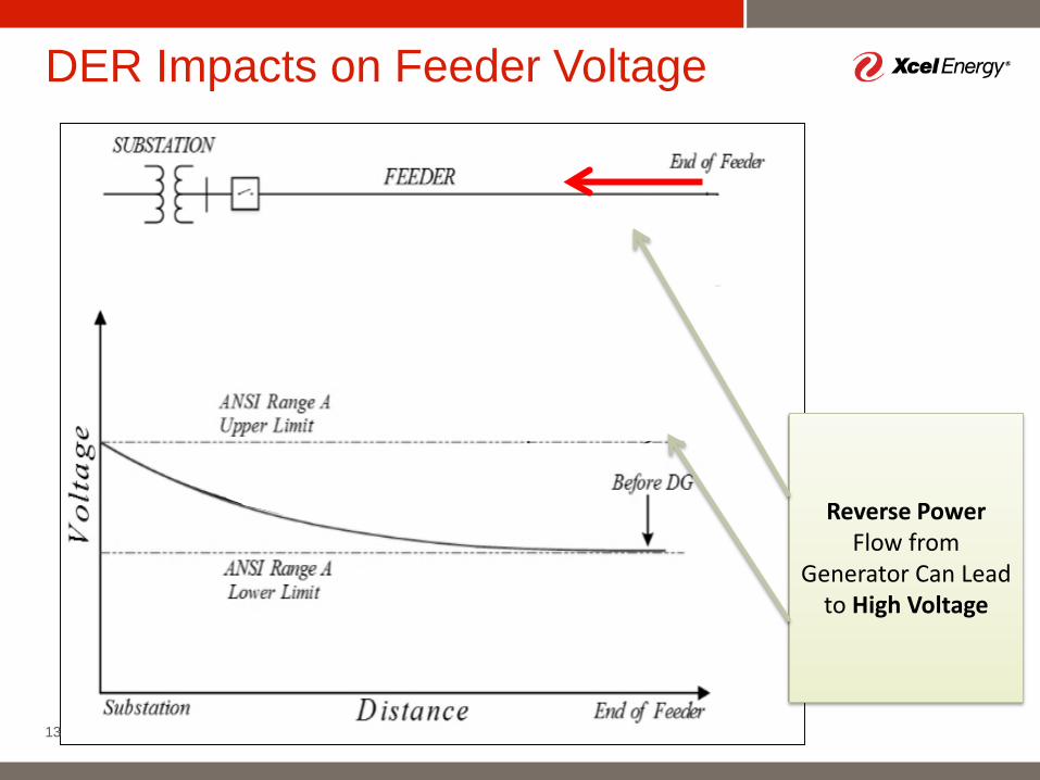
DER Impacts on Feeder Voltage
13
Reverse Power Flow from
Generator Can Lead to High Voltage
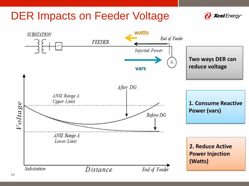
DER Impacts on Feeder Voltage
14
Two ways DER can reduce voltage
1. Consume Reactive Power (vars)
vars
2. Reduce Active Power Injection (Watts)
watts
Category B Requires Capability for All Functions
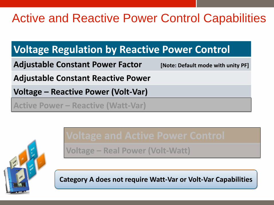
Active and Reactive Power Control Capabilities
Voltage Regulation by Reactive Power ControlAdjustable Constant Power Factor [Note: Default mode with unity PF]
Adjustable Constant Reactive PowerVoltage – Reactive Power (Volt-Var) Active Power – Reactive (Watt-Var)
Voltage and Active Power ControlVoltage – Real Power (Volt-Watt)
Category A does not require Watt-Var or Volt-Var Capabilities
16
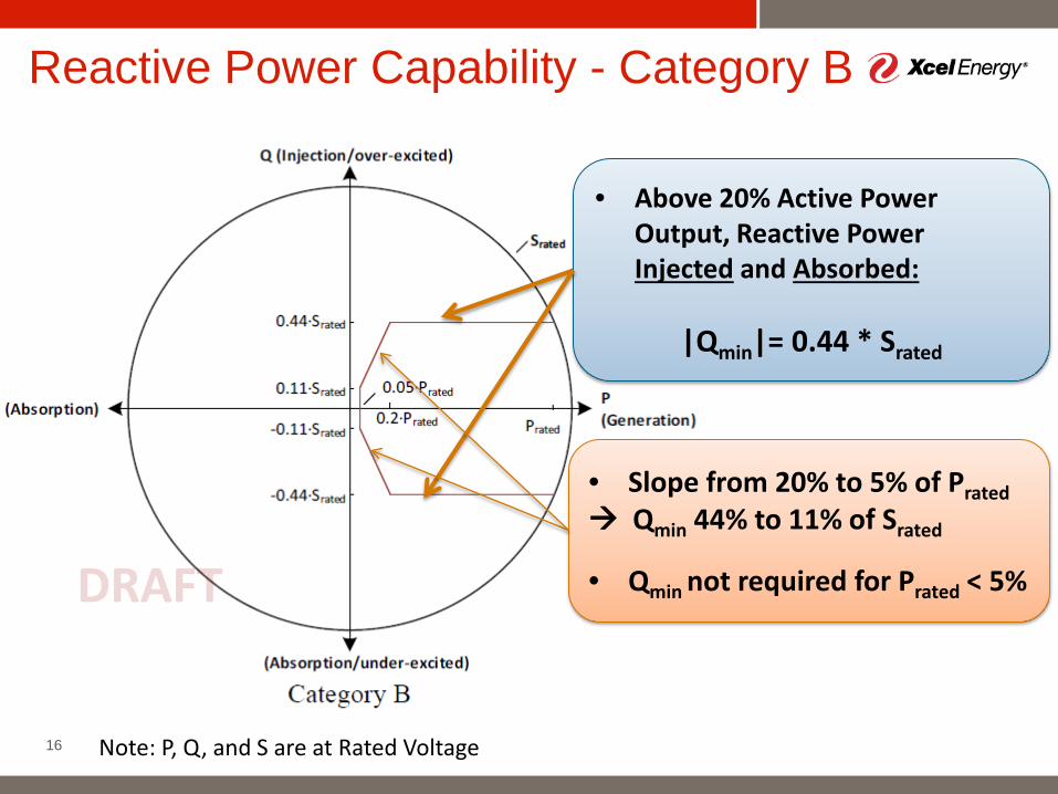
Reactive Power Capability - Category B
Note: P, Q, and S are at Rated Voltage
• Above 20% Active Power Output, Reactive Power Injected and Absorbed:
|Qmin|= 0.44 * Srated
• Slope from 20% to 5% of Prated Qmin 44% to 11% of Srated
• Qmin not required for Prated < 5%
17
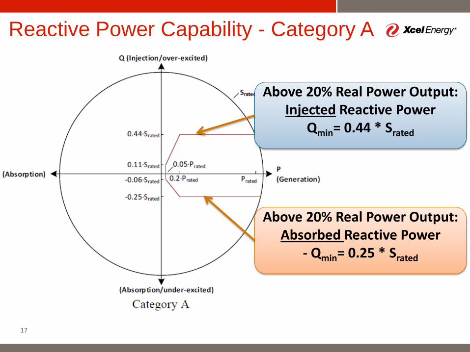
Reactive Power Capability - Category A
Above 20% Real Power Output:Injected Reactive Power
Qmin= 0.44 * Srated
Above 20% Real Power Output:Absorbed Reactive Power
- Qmin= 0.25 * Srated
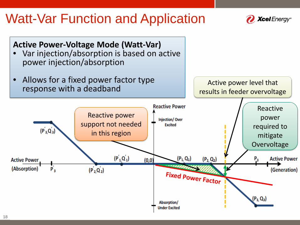
Watt-Var Function and Application
18
Active power level that results in feeder overvoltage
Reactive power support not needed
in this region
Active Power-Voltage Mode (Watt-Var)• Var injection/absorption is based on active
power injection/absorption
• Allows for a fixed power factor type response with a deadband
Reactive power
required to mitigate
Overvoltage
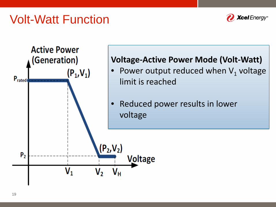
Volt-Watt Function
19
Voltage-Active Power Mode (Volt-Watt)• Power output reduced when V1 voltage
limit is reached
• Reduced power results in lower voltage
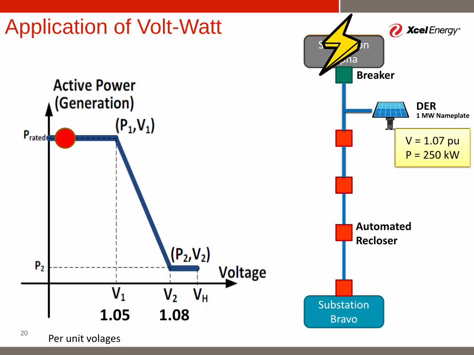
Application of Volt-Watt
20
Substation Alpha
Substation Bravo
DER1 MW Nameplate
Breaker
Automated Recloser
Substation Alpha
1.05 1.08
V = 1.03 p.u.P = 1 MW
V = 1.07 puP = 250 kW
Per unit volages
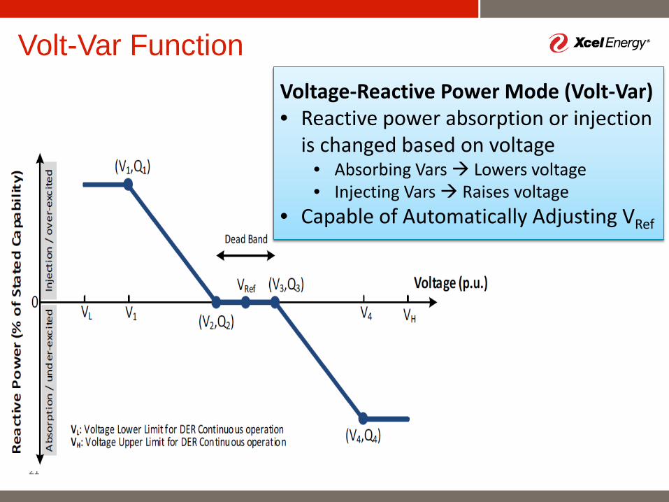
Volt-Var Function
21
Voltage-Reactive Power Mode (Volt-Var)• Reactive power absorption or injection
is changed based on voltage • Absorbing Vars Lowers voltage• Injecting Vars Raises voltage
• Capable of Automatically Adjusting VRef
22
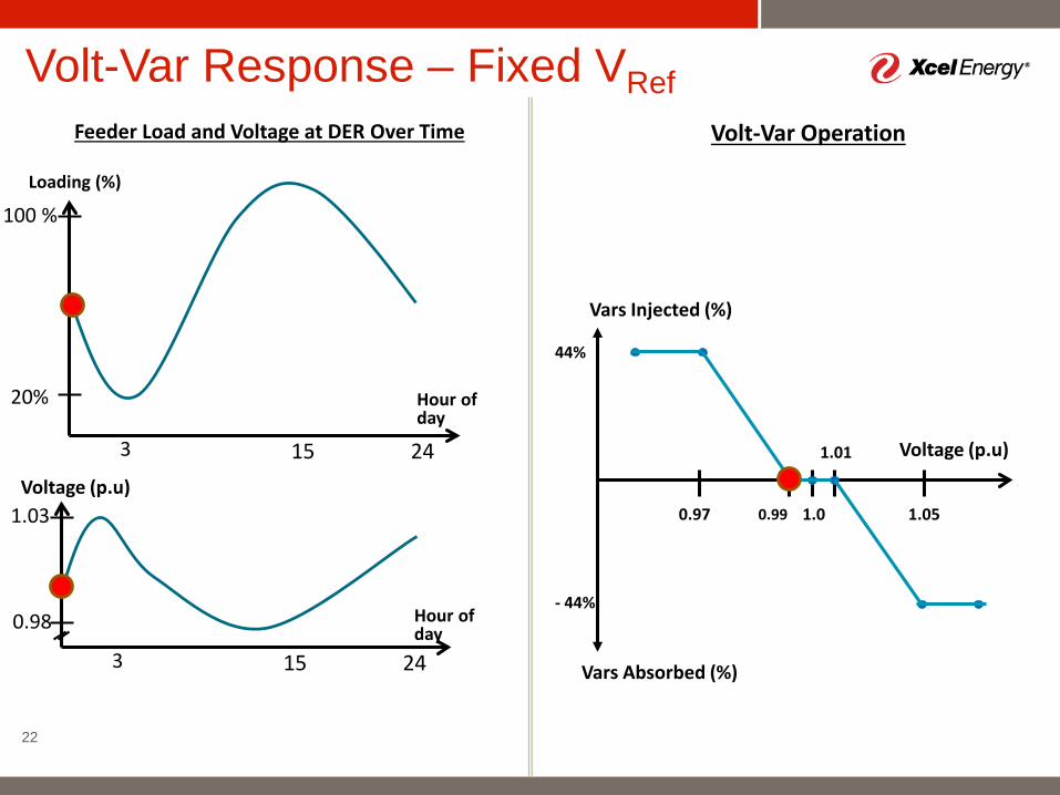
Loading (%)
Hour of day
3 15 24Voltage (p.u)
Hour of day
3 15 24
100 %
20%
1.03
0.98
Feeder Load and Voltage at DER Over Time
Volt-Var Response – Fixed VRef
1.0
Voltage (p.u)
Vars Injected (%)
0.99
1.01
1.050.97
Vars Absorbed (%)
Volt-Var Operation
44%
- 44%
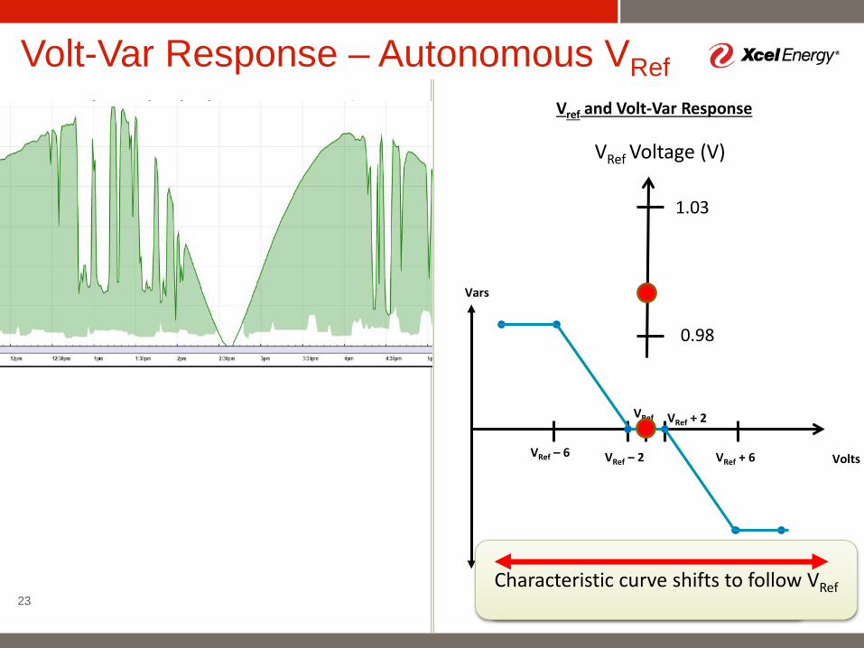
23
Loading (%)
Hour of day
3 15 24Voltage (V)
Hour of day
3 15 24
100 %
20%
1.03
0.98
VRef – 2
VRef + 2VRef
Volts
Vars
Feeder Load and Voltage at DER Over Time
Volt-Var Response – Autonomous VRef
VRef – 6 VRef + 6
VRef Voltage (V)
1.03
0.98
VREF autonomous response has low-pass filter characteristics
Vref and Volt-Var Response
Characteristic curve shifts to follow VRef
Bulk System Support
24
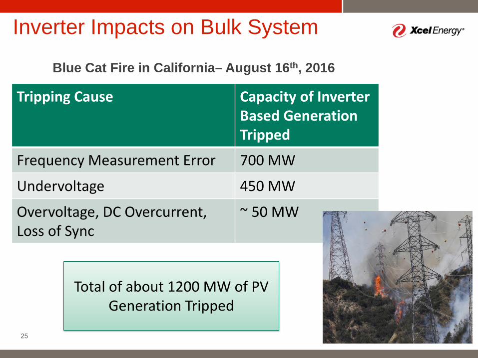
Blue Cat Fire in California– August 16th, 2016
Inverter Impacts on Bulk System
25
Tripping Cause Capacity of InverterBased GenerationTripped
Frequency Measurement Error 700 MW
Undervoltage 450 MW
Overvoltage, DC Overcurrent, Loss of Sync
~ 50 MW
Total of about 1200 MW of PV Generation Tripped
26
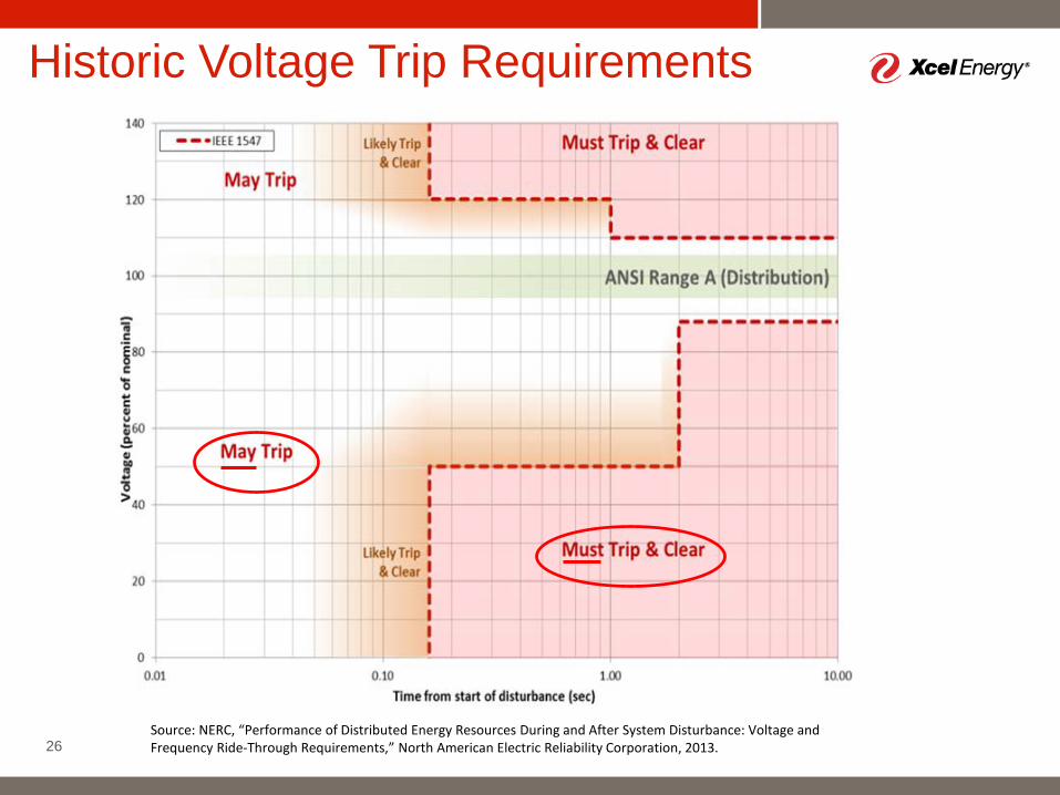
Historic Voltage Trip Requirements
Source: NERC, “Performance of Distributed Energy Resources During and After System Disturbance: Voltage and Frequency Ride-Through Requirements,” North American Electric Reliability Corporation, 2013.
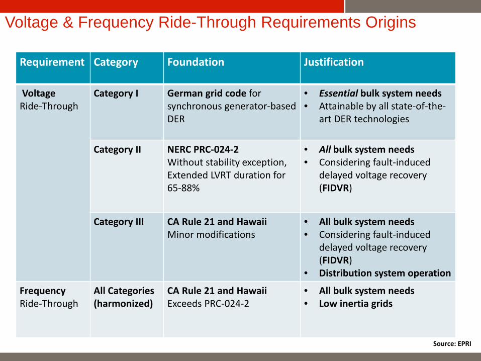
Voltage & Frequency Ride-Through Requirements Origins
Requirement Category Foundation Justification
VoltageRide-Through
Category I German grid code forsynchronous generator-basedDER
• Essential bulk system needs• Attainable by all state-of-the-
art DER technologies
Category II NERC PRC-024-2Without stability exception, Extended LVRT duration for65-88%
• All bulk system needs• Considering fault-induced
delayed voltage recovery (FIDVR)
Category III CA Rule 21 and HawaiiMinor modifications
• All bulk system needs• Considering fault-induced
delayed voltage recovery (FIDVR)
• Distribution system operation
Frequency Ride-Through
All Categories(harmonized)
CA Rule 21 and HawaiiExceeds PRC-024-2
• All bulk system needs• Low inertia grids
Source: EPRI
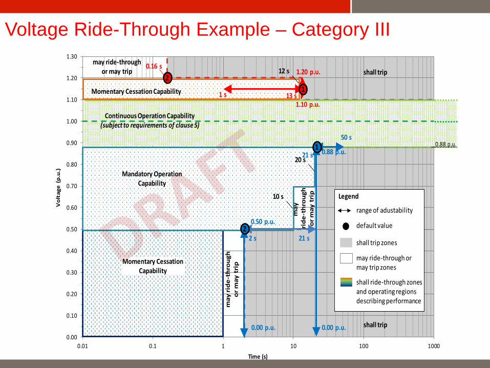
Voltage Ride-Through Example – Category III
0.00
0.10
0.20
0.30
0.40
0.50
0.60
0.70
0.80
0.90
1.00
1.10
1.20
1.30
0.01 0.1 1 10 100 1000
Vol
tage
(p.
u.)
Time (s)
Momentary Cessation Capability
shall trip1.20 p.u.0.16 s
13 s1.10 p.u.
0.00 p.u.
0.88 p.u.
21 s
0.00 p.u.
0.50 p.u.
Continuous Operation Capability(subject to requirements of clause 5)
Mandatory OperationCapability
shall trip
10 s
2 s
2
1 s1
2
may ride-throughor may trip
Momentary CessationCapability
20 s21 s
50 s1
may
ride
-thr
ough
or m
ay t
rip
12 s
0.88 p.u.
may
ri
de-t
hrou
ghor
may
tri
p Legend
range of adustability
default value
shall trip zones
may ride-through ormay trip zones
shall ride-through zonesand operating regionsdescribing performance
29
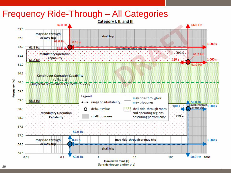
Frequency Ride-Through – All Categories
30
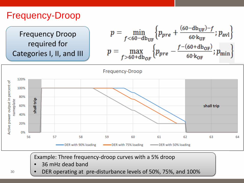
Frequency-Droop
Frequency Droop required for
Categories I, II, and III
Example: Three frequency-droop curves with a 5% droop• 36 mHz dead band • DER operating at pre-disturbance levels of 50%, 75%, and 100%
Interoperability
31
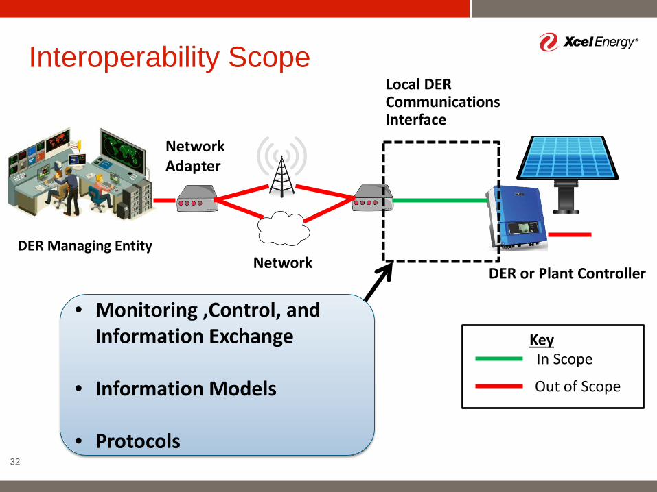
Interoperability Scope
32
DER Managing Entity
DER or Plant Controller
Network Adapter
Network
In Scope
Out of Scope
Key
• Monitoring ,Control, and Information Exchange
• Information Models
• Protocols
Local DER Communications Interface
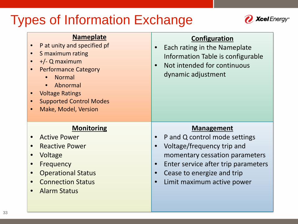
Types of Information Exchange
33
Nameplate• P at unity and specified pf• S maximum rating• +/- Q maximum • Performance Category
• Normal • Abnormal
• Voltage Ratings• Supported Control Modes• Make, Model, Version
Configuration• Each rating in the Nameplate
Information Table is configurable• Not intended for continuous
dynamic adjustment
Monitoring • Active Power• Reactive Power • Voltage • Frequency• Operational Status• Connection Status• Alarm Status
Management• P and Q control mode settings• Voltage/frequency trip and
momentary cessation parameters• Enter service after trip parameters• Cease to energize and trip• Limit maximum active power
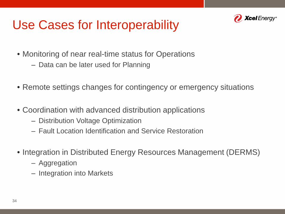
• Monitoring of near real-time status for Operations– Data can be later used for Planning
• Remote settings changes for contingency or emergency situations
• Coordination with advanced distribution applications– Distribution Voltage Optimization– Fault Location Identification and Service Restoration
• Integration in Distributed Energy Resources Management (DERMS)– Aggregation – Integration into Markets
Use Cases for Interoperability
34
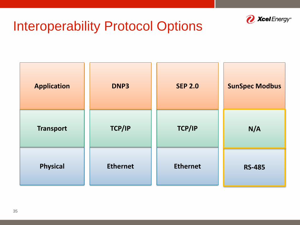
Interoperability Protocol Options
35
Ethernet
TCP/IP
DNP3
Ethernet
TCP/IP
SEP 2.0
Ethernet
SunSpec Modbus
Physical
Transport
Application
TCP/IP
RS-485
N/A
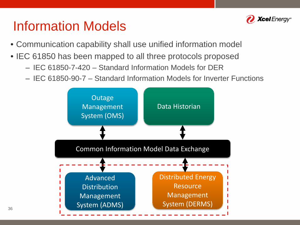
• Communication capability shall use unified information model• IEC 61850 has been mapped to all three protocols proposed
– IEC 61850-7-420 – Standard Information Models for DER– IEC 61850-90-7 – Standard Information Models for Inverter Functions
Information Models
36
Common Information Model Data Exchange
Advanced Distribution
Management System (ADMS)
Outage Management System (OMS)
Distributed Energy Resource
Management System (DERMS)
Data Historian
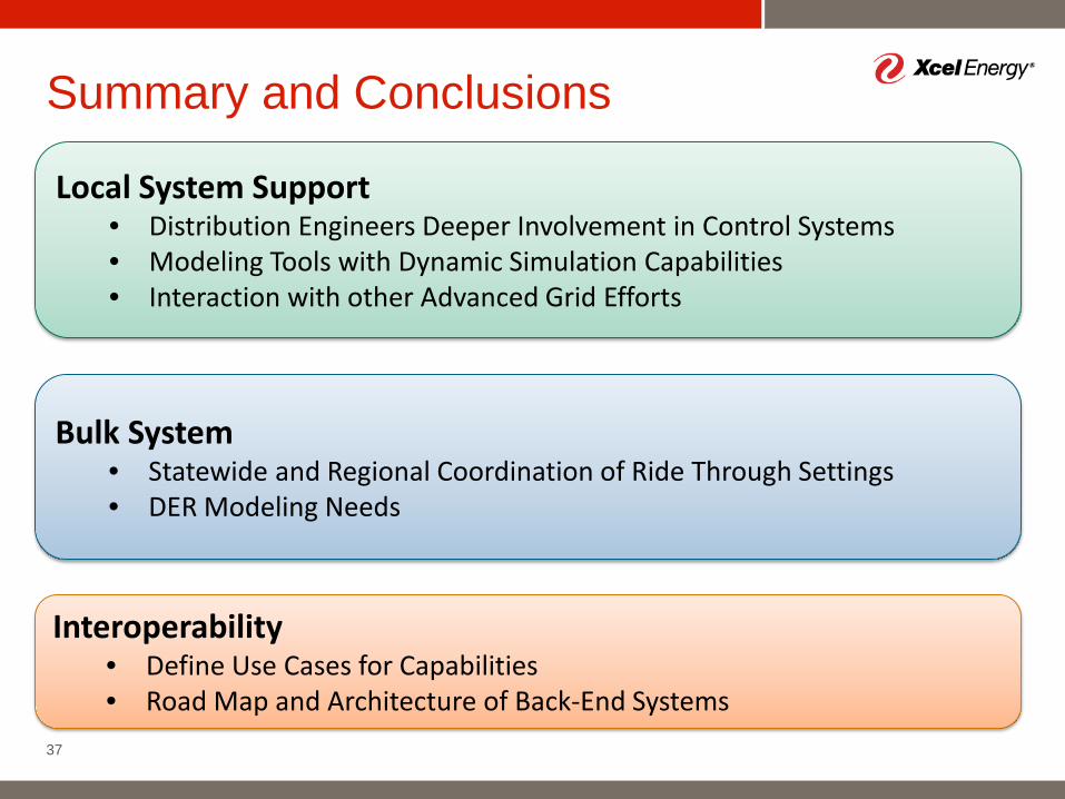
Summary and Conclusions
37
Local System Support• Distribution Engineers Deeper Involvement in Control Systems • Modeling Tools with Dynamic Simulation Capabilities• Interaction with other Advanced Grid Efforts
Bulk System• Statewide and Regional Coordination of Ride Through Settings• DER Modeling Needs
Interoperability• Define Use Cases for Capabilities• Road Map and Architecture of Back-End Systems
Top Related