


Languages
Pages
Legal


Emission et réception d’ondes électromagnétiques

Dipôle de Hertz

1887 : En cherchant à mettre en évidence les ondes électromagnétiques, Hertz découvre l’effet photoélectrique


Dipôle de Hertz

Relations entre champs et potentiels
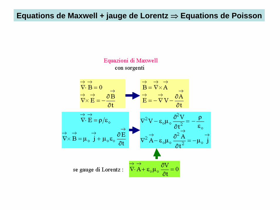
Equations de Maxwell + jauge de Lorentz ⇒ Equations de Poisson
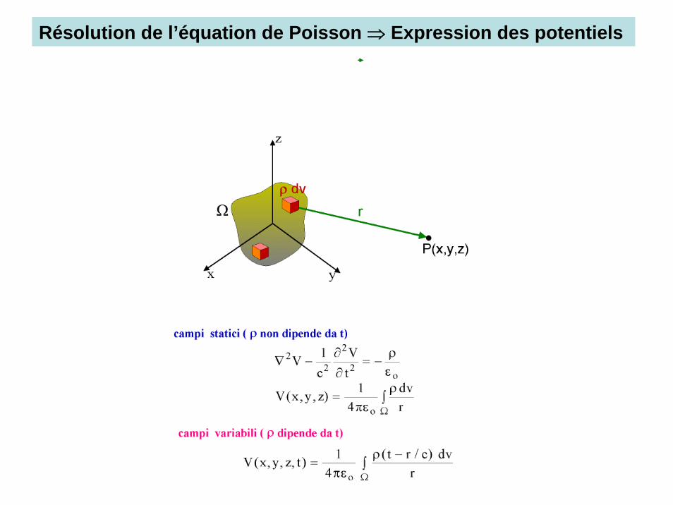
Résolution de l’équation de Poisson ⇒ Expression des potentiels
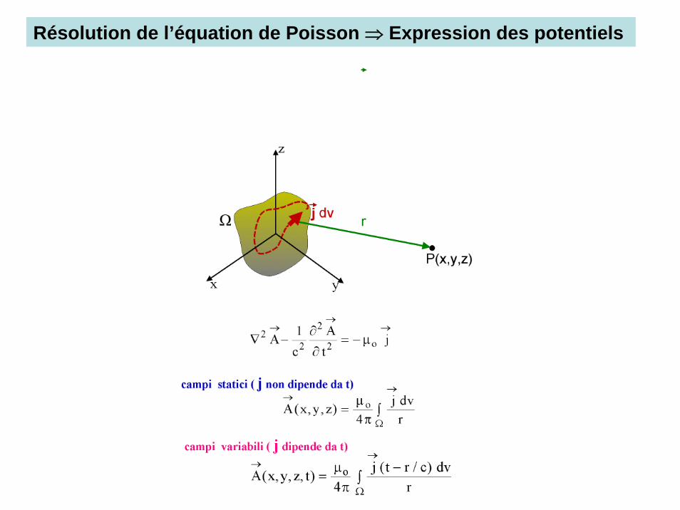
Résolution de l’équation de Poisson ⇒ Expression des potentiels

Détermination du rayonnement du dipôle
0 ( / )4
p t r cAr
μ −=
π
r&ur
V déterminé par intégration de la jauge de Lorentz
Les champs sont déterminés par intégration des relations entre champs et potentiels
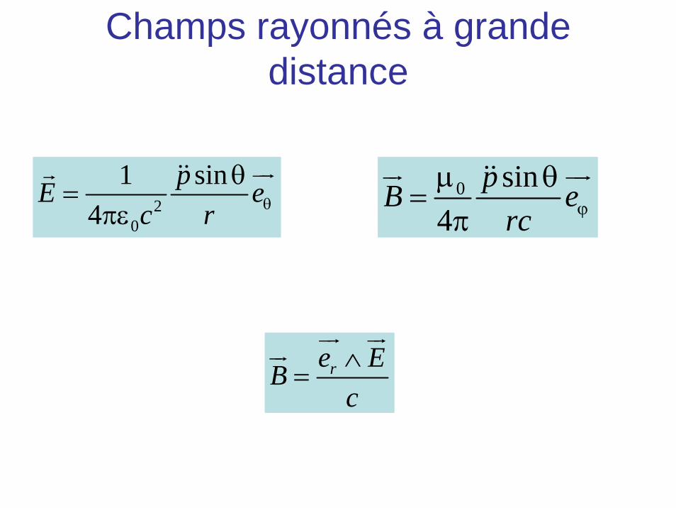
Champs rayonnés à grande distance
20
1 sin4
pE ec r θ
θ=
πε
uurr && 0 sin4
pB erc ϕ
μ θ=
π
ur uur&&
re EBc∧
=
ur urur
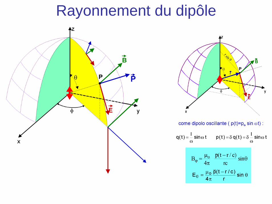
Rayonnement du dipôle

Historique
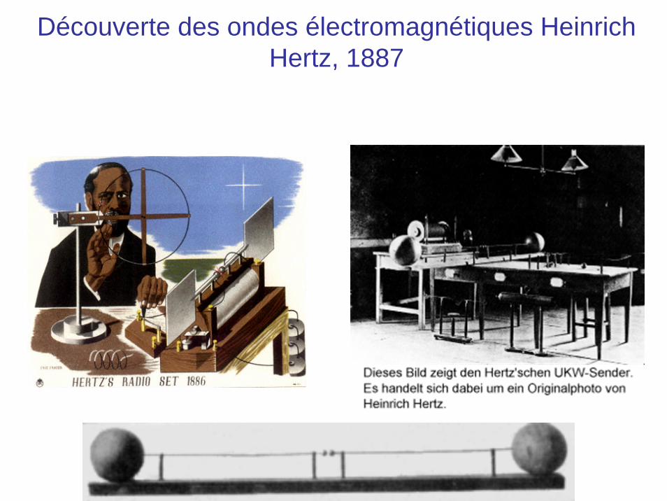
Découverte des ondes électromagnétiques Heinrich Hertz, 1887

Historique

Principe de l’expérience de Hertz
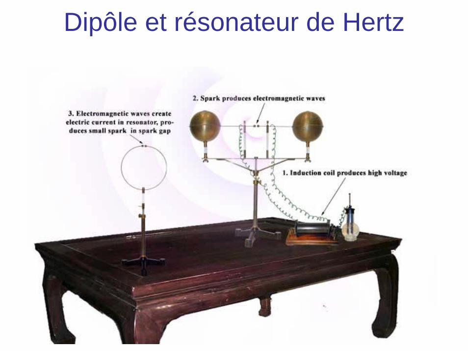
Dipôle et résonateur de Hertz
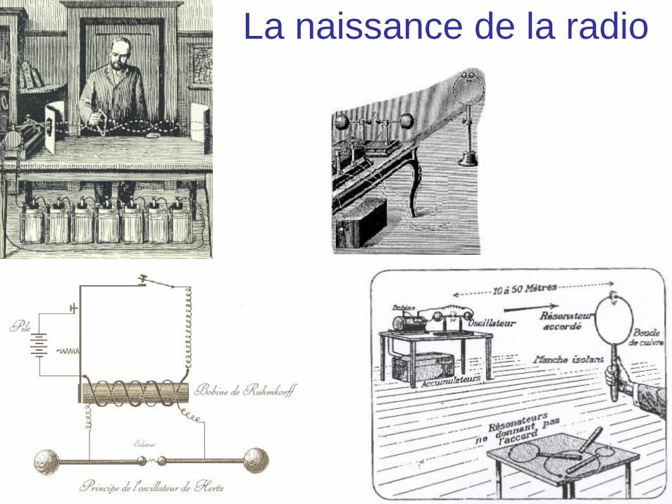
La naissance de la radio
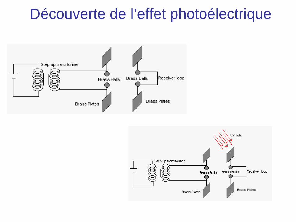
Découverte de l’effet photoélectrique
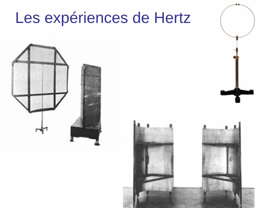
Les expériences de Hertz

Le Radar

Principe du radar
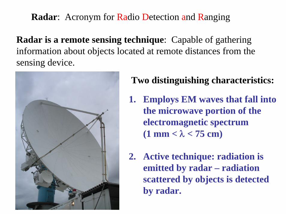
Radar: Acronym for Radio Detection and Ranging
Radar is a remote sensing technique: Capable of gathering information about objects located at remote distances from the sensing device.
Two distinguishing characteristics:
1. Employs EM waves that fall into the microwave portion of the electromagnetic spectrum(1 mm < λ < 75 cm)
2. Active technique: radiation is emitted by radar – radiation scattered by objects is detected by radar.
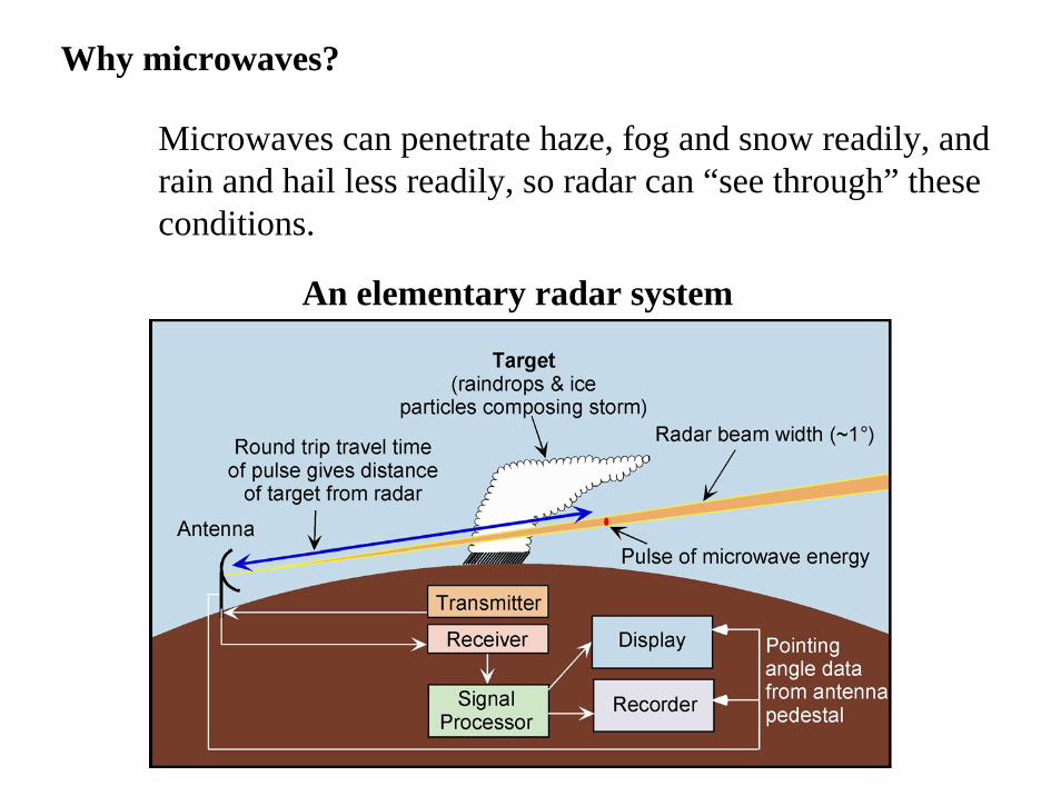
Why microwaves?
Microwaves can penetrate haze, fog and snow readily, and rain and hail less readily, so radar can “see through” these conditions.
An elementary radar system
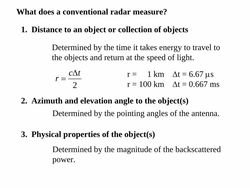
What does a conventional radar measure?
1. Distance to an object or collection of objects
Determined by the time it takes energy to travel to the objects and return at the speed of light.
2tcr Δ
=
2. Azimuth and elevation angle to the object(s)Determined by the pointing angles of the antenna.
3. Physical properties of the object(s)
Determined by the magnitude of the backscattered power.
r = 1 km Δt = 6.67 μsr = 100 km Δt = 0.667 ms
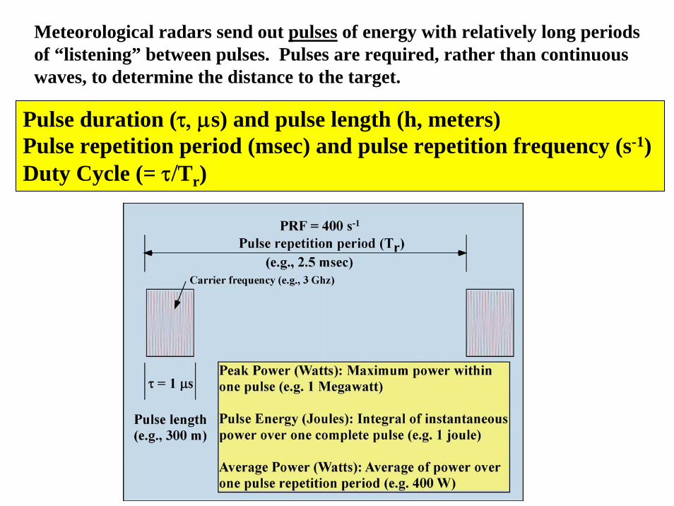
Pulse duration (τ, μs) and pulse length (h, meters)Pulse repetition period (msec) and pulse repetition frequency (s-1)Duty Cycle (= τ/Tr)
Meteorological radars send out pulses of energy with relatively long periods of “listening” between pulses. Pulses are required, rather than continuous waves, to determine the distance to the target.
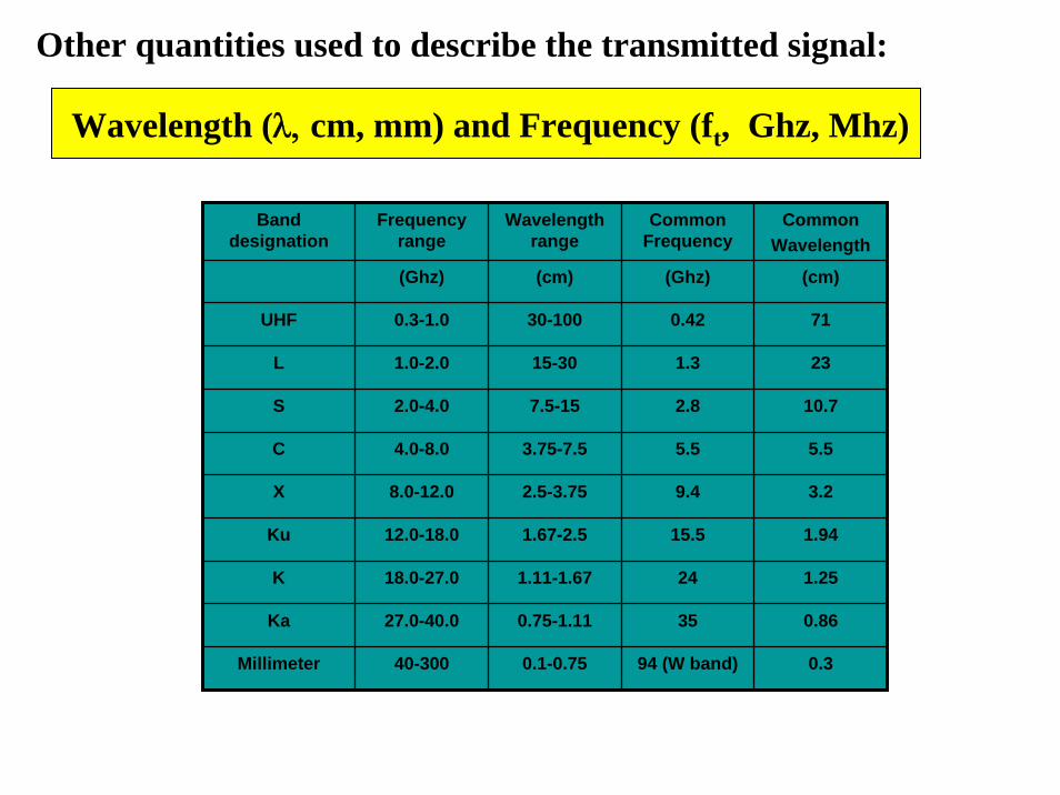
Other quantities used to describe the transmitted signal:
Wavelength (λ, cm, mm) and Frequency (ft, Ghz, Mhz)
Band designation
Frequency range
Wavelength range
Common Frequency
CommonWavelength
(Ghz) (cm) (Ghz) (cm)
UHF 0.3-1.0 30-100 0.42 71
L 1.0-2.0 15-30 1.3 23
S 2.0-4.0 7.5-15 2.8 10.7
C 4.0-8.0 3.75-7.5 5.5 5.5
X 8.0-12.0 2.5-3.75 9.4 3.2
Ku 12.0-18.0 1.67-2.5 15.5 1.94
K 18.0-27.0 1.11-1.67 24 1.25
Ka 27.0-40.0 0.75-1.11 35 0.86
Millimeter 40-300 0.1-0.75 94 (W band) 0.3

Major wavelength choice issues:
1. Size of equipment2. Attenuation3. Size of scatterers relative to
wavelength (Rayleigh vs Miescattering)
4. Peak power (without arcing inwaveguide – e.g., 3 MW in unpressurized waveguide for S band, 0.4 MW for K band)
K (0.8 cm) band radar antennaS (10 cm) band radar antenna

ModulatorStores power
Between pulses
MagnetronGenerates
Microwaveswhen high
voltage pulse sent from
Modulator
FrequencyDetermined
by characteristicsof magnetron
DuplexerFast actingSwitch that
protectssensitive
receiver fromhigh energypulse frommagnetron
STALOOscillatorGeneratesa steady
frequency
COHOOscillatesat lower
frequencywith samephase as
transmittedpulse

Quantities used to describe weather echoes
Wavelength (λ ± Δ λ, cm, mm) and Frequency (ft ± fD) Ghz, Mhz)
fD is the Doppler shift, the change in frequency that occursbecause scatterers are moving toward or away from the radar.
Doppler shift is typically no more than a few kilohertz, whileThe transmitted frequency is typically gigahertz!
3,000,000,000 3,000,001,000

Quantities used to describe weather echoes
Received Power: typical value: nanowatts
Compare the received power with the transmitted power:
Peak transmitted power: 106 wattsReceived power: 10-9 watts
Receiver must be very sensitive, and must be protected frommain pulse of energy transmitted by the radar!
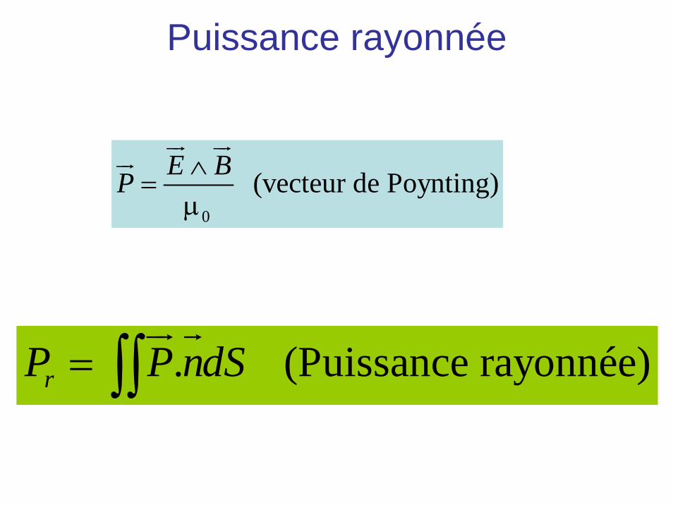
Puissance rayonnée
0
(vecteur de Poynting)E BP ∧=
μ
ur urur
. (Puissance rayonnée)rP P ndS= ∫∫ur r
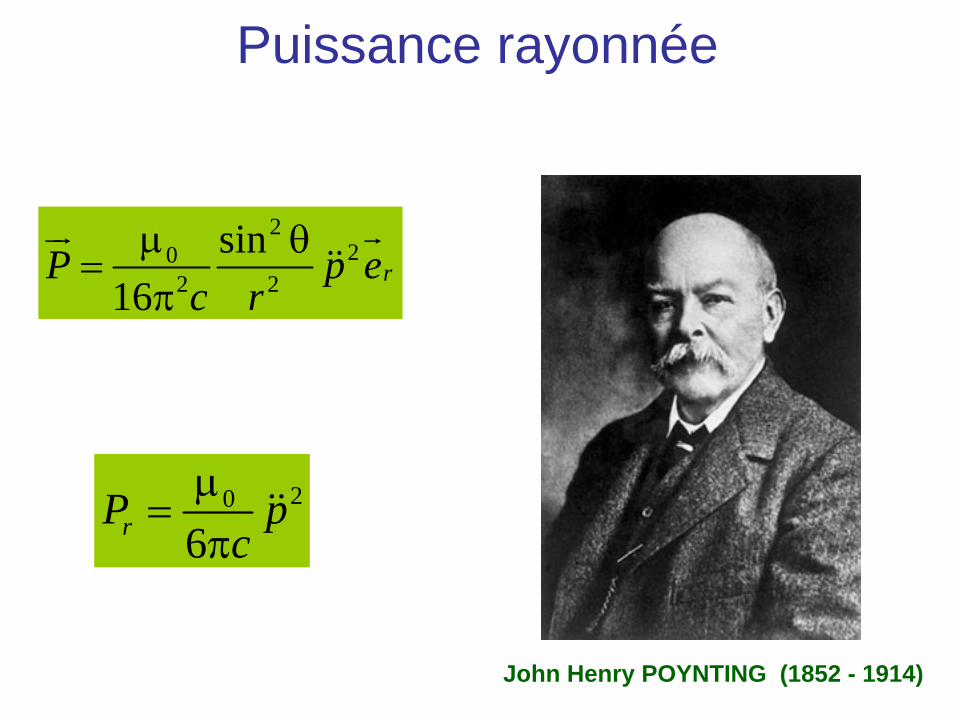
Puissance rayonnée
220
2 2
sin16
rP p ec r
μ θ=
π
ur r&&
20
6rP pc
μ=
π&&
John Henry POYNTING (1852 - 1914)
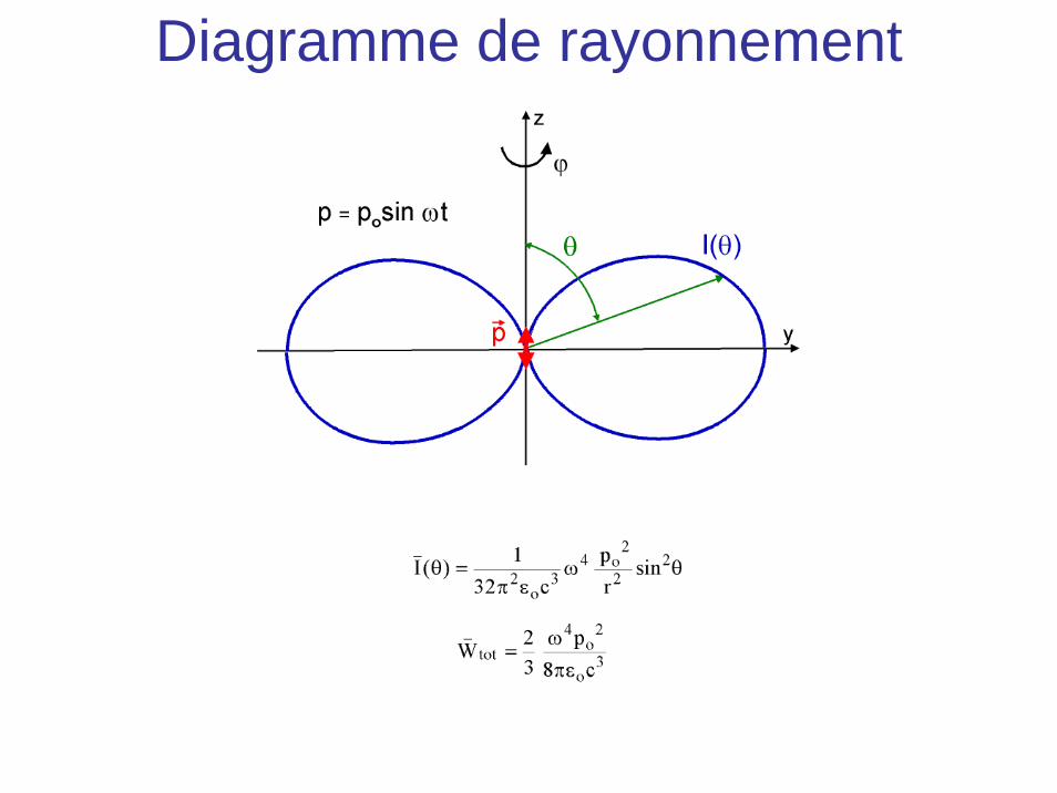
Diagramme de rayonnement
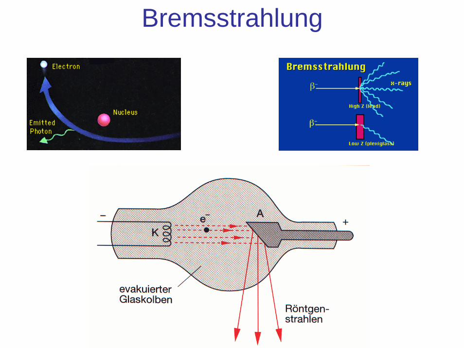
Bremsstrahlung
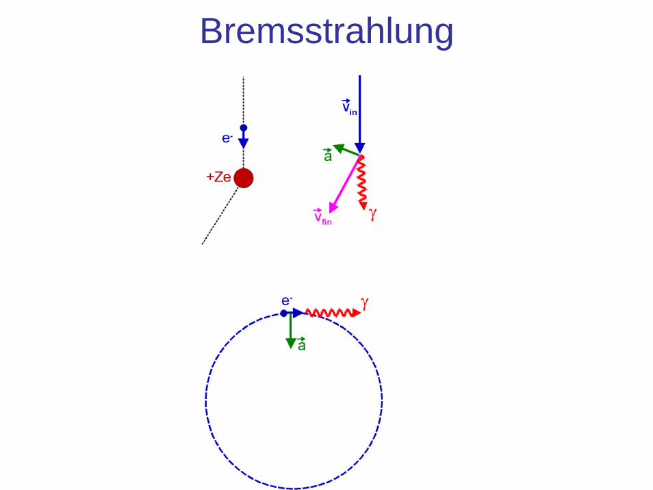
Bremsstrahlung

L’atome de Rutherford (1911)

L’atome de Rutherford (1911)

Difficulté
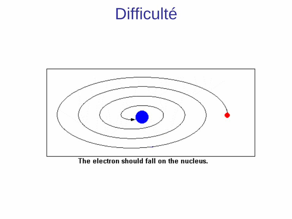
Difficulté
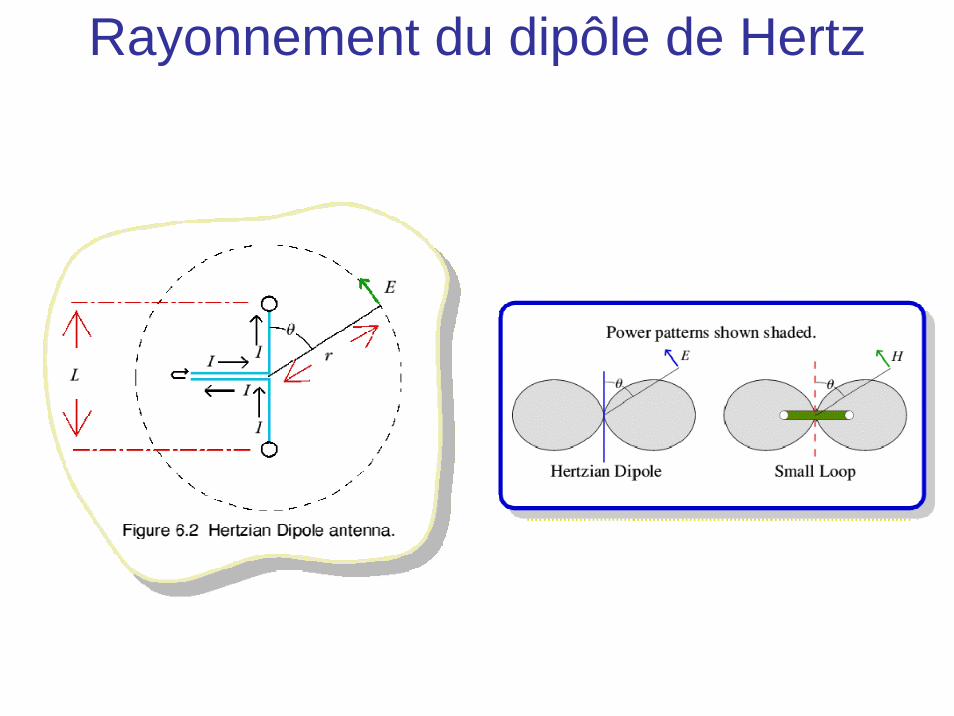
Rayonnement du dipôle de Hertz
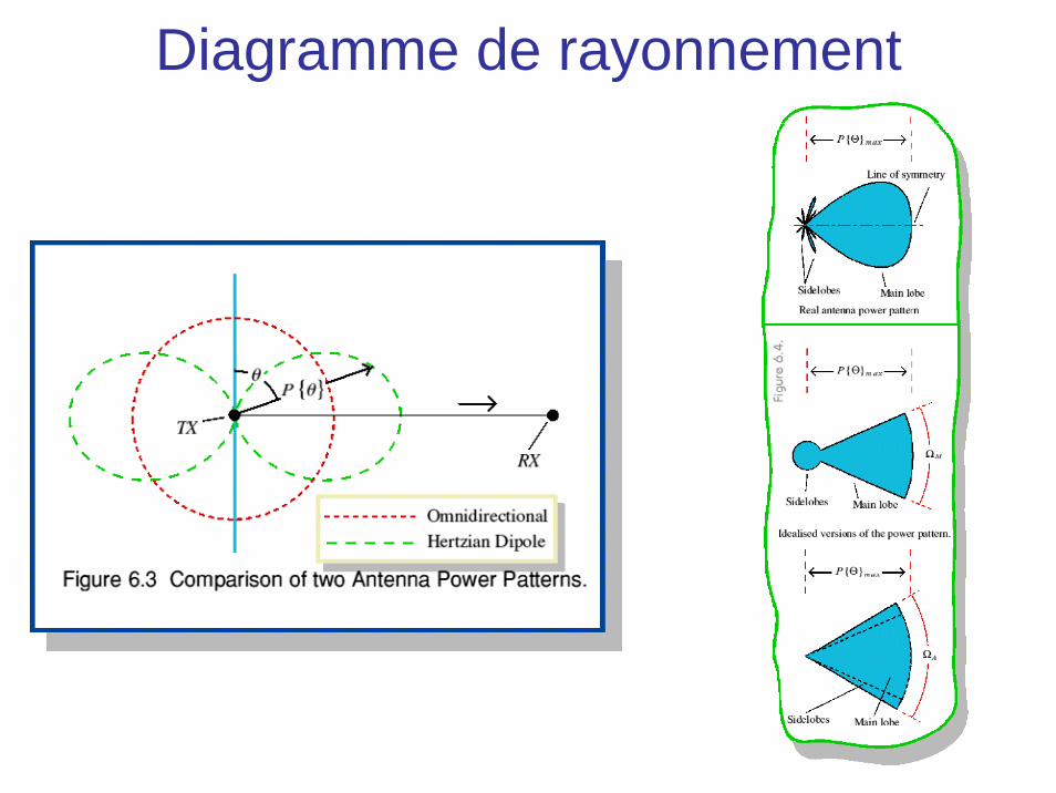
Diagramme de rayonnement
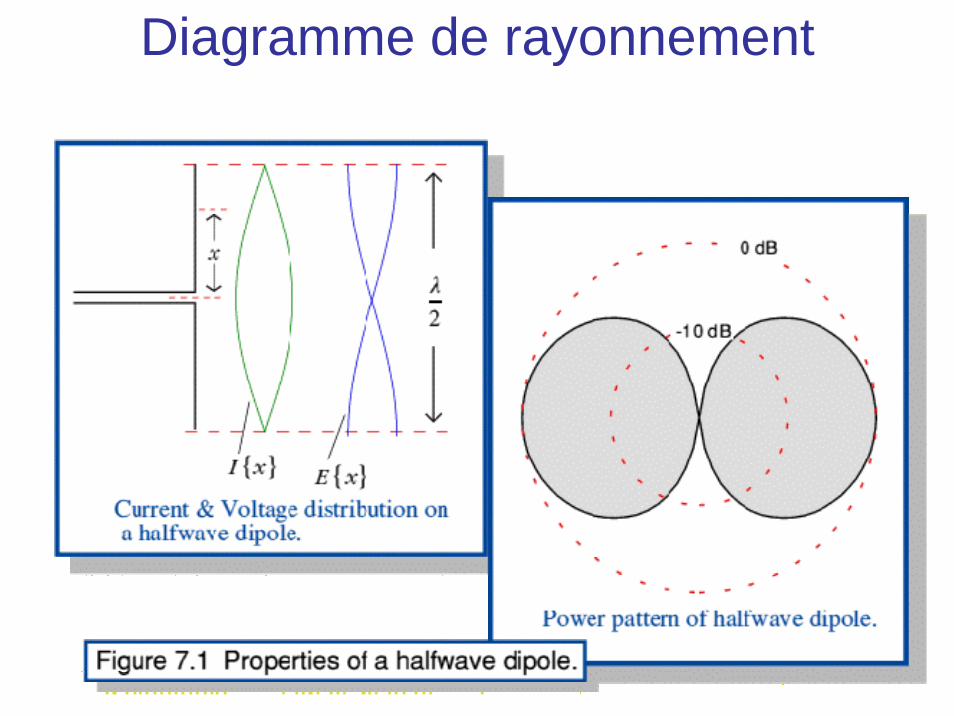
Diagramme de rayonnement

Diagramme de rayonnement

Diagramme de rayonnement
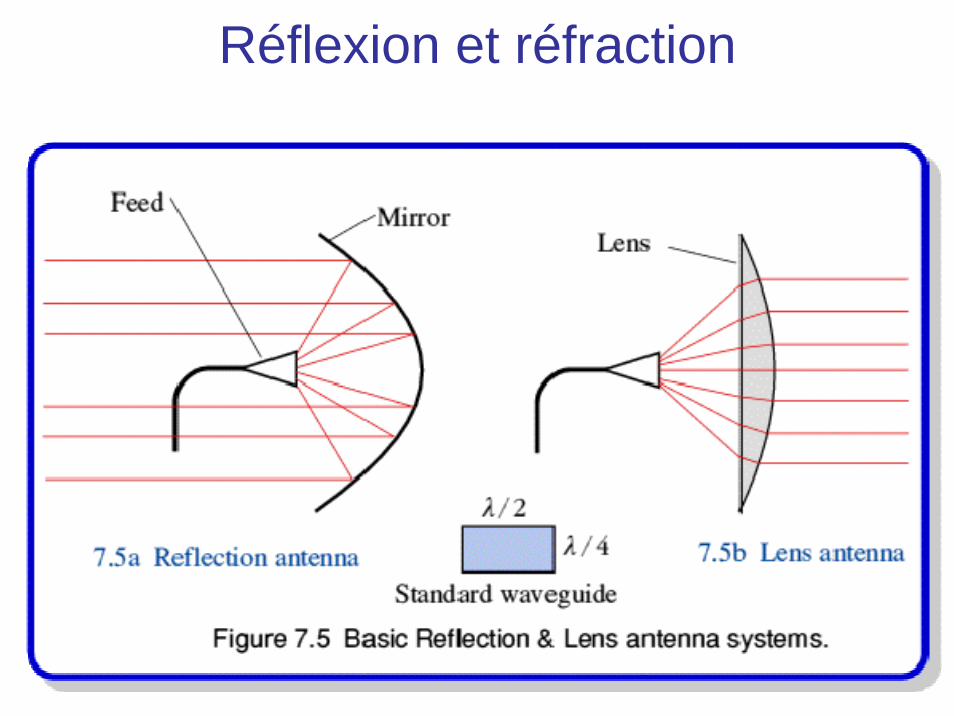
Réflexion et réfraction
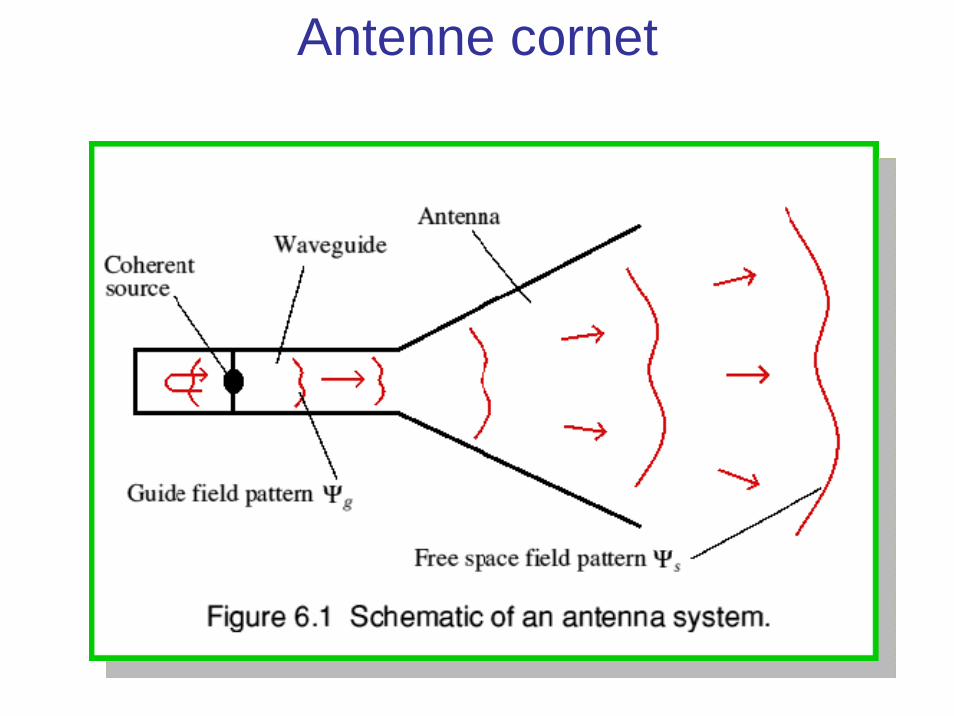
Antenne cornet
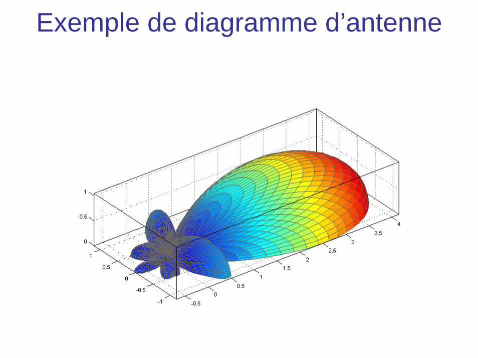
Exemple de diagramme d’antenne

Mesure de diagramme d’antenne


Antenne fouet et antenne cadre

Antennes fouet et boucle
Monopole source = high impedance field = electric field predominanceCapacitive coupling
Loop source = low impedance field = magnetic field predominanceInductive coupling
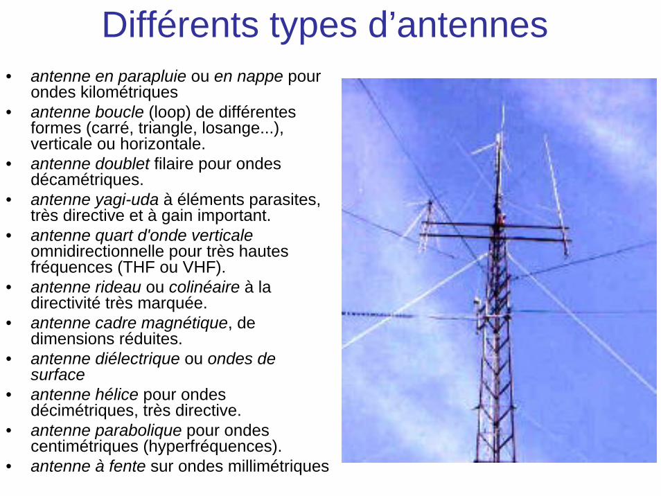
Différents types d’antennes• antenne en parapluie ou en nappe pour
ondes kilométriques • antenne boucle (loop) de différentes
formes (carré, triangle, losange...), verticale ou horizontale.
• antenne doublet filaire pour ondes décamétriques.
• antenne yagi-uda à éléments parasites, très directive et à gain important.
• antenne quart d'onde verticaleomnidirectionnelle pour très hautes fréquences (THF ou VHF).
• antenne rideau ou colinéaire à la directivité très marquée.
• antenne cadre magnétique, de dimensions réduites.
• antenne diélectrique ou ondes de surface
• antenne hélice pour ondes décimétriques, très directive.
• antenne parabolique pour ondes centimétriques (hyperfréquences).
• antenne à fente sur ondes millimétriques
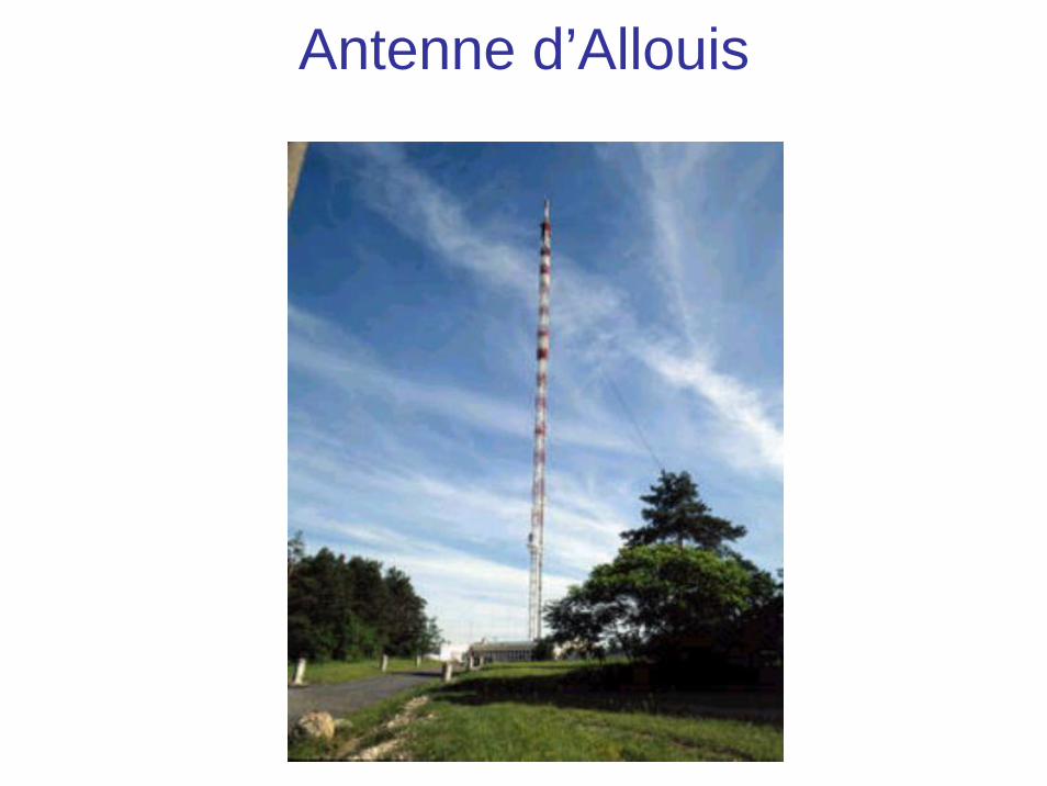
Antenne d’Allouis
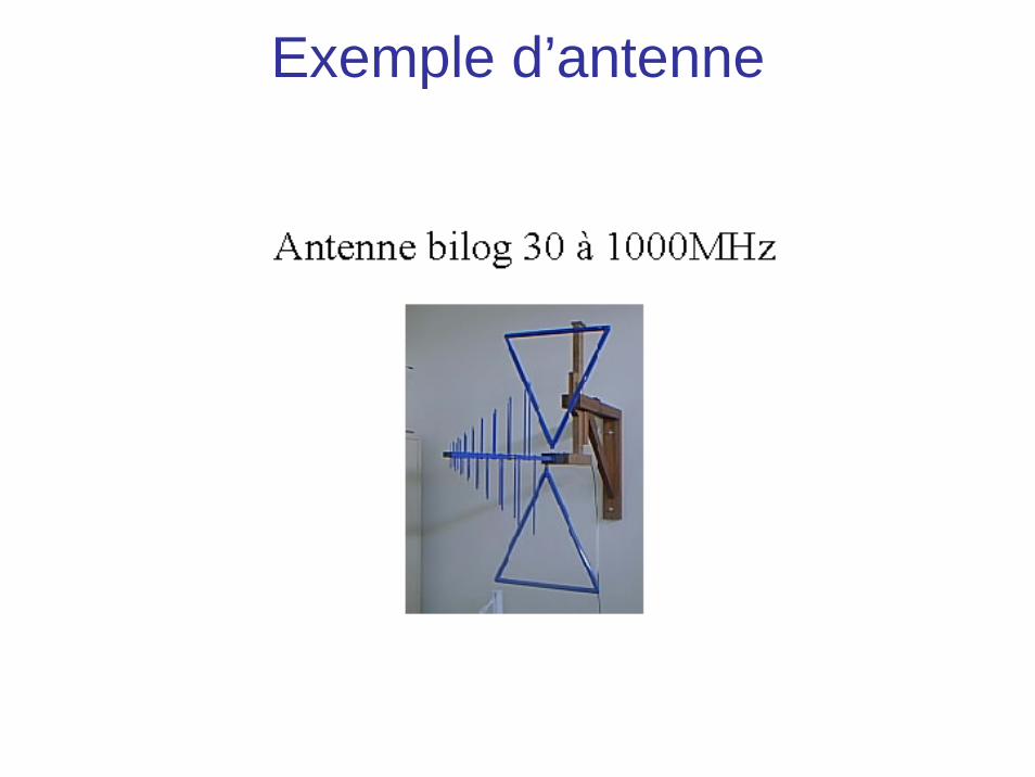
Exemple d’antenne

Exercice : Champ électrique du soleil
L’énergie solaire reçue par 1 cm² de surface terrestre est, dans certaines conditions, de 2 cal.min-1. Calculer dans ces conditions la valeur moyenne, à la surface de la terre, du champ électrique rayonné par le soleil.
Exercice : Portée d’un émetteur
En admettant qu’un récepteur radio est sensible à un champ électrique de 10-3
V/m, déterminer la puissance de l’émetteur nécessaire pour obtenir une portée de 30 km.

Exercice : Diffusion de Rayleigh
Texte sur feuille séparée
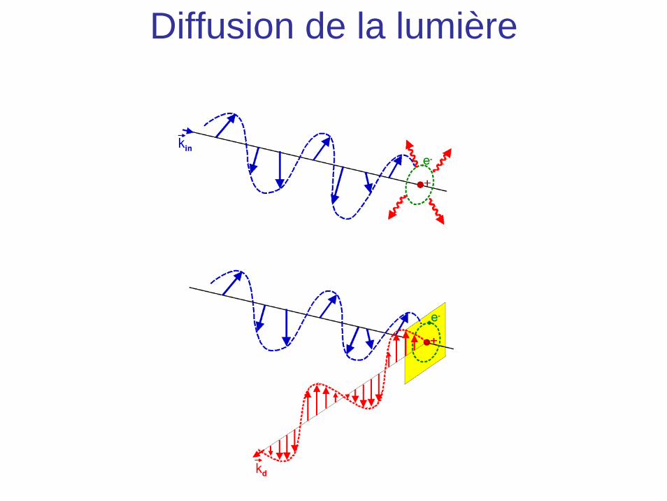
Diffusion de la lumière
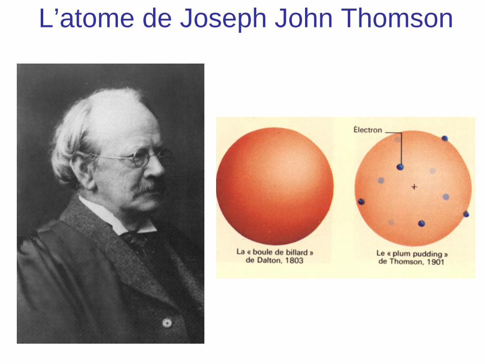
L’atome de Joseph John Thomson

Pourquoi le ciel est bleu
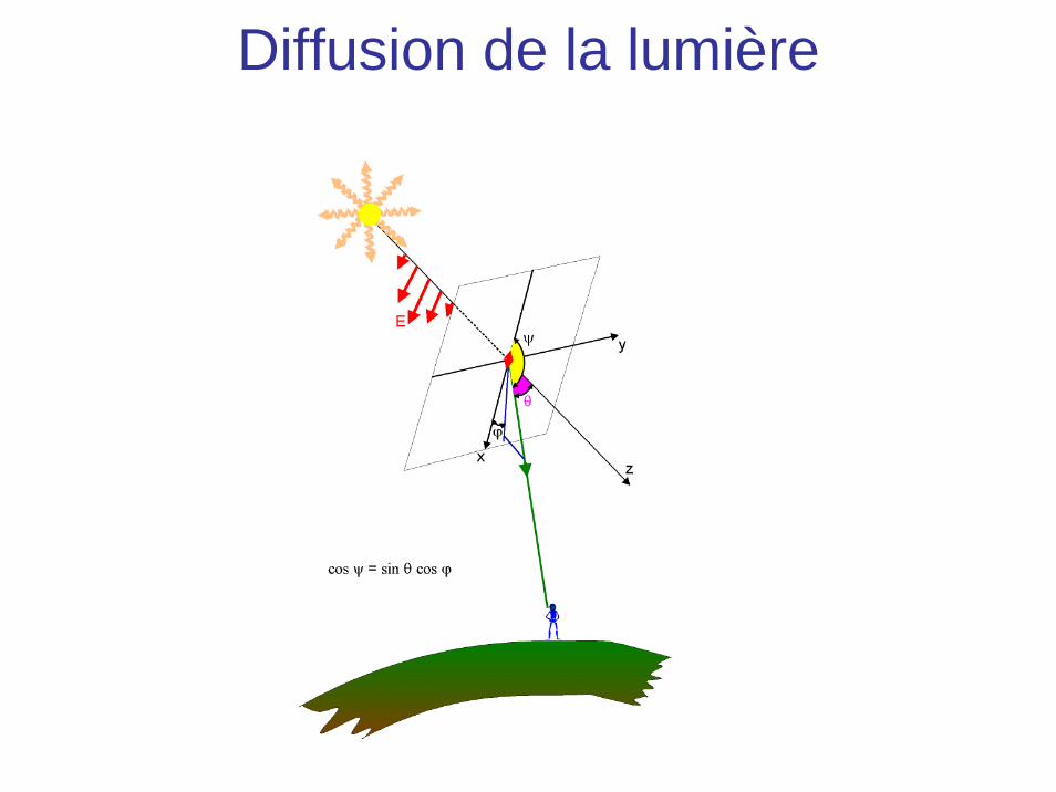
Diffusion de la lumière
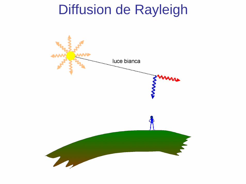
Diffusion de Rayleigh
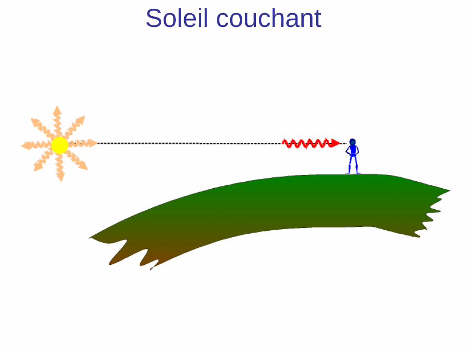
Soleil couchant
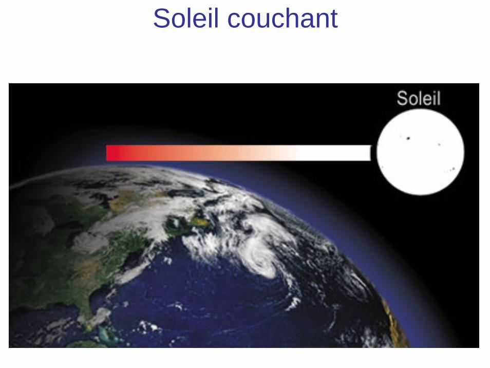
Soleil couchant

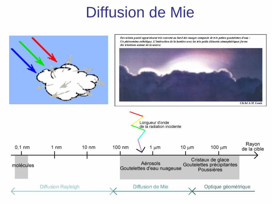
Diffusion de Mie

Exercice : lumière diffusée
Texte sur feuille séparée
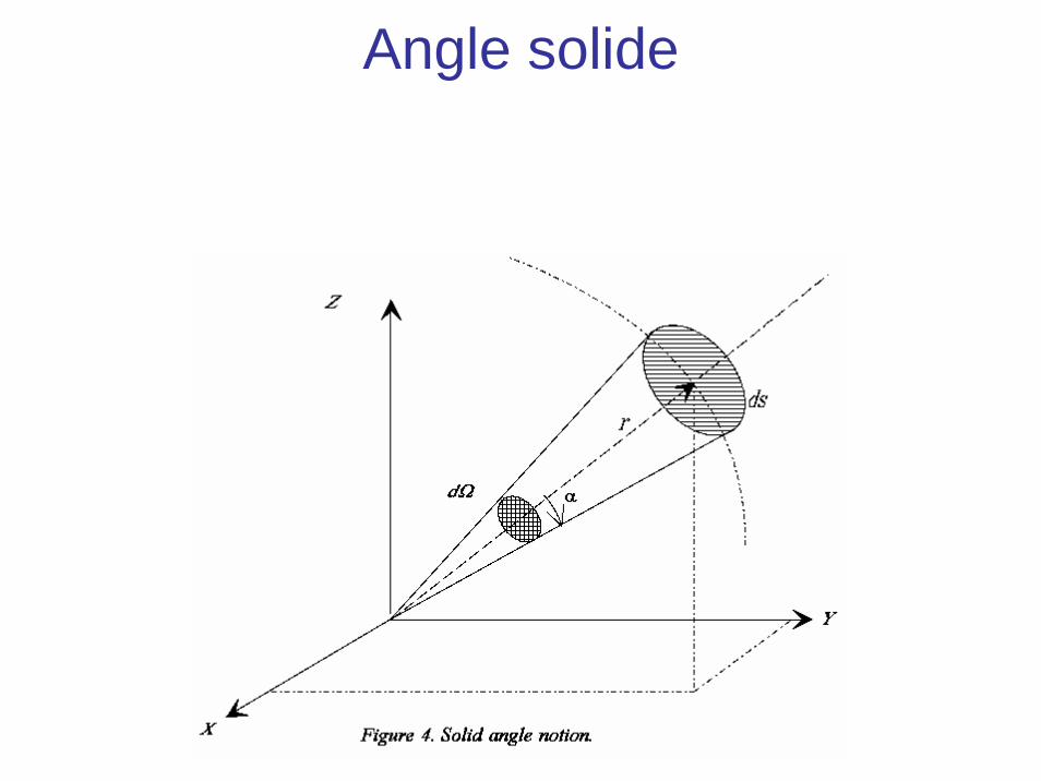
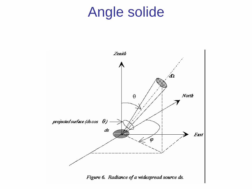
Angle solide
Angle solide
Top Related