


Languages
Pages
Legal

1
Constant-Current LED Drivers with Dual Dimming:Forward/Reverse-Phase and 0 - 10 V
ELM030ELM040ELM050
12-34 W34-40 W41-53 W
ELMSeries
© ERP Power, LLC ELM Series Data SheetRev. May 2017
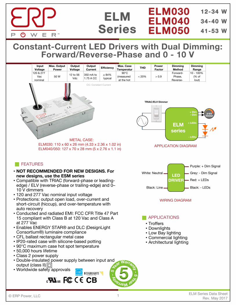
APPLICATION DIAGRAM
APPLICATIONS• Troffers • Downlights• Low Bay lighting• Commercial lighting• Architectural lighting
WIRING DIAGRAM
LEDDRIVER
White: Neutral
Black: Line
Purple: + Dim Signal
Grey: - Dim Signal
Red: + LEDs
Black: - LEDs
CC: Constant Current
METAL CASE:ELM030: 110 x 60 x 26 mm (4.33 x 2.36 x 1.02 in)ELM040/050: 127 x 70 x 28 mm (5 x 2.76 x 1.1 in)
5
Input Voltage
Max. Output Power
Output Voltage
Output Current Efficiency Max. Case
Temperatur THD Power Factor
Dimming Method
Dimming Range
120 & 277 Vac
nominal50 W 12 to 56
Vdc350 mA to 1.75 A CC
≥ 84% typical
90°C (measured at the hot
< 20% > 0.9Forward-Phase,
Reverse-
10 - 100%(% of Iout)
FEATURES• NOT RECOMMENDED FOR NEW DESIGNS. For
new designs, use the ESM series• Compatible with TRIAC (forward-phase or leading-
edge) / ELV (reverse-phase or trailing-edge) and 0–10 V dimmers• 120 and 277 Vac nominal input voltage• Protections: output open load, over-current and
short-circuit (hiccup), and over-temperature with auto recovery• Conducted and radiated EMI: FCC CFR Title 47 Part
15 compliant with Class B at 120 Vac and Class A at 277 Vac• Enables ENERGY STAR® and DLC (DesignLight
Consortium®) luminaire compliance• CFL ballast rectangular metal case• IP20-rated case with silicone-based potting• 90°C maximum case hot spot temperature• 50,000 hours lifetime• Class 2 power supply• Double-insulated power supply between input and
output (class II)• Worldwide safety approvals
ELMseries
+ LEDs
- LEDs
+ Dim- Dim 0-10 V
Dimmer
TRIAC/ELV Dimmer
2
Constant-Current LED Drivers with Dual Dimming:Forward/Reverse-Phase and 0 - 10 V
ELM030ELM040ELM050
12-34 W34-40 W41-53 W
ELMSeries
[email protected] www.erp-power.com
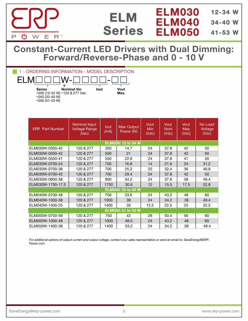
1 - ORDERING INFORMATION - MODEL DESCRIPTION
ELM☐☐☐W-☐☐☐☐-☐☐Nominal Vin•120 & 277 Vac
Iout VoutMax.
Series•030 (12-34 W)•040 (33-40 W)•050 (41-53 W)
For additional options of output current and output voltage, contact your sales representative or send an email to: [email protected]
ERP Part NumberNominal Input Voltage Range
(Vac)Iout (mA)
Max Output Power (W)
VoutMin(Vdc)
VoutNom(Vdc)
VoutMax(Vdc)
No Load Voltage (Vdc)
ELM030W-0350-42 120 & 277 350 14.7 24 37.8 42 50ELM030W-0500-42 120 & 277 500 21 24 37.8 42 50ELM030W-0550-41 120 & 277 550 22.6 24 37.8 41 50ELM030W-0700-24 120 & 277 700 16.8 14 21.6 24 31.2ELM030W-0700-36 120 & 277 700 25.2 22 32.4 36 46.8ELM030W-0700-42 120 & 277 700 29.4 24 37.8 42 50ELM030W-0900-38 120 & 277 900 34.2 24 37.8 38 49.4ELM030W-1750-17.5 120 & 277 1750 30.6 12 15.5 17.5 22.8
ELM040W-0700-48 120 & 277 700 33.6 24 43.2 48 60ELM040W-1000-38 120 & 277 1000 38 24 34.2 38 49.4ELM040W-1400-25 120 & 277 1400 35 12.5 22.5 25 32.5
ELM050W-0750-56 120 & 277 750 42 28 50.4 56 60ELM050W-1000-48 120 & 277 1000 48.0 24 43.2 48 60ELM050W-1400-38 120 & 277 1400 53.2 24 34.2 38 49.4
ELM040: 33 to 40 W
ELM050: 41 to 53 W
ELM030: 12 to 34 W
3
Constant-Current LED Drivers with Dual Dimming:Forward/Reverse-Phase and 0 - 10 V
ELM030ELM040ELM050
12-34 W34-40 W41-53 W
ELMSeries
[email protected] www.erp-power.com
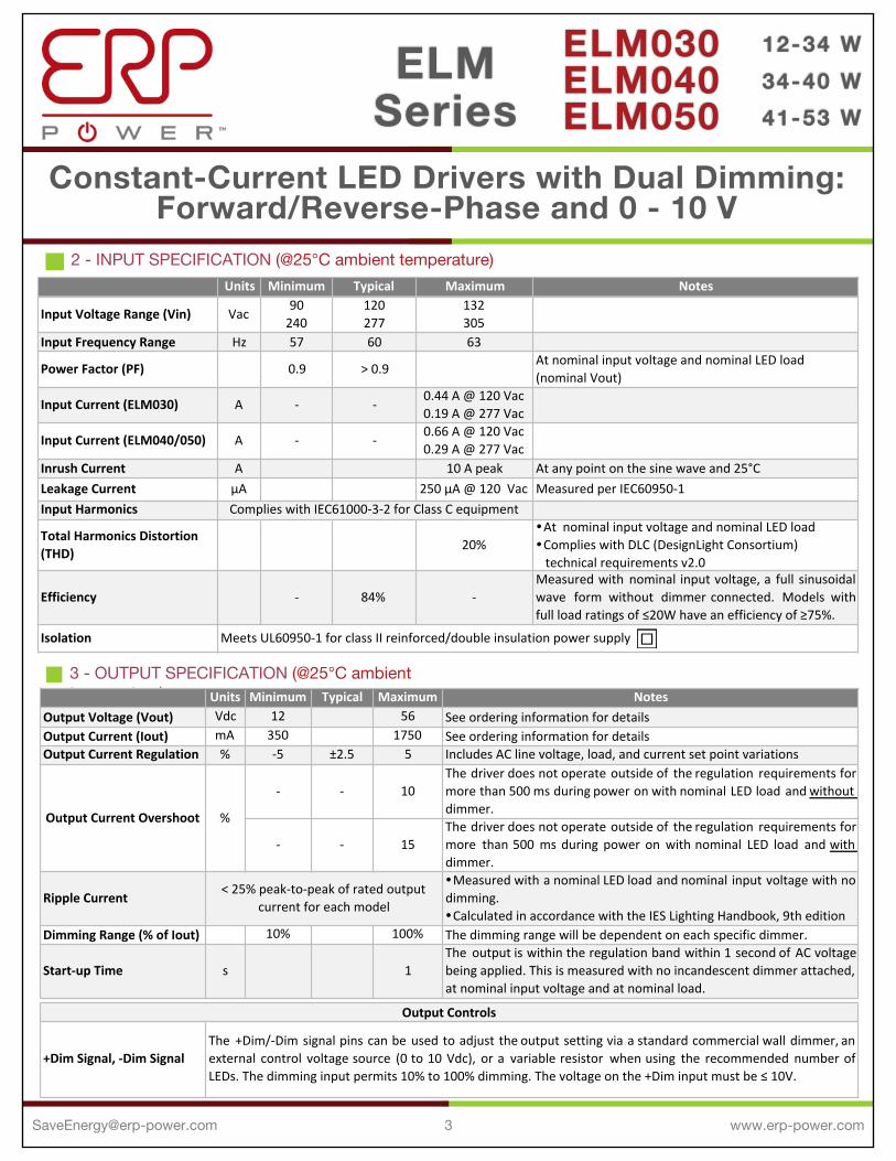
Units Minimum Typical Maximum Notes
Input4Voltage4Range4(Vin) Vac90240
120277
132305
Input4Frequency4Range Hz 57 60 63
Power4Factor4(PF) 0.9 >10.9At1nominal1input1voltage1and1nominal1LED1load1(nominal1Vout)
Input4Current4(ELM030) A D [email protected]@12771Vac
Input4Current4(ELM040/050) A D [email protected]@12771Vac
Inrush4Current A 101A1peak At1any1point1on1the1sine1wave1and125°CLeakage4Current μA 2501μA1@112011Vac Measured1per1IEC60950D1Input4Harmonics
Total4Harmonics4Distortion4(THD) 20%
!At11nominal1input1voltage1and1nominal1LED1load!Complies1with1DLC1(DesignLight1Consortium)1111technical1requirements1v2.0
Efficiency D 84% DMeasured with nominal input voltage, a full sinusoidalwave form without dimmer connected. Models withfull1load1ratings1of1≤20W1have1an1efficiency1of1≥75%.
Isolation
Complies1with1IEC61000D3D21for1Class1C1equipment
Meets1UL60950D11for1class1II1reinforced/double1insulation1power1supply
2 - INPUT SPECIFICATION (@25°C ambient temperature)
3 - OUTPUT SPECIFICATION (@25°C ambient temperature) Units Minimum Typical Maximum Notes
Output4Voltage4(Vout) Vdc 12 56 See*ordering*information*for*detailsOutput4Current4(Iout) mA 350 1750 See*ordering*information*for*detailsOutput4Current4Regulation % ;5 ±2.5 5 Includes*AC*line*voltage,*load,*and*current*set*point*variations
; ; 10The driver does not operate outside of the regulation requirements formore than 500 ms during power on with nominal LED load and without*dimmer.
; ; 15The driver does not operate outside of the regulation requirements formore than 500 ms during power on with nominal LED load and with*dimmer.
Ripple4Current!Measured with a nominal LED load and nominal input voltage with nodimming.!Calculated*in*accordance*with*the*IES*Lighting*Handbook,*9th*edition
Dimming4Range4(%4of4Iout) 10% 100% The*dimming*range*will*be*dependent*on*each*specific*dimmer.
StartAup4Time s 1The output is within the regulation band within 1 second of AC voltagebeing*applied.*This*is*measured*with*no*incandescent*dimmer*attached,*at*nominal*input*voltage*and*at*nominal*load.
+Dim4Signal,4ADim4Signal
<*25%*peak;to;peak*of*rated*output*current*for*each*model
Output4Controls
The +Dim/;Dim signal pins can be used to adjust the output setting via a standard commercial wall dimmer, anexternal control voltage source (0 to 10 Vdc), or a variable resistor when using the recommended number ofLEDs.*The*dimming*input*permits*10%*to*100%*dimming.*The*voltage*on*the*+Dim*input*must*be*≤*10V.
Output4Current4Overshoot %

4
Constant-Current LED Drivers with Dual Dimming:Forward/Reverse-Phase and 0 - 10 V
ELM030ELM040ELM050
12-34 W34-40 W41-53 W
ELMSeries
[email protected] www.erp-power.com
6 - EMC COMPLIANCE AND SAFETY APPROVALS
Conducted)and)Radiated)EMIHarmonic)Current)Emissions IEC61000'3'2 For-Class-C-equipmentVoltage)Fluctuations)&)Flicker IEC61000'3'3
ESD)(Electrostatic)Discharge)
IEC61000'4'2 6-kV-contact-discharge,-8-kV-air-discharge,-level-3
RF)Electromagnetic)Field)Susceptibility
IEC61000'4'3 3V/m,-80-'-1000-MHz,-80%-modulated-at-distance-of-3-meters
Electrical)Fast)Transient IEC61000'4'4 ±-2-kV-on-AC-power-port-for-1-minute,-±1-kV-on-signal/control-lines
Surge IEC61000'4'5 ±-1-kV-line-to-line-(differential-mode)-/±-2-kV-line-to-common-mode-ground-(tested-to-secondary-ground)-on-AC-power-port,-±0.5-kV-for-outdoor-cables
Conducted)RF)Disturbances
IEC61000'4'6 3-V,-0.15'80-MHz,-80%-modulated
Voltage)Dips IEC61000'4'11 >95%-dip,-0.5-period;-30%-dip,-25-periods;-95%-reduction,-250-periodsTransient)Protection Ring)Wave ANSI/IEEE-c62.41.1'2002-&-c62.41.2'2002-category-A,-2.5-kV-ring-wave
UL UL8750-recognized -UL60950'1-recognizedcULCE IEC61347'2'13-electronic-control-gear-for-LED-Modules
ENEC-mark-and-CE-mark-for-EU
EMC)ComplianceFCC-CFR-Title-47-Part-15-Class-B-at-120-Vac-and-Class-A-at-277-Vac
Immunity)Compliance
Safety)Agency)Approvals
CSA-C22.2-60950'1
Units Minimum Typical Maximum Notes
Hi4Pot4(High4Potential) Vdc 4242!Insulation/between/the/input/(AC/line/and/Neutral)/and/the/output!Tested/at/the/RMS/voltage/equivalent/of/3000/Vac
Safety
4 - PROTECTION FEATURESOutput Open Load, Over-Current and Short-Circuit Protection (hiccup), and Over-TemperatureProtection with Auto Recovery
5 - ENVIRONMENTAL CONDITIONS Units Minimum Typical Maximum Notes
Operating6Case6Temperature6(Tc) °C #30 +90Case+temperature+measured+at+the+hot+spot+!tc+
on+label.+See+labeling+in+page+9.
Storage6Temperature °C #40 +85
Humidity % 5 # 95 Non#condensing
Cooling
Acoustic6Noise dBA 24Measured+at+a+distance+of+1+meter,+without+and+
with+approved+dimmers.
Mechanical6Shock6Protection per+EN60068#2#27
Vibration6Protection per+EN60068#2#6+&+EN60068#2#64
MTBF >+250,000+hours+when+operated+at+nominal+input+and+output+conditions,+and+at+Tc+≤+70°C
Lifetime 50,000+hours+at+70°C+maximum+case+hot+spot+temperature+(see+hot+spot+!tc+on+label+in+page+9)
Convection+cooled
5
Constant-Current LED Drivers with Dual Dimming:Forward/Reverse-Phase and 0 - 10 V
ELM030ELM040ELM050
12-34 W34-40 W41-53 W
ELMSeries
[email protected] www.erp-power.com
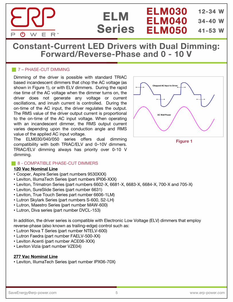
7 – PHASE-CUT DIMMINGDimming of the driver is possible with standard TRIACbased incandescent dimmers that chop the AC voltage (asshown in Figure 1), or with ELV dimmers. During the rapidrise time of the AC voltage when the dimmer turns on, thedriver does not generate any voltage or currentoscillations, and inrush current is controlled. During theon-time of the AC input, the driver regulates the output.The RMS value of the driver output current is proportionalto the on-time of the AC input voltage. When operatingwith an incandescent dimmer, the RMS output currentvaries depending upon the conduction angle and RMSvalue of the applied AC input voltage.The ELM030/040/050 series offers dual dimmingcompatibility with both TRIAC/ELV and 0–10V dimmers.TRIAC/ELV dimming always has priority over 0-10 Vdimming.
120 Vac Nominal Line• Cooper, Aspire Series (part numbers 9530XXX)• Leviton, IllumaTech Series (part numbers IPI06-XXX)• Leviton, Trimatron Series (part numbers 6602-X, 6681-X, 6683-X, 6684-X, 700-X and 705-X)• Leviton, SureSlide Series (part number 6631)• Leviton, True Touch Series part number 6606-1LM)• Lutron Skylark Series (part numbers S-600, S2-LH)• Lutron, Maestro Series (part number MAW-600)• Lutron, Diva series (part number DVCL-153)
In addition, the driver series is compatible with Electronic Low Voltage (ELV) dimmers that employ reverse-phase (also known as trailing-edge) control such as:• Lutron Nova T Series (part number NTELV-600)• Lutron Faedra (part number FAELV-500-XX)• Leviton Acenti (part number ACE06-XXX)• Leviton Vizia (part number VZE04)
277 Vac Nominal Line• Leviton, IllumaTech Series (part number IPX06-70X)
8 - COMPATIBLE PHASE-CUT DIMMERS
Figure 1

6
Constant-Current LED Drivers with Dual Dimming:Forward/Reverse-Phase and 0 - 10 V
ELM030ELM040ELM050
12-34 W34-40 W41-53 W
ELMSeries
[email protected] www.erp-power.com
9 - 0-10 V DIMMING
• Lutron, Nova Series (part number NFTV)10 - COMPATIBLE 0-10 V DIMMERS
The ELM drivers operate only with 0-10V dimmers that sink current. They are not designed to operate with 0-10Vcontrol systems that source current, as used in theatrical/entertainment systems. Developed in the 1980’s, the 0-10Vsinking current control method is adopted by the International Electrotechnical Commission (IEC) as apart of their IECStandard 60929 Annex E.This method to dim the driver’s output current is done via the +Dim/-Dim signal pins. These signal pins respond to a 1to 10 V signal, delivering 10% to 100% of the output current based on rated current for each model. A pull-up resistoris included internal to the driver. When the +Dim input is short circuited to the –Dim wire or to the –LED wire, theoutput current is programmed to ≤ 5% of rated current. If the +Dim input is open circuited, the output current isprogrammed to 100% of rated current.When not used, the –Dim wire (grey) and to the +Dim wire (purple) can be capped or cut off. In this configuration, nodimming is possible and the driver delivers 100% of its rated output current. The voltage on the +Dim input must be ≤10V.A fixed or variable resistor can be also used from the dimming input to the return to adjust the output current. Figure 2and 3 show the relationship of the output current to a resistor connected across the 0-10V dimming input, for theELM030 and the ELM040/050 series.
The maximum current supplied by the +Dimsignal pin is ≤ 2.5 mA. The tolerance of theoutput current while being dimmed is +/-5% typical until down to 2V.Figure 4 shows the relationship of theoutput current to the dimming inputvoltage.
Figure 2
0% 10% 20% 30% 40% 50% 60% 70% 80% 90%
100%
0 2000 4000 6000 8000 10000 12000
ELM030Series
Perc
ent o
f Out
put C
urre
nt(N
orm
aliz
ed to
Rat
ed C
urre
nt)
Resistance (Ω)
0% 10% 20% 30% 40% 50% 60% 70% 80% 90%
100%
0 2000 4000 6000 8000 10000 12000
ELM040/50Series
Resistance (Ω)
Perc
ent o
f Out
put C
urre
nt(N
orm
aliz
ed to
Rat
ed C
urre
nt)
Figure 3
0% 10% 20% 30% 40% 50% 60% 70% 80% 90%
100% 110%
0 1 2 3 4 5 6 7 8 9 10
NormalizedOutputCurrentvs DimmingVoltage
Dimming Voltage(V)
Perc
ent o
f Out
put C
urre
nt(N
orm
aliz
ed to
Rat
ed C
urre
nt
Figure 4
7
Constant-Current LED Drivers with Dual Dimming:Forward/Reverse-Phase and 0 - 10 V
ELM030ELM040ELM050
12-34 W34-40 W41-53 W
ELMSeries
[email protected] www.erp-power.com
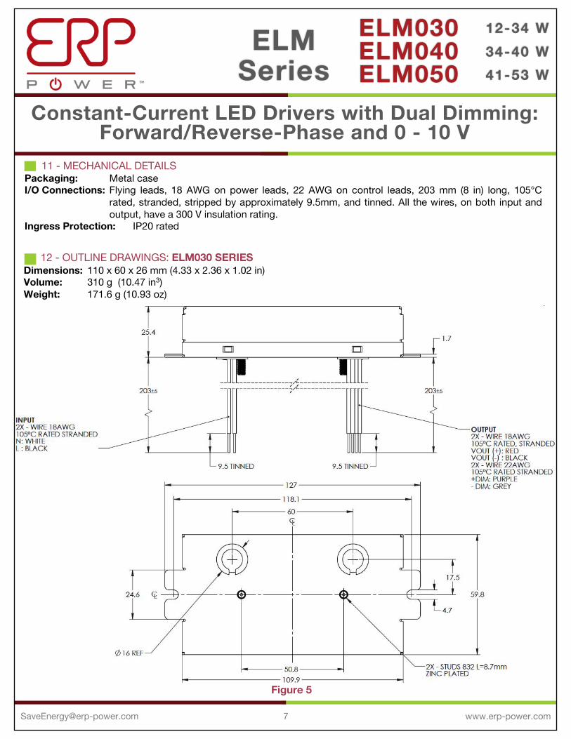
11 - MECHANICAL DETAILSPackaging: Metal caseI/O Connections: Flying leads, 18 AWG on power leads, 22 AWG on control leads, 203 mm (8 in) long, 105°C
rated, stranded, stripped by approximately 9.5mm, and tinned. All the wires, on both input andoutput, have a 300 V insulation rating.
Ingress Protection: IP20 rated
12 - OUTLINE DRAWINGS: ELM030 SERIESDimensions: 110 x 60 x 26 mm (4.33 x 2.36 x 1.02 in)Volume: 310 g (10.47 in3)Weight: 171.6 g (10.93 oz)
Figure 5
8
Constant-Current LED Drivers with Dual Dimming:Forward/Reverse-Phase and 0 - 10 V
ELM030ELM040ELM050
12-34 W34-40 W41-53 W
ELMSeries
[email protected] www.erp-power.com
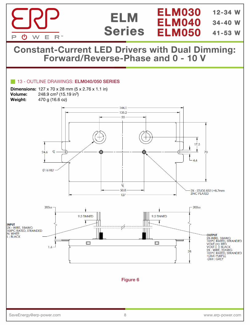
13 - OUTLINE DRAWINGS: ELM040/050 SERIESDimensions: 127 x 70 x 28 mm (5 x 2.76 x 1.1 in)Volume: 248.9 cm3 (15.19 in3)Weight: 470 g (16.6 oz)
Figure 6

9
Constant-Current LED Drivers with Dual Dimming:Forward/Reverse-Phase and 0 - 10 V
ELM030ELM040ELM050
12-34 W34-40 W41-53 W
ELMSeries
[email protected] www.erp-power.com
14 - LABELINGThere are two labels on the case of each model in the ELM030/040/050 series: one on the top face and one on the bottom face (face from where the wires exit).The ELM030W-0500-42 is used as an example to illustrate the typical labels.
Figure 7
Top Face
Bottom Face
ERP Power, LLC (ERP) reserves the right to make changes without further notice to any products herein. ERP makes no warranty, representation or guaranteeregarding the suitability of its products for any particular purpose, nor does ERP assume any liability arising out of the application or use of any product orcircuit, and specifically disclaims any and all liability, including without limitation special, consequential or incidental damages. “Typical” parameters whichmay be provided in ERP data sheets and/or specifications can and do vary in different applications and actual performance may vary over time. All operatingparameters, including “Typicals” must be validated for each customer application by customer’s technical experts. ERP does not convey any license under itspatent rights nor the rights of others. ERP products are not designed, intended, or authorized for use as components in systems intended for surgical implantinto the body, or other applications intended to support or sustain life, or for any other application in which the failure of the ERP product could create asituation where personal injury or death may occur. Should Buyer purchase or use ERP products for any such unintended or unauthorized application, Buyershall indemnify and hold ERP and its officers, employees, subsidiaries, affiliates, and distributors harmless against all claims, costs, damages, and expenses,and reasonable attorney fees arising out of, directly or indirectly, any claim of personal injury or death associated with such unintended or unauthorized use,even if such claim alleges that ERP was negligent regarding the design or manufacture of the part. ERP is an Equal Opportunity/Affirmative Action Employer.This literature is subject to all applicable copyright laws and is not for resale in any manner.
CHINA OperationsTel: +86-756-6266298Fax: +86-756-6266299No. 8 Pingdong Road 2Zhuhai, Guangdong, China 519060
USA Headquarters Tel: +1-805-517-1300Fax: +1-805-517-1411893 Patriot Drive, Suite E,Moorpark, CA 93021, USA
Top Related