


Languages
Pages
Legal

Electronic InstrumentationExperiment 5
* AC Steady State Theory
* Part A: RC and RL Circuits
* Part B: RLC Circuits

AC Steady State Theory
Transfer Functions Phasors Complex Impedance Complex Transfer Functions

Transfer Functions
The transfer function describes the behavior of a circuit at Vout for all possible Vin.
in
out
V
VH

Simple Example
321
32*
RRR
RRVV inout
KKK
KKVV inout 321
32*
6
5
in
out
V
VH
VKtVtVthen
VKtVtVif
out
in
10)2
2sin(5)(
12)2
2sin(6)(

More Complicated Example
What is H now?
H now depends upon the input frequency ( = 2f) because the capacitor and inductor make the voltages change with the change in current.

Influence of Resistor on Circuit
Resistor modifies the amplitude of the signal by R
Resistor has no effect on the phase
RIV RR
)2
cos(*)sin(*)(
)2
cos()sin()(
tARtARtVthen
tAtAtIif
R
R
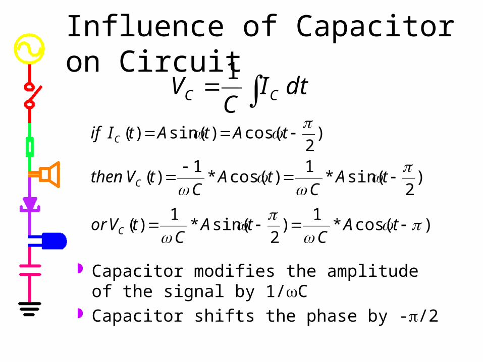
Influence of Capacitor on Circuit
Capacitor modifies the amplitude of the signal by 1/C
Capacitor shifts the phase by -/2
dtIC
V CC
1
)cos(*1
)2
sin(*1
)(
)2
sin(*1
)cos(*1
)(
)2
cos()sin()(
tAC
tAC
tVor
tAC
tAC
tVthen
tAtAtIif
C
C
C

Influence of Inductor on Circuit
Inductor modifies the amplitude of the signal by L
Inductor shifts the phase by +/2
dt
dILV L
L
)cos(*)2
sin(*)(
)2
sin(*)cos(*)(
)2
cos()sin()(
tALtALtVor
tALtALtVthen
tAtAtIif
L
L
L

How do we model H? We want a way to combine the effect of
the components in terms of their influence on the amplitude and the phase.
We can only do this because the signals are sinusoids• cycle in time• derivatives and integrals are just phase
shifts and amplitude changes

Phasors
Phasors allow us to manipulate sinusoids in terms of amplitude and phase changes
Phasors are based on complex polar coordinates
The influence of each component is given by Z, its complex impedance
ZIV
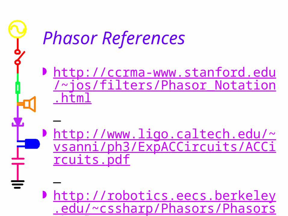
Phasor References
http://ccrma-www.stanford.edu/~jos/filters/Phasor_Notation.html
http://www.ligo.caltech.edu/~vsanni/ph3/ExpACCircuits/ACCircuits.pdf
http://robotics.eecs.berkeley.edu/~cssharp/Phasors/Phasors.html

Phasor Applet
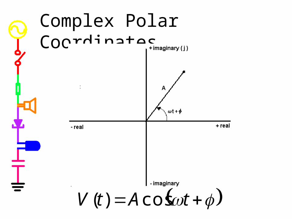
Complex Polar Coordinates
tAtV cos)(

Review of Polar Coordinates
point P is at( rpcosp , rpsinp )
22
1tan
PPP
P
PP
yxr
x
y

Introduction to Complex Numbers
zp is a single number represented by two numbers
zp has a “real” part (xp) and an “imaginary” part (yp)
jj
jj
j
1
1
1

Now we can define Phasors
)sin()cos(
,)cos()(
tjAtAV
letthentAtVif
The real part is our signal. The two parts allow us to determine the
influence of the phase and amplitude changes mathematically.
After we manipulate the numbers, we discard the imaginary part.

Magnitude and Phase
Vofphasetx
yV
VofmagnitudeAyxV
jyxtAjtAV
1
22
tan
)sin()cos(
Phasors have a magnitude and a phase derived from polar coordinates rules.

Euler’s Formula
sincos je j
2132
13
)(
2
1
2
1
2
13
,
sincos
21
2
1
andr
rrtherefore
er
r
er
er
z
zz
rejrrjyxz
jj
j
j

Manipulating Phasors (1)
2132
13
)(
2
1
2
1)(
2
)(1
2
13
)(
,
)sin()cos(
21
2
1
2
1
VandA
AVtherefore
eA
A
e
e
e
e
A
A
eA
eA
V
VV
AetjtAV
jj
tj
tj
tj
tj
tj
Note t is eliminated by the ratio• This gives the phase change between
signal 1 and signal 2

Manipulating Phasors (2)
22
22
21
2
2
1
3
1
yx
yx
V
VV
333
222111
jyxV
jyxVjyxV
2
21
1
11213 tantan
x
y
x
yVVV
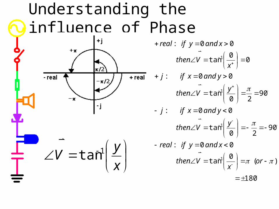
Understanding the influence of Phase
x
yV 1tan
180
)(0
tan
00:
9020
tan
00:
9020
tan
00:
00
tan
00:
1
1
1
1
orx
Vthen
xandyifreal
yVthen
yandxifj
yVthen
yandxifj
xVthen
xandyifreal

Complex Impedance
Z defines the influence of a component on the amplitude and phase of a circuit• Resistors: ZR = R
• change the amplitude by R
• Capacitors: ZC=1/jC • change the amplitude by 1/C
• shift the phase -90 (1/j=-j)
• Inductors: ZL=jL • change the amplitude by L
• shift the phase +90 (j)
ZIV

Capacitor Impedance Proof
)(1
)()()(
)(
)()cos()(
Re)(
)()(
)sin()cos()(
)cos()()(
)(
)()(
)(
tICj
tVtVCjdt
tdVCtI
tVjtAjdt
jVd
dt
tdV
jVjeAjdt
dAe
dt
jVd
AetjAtAjV
tAtVanddt
tdVCtI
CCCC
C
CCC
Ctj
tjC
tjC
CC
C
CjZC
1Prove:

Complex Transfer Functions
If we use phasors, we can define H for all circuits in this way.
If we use complex impedances, we can combine all components the way we combine resistors.
H and V are now functions of j and
)(
)()(
jV
jVjH
in
out
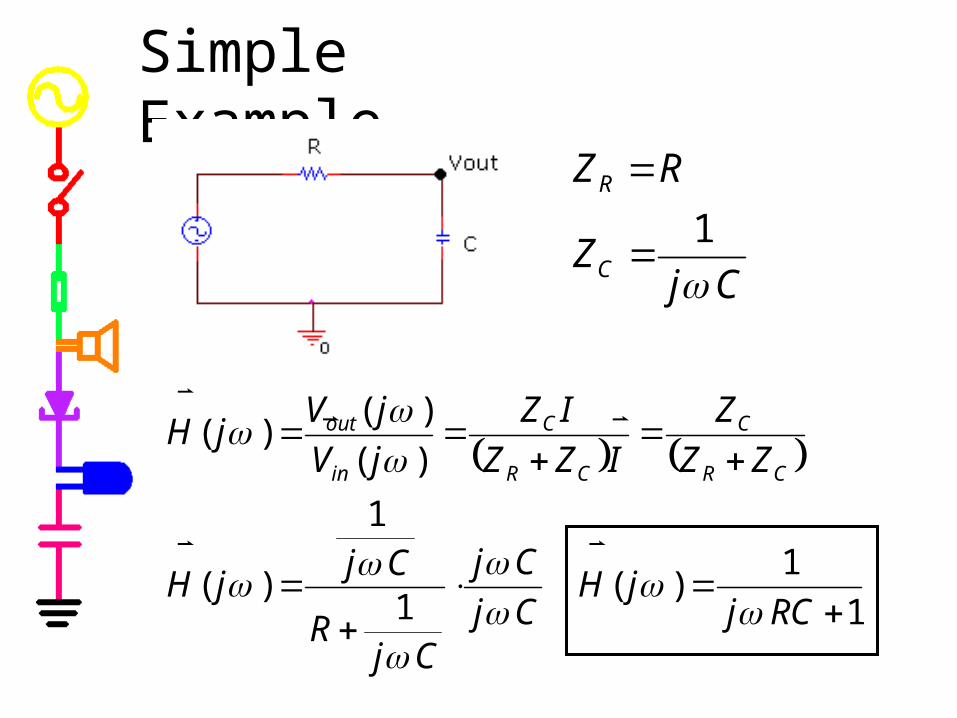
Simple Example
1
1)(
1
1
)(
)(
)()(
RCjjH
Cj
Cj
CjR
CjjH
ZZ
Z
IZZ
IZ
jV
jVjH
CR
C
CR
C
in
out
CjZ
RZ
C
R
1

Simple Example (continued)
1
1)(
RCjjH
222
22
)(1
1
)(1
01
1
01)(
RCRCRCj
jjH
)(tan1
tan1
0tan)(
)1()01()(
111 RCRC
jH
RCjjjH
2)(1
1)(
RCjH
)(tan)( 1 RCjH
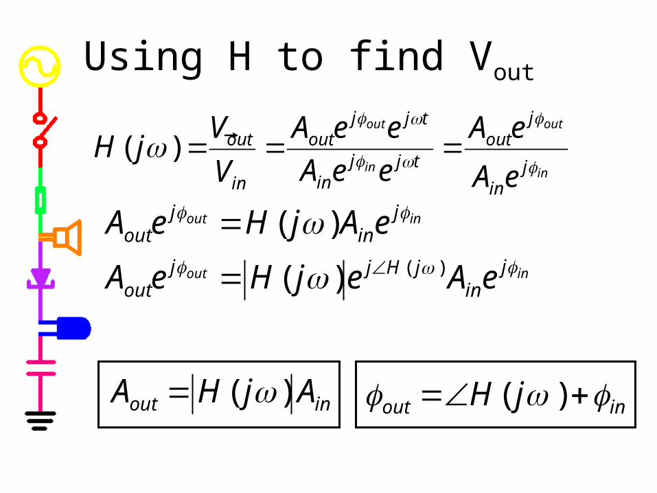
Using H to find Vout
in
out
in
out
jin
jout
tjjin
tjjout
in
out
eA
eA
eeA
eeA
V
VjH
)(
inout
inout
jin
jHjjout
jin
jout
eAejHeA
eAjHeA
)()(
)(
inout AjHA )( inout jH )(

Simple Example (with numbers)
157.0)2(1
1)(
2
2
jH 41.11
2tan0)( 1
jH
)4
2cos(2)(
11
tKVtV
KRFC
in
)41.1785.02cos(2*157.0)( tKVtVout
12
1
1112
1
1
1)(
jKKjRCjjH
)625.02cos(314.0)( tKVtVout
Part A -- RC and RL Circuits
High and Low Pass Filters H and Filters

High and Low Pass FiltersHigh Pass Filter
H = 0 at 0
H = 1 at
at c
Frequency
1.0Hz 100Hz 10KHz 1.0MHz 100MHzV(C1:2) / V(R1:2)
0
0.5
1.0
Frequency
1.0Hz 100Hz 10KHz 1.0MHz 100MHzV1(R1) / V(C1:2)
0
0.5
1.0
Low Pass Filter
H = 1 at 0
H = 0 at
at c
c=2fc
fc
fc
c=2fc

Corner Frequency The corner frequency of an RC or RL circuit
tells us where it transitions from low to high or visa versa.
We define it as the place where
For RC circuits:
For RL circuits:
2
1)( cjH
L
Rc
RCc
1

Corner Frequency of our example
212 RC 2
2
1 RC
RCjjH
1
1)(
2
1)( jH
2
1
)(1
1
2
1
)(1
1)(
22
RCRCjH
RCc
1
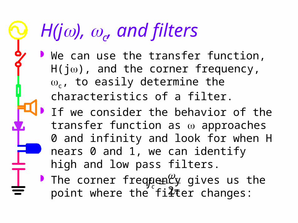
H(j), c, and filters We can use the transfer function, H(j), and the
corner frequency, c, to easily determine the characteristics of a filter.
If we consider the behavior of the transfer function as approaches 0 and infinity and look for when H nears 0 and 1, we can identify high and low pass filters.
The corner frequency gives us the point where the filter changes:
2
ccf

Our example at low frequencies
)(01
0tan)(
110)(
1 axisxonjH
asjH
LOW
LOW
RCjjH
1
1)(
101
1)(
jH LOW
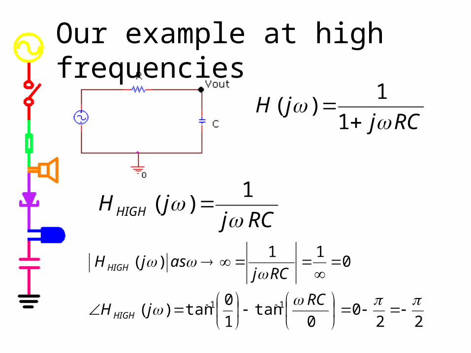
Our example at high frequencies
220
0tan
1
0tan)(
011
)(
11
RCjH
RCjasjH
HIGH
HIGH
RCjjH
1
1)(
RCjjH HIGH 1
)(

Our example is a low pass filter
Frequency
1.0Hz 100Hz 10KHz 1.0MHz 100MHzV(C1:2) / V(R1:2)
0
0.5
1.0
RCf c
c
2
1
2
01 HIGHLOW HH
What about the phase?

Our example has a phase shift
0
1
HIGH
LOW
H
H
Frequency
1.0Hz 10KHz 100MHzVP(C1:2)
-100d
-50d
0dV(R1:2) / V(V1:+)
0
0.5
1.0
SEL>>
90)(
0)(
jH
jH
HIGH
LOW

Taking limits
012
2
012
2)(bbb
aaajH
At low frequencies, (ie. =10-3), lowest power of dominates
At high frequencies (ie. =10+3), highest power of dominates
0
00
03
16
2
00
31
62
101010
101010)(
b
a
bbb
aaajH
2
20
03
16
2
00
31
62
101010
101010)(
b
a
bbb
aaajH

Capture/PSpice Notes Showing the real and imaginary part of the signal
• in Capture: PSpice->Markers->Advanced• ->Real Part of Voltage
• ->Imaginary Part of Voltage
• in PSpice: Add Trace• real part: R( )
• imaginary part: IMG( )
Showing the phase of the signal• in Capture:
• PSpice->Markers->Advanced->Phase of Voltage
• in PSPice: Add Trace• phase: P( )

Part B -- RLC Circuits
Band Filters Another example A more complex example

Band Filters
Frequency
1.0Hz 100Hz 10KHz 1.0MHz 100MHzV(L1:1) / V(V1:+)
0
0.5
1.0
Frequency
1.0Hz 100Hz 10KHz 1.0MHz 100MHzV(R1:1)/ V(R1:2)
0
0.5
1.0
f0
f0
Band Pass Filter
H = 0 at 0
H = 0 at
at 0=2f0
Band Reject Filter
H = 1 at 0
H = 1 at
at 0 =2f0

Resonant Frequency The resonant frequency of an RLC circuit tells
us where it reaches a maximum or minimum. This can define the center of the band (on a band
filter) or the location of the transition (on a high or low pass filter).
We are already familiar with the equation for the resonant frequency of an RLC circuit:
LC
10

Another Example
1
11
1
)(22
LCjRCj
CjLjR
CjjH
CjZ
LjZRZ
C
LR
1
RCjLCjH
)1(
1)(
2

At Very Low Frequencies
0)(
10)(
11
1)(
jH
jH
jH
LOW
LOW
LOW
At Very High Frequencies
orjH
jH
LCjH
HIGH
HIGH
HIGH
)(
01
)(
1)(
2

At the Resonant Frequency
LC
10
RCjLCjH
)1(
1)(
2
LC
RCjRC
LCjLC
LC
jH
)11(
1
1)
11(
1)( 20
2)(
)(
)(
0
0
0
jH
RC
LCjH
RC
LCjjH
if L=10uH, C=1nF and R=1K
rad/secfHz
LCf
21
0
radiansH2

Our example is a low pass filter
Frequency
1.0Hz 10KHz 100MHzV(R1:2) / V(V1:+)
0
0.5
1.0P( V(R1:2))
-200d
-100d
0d
SEL>>
Phase
= 0 at 0
= - at Magnitude
= 1 at 0
= 0 at
fHz
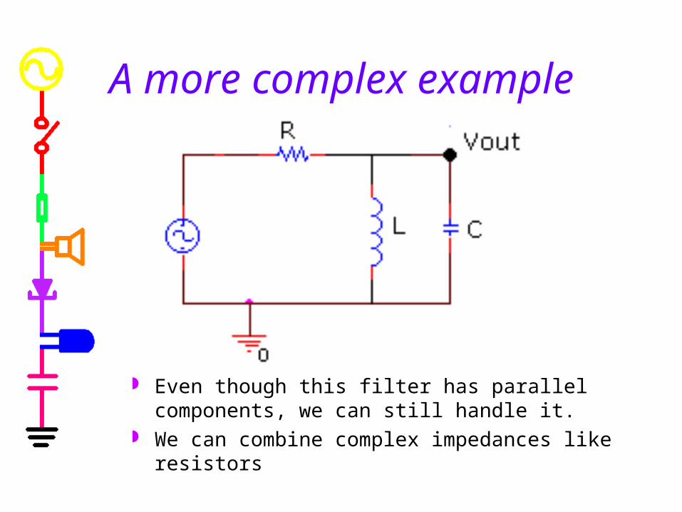
A more complex example
Even though this filter has parallel components, we can still handle it.
We can combine complex impedances like resistors

Determine H
LC
Lj
LCj
Lj
CjLj
CjLj
ZCL 222 111
1
LjLCR
LjjH
)1()(
2
LC
LCbymultiply
LCLj
R
LCLj
ZR
ZjH
CL
CL2
2
2
2
1
1
1
1)(

At Very Low Frequencies
2)(
00)(
)(
jH
jHR
LjjH
LOW
LOW
LOW
At Very High Frequencies
2)(
01
)(
)(2
jH
jH
RC
j
LRC
LjjH
HIGH
HIGH
HIGH

At the Resonance Frequency
11
)1
1(
1
)( 20
LLC
jLCLC
R
LLC
j
jH
0)(1)( 00 jHjH
LC
10

Frequency
1.0Hz 10KHz 100MHzVP(R1:1)
-100d
0d
100d
SEL>>
V1(R1) / V(V1:+)0
0.5
1.0
Our example is a band pass filter
Phase
= 90 at 0
= 0 at
= - at
Magnitude
= 0 at 0
H=1 at
= 0 at
f

Simple Filter Design Step One: Pick a High Pass or Low Pass
Filter Configuration • This is done by looking at the high or low
frequency limit of various simple circuits. • For example, for an RC low pass filter, we
choose the following configuration:R1
0
V1
FREQ = VAMPL = VOFF = C1
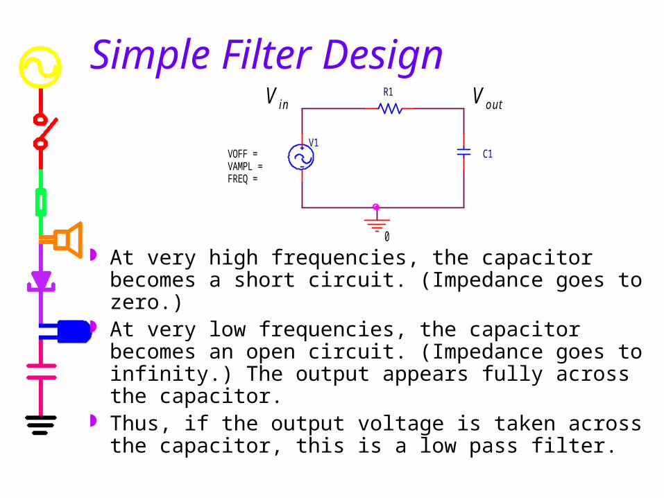
Simple Filter Design
At very high frequencies, the capacitor becomes a short circuit. (Impedance goes to zero.)
At very low frequencies, the capacitor becomes an open circuit. (Impedance goes to infinity.) The output appears fully across the capacitor.
Thus, if the output voltage is taken across the capacitor, this is a low pass filter.
R1
0
V1
FREQ = VAMPL = VOFF = C1
V o u tV in
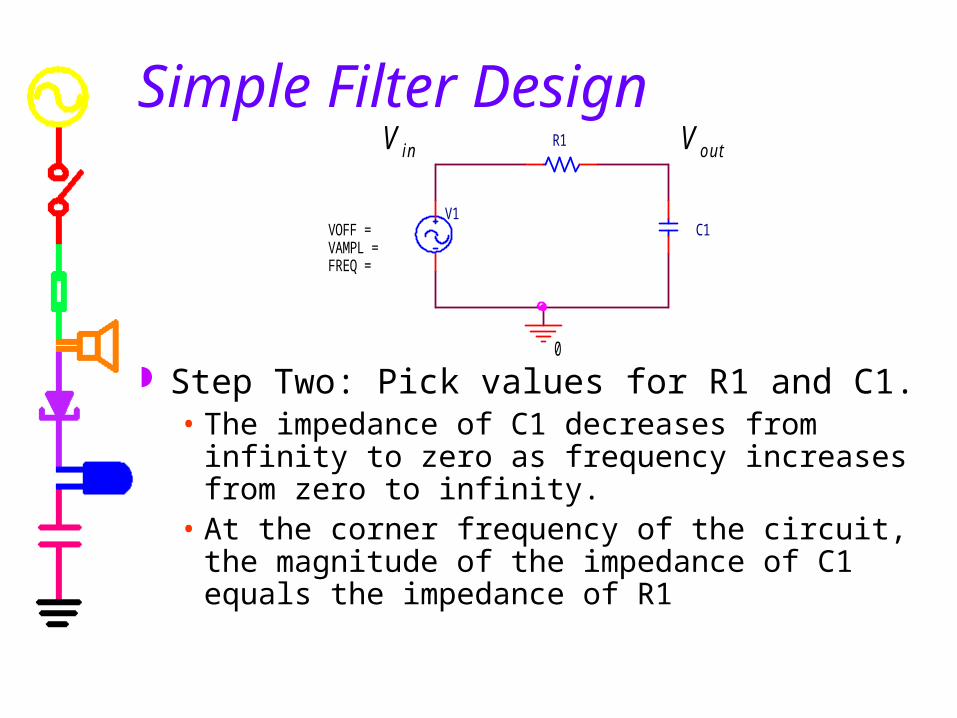
Simple Filter Design
Step Two: Pick values for R1 and C1.• The impedance of C1 decreases from infinity to
zero as frequency increases from zero to infinity.
• At the corner frequency of the circuit, the magnitude of the impedance of C1 equals the impedance of R1
R1
0
V1
FREQ = VAMPL = VOFF = C1
V o u tV in
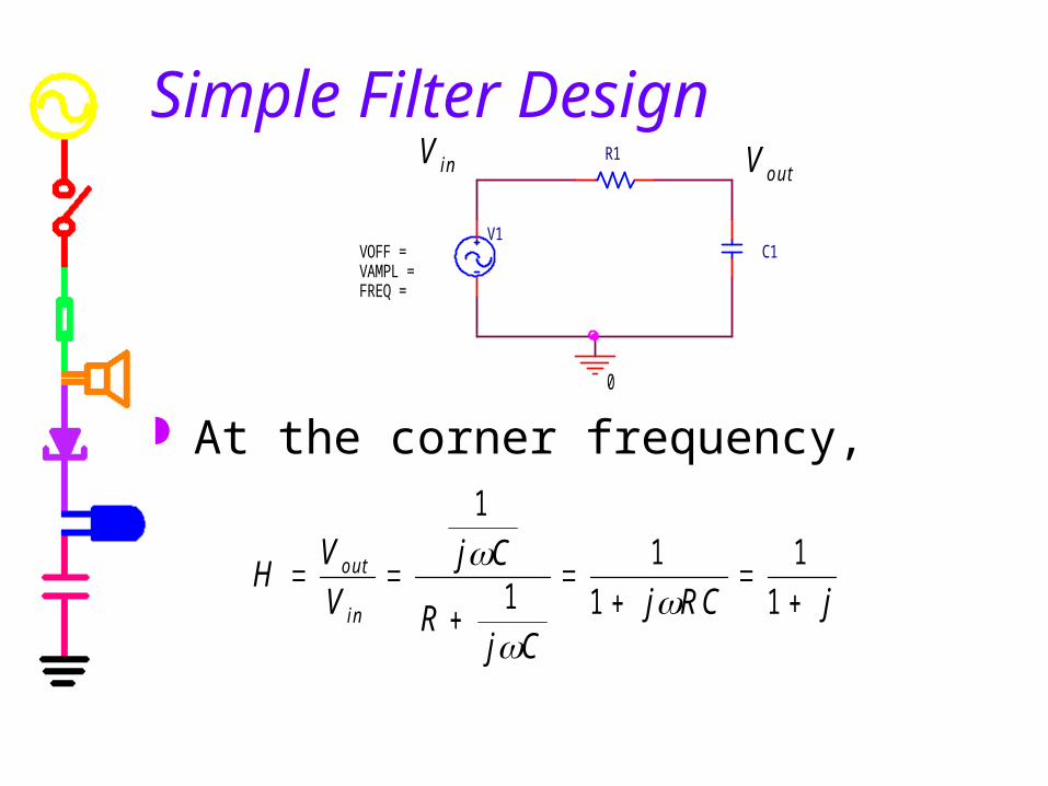
Simple Filter Design
At the corner frequency,
R1
0
V1
FREQ = VAMPL = VOFF = C1
HV
Vj C
Rj C
j R C jo u t
in
1
11
1
1
1
V o u tV in

Simple Filter Design
The magnitude of H at the corner frequency is 0.707.
R1
0
V1
FREQ = VAMPL = VOFF = C1
HV
V jo u t
in
1
1
1
20 7 0 7.
V o u tV in

Simple Filter Design
Thus, for frequencies less than the corner frequency, Vout is comparable to Vin.
For frequencies greater than the corner frequency, the output is much smaller than the input.
R1
0
V1
FREQ = VAMPL = VOFF = C1
V o u tV in

Example
For this example, we select components from our boxes of parts to pass most frequencies below 100Hz.
For R=50 and C=33uF, the corner frequency is about 96Hz.
Frequency
1.0Hz 3.0Hz 10Hz 30Hz 100Hz 300Hz 1.0KHz 3.0KHz 10KHzV(R2:2)/ V(R1:2)
0
0.2
0.4
0.6
0.8
1.0
VV1
FREQ = 1kVAMPL = 1VOFF = 0
R1
50
R2
50
C1
33uF
V
0
V in V o u t
Top Related