


Languages
Pages
Legal

Electrical Connectionsof Main Spindle Drives
DOK-GENERL-MAIN*EL*CON-PRJ1-EN-P
Project Planning Manual
mannesmannRexroth
engineering
Indramat258653

2• DOK-GENERL-MAIN*EL*CON-PRJ1-EN-E1,44 • 07.97
About this documentation
Electrical Connections of Main Spindle Drives
Project Planning Manual
DOK-GENERL-MAIN*EL*CON-PRJ1-EN-E1,44
• 209-0042-4111-00
This electronic document is based on the hardcopy document with documentdesig.: 209-0042-4111-00 EN/04.94
This documentation serves:
– to introduce and categorize the connections of the main spindle drives,
– as a source for the circuit diagrams for not only the power connections butalso the feedback and CNC connections when developing the machinecircuit diagrams,
– to offer a table summary of assembled cables and their construction,
– to make customer-specific cables possible,
– to identify the plugs and cables supplied.
This documentation
– applies to all main spindle drives,
– correlates with the „Project Planning Notes“ for main spindle controllers andmain spindle motors. This documentation can be referenced via text strings.
Titel
Type of documentation:
Documenttype
Internal file reference
Reference
This documentationis used:
© INDRAMAT GmbH, 1994Copying of this document, and giving it to others and the use or communicationof the contents thereof, are forbidden without express authority. Offenders areliable to the payment of damages.All rights are reserved in the event of the grant of a patent or the registrationof a utility model or design. (DIN 34-1)
The electronic documentation (E-doc) may be copied as often as needed ifsuch are to be used by the consumer for the purpose intended.
All rights reserved with respect to the content of this documentation and theavailability of the products.
INDRAMAT GmbH • Bgm.-Dr.-Nebel-Straße 2 • D-97816 LohrTelefon 0 93 52 / 40-0 • Tx 689421 • Fax 0 93 52 / 40-48 85
Dept ENA (MR, FS)
Copyright
Validity
Publisher
Designation of documentation Release- Comentsup to present edition date
209-0042-4111-00 EN/04.94 Apr/94 First Edition
DOK-GENERL-MAIN*EL*CON-PRJ1-EN-E1,44 Jul./97 First E-Dok
Change procedures

3• DOK-GENERL-MAIN*EL*CON-PRJ1-EN-E1,44 • 07.97
Table of Contents
1. Electrical Connections 7
1.1. Standardization ......................................................................7
1.2. Types ...................................................................................10
1.3. Determination of Size and Guidelines ..................................13
2. Power Connections 15
2.1. Motor-Controller Power Connections ...................................15
2.1.1. Breakdown of the Types of Connections ..........................16
2.1.2. Connection Plans for Direct Connections .........................19
2.1.3. Assembled Data List .........................................................29
2.1.4. Line Specifications ............................................................45
2.2. Power connections of the RAC three-phase mains .............46
2.2.1. Three-Phase Mains Requirements ...................................47
2.2.2. Connection Plans ..............................................................49
2.2.3. Connecting Components Data List ...................................52
3. Feedback and CNC Connections 56
3.1. Types of feedback and CNC connections ............................57
3.2. Connecting plans for direct connections ..............................60
3.2.1. Motor feedback, high-resolution ........................................61
3.2.2. Motor feedback, incremental encoder ...............................63
3.2.3. Spindle Feedback, high-resolution ....................................64
3.2.4. Spindle Feedback, incremental encoder ...........................66
3.2.5. Lead Spindle Feedback ....................................................67
3.2.6. Control input, signal and analogue outputs, Bb-contact ...68
3.2.7. Speed set-point, analogue +/- 10V ...................................69
3.2.8. Speed set-point, digital, 16 bit parallel ..............................70
Page
Table of Contents
4• DOK-GENERL-MAIN*EL*CON-PRJ1-EN-E1,44 • 07.97
Table of Contents
3.2.9. SERCOS Interface ............................................................71
3.2.10. Position set-point, digital, 16 bit parallel ..........................72
3.2.11. Serial interface RS 232C ................................................73
3.2.12. Incremental encoder output ............................................74
3.2.13. Control of the mains contactor integrated into the RACcontroller .........................................................................75
3.3. Assembled Cable Specifications ..........................................76
3.4. Line Specifications List ........................................................84
4. Installation Guidelines 85
5. Delivery, Identification, Storage 88
6. Customizing Specifications 91
7. Index 94
8. Supplementary Documentation 99

5• DOK-GENERL-MAIN*EL*CON-PRJ1-EN-E1,44 • 07.97
Table of Contents

6• DOK-GENERL-MAIN*EL*CON-PRJ1-EN-E1,44 • 07.97

7• DOK-GENERL-MAIN*EL*CON-PRJ1-EN-E1,44 • 07.97
1. ElectricalConnections
1.1. Standardization
1. Electrical Connections
The electrical connections in the entire INDRAMAT main spindledrive program have been standardized with the goal of reducing therange of cables available.
There are three categories of electrical connections:
– power connections
– feedback and CNC connections
– controller-specific connections
The motor connections to the main spindle controller always have thesame terminal assignment, regardless of the controller implemented.The cable cross sectional area is dependent on the motor powerrequirements.
The RAC controller is connected directly to the three-phase mains.The terminal assignments of the different RAC’s are always thesame. The cable cross sectional area is dependent on the currenttype of the respective RAC.
Plug assignment is the same regardless of controller and motor type.
The KDA/TDA controllers used in modular drive packages havecontroller-specific electrical connections. This documentation doesnot deal with their connection. It is dealt with in the documentation onmain spindle controllers KDA 3.2, or TDA 1.1, „Project PlanningNotes“. The cables needed are part of the electrical connectingaccessories E...-.DA.
The mains contactor and the respective control circuits are integratedinto the RAC controllers for direct mains connection. The facilitycontrol system must operate this control circuit. The controller-specific connections are outlined in the mains connection plans inSection 2.2.
Power connections
Feedback andCNC connections
Controller-specific connections

8• DOK-GENERL-MAIN*EL*CON-PRJ1-EN-E1,44 • 07.97
Spe
ed s
et-p
oint
Control
Con
trol
ler"
Rea
dy"
cont
act
Add
ition
al c
ontr
olle
r in
terf
ace
- In
crem
enta
l enc
oder
out
put
- S
eria
l int
erfa
ce R
S 2
32 C
- P
ositi
on s
et-p
oint
Con
trol
inpu
t and
sig
nal o
utpu
ts
of th
e co
ntro
ller
Motor fan connection
Motor connections
Motor feedback
connection
Spindle feedback
Lead spindle feedback
Feedback and CNC
connections
Katelvem
Mains
Controller-specificconnections
Power connections
Mains
Supplyunit
KDA/TDA
(only with KDA)
Figure 1.2: Categories of electrical connections for main spindle drives with KDA/TDA
1. Electrical Connections
9• DOK-GENERL-MAIN*EL*CON-PRJ1-EN-E1,44 • 07.97
X 4
X 2 X 3
X 5X 1 3
Prog. Modul AS nicht unter Spannung wechseln
ASSWITCH OFF VOLTAGE BEFORE
CHANGING MODULE AS
X 1
Q 1
X 6
AC-MAINSPINDLE DRIVE RAC 2
L -
L +
DANGER HIGH VOLTAGEDISCHARGE TIMEEntladezeit 1Min.
Mains
Spe
ed s
et-p
oint
Mai
ns c
onta
ctor
ON
Mai
ns c
onta
ctor
OF
F
Control
Mai
ns c
onta
ctor
m
onito
ring
Con
trol
ler
"rea
dy"
cont
act
Add
ition
al c
ontr
olle
r in
terf
ace
- In
crem
enta
l enc
oder
out
put
- S
eria
l int
erfa
ce R
S 2
32 C
- P
ositi
on s
et-p
oint
Con
trol
inpu
t and
sig
nal o
utpu
ts
of th
e co
ntro
ller
Mains connections
Powerconnections
Motor fan connections
Motor connections
Motorfeedback
connections
Spindlefeedback
Lead spindle feedback
Controller-specific
connections
Feedbackand CNC
connections
Katelvek
Internal control
circuit and mains
contactor
RAC
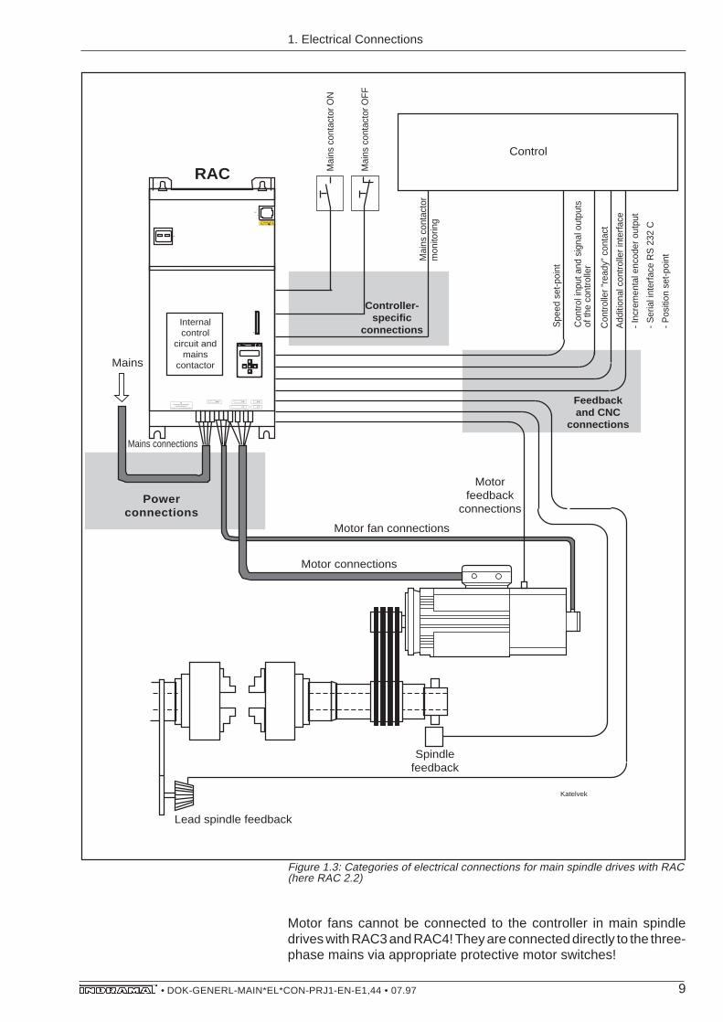
Figure 1.3: Categories of electrical connections for main spindle drives with RAC(here RAC 2.2)
Motor fans cannot be connected to the controller in main spindledrives with RAC3 and RAC4! They are connected directly to the three-phase mains via appropriate protective motor switches!
1. Electrical Connections
Holding brake

10• DOK-GENERL-MAIN*EL*CON-PRJ1-EN-E1,44 • 07.97
1.2. Types The electrical connections of all categories are available as
– assembled (ready to use), or,
– components (individual parts, not ready to use).
Assembled cables are supplied in the lengths ordered and guaranteea quick and easy assembly of control cabinet and machine. If onlyassembled cables are used, then no addditional cable and plugaccessories are needed.
Component electrical connections are made up of individual, assem-bled parts. The specifications of these parts are listed in the table.These must then be assembled in accordance with the guidelinesoutlined in Section 5.
Power connections
Assembled Components
To the motorNo additional plugor cable accessoriesneeded!
To the three-phase mainsNot available
To the motor- Power plug/compression cable
shoe on the motor- Wire-end ferrule/crimping cable
lug on the controller- CableTo the three-phase mains(with RAC)- Wire-end ferrule/crimping cable
lug- Cable
1. Electrical Connections
Figure 1.4: Specifications of the power connections with accessories referenced.
11• DOK-GENERL-MAIN*EL*CON-PRJ1-EN-E1,44 • 07.97
1. Electrical Connections
Feedback and CNC Connections
Partiallyassembled
ComponentsExclusivelyassembled
Additional plugconnectors andcables for the non-assembled connec-tions.
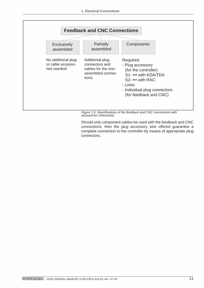
Figure 1.5: Specifications of the feedback and CNC connections withaccessories referenced.
Required:- Plug accessory
(for the controller)S1- ••• with KDA/TDAS2- ••• with RAC
- Lines- Individual plug connectors
(for feedback and CNC)
No additional plugor cable accesso-ries needed!
Should only component cables be used with the feedback and CNCconnections, then the plug accessory sets offered guarantee acomplete connection to the controller by means of appropriate plugconnectors.

12• DOK-GENERL-MAIN*EL*CON-PRJ1-EN-E1,44 • 07.97
Componentsfor RAC
Connections onlyobtainable fromINDRAMAT as part of themodular drive package(part of the electricalconnecting accessoriesE•• - KDA orE•• - TDA)
Assembled forKDA/TDA
Controller Connections
Figure 1.6: Construction of controller-specific connections with electricalconnecting accessories referenced.
1. Electrical Connections
Plug connector withoutcable to contact RACinternal control circuit(part of electricalconnecting accessoriesE1-RAC).
The controller-specific connections are always required! The electri-cal connection accesssories within the KDA/TDA modular drivepackage are dependent upon the adjacent controller in the drivepackage (see documentation main spindle controller; „Project Plan-ning Notes“).
13• DOK-GENERL-MAIN*EL*CON-PRJ1-EN-E1,44 • 07.97
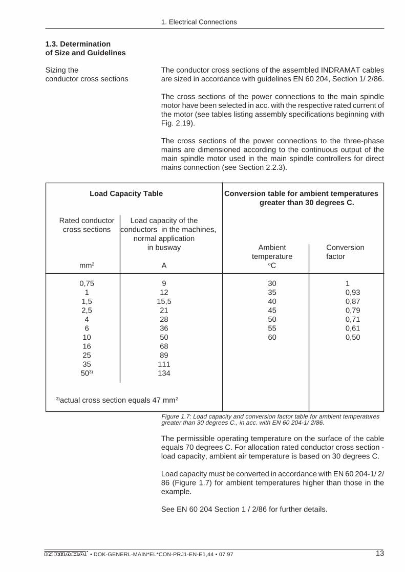
1.3. Determinationof Size and Guidelines
The conductor cross sections of the assembled INDRAMAT cablesare sized in accordance with guidelines EN 60 204, Section 1/ 2/86.
The cross sections of the power connections to the main spindlemotor have been selected in acc. with the respective rated current ofthe motor (see tables listing assembly specifications beginning withFig. 2.19).
The cross sections of the power connections to the three-phasemains are dimensioned according to the continuous output of themain spindle motor used in the main spindle controllers for directmains connection (see Section 2.2.3).
Sizing theconductor cross sections
Load Capacity Table Conversion table for ambient temperaturesgreater than 30 degrees C.
Rated conductor Load capacity of thecross sections conductors in the machines,
normal applicationin busway Ambient Conversion
temperature factormm2 A oC
0,75 9 30 11 12 35 0,93
1,5 15,5 40 0,872,5 21 45 0,794 28 50 0,716 36 55 0,61
10 50 60 0,5016 6825 8935 111503) 134
3)actual cross section equals 47 mm2
1. Electrical Connections
Figure 1.7: Load capacity and conversion factor table for ambient temperaturesgreater than 30 degrees C., in acc. with EN 60 204-1/ 2/86.
The permissible operating temperature on the surface of the cableequals 70 degrees C. For allocation rated conductor cross section -load capacity, ambient air temperature is based on 30 degrees C.
Load capacity must be converted in accordance with EN 60 204-1/ 2/86 (Figure 1.7) for ambient temperatures higher than those in theexample.
See EN 60 204 Section 1 / 2/86 for further details.

14• DOK-GENERL-MAIN*EL*CON-PRJ1-EN-E1,44 • 07.97
Sizing maximum cable lengths Maximum cable length is limited by the electro-magnetic distortionsand the loss of voltage along the cable. Transit time effects in themotor power cable cause cable-length dependent voltage increasesat the motor terminals. This also limits cable lengths.
The maximum cable lengths given reference the direct connectionbetween controller and motor, or feedback, in those cases whereassembled INDRAMAT cables are used, and an ambient tempera-ture of 30 degrees C is maintained in accordance with VDE 0113.
Terminal points and intermediate couplings can reduce maximumcable length.
– Power connection to motor: 75 m
– Feedback connection: 75 m
1. Electrical Connections

15• DOK-GENERL-MAIN*EL*CON-PRJ1-EN-E1,44 • 07.97
2. Power Connections
2. Power Connections
INDRAMAT main spindle drives have power connections betweenthe controller and motor and between the RAC controller and thethree-phase mains.
The power connections between motor and controller are brokendown into Sections:
Section 2.1.1: Division of the types of connections
– direct connection motor-controller
– connection with intermediate terminal
– connection with plug design
– connection with plugin testing points
Section 2.1.2: Connection plans for direct connection of motor andmotor fan of
– 2AD 100 and 2AD 101 with air flow A->B
– 2AD 100 and 2AD 101 with air flow B->A
– 2AD 132 with power connector
– 2AD 132, 2D 160, 2AD 180, 2AD 200 and 2AD 225 with terminal box
– 1MB frameless spindle motor (water cooled)
Section 2.1.3: Table of assembled cable specifications for
– motor-controller direct connection and connection with intermedi-ate terminal
– connection with plug design
– connection with plugin testing points
Section 2.1.4: Table of cable specifications such as
– type designation,
– conductor cross section,
– cable construction,
– cable diameter,
– bending radii, and,
– length-related weight.
2.1. Motor-ControllerPower Connections

16• DOK-GENERL-MAIN*EL*CON-PRJ1-EN-E1,44 • 07.97
There are four types of assembled power connections betweenmotor and controller.
2.1.1. Breakdown of theTypes of Connections
Motor-controllerdirect connection
direct with intermediate terminal plug withplugin
to terminal strip design testing points
Types of power connectionsmotor-controller
Power plugconnector (plug)
Symbols:
wire end ferrulefor line-up terminals
crimping cable lug for stay bolts
Flange connector
Power plugconnector (coupling)
On the motor Cable On the controller
(2AD main spindle motor, 1MB frameless spindle motor)
(2AD main spindle motor, 1MB frameless spindle motor)
(Controller KDA/TDA or RAC4)
(Controllers RAC2/RAC3)
st_verb1
2. Power Connections
Figure 2.2: Assembled power cables for direct connections(also see Figs. 2.19 and 2.20 for 2AD, and for 1MB see Figs. 2.25 through2.27).
This type of connection is characterized by the lowest number ofimperfections and the lowest drop in voltage in comparison to theother types of connections.
A terminal point for the strand pair of the holding brake must belocated close to the motor power connection on the controller in thecontrol cabinet, if main spindle drives with holding brakes are used!
Figure 2.1: The four types of power connections

17• DOK-GENERL-MAIN*EL*CON-PRJ1-EN-E1,44 • 07.97
Motor-controller connection withintermediate terminal
With this type of connection it is easy for the CNC control to takecharge of the electrical holding brake, or to be integrated into thecontrol circuit.
The intermediate terminal at a terminal strip also makes it possible toreroute a space-saving, sheathless cable into the cable conduits ofthe control cabinet!
On the motor Cable Terminal strip Cable On the controller
(2AD main spindle motor, 1MB frameless spindle motor)
(2AD main spindle motor, 1MB frameless spindle motor)
(Controllers KDA/TDA or RAC4)
(Controllers RAC2/RAC3)
st_verb2
Power plugconnector (plug)
Symbols:
wire-end ferrulefor line-up terminals
crimping cable lug for stay bolts
Flangeconnector
Power plug connector (coupling)
Motor-controller connectionwith plug design
On the motor Cable Plug Cable On the controller
(2AD main spindle motor, 1MB frameless spindle motor)
(2AD main spindle motor, 1MB frameless spindle motor)
(Controllers KDA/TDA or RAC4)
(Controllers RAC2/RAC3)
design
ST_VERB3
Power plugconnector (plug)
Symbols:
Wire-end ferrule forline-up terminals
Crimping cable lug for stay bolts
Flangeconnector
Power plugconnector (coupling)
2. Power Connections
Figure 2.3: Assembled power cable with intermediate terminal at terminal strip(also see Figs. 2.19 and 2.20 for 2AD, Figs. 2.25 through 2.27 for 1MB).
This type of connection makes it possible to finish the control cabinetentirely independent of the machines.
In addition, damaged cables can be very quickly and reliably ex-changed.
Figure 2.4: Assembled power cable with plug design (also see Figs. 2.21and2.22 for 2AD, see Figs. 2.28 through 2.30) for 1MB.

18• DOK-GENERL-MAIN*EL*CON-PRJ1-EN-E1,44 • 07.97
Motor-controller connectionwith plugin testing points
This connection type is advantageous for larger facilities because itis possible to quickly and reliably exchange the damaged section ofa cable.
The mounting of assembled cables of this type is particularly simpleand quick.
Figure 2.5: Assembled power cable with plugin testing points (also see figure2.23, 2.24 for 2AD, see Figs. 2.31 through 2.33 for 1MB) .
The assembled cable with the power plug connectors at both ends(plug/coupling) can be added as an extension piece between theplugin testing points.
On the motor Cable Plug Cable On the controller
(2AD main spindle motor, 1MB frameless spindle motor)
(2AD main spindle motor, 1MB frameless spindle motor)
(Controllers KDA/TDA or RAC4)
(Controllers RAC2/RAC3)
design
ST_VERB4
Power plugconnector (plug)
Symbols:
Wire-end ferrulefor line-up terminals
Crimping cable lug for stay bolts
Flangeconnector
Power plugconnector (coupling)
2. Power Connections

19• DOK-GENERL-MAIN*EL*CON-PRJ1-EN-E1,44 • 07.97
2.1.2. Connection Plans forDirect Connections
Only the connection plans for the direct connection of the motor-controller power connections are depicted. They also, however,apply to all other connections types. The respective testing points donot alter the arrangement of motor and controller connections.
The connection plans assist in constructing the facility wiring dia-grams. The facility circuit diagrams of the machine manufacturershould be used when wiring the facility!
The technical specifications for the motor, the holding brake (op-tional) and the motor fan are dealt with in the documentation on therespective main spindle motor - project planning notes. The docu-mentation also includes a recommendation for the selection of theprotective motor switch for the motor fan.
If a main spindle motor with holding brake is used, then the controlcabinet must supply it with +24V +/-10%. The facility control systemcontrols the holding brake.
The criteria for the holding brake control system are –
– the operating principle of the holding brake, and,
– monitors the powering down of the motor (N<Nmin).
The respective application determines all other criteria.
Monitoring of motor shutdown (N<Nmin) is explained in the documententitled „AC Main Spindle Drives with Controlled AsynchronousMotors or Frameless Spindle Motors; Description of Application“.
2. Power Connections
Technical Data
Motor with Holding Brake

20• DOK-GENERL-MAIN*EL*CON-PRJ1-EN-E1,44 • 07.97
2. Power Connections
Figure 2.6: Connection of 2AD 100 motor with air flow from A->B and 2AD 101with terminal box to motor fan.
APMOT001
Motor fan connection:
M
31
2
3
L
N
PE
0,75 … 1,5 mm2
0,75 … 1,5 mm2
terminal box
Identifying the rated connection voltage of the motor fan in the motor type designation2AD 100 • - • • • • • • - • • • • - • • • •2AD 101 • - • • • • • • - • • • • - • • • •
Permissible mains voltage:AC 220 V ±10%, 50...60 Hz : 2 (1 only with 2AD101)AC 115 V ±10%, 50...60 Hz : 5
7 0,75 … 1,5 mm2
8 0,75 … 1,5 mm2
6 0,75 … 1,5 mm2
5 0,75 … 1,5 mm2
gn/yel cross section motor type
1 dep. (see table
2 assembled specifications)
3
KDA / TDAcontroller
2
1
3
A1
A2
A3
X8
X12
E
D
A
B
C
H
Jϑ
U
F
G0V
+24V
Crimping cable lug for stay bolts M6
Plug terminal part of elec. connectionE • • - • DA
Power plug connectorCable(numbering of strands as per INDRAMAT standard)
operated by control circuit
2AD 100 • - • • • • • • - . . .2AD 101 • - • • • • • • - . . .
2AD 100 motor connection (cooling air flow A => B) and 2AD 101 (motor fan with terminal box)
motor fan
M
3
NL
I>>
capacitor
motor fanwindings
1 2 3
I>>
ge/gr
Shield
7856
12
3
200140 approx. 130
50
3030Tightening
length
IN 172/••
(Assembled power cable IKL•••/IKF•••)
Dimension as per tech. specs of motor fan (see doc. 2AD•••, project planning notes)
Mains connection 5...8 mm
A, B, R or L 2 or 5

21• DOK-GENERL-MAIN*EL*CON-PRJ1-EN-E1,44 • 07.97
APMOT002
Motor fan connection:
M
1
2
3
L
N
PE
0,75 … 1,5 mm2
0,75 … 1,5 mm2
Plug connector
Identifying the rated connection voltage of the motor fan in the motor type designation2AD 100 • - • • • • • • - • • • • - • • • •
Permissible mains voltage:AC 220 V ±10%, 50...60 Hz : 1AC 115 V ±10%, 50...60 Hz : 4
7 0,75 … 1,5 mm2
8 0,75 … 1,5 mm2
6 0,75 … 1,5 mm2
5 0,75 … 1,5 mm2
gn/yel cross section motor type
1 dep. (see table
2 assembled specifications)
3
KDA / TDAcontroller
2
1
3
A1
A2
A3
X8
X12
E
D
A
B
C
H
Jϑ
U
F
G0V
+24V
operated bycontrol circuit
main spindle motor 2AD 100 • - • • • • • • - . . .
2AD 100 motor connection (cooling air flow B => A)
motor fan
M
3
NL
I>>
I>>
Dimension as per tech. specs of motor fan (see doc. 2AD•••, project planning notes)
approx. 50 untightened
40
26,5
26,5
15,5
Crimping cable lug for stay bolts M6
Plug terminal, part of elec. connectionE • • - • DA
Power plug connectorCable(numbering of strands as per INDRAMAT standard)
ge/gr
Shield
7856
12
3
200140approx. 130
50
3030Tightening
length
IN 172/••
(assembled power cable IKL•••/IKF•••)
Mains connection 5...8 mm
1 or 4
2. Power Connections
Figure 2.7: Connection of 2AD 100 motor with air flow from B->A.

22• DOK-GENERL-MAIN*EL*CON-PRJ1-EN-E1,44 • 07.97
Figure 2.8: Connection of 2AD 101 motor with plug connector to motor fan.
APMOT005
Motor fan connection:
M
1
2
L
N
PE
0,75 … 1,5 mm2
0,75 … 1,5 mm2
Plug connector
Identifying rated connection voltage of the motor fan in the motor type designation2AD 101 • - • • • • • • - • • • • - • • • •
Permissible mains voltage:AC 220 V ±10%, 50...60 Hz : 1 or 2AC 115 V ±10%, 50...60 Hz : 5
7 0,75 … 1,5 mm2
8 0,75 … 1,5 mm2
6 0,75 … 1,5 mm2
5 0,75 … 1,5 mm2
gn/yel cross section motor type
1 dep. (see table
2 assembled specifications)
3
KDA / TDAcontroller
2
1
3
A1
A2
A3
X8
X12
E
D
A
B
C
H
Jϑ
U
F
G0V
+24V
operated by control circuit
main spindle motor 2AD 101 • - • • • • • • - . . .
2AD 101 motor connection (motor fan with plug connector)
motor fan
M
3
NL
I>>
I>>
Dimension as per tech. specs of motor fan (see doc. 2AD•••, project planning notes)
Crimping cable lugfor stay bolts M6
Plug terminal, part of elec. connection acc.E • • - • DA
Power plug connectorCable(numbering of strands as per INDRAMAT standard)
ge/gr
Shield
7856
12
3
200140approx. 130
50
3030Tightening
length
IN 172/••
(Assembled power cable IKL•••/IKF•••)
56,5 max.71 max.9
28
Height approx. 21mm
3
4
3
Mains connection 6...10 mm
C, D, E or F
2. Power Connections

23• DOK-GENERL-MAIN*EL*CON-PRJ1-EN-E1,44 • 07.97
Figure 2.9: Connection of 2AD 132 motor with power plug to KDA/TDA controller.
APMOT003
Motor fan connection:
M
31
2
3
PE
0,75 … 1,5 mm2
0,75 … 1,5 mm2
Plug connector
Permissible mains voltage:3x400V ±15%, 50...60Hz3x460V ±10%, 60Hz
7 0,75 … 1,5 mm2
8 0,75 … 1,5 mm2
6 0,75 … 1,5 mm2
5 0,75 … 1,5 mm2
gn/yel cross section motor type
1 dep. (see table
2 assembled specifications)
3
KDA / TDAcontroller
2
1
3
A1
A2
A3
X8
X12
E
D
A
B
C
H
Jϑ
U
F
G0V
+24V
operated by control circuit
main spindle motor 2AD 132• - ••••••-....
2AD 132 motor connection (power plug connector) to KDA/TDA
motor fan
M
3
L2L1
I>>
I>>
Dimension as per tech. specs of motor fan (see doc. 2AD•••, project planning notes)
I>> 0,75 … 1,5 mm2
L3
56,5 max.71 max.9
28
Height approx. 21mm
Crimping cable lugfor stay bolts M6
Plug terminal, part of elec. connection acc.E • • - • DA
Power plug connectorCable(numbering of strands as per INDRAMAT standard)
ge/gr
Shield
7856
12
3
200140approx. 130
50
3030Tightening
length
IN 172/••
(assembled power cable IKL•••/IKF•••)
Mains connection 6...10 mm
C, E or F
2. Power Connections
24• DOK-GENERL-MAIN*EL*CON-PRJ1-EN-E1,44 • 07.97
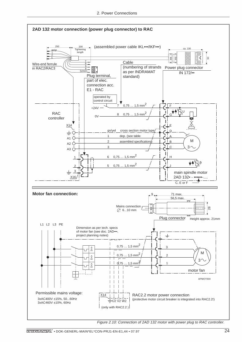
Figure 2.10: Connection of 2AD 132 motor with power plug to RAC controller.
APMOT004
Motor fan connection:
M
31
2
3
PE
0,75 … 1,5 mm2
0,75 … 1,5 mm2
Plug connector
7 0,75 … 1,5 mm2
8 0,75 … 1,5 mm2
6 0,75 … 1,5 mm2
5 0,75 … 1,5 mm2
gn/yel cross section motor type
1 dep. (see table
2 assembled specifications)
3
RACcontroller
2
3
1
A1
A2
A3
X14
X16
E
D
A
B
C
H
Jϑ
U
F
G0V
+24V
Wire-end ferrulein RAC2/RAC3
operated by control circuit
2AD 132 motor connection (power plug connector) to RAC
motor fan
M
3
L2L1
I>>
I>>
Dimension as per tech. specs of motor fan (see doc. 2AD•••, project planning notes)
I>> 0,75 … 1,5 mm2
L3
56,5 max.71 max.9
28
Height approx. 21mm
Plug terminal, part of elec. connection acc.E1 - RAC
Power plug connectorCable(numbering of strands as per INDRAMAT standard)
Schirm
7856
200ca. 130
50
Tightening length
IN 172/••
(assembled power cable IKL•••/IKF•••)ge/gr123
250
Permissible mains voltage:3xAC400V ±15%, 50...60Hz3xAC460V ±10%, 60Hz
RAC2.2 motor power connection(protective motor circuit breaker is integrated into RAC2.2!)
X14
U2 V2 W2
(only with RAC2.2 )
Mains connection 6...10 mm
main spindle motor 2AD 132• - ••••••-....C, E or F
2. Power Connections
25• DOK-GENERL-MAIN*EL*CON-PRJ1-EN-E1,44 • 07.97
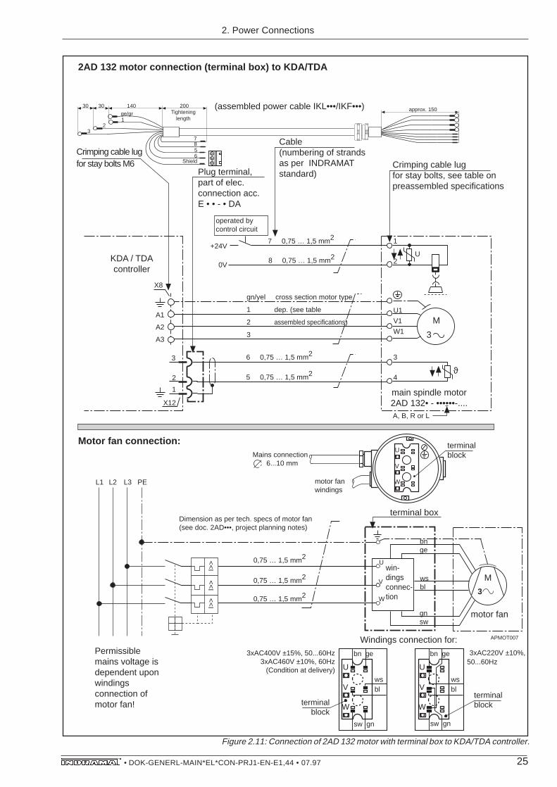
Figure 2.11: Connection of 2AD 132 motor with terminal box to KDA/TDA controller.
U
V
W
sw gn
bn ge
wsbl
APMOT007
Motor fan connection:
PE
0,75 … 1,5 mm2
0,75 … 1,5 mm2
terminal box
Permissible mains voltage is dependent upon windings connection of motor fan!
7 0,75 … 1,5 mm2
8 0,75 … 1,5 mm2
6 0,75 … 1,5 mm2
5 0,75 … 1,5 mm2
gn/yel cross section motor type
1 dep. (see table
2 assembled specifications)
3
KDA / TDAcontroller
2
1
3
A1
A2
A3
X8
X12
U1
V1
W1
3
4ϑ
U
1
20V
+24V
operated by control circuit
2AD 132 motor connection (terminal box) to KDA/TDA
motor fan
M
3
L2L1
I>>
I>>
Dimension as per tech. specs of motor fan (see doc. 2AD•••, project planning notes)
I>> 0,75 … 1,5 mm2
L3
Crimping cable lug for stay bolts M6
Plug terminal, part of elec. connection acc.E • • - • DA
Crimping cable lug for stay bolts, see table on preassembled specifications
Cable(numbering of strands as per INDRAMAT standard)
ge/gr
Shield
7856
12
3
200140approx. 150
3030Tightening
length
(assembled power cable IKL•••/IKF•••)
M
3
bnge
wsbl
gnsw
U
V
W
sw gn
bn ge
wsbl
3xAC400V ±15%, 50...60Hz3xAC460V ±10%, 60Hz
(Condition at delivery)
3xAC220V ±10%, 50...60Hz
terminal block
motor fanwindings
win-dings connec-tion
terminalblock
Windings connection for:
terminal block
Mains connection 6...10 mm
main spindle motor 2AD 132• - ••••••-....A, B, R or L
U
V
W
U
V
W
2. Power Connections

26• DOK-GENERL-MAIN*EL*CON-PRJ1-EN-E1,44 • 07.97
Figure 2.12: Connection of 2AD 132, 2AD 160, 2AD 180 and 2AD 200 motors(all have terminal box)
APMOT008
Motor fan connection:
PE
0,75 … 1,5 mm2
0,75 … 1,5 mm2
Motor fan windings
Permissible mains voltage:
7 0,75 … 1,5 mm2
8 0,75 … 1,5 mm2
6 0,75 … 1,5 mm2
5 0,75 … 1,5 mm2
gn/yel cross section motor type
1 dep. (see table
2 assembled specifications)
3
RACcontroller
2
1
3
A1
A2
A3
X14
X16
U1
V1
W1
3
4ϑ
U
1
20V
+24V
operated by control circuit
2AD 160, 2AD 180, 2AD 200 2AD 132 • - • • • • • • - . . .
2AD 132 motor connection (terminal box), 2AD 160, 2AD 180 and 2AD 200 to RAC
motor fan
M
3
L2L1
I>>
I>>
Dimension of the motor protective switch as per tech. specs on motor fan (see doc. 2AD•••, project planning notes)
I>> 0,75 … 1,5 mm2
L3
Plug terminal, part of elec. connection acc.E1-RAC
Crimping cable lug for stay bolts, see table for assembled specifications
Cable(numbering of strands as per INDRAMAT standard)
Shield
7856
200approx. 150Tightening
length
(assembled power cable IKL•••/IKF•••)
M
3
3xAC400V ±15%, 50...60Hz3xAC460V ±10%, 60Hz
Motor fanwindings
terminalblock
Wire-end ferrulein RAC2/RAC3
ge/gr123
250
RAC2.2 motor fan connection(protective motor switch is integrated into RAC 2.2!)
X14
U2 V2 W2
(only with RAC2.2)
Mains connection 6...10 mm
U
V
W
U
V
W
A, B, R or L
2. Power Connections

27• DOK-GENERL-MAIN*EL*CON-PRJ1-EN-E1,44 • 07.97
Figure 2.14: Connection of 1MB frameless spindle motors to KDA/TDAcontrollers via power plug connectors.
APMOT012
6 0,75 … 1,5 mm2
5 0,75 … 1,5 mm2
gn/yel cross section motor type
1 dep. (see table
2 assembled specifications)
3
KDA / TDAconnector
2
1
3
A1
A2
A3
X8
X12
E
D
A
B
C
H
Jϑ
F
G
1MBframeless spindle motor
1MB motor connection (power plug connector) to KDA/TDA
M
3
Crimping cable lugfor stay bolts M6
Plug terminal, part of elec. connection acc.E • • - • DA
Power plug connectorCable(numbering of strands as per INDRAMAT standard)
ge/gr
Shield
7856
12
3
200140ca. 130
503030
Tightening length
IN 172/••
(assembled power cable IKL•••/IKF•••) 25 20
FlangeconnectorIN 192/••
ϑ
(Substitute NTC-resistor, function not guaranteed!)
Fig. 2.13: Connection via terminal box of 1MB frameless spindle motors to KDA/TDA controllers
Motor connection 1MB (terminal box) to KDA/TDA
Cable(numbering of cores ad per INDRAMAT standard)
Shield
7856
200approx. 150Tightening
length
(assembled power cable IKL•••/IKF•••)
6 0,75 … 1,5 mm2
5 0,75 … 1,5 mm2
gn/yel cross section motor type
1 dep. (see table
2 assembled specifications)
3
U1V1W1
ϑ
1MBframeless spindle motor
M
3
apmot009
0,75...1,5 mm2
0,75...1,5 mm2
Terminal box
ϑ
(Substitute NTC-resistor,function not guaranteed!)KDA / TDA
controller
2
1
3
A1
A2
A3
X8
X12
Crimping cable lugfor stay bolts M6
ge/gr1
23
1403030
Plug terminal, part of elec. connection acc.E • • - • DA
Crimping cable lugs forstay bolts, see table
assembled specs
2. Power Connections

28• DOK-GENERL-MAIN*EL*CON-PRJ1-EN-E1,44 • 07.97
Fig. 2.16: 1MB frameless spindle motor connection to RAC controller via powerplug connector.
1MB motor connection (terminal box) to RAC
Plug terminal, part of elec. connection acc.E 1-RAC
Cable(numbering of strands as per INDRAMAT standard)
Shield
7856
200approx. 150Tightening
length
(assembled power cable IKL•••/IKF•••)
6 0,75 … 1,5 mm2
5 0,75 … 1,5 mm2
gn/yel cross section motor type
1 dep. (see table
2 assembled specifications)
3
U1V1W1
ϑ
1MBframeless spindle motor
M
3
apmot010
0,75...1,5 mm2
0,75...1,5 mm2
terminal box
ϑ
(Substitute NTC-resistor, function not guaranteed!)
Wire-end ferrulein RAC2/RAC3
RACcontroller
2
3
1
A1
A2
A3
X14
X16
ge/gr12
200
3
Crimping cable lug forstay bolts, see table forassembled specifications
APMOT011
6 0,75 … 1,5 mm2
5 0,75 … 1,5 mm2
gn/yel cross section motor type
1 dep. (see table
2 assembled specifications)
3
E
D
A
B
C
H
Jϑ
F
G
1MB frameless spindle motor
1MB motor connection (terminal box) to RAC
M
3
Plug terminal, part of elec. connection acc.E • • - • DA
Power plug connectorCable(numbering of strands as per INDRAMAT standard)
Shield
7856
200approx. 130
50Tightening
length
IN 172/••
(assembled power cable IKL•••/IKF•••) 25 20
FlangeconnectorIN 192/••
ϑ
(Substitute NTC-resistor, function not guaranteed!)
Wire-end ferrulein RAC2/RAC3
RACcontroller
2
3
1
A1
A2
A3
X14
X16
ge/gr12
200
3
Fig. 2.15: Connection via terminal box of 1MB frameless spindle motor to RACcontroller
2. Power Connections

29• DOK-GENERL-MAIN*EL*CON-PRJ1-EN-E1,44 • 07.97
2.1.3. AssembledData List
Figure 2.17: Four types of assembled power connections
The four types of power motor-controller connections are motor-typedependent and have been summarized in a table.
AssembledSpecifications Table
....direct connection + intermediate terminal
....plug design
....plugin testing points
Table listing assembled specifications for...
....direct connection + intermediate terminal
....plug design
....plugin testing points
Table listing assembled specifications for...
2AD main spindle motor
ZuordTab
frameless spindle motor 1MB
Figure 2.18: Allocation of main spindle motors in table
The tables list the available flexible and highly flexible assembledcables and their significant components.
direct with intermediate terminal plug withplugin
at terminal strip design testing points
Types of power connectionsmotor-controller
2. Power Connections

30• DOK-GENERL-MAIN*EL*CON-PRJ1-EN-E1,44 • 07.97
Figure 2.19: Assembled specifications table for direct connection andintermediate terminals on terminal strips for 2AD motors - Section 1.
Cab
leA
ssem
bled
cab
les
Ass
embl
ed c
able
com
pone
nts
for
dire
ct
conn
ectio
nA
ssem
bled
cab
les
for
inte
rmed
iate
cros
sfo
r di
rect
con
nect
ion
term
inal
s on
term
inal
str
ips
sect
ion
on th
e m
otor
Cab
leon
the
on th
e m
otor
on th
e co
ntro
ller
A [m
m ]
flex.
/hig
hly
flex.
cont
rolle
rfle
x./h
ighl
y fle
x.fle
x./h
ighl
y fle
x.
2AD
100B
-B··
···-
AS
·3-·
···
4IK
L071
/IKF
071
IN17
2/25
IN20
3/IN
403
...st
ay b
olt
M6
IKL0
74/
*)
not a
vaila
ble
(KD
A /T
DA
)
2AD
100C
-B··
···-
AS
·3-·
···
4IK
L071
/IKF
071
IN17
2/25
IN20
3/IN
403
...st
ay b
olt
M6
IKL0
74/
*)
not a
vaila
ble
(KD
A /T
DA
)
2AD
100D
-B··
···-
AS
·3-·
···
6IK
L112
/IKF
112
IN17
2/06
IN20
4/IN
404
...st
ay b
olt
M6
IKL1
15/
*)
not a
vaila
ble
(KD
A /T
DA
)
2AD
101D
-B··
···-
BD
·3-·
···
10IK
L130
/IKF
130
IN17
2/10
IN20
5/IN
405
...st
ay b
olt
M6
IKL1
34/
*)
not a
vaila
ble
(KD
A /T
DA
)
2AD
132B
-B··
···-
BS
·3-·
····
10IK
L130
/IKF
130
IN17
2/10
IN20
5/IN
405
...st
ay b
olt
M6
IKL1
34/
*)
not a
vaila
ble
(KD
A /T
DA
)
2AD
132C
-B··
···-
BS
·3-·
····
16*)
IN17
2/16
IN20
6/IN
406
...st
ay b
olt
M6
IKL1
50/IK
F15
0no
t ava
ilabl
e
(KD
A /T
DA
)
2AD
132D
-B··
···-
BD
·3-·
····
25IK
L170
/IKF
170
IN17
2/25
IN20
7/IN
407
...st
ay b
olt
M6
*)no
t ava
ilabl
e
(KD
A /T
DA
)
2AD
132B
-B··
···-
DS
·3-·
····
6IK
L115
/ *
)IN
172/
06IN
204/
IN40
4...
line-
up te
rmin
als
IKL1
15/
*)
not a
vaila
ble
(RA
C2
/RA
C3)
2AD
132C
-B··
···-
CS
·3-·
····
10IK
L134
/ *
)IN
172/
10IN
205/
IN40
5IK
L134
/ *
)no
t ava
ilabl
e
2AD
132D
-B··
···-
AS
·3-·
····
16IK
L150
/IKF
150
IN17
2/16
IN20
6/IN
406
IKL1
50/IK
F15
0no
t ava
ilabl
e
For
...
For
...
...lin
e-up
term
inal
s
(RA
C2
/RA
C3)
...lin
e-up
term
inal
s
(RA
C2
/RA
C3)
flex.
/hig
hly
flex.
alka
b01
2
Pow
er p
lug
conn
ecto
r (p
lug)
Sym
bols
:
Wire
-end
ferr
ule
Crim
ping
cab
le lu
gF
lang
e co
nnec
tion
Pow
er p
lug
conn
ecto
r (c
oupl
ing)
PG
scr
ew c
onne
ctio
n
*) A
vaila
ble.
For
inqu
iries
on
type
info
rmat
ion
cont
act D
evel
opm
ent D
ept.,
IND
RA
MA
T.
Sec
tion
1: 2
AD
pow
er c
onne
ctio
ns -
dire
ct c
onne
ctio
ns a
nd in
term
edia
te te
rmin
als
2. Power Connections

31• DOK-GENERL-MAIN*EL*CON-PRJ1-EN-E1,44 • 07.97
Figure 2.20: Assembled specifications table for direct connections andintermediate terminals on terminal strips for 2AD motors - Section 2.
Sec
tion
2: 2
AD
pow
er c
onne
ctio
ns -
dire
ct c
onne
ctio
ns a
nd in
term
edia
te te
rmin
als
2. Power Connections
Cab
leA
ssem
bled
cab
les
Cab
le c
ompo
nent
s fo
r di
rect
con
nect
ion
Ass
embl
ed c
able
s fo
r in
term
edia
tecr
oss
for
dire
ct c
onne
ctio
nte
rmin
als
on te
rmin
al s
trip
sse
ctio
non
the
mot
orC
able
on th
eon
the
mot
oron
the
cont
rolle
rA
[mm
]fle
x./h
ighl
y fle
x.co
ntro
ller
flex.
/hig
hly
flex.
flex.
/hig
hly
flex.
6IK
L110
..sta
y bo
lt M
6IN
204/
IN40
4...
line-
up te
rmin
als
*)
(RA
C2
/RA
C3)
IKL1
36/IK
F13
6IN
205/
IN40
5IK
L136
/IKF
136
2AD
132D
-B··
···-
AS
·3-·
···
IKL1
51/IK
F15
1IN
206/
IN40
6
2AD
160B
-B··
···-
BS
·3-·
···
IKL1
71/IK
F17
1IN
207/
IN40
7
2AD
160C
-B··
···-
BS
·3-·
····
IKL1
82/
*)IK
L182
/ *)
2AD
180C
-B··
···-
BS
·3-·
····
(PG
42)
2AD
180D
-B··
···-
BS
·3-·
····
50IK
L 19
1/ *
)IN
268/
*)
...S
crew
s*)
(PG
42
)M
12 (
RA
C4)
2AD
200C
-B··
···-
AS
·3-·
····
2 x
252
x IN
207/
2 x
IN 4
07
(PG
48)
2AD
132B
-B··
···-
DS
·3-·
····
(PG
29)
2AD
132C
-B··
···-
CS
·3-·
····
(PG
29)
(PG
29)
10 16 25 35 35IK
L182
/ *)
ALK
AB
02
2 x
IKL
175/
2 x
IKF
175
(PG
42)
(PG
29)
For
...
...lin
e-up
term
inal
s
(RA
C2
/RA
C3)
...lin
e-up
term
inal
s
(RA
C2
/RA
C3)
...lin
e-up
term
inal
s
(RA
C2
/RA
C3)
...lin
e-up
term
inal
s
(RA
C2
/RA
C3)
...lin
e-up
term
inal
s
(RA
C2
/RA
C3)
M8
..sta
y bo
lt M
6
M8
..sta
y bo
lt M
8
M8
..sta
y bo
lt M
8
M8
..sta
y bo
lt M
10
M10
..sta
y bo
lt M
10M
10
IKL1
51/IK
F15
1
IKL1
71/IK
F17
1
IKL1
82/
*)
*)...
Scr
ews
M12
(R
AC
4)
..sta
y bo
lt M
10M
10
..sta
y bo
lt M
12M
12
IN26
7
IN26
7
2AD
132B
-B··
···-
BS
·3-·
····
10IK
L135
/IKF
135
IN20
5/IN
405
..sta
y bo
lt M
6IK
L136
/IKF
136
not
avai
labl
e(P
G 2
9)(K
DA
/TD
A)
2AD
132C
-B··
···-
BS
·3-·
····
16IK
L157
/IKF
157
IN20
6/IN
406
..sta
y bo
lt M
6IK
L152
/IKF
152
(PG
29)
(KD
A /T
DA
)
2AD
132D
-B··
···-
BD
·3-·
····
25IK
L174
/IKF
174
IN20
7/IN
407
..sta
y bo
lt M
6IK
L172
/IKF
172
(PG
29)
(KD
A /T
DA
)
Für
... F
or...
..sta
y bo
lt M
6
M8
..sta
y bo
lt M
6
M8
..sta
y bo
lt M
8
M8
2
For
...
not
avai
labl
e
not
avai
labl
e
not
avai
labl
e
not
avai
labl
e
not
avai
labl
e
not
avai
labl
e
not
avai
labl
e
not
avai
labl
e
not
avai
labl
e
not
avai
labl
e
Pow
er p
lug
conn
ecto
r (p
lug)
Sym
bols
:
Wire
-end
ferr
ule
Crim
ping
cab
lelu
gF
lang
e co
nnec
tion
Pow
er p
lug
conn
ecto
r (c
oupl
ing)
PG
scr
ew c
onne
ctio
n*)
Ava
ilabl
e. F
or in
quiri
es o
n ty
pe in
form
atio
n
con
tact
Dev
elop
men
t Dep
t., IN
DR
AM
AT.
For
... F
or...
32• DOK-GENERL-MAIN*EL*CON-PRJ1-EN-E1,44 • 07.97
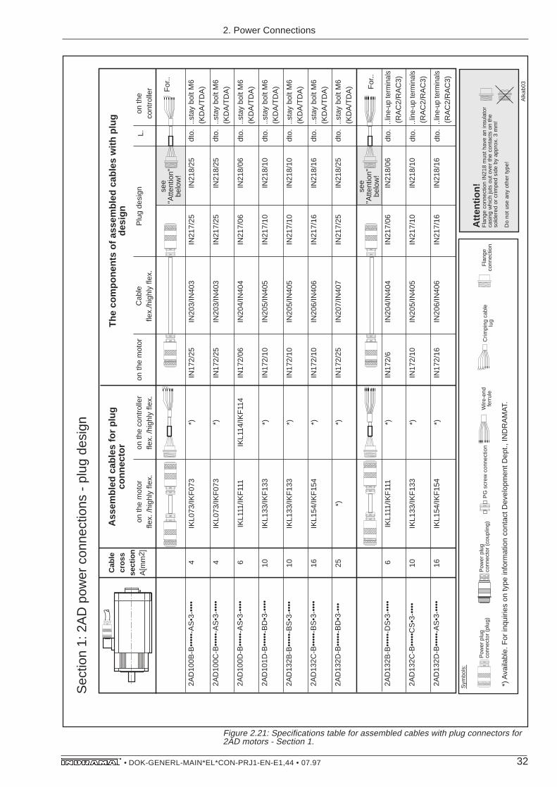
Figure 2.21: Specifications table for assembled cables with plug connectors for2AD motors - Section 1.
2AD
100B
-B••
•••-
AS
•3-•
•••
4IK
L073
/IKF
073
IN17
2/25
IN20
3/IN
403
IN21
7/25
IN21
8/25
2AD
100C
-B••
•••-
AS
•3-•
•••
4IK
L073
/IKF
073
IN17
2/25
IN20
3/IN
403
IN21
7/25
IN21
8/25
2AD
100D
-B••
•••-
AS
•3-•
•••
6IK
L111
/IKF
111
IKL1
14/IK
F11
4IN
172/
06IN
204/
IN40
4IN
217/
06IN
218/
06
2AD
101D
-B••
•••-
BD
•3-•
•••
10IK
L133
/IKF
133
IN17
2/10
IN20
5/IN
405
IN21
7/10
IN21
8/10
2AD
132B
-B••
•••-
BS
•3-•
•••
10IK
L133
/IKF
133
IN17
2/10
IN20
5/IN
405
IN21
7/10
IN21
8/10
2AD
132C
-B••
•••-
BS
•3-•
•••
16IK
L154
/IKF
154
IN17
2/10
IN20
6/IN
406
IN21
7/16
IN21
8/16
2AD
132D
-B••
•••-
BD
•3-•
••25
*)IN
172/
25IN
207/
IN40
7IN
217/
25IN
218/
25
2AD
132B
-B••
•••-
DS
•3-•
•••
6IK
L111
/IKF
111
IN17
2/6
IN20
4/IN
404
IN21
7/06
IN21
8/06
2AD
132C
-B••
•••C
S•3
-•••
•10
IKL1
33/IK
F13
3IN
172/
10IN
205/
IN40
5IN
217/
10IN
218/
10
2AD
132D
-B••
•••-
AS
•3-•
•••
16IK
L154
/IKF
154
IN17
2/16
IN20
6/IN
406
IN21
7/16
IN21
8/16
Cab
lecr
oss
sect
ion
A[m
m2 ]
Ass
embl
ed c
able
s fo
r pl
ug
conn
ecto
r
on th
e m
otor
fle
x. /h
ighl
y fle
x.on
the
cont
rolle
r fle
x. /h
ighl
y fle
x.on
the
mot
orC
able
flex.
/hig
hly
flex.
Plu
g de
sign
L.on
the
cont
rolle
r
The
com
pone
nts
of a
ssem
bled
cab
les
with
plu
g de
sign
*) *) *) *) *) *) *)
For
..
For
..
..lin
e-up
term
inal
s(R
AC
2/R
AC
3)
.. lin
e-up
term
inal
s(R
AC
2/R
AC
3)
.. lin
e-up
term
inal
s(R
AC
2/R
AC
3)
..sta
y bo
lt M
6(K
DA
/TD
A)
..sta
y bo
lt M
6(K
DA
/TD
A)
..sta
y bo
lt M
6(K
DA
/TD
A)
..sta
y bo
lt M
6(K
DA
/TD
A)
..sta
y bo
lt M
6(K
DA
/TD
A)
dto.
dto.
dto.
dto.
dto.
dto.
dto.
dto.
*) *)
Alk
ab03
..sta
y bo
lt M
6(K
DA
/TD
A)
..sta
y bo
lt M
6(K
DA
/TD
A)
dto.
dto.
Pow
er p
lug
conn
ecto
r (p
lug)
Sym
bols
:
Wire
-end
fe
rrul
eC
rimpi
ng c
able
lug
Fla
nge
conn
ectio
n
Pow
er p
lug
conn
ecto
r (c
oupl
ing)
PG
scr
ew c
onne
ctio
n
*) A
vaila
ble.
For
inqu
iries
on
type
info
rmat
ion
cont
act D
evel
opm
ent D
ept.,
IND
RA
MA
T.
Atte
ntio
n!
Fla
nge
conn
ectio
n IN
218
mus
t hav
e an
insu
lato
r ca
sing
whi
ch ju
ts o
ut o
ver
the
cont
acts
on
the
sold
ered
or
crim
ped
side
by
appr
ox. 3
mm
!
Do
not u
se a
ny o
ther
type
!
see
"Atte
ntio
n"be
low
!
see
"Atte
ntio
n"be
low
!
Sec
tion
1: 2
AD
pow
er c
onne
ctio
ns -
plu
g de
sign
2. Power Connections

33• DOK-GENERL-MAIN*EL*CON-PRJ1-EN-E1,44 • 07.97
Figure 2.22: Specifications for connection with plug design for 2AD motors-Section2.
2A
D1
32
B-B
•••.
•-D
S•3
-•••
•6
IN2
04
/IN
40
4
IN2
17
/10
IN2
18
/10
2A
D1
32
C-B
•••.
•-C
S•3
-•••
•1
0
IN2
06
/IN
40
6
no
t a
vaila
ble
IN2
18
/16
2A
D1
32
D-B
•••.
•-A
S•3
-•••
16
IN2
07
/IN
40
7
no
t a
vaila
ble
IN2
18
/25
2A
D1
60
B-B
•••.
•-B
S•3
-•••
•2
5
IN2
05
/IN
40
5
IN2
18
/06
2A
D1
60
C-B
•••.
•-B
S•3
-•••
•3
5
2A
D1
80
C-B
•••.
•-B
S•3
-•••
•3
5
IN2
17
/06
2A
D1
80
D-B
•••.
•-B
S•3
-•••
•5
0
2A
D2
00
C-B
•••.
•AS
•3-•
•••
2X
25
Cab
lecr
oss
sect
ion
A[m
m]
(PG
29
)
(PG
42
)
(PG
42
)
Ass
embl
ed c
able
s fo
r pl
ug
conn
ecto
r
on
th
e m
oto
r fle
x. /h
igh
ly fle
x.o
n th
e c
on
tro
ller
flex.
/h
igh
ly fle
x.o
n th
e m
oto
rC
ab
lefle
x./h
igh
ly fle
x.p
lug
de
sig
nL
.o
n th
e
con
tro
ller
Ass
embl
ed c
able
com
pone
nts
with
pl
ug c
onne
ctor
(PG
48
)
(PG
42
)n
ot a
vaila
ble
no
t a
vaila
ble
Fo
r..
..sc
rew
sM
12
(RA
C4
)
..lin
e-up
term
inal
s(R
AC
2/R
AC
3)
dto
.
dto
.
dto
.
dto
.
dto
.
dto
.
dto
.
dto
.
..st
ay
bo
lt M
8
M8
Fo
r..
AL
KA
B0
4
(PG
29
)
(PG
29
)
(PG
29
)
no
t a
vaila
ble
no
t a
vaila
ble
..st
ay
bo
lt M
8
M8
..st
ay
bo
lt M
6
M8
..st
ay
bo
lt M
6
M8
..st
ay
bo
lt M
10
M1
0
..st
ay
bo
lt M
10
M1
0
..st
ay
bo
lt M
10
M1
0
..st
ay
bo
lt M
12
M1
2
..lin
e-up
term
inal
s(R
AC
2/R
AC
3)
..lin
e-up
term
inal
s(R
AC
2/R
AC
3)
..lin
e-up
term
inal
s(R
AC
2/R
AC
3)
..lin
e-up
term
inal
s(R
AC
2/R
AC
3)
..lin
e-up
term
inal
s(R
AC
2/R
AC
3)
..sc
rew
sM
12
(RA
C4
)
2A
D1
32
B-B
•••.
•-B
S•3
-•••
•1
0IN
20
5/IN
40
5IN
21
7/1
0IN
21
8/1
0
2A
D1
32
C-B
•••.
•-B
S•3
-•••
•1
6IN
20
6/IN
40
6IN
21
7/1
6IN
21
8/1
6
2A
D1
32
D-B
•••.
•-B
D•3
-•••
•2
5IN
20
7/IN
40
7IN
21
7/2
5IN
21
8/2
5
(PG
29
)
(PG
29
)
(PG
29
)
*)
Fo
r..
..st
ay
bo
lt M
6(K
DA
/TD
A)
..st
ay
bo
lt M
6(K
DA
/TD
A)
..st
ay
bo
lt M
6(K
DA
/TD
A)
dto
.
dto
.
dto
.
..st
ay
bo
lt M
6
M8
..st
ay
bo
lt M
8
M8
..st
ay
bo
lt M
8
M8
Fo
r..
*) *) *)IN
21
7/2
5
IN2
17
/16
no
t a
vaila
ble
no
t a
vaila
ble
no
t a
vaila
ble
no
t a
vaila
ble
no
t a
vaila
ble
no
t a
vaila
ble
*) *) *)
*)
IKL
13
7/IK
F1
37
no
t a
vaila
ble
no
t a
vaila
ble
*) *)
no
t a
vaila
ble
no
t a
vaila
ble
IKL
13
7/IK
F1
37
IKL
15
3/IK
F1
53
IKL
17
3/IK
F1
73
Po
we
r p
lug
co
nn
ect
or
(plu
g)
Sym
bo
ls:
Wire
-en
d
ferr
ule
Crim
pin
g c
ab
lelu
gF
lan
ge
co
nn
ect
ion
Po
we
r p
lug
co
nn
ect
or
(co
up
ling
)P
G s
cre
w c
on
ne
ctio
n
*) A
vaila
ble
. F
or
inq
uirie
s o
n typ
e in
form
atio
n c
on
tact
De
velo
pm
en
t D
ep
t., IN
DR
AM
AT.
see
"a
tte
ntio
n"
be
low
!
see
"a
tte
ntio
n"
be
low
!
see
"a
tte
ntio
n"
be
low
!
Fo
r..
Fo
r..
IN2
67
IN2
67
IN2
68
2 x
IN
20
7/2
x IN
40
7
Atte
ntio
n!
Fla
ng
e c
on
ne
ctio
n I
N2
18
mu
st h
ave
an
insu
lato
r ca
sin
g w
hic
h ju
ts o
ut
ove
r th
e c
on
tact
s o
n t
he
so
lde
red
or
crim
pe
d s
ide
by
ap
pro
x. 3
mm
!
Do
no
t u
se a
ny
oth
er
typ
e!
2
Sec
tion
2: 2
AD
pow
er c
onne
ctio
ns -
plu
g de
sign
2. Power Connections

34• DOK-GENERL-MAIN*EL*CON-PRJ1-EN-E1,44 • 07.97
Figure 2.23: Table of assembled specifications for connections with plug testingpoints in 2AD motors - Section 1.
2AD
100B
-B••
•••-
AS
•3-•
•••
4IK
L072
/IKF
072
IN17
2/25
IN20
3/IN
403
IN21
0/25
IN17
2/25
2AD
100C
-B••
•••-
AS
•3-•
•••
4IN
172/
25IN
203/
IN40
3IN
210/
25IN
172/
25
2AD
100D
-B••
•••-
AS
•3-•
•••
6IK
L113
/IKF
113
IKL1
12/IK
F11
2IN
172/
06IN
204/
IN40
4IN
210/
06IN
172/
06
2AD
101D
-B••
•••-
BD
•3-•
•••
10IK
L138
/IKF
138
IN17
2/10
IN20
5/IN
405
IN21
0/10
IN17
2/10
2AD
132B
-B••
•••-
BS
•3-•
•••
10IK
L138
/IKF
138
IN17
2/10
IN20
5/IN
405
IN21
0/10
IN17
2/10
2AD
132C
-B••
•••-
BS
•3-•
•••
16IK
L158
/IKF
158
IN17
2/10
IN20
6/IN
406
IN21
0/16
IN17
2/16
2AD
132D
-B••
•••-
BD
•3-•
••25
IKL1
78/IK
F17
8IN
172/
25IN
207/
IN40
7IN
210/
25IN
172/
25
2AD
132B
-B••
•••-
DS
•3-•
•••
6IK
L113
/IKF
113
IN17
2/6
IN20
4/IN
404
IN21
0/06
IN17
2/06
2AD
132C
-B••
•••-
CS
•3-•
•••
10IK
L138
/IKF
138
IN17
2/10
IN20
5/IN
405
IN21
0/10
IN17
2/10
2AD
132D
-B••
•••-
AS
•3-•
•••
16IK
L158
/IKF
158
IN17
2/16
IN20
6/IN
406
IN21
0/16
IN17
2/16
*)
IKL1
34/
*)
*)
For
..
For
..
..lin
e-up
term
inal
s(R
AC
2/R
AC
3)
..lin
e-up
term
inal
s(R
AC
2/R
AC
3)
..lin
e-up
term
inal
s(R
AC
2/R
AC
3)
..sta
y bo
lt M
6(K
DA
/TD
A)
..sta
y bo
lt M
6(K
DA
/TD
A)
..sta
y bo
lt M
6(K
DA
/TD
A)
..sta
y bo
lt M
6(K
DA
/TD
A)
..sta
y bo
lt M
6(K
DA
/TD
A)
dto.
dto.
dto.
dto.
dto.
dto.
dto.
dto.
ALK
AB
05
IKL0
72/IK
F07
2
IKL0
71/IK
F07
1
IKL0
71/IK
F07
1
IKL1
30/IK
F13
0
IKL1
30/IK
F13
0
*)
IKL1
70/IK
F17
0
Cab
lecr
oss
sect
ion
A[m
m2 ]
Pre
asse
mbl
ed c
able
s fo
r pl
ugin
te
stin
g po
ints
on th
e m
otor
fle
x. /h
ighl
y fle
x.on
the
cont
rolle
r fle
x. /h
ighl
y fle
x.on
the
mot
orC
able
flex.
/hig
hly
flex.
plug
in te
stin
g po
ints
L.on
the
cont
rolle
r
Com
pone
nts
of p
reas
sem
bled
cab
les
with
plu
gin
test
ing
poin
ts
Pow
er p
lug
conn
ecto
r (p
lug)
Sym
bols
:
Mul
ti-co
re
cabl
e en
dC
ompr
essi
on
cabl
e sh
oeF
lang
e co
nnec
tion
Pow
er p
lug
conn
ecto
r (c
oupl
ing)
PG
scr
ew c
onne
ctio
n
*) A
vaila
ble.
For
inqu
iries
on
type
info
rmat
ion
cont
act D
evel
opm
ent D
ept.,
IND
RA
MA
T.
..sta
y bo
lt M
6(K
DA
/TD
A)
..sta
y bo
lt M
6(K
DA
/TD
A)
dto.
dto.
Sec
tion
1: 2
AD
pow
er c
onne
ctio
ns -
plu
gin
test
ing
poin
ts
2. Power Connections

35• DOK-GENERL-MAIN*EL*CON-PRJ1-EN-E1,44 • 07.97
Figure 2.24: Table of assembled specifications for connections with plugintesting points in 2AD motors - Section 2.
IN1
72
/06
IN2
17
/06
..lin
e-up
term
inal
s(R
AC
2/R
AC
3)
dto
.2
AD
13
2B
-B••
•••-
DS
•3-•
•••
6*)
IN2
04
/IN
40
4
IN2
17
/10
IN1
72
/10
2A
D1
32
C-B
••••
•-C
S•3
-•••
•1
0IK
L1
29
/IK
F1
29
IN2
06
/IN
40
6IN
21
7/1
6IN
17
2/1
62
AD
13
2D
-B••
•••-
AS
•3-•
••1
6
IN2
07
/IN
40
7IN
21
7/2
5IN
17
2/2
52
AD
16
0B
-B••
•••-
BS
•3-•
•••
25
IN2
05
/IN
40
5
2A
D1
60
C-B
••••
•-B
S•3
-•••
•3
5
2A
D1
80
C-B
••••
•-B
S•3
-•••
•3
5
2A
D1
80
D-B
••••
•-B
S•3
-•••
•5
0n
ot
ava
ilab
le
2A
D2
00
C-B
••••
•AS
•3-•
•••
2X
25
no
t a
vaila
ble
(PG
29
)
(PG
42
)
(PG
42
)
(PG
48
)
(PG
42
)n
ot
ava
ilab
le
no
t a
vaila
ble
Fo
r..
Fo
r..
..S
cre
ws
M1
2(R
AC
4)
dto
.
dto
.
dto
.
dto
.
dto
.
dto
.
dto
.
..st
ay
bo
lt M
8
M8
Fo
r..
AL
KA
B0
6
IKL
13
4/
*)
(PG
29
)
(PG
29
)
(PG
29
)
IKL
14
9/I
KF
14
9
IKL
16
9/I
KF
16
9
no
t a
vaila
ble
no
t a
vaila
ble
*) *) *)
no
t a
vaila
ble
no
t a
vaila
ble
..st
ay
bo
lt M
8
M8
..st
ay
bo
lt M
6
M8
..st
ay
bo
lt M
6
M8
Fo
r..
..st
ay
bo
lt M
10
M1
0
..st
ay
bo
lt M
10
M1
0
IN2
67
IN2
67
..st
ay
bo
lt M
10
M1
0
..st
ay
bo
lt M
12
M1
2
..lin
e-up
term
inal
s
(RA
C2
/RA
C3
)
..lin
e-up
term
inal
s(R
AC
2/R
AC
3)
..lin
e-up
term
inal
s(R
AC
2/R
AC
3)
..lin
e-up
term
inal
s(R
AC
2/R
AC
3)
..lin
e-up
term
inal
s(R
AC
2/R
AC
3)
..S
cre
ws
M1
2(R
AC
4)
2A
D1
32
B-B
••••
•-B
S•3
-•••
•1
0IK
L1
29
/IK
F1
29
IN2
05
/IN
40
5IN
21
0/1
0IN
17
2/1
0
2A
D1
32
C-B
••••
•-B
S•3
-•••
•1
6IK
L1
49
/IK
F1
49
IN2
06
/IN
40
6IN
21
0/1
6IN
17
2/1
6
2A
D1
32
D-B
••••
•-B
D•3
-•••
•2
5IK
L1
69
/IK
F1
69
IN2
07
/IN
40
7IN
21
0/2
5IN
17
2/2
5
(PG
29
)
(PG
29
)
(PG
29
)
Fo
r..
..st
ay
bo
lt M
6(K
DA
/TD
A)
..st
ay
bo
lt M
6(K
DA
/TD
A)
..st
ay
bo
lt M
6(K
DA
/TD
A)
dto
.
dto
.
dto
.
..st
ay
bo
lt M
6
M8
..st
ay
bo
lt M
8
M8
..st
ay
bo
lt M
8
M8
Fo
r..
IKL
13
0/I
KF
13
0
*)
IKL
17
0/I
KF
17
0
Po
we
r p
lug
co
nn
ect
or
(plu
g)
Sym
bo
ls:
Mu
lti-c
ore
ca
ble
en
dC
om
pre
ssio
n
cab
le s
ho
es
Fla
ng
e
con
ne
ctio
n
Po
we
r p
lug
co
nn
ect
or
(co
up
ling
)P
G s
cre
w c
on
ne
ctio
n
*) A
vaila
ble
. F
or
inq
uirie
s o
n t
ype
info
rma
tion
co
nta
ct D
eve
lop
me
nt
De
pt.
, IN
DR
AM
AT.
Ca
ble
cro
ssse
ctio
nA
[mm
2]
Pre
ass
em
ble
d c
ab
le f
or
plu
gin
te
stin
g p
oin
ts
on
th
e m
oto
r fle
x. /
hig
hly
fle
x.o
n t
he
co
ntr
olle
r fle
x. /
hig
hly
fle
x.o
n t
he
mo
tor
Ca
ble
flex.
/h
igh
ly f
lex.
plu
gin
te
stin
g p
oin
tsL
.o
n t
he
co
ntr
olle
r
Co
mp
on
en
ts o
f p
rea
sse
mb
led
ca
ble
s w
ith p
lug
in
test
ing
po
ints
no
t a
vaila
ble
no
t a
vaila
ble
no
t a
vaila
ble
no
t a
vaila
ble
no
t a
vaila
ble
no
t a
vaila
ble
no
t a
vaila
ble
no
t a
vaila
ble
IN2
68
2 x
IN
20
7/2
x I
N 4
07
Sec
tion
2: 2
AD
pow
er c
onne
ctio
ns -
plu
gin
test
ing
poin
ts
2. Power Connections

36• DOK-GENERL-MAIN*EL*CON-PRJ1-EN-E1,44 • 07.97
Figure 2.25: Table of assembled specifications for direct connection and forintermediate terminals on terminals strips in 1MB motors - Section 1.
Sec
tion
1: 1
MB
pow
er c
onne
ctio
ns -
plu
gin
test
ing
poin
ts
Cab
leA
ssem
bled
cab
les
Com
pone
nts
of a
ssem
bled
cab
les
for
dire
ct
conn
ectio
nsA
ssem
bled
cab
les
for
inte
rmed
iate
cros
sfo
r di
rect
con
nect
ion
term
inal
s on
term
inal
str
ips
sect
ion
on th
e m
otor
Cab
leon
the
on th
e m
otor
on th
e co
ntro
ller
A [m
m ]
flex.
/hig
hly
flex.
cont
rolle
rfle
x./h
ighl
y fle
x.fle
x./h
ighl
y fle
x.
ALK
AB
07
2
Pow
er p
lug
conn
ecto
r (p
lug)
Sym
bols
:
Wire
-end
fe
rrul
eC
rimpi
ng c
able
lu
gF
lang
e co
nnec
tion
Pow
er p
lug
conn
ecto
r (c
oupl
ing)
PG
scr
ew c
onne
ctio
n
*) A
vaila
ble.
For
inqu
iries
on
type
info
rmat
ion
cont
act D
evel
opm
ent D
ept.,
IND
RA
MA
T.
1MB
160F
-4A
...25
IKL1
74/IK
F17
4IN
207/
IN40
7..s
tay
bolt
M6
IKL1
72/IK
F17
2
(PG
29)
(KD
A /T
DA
)
..sta
y bo
lt M
8
M8
not
avai
labl
e
1MB
200D
-4E
...25
IKL1
74/IK
F17
4IN
207/
IN40
7..s
tay
bolt
M6
IKL1
72/IK
F17
2
(PG
29)
(KD
A /T
DA
)
..sta
y bo
lt M
8
M8
not
avai
labl
e
1MB
240B
-4A
...10
IKL1
35/IK
F13
5IN
205/
IN40
5..s
tay
bolt
M6
IKL1
36/IK
F13
6no
tav
aila
ble
(PG
29)
(KD
A /T
DA
)
..sta
y bo
lt M
6
M8
1MB
240D
-4A
...10
IKL1
35/IK
F13
5IN
205/
IN40
5..s
tay
bolt
M6
IKL1
36/IK
F13
6no
tav
aila
ble
(PG
29)
(KD
A /T
DA
)
..sta
y bo
lt M
6
M8
1MB
240F
-4A
...25
IKL1
74/IK
F17
4IN
207/
IN40
7..s
tay
bolt
M6
IKL1
72/IK
F17
2
(PG
29)
(KD
A /T
DA
)
..sta
y bo
lt M
8
M8
not
avai
labl
e
1MB
240H
-4A
...25
IKL1
74/IK
F17
4IN
207/
IN40
7..s
tay
bolt
M6
IKL1
72/IK
F17
2
(PG
29)
(KD
A /T
DA
)
..sta
y bo
lt M
8
M8
not
avai
labl
e
1MB
241H
-6C
...25
IKL1
74/IK
F17
4IN
207/
IN40
7..s
tay
bolt
M6
IKL1
72/IK
F17
2
(PG
29)
(KD
A /T
DA
)
..sta
y bo
lt M
8
M8
not
avai
labl
e
1MB
160E
-4B
...
(PG
)
1MB
160B
-4A
...
(PG
29)
1MB
200D
-4C
...
(PG
)
1MB
310B
-6A
...
(PG
)
For
... F
or...
1MB
160D
-4A
...
(PG
29)
10IK
L135
/IKF
135
IN20
5/IN
405
..sta
y bo
lt M
6IK
L136
/IKF
136
not
avai
labl
e(K
DA
/TD
A)
..sta
y bo
lt M
6
M8
10IK
L135
/IKF
135
IN20
5/IN
405
..sta
y bo
lt M
6IK
L136
/IKF
136
not
avai
labl
e(K
DA
/TD
A)
..sta
y bo
lt M
6
M8
2. Power Connections

37• DOK-GENERL-MAIN*EL*CON-PRJ1-EN-E1,44 • 07.97
Ca
ble
Ass
em
ble
d c
ab
les
Co
mp
on
en
ts o
f th
e a
sse
mb
led
ca
ble
fo
r d
ire
ct c
on
ne
ctio
nA
sse
mb
led
ca
ble
s fo
r in
term
ed
iate
cro
ssfo
r d
ire
ct c
on
ne
ctio
nte
rmin
als
on
te
rmin
al s
trip
sse
ctio
no
n t
he
m
oto
rC
ab
leo
n t
he
on
th
e m
oto
ro
n t
he
co
ntr
olle
rA
[m
m ]
flex.
/hig
hly
fle
x.co
ntr
olle
rfle
x./h
igh
ly f
lex.
flex.
/hig
hly
fle
x.
AL
KA
B0
8
2
Po
we
r p
lug
co
nn
ect
or
(plu
g)
Sym
bo
ls:
Wire
-en
d
ferr
ule
Crim
pin
g c
ab
lelu
gF
lan
ge
co
nn
ect
ion
Po
we
r p
lug
co
nn
ect
or
(co
up
ling
)P
G s
cre
w c
on
ne
ctio
n
*) A
vaila
ble
. F
or
inq
uirie
s o
n t
ype
info
rma
tion
co
nta
ct D
eve
lop
me
nt
De
pt.
, IN
DR
AM
AT.
Fo
r...
Fo
r...
IKL
13
6/I
KF
13
6IN
20
5/I
N4
05
IKL
13
6/I
KF
13
6..
.lin
e-u
p t
erm
ina
ls
(RA
C2
/R
AC
3)
..st
ay
bo
lt M
6
M8
no
ta
vaila
ble
IKL
13
6/I
KF
13
6IN
20
5/I
N4
05
IKL
13
6/I
KF
13
6..
.lin
e-u
p t
erm
ina
ls
(RA
C2
/R
AC
3)
..st
ay
bo
lt M
6
M8
no
ta
vaila
ble
IKL
17
1/I
KF
17
1IN
20
7/I
N4
07
...li
ne
-up
te
rmin
als
(RA
C2
/R
AC
3)
..st
ay
bo
lt M
8
M8
IKL
17
1/I
KF
17
1n
ot
ava
ilab
le
IKL
18
2/
*)IN
26
7..
.lin
e-u
p t
erm
ina
ls
(RA
C2
/R
AC
3)
..st
ay
bo
lt M
10
M1
0
IKL
18
2/
*)n
ot
ava
ilab
le
IKL
15
1/I
KF
15
1IN
20
6/I
N4
06
...li
ne
-up
te
rmin
als
(RA
C2
/R
AC
3)
..st
ay
bo
lt M
8
M8
IKL
15
1/I
KF
15
1n
ot
ava
ilab
le
1M
B2
00
D-4
B..
.
(PG
29
)
10
1M
B2
41
H-6
D..
.
(PG
29
)
10
1M
B3
10
B-6
B..
.2
5
(PG
29
)
1M
B3
10
D-6
B..
.2
5
(PG
29
)
1M
B3
12
C-4
A..
.3
5(P
G 2
9)
1M
B1
60
F-4
B..
.
(PG
)
1M
B2
00
D-4
D..
.
(PG
)
1M
B2
00
E-4
B..
.
(PG
)
1M
B2
00
H-4
B..
.(P
G
)
1M
B2
40
F-4
B..
.
(PG
)
1M
B3
10
F-6
B..
.
(PG
42
)
1M
B3
12
B-4
A..
.
(PG
29
)
35
1M
B2
40
H-4
B..
.
(PG
29
)
16
1M
B F
ram
ele
ss S
pin
dle
Mo
tor
IKL
18
2/
*)
...li
ne
-up
te
rmin
als
(RA
C2
/R
AC
3)
..st
ay
bo
lt M
10
M1
0
IKL
18
2/
*)
IN2
67
no
ta
vaila
ble
IKL
17
1/I
KF
17
1IN
20
7/I
N4
07
...li
ne
-up
te
rmin
als
(RA
C2
/R
AC
3)
..st
ay
bo
lt M
8
M8
IKL
17
1/I
KF
17
1n
ot
ava
ilab
le
IKL
17
1/I
KF
17
1IN
20
7/I
N4
07
...li
ne
-up
te
rmin
als
(RA
C2
/R
AC
3)
..st
ay
bo
lt M
8
M8
IKL
17
1/I
KF
17
1n
ot
ava
ilab
le2
5
Sec
tion
2: 1
MB
pow
er c
onne
ctio
ns -
plu
gin
test
ing
poin
ts
2. Power Connections
Figure 2.26: Table of assembled specifications for direct connection and forintermediate terminals on terminals strips in 1MB motors - Section 2.

38• DOK-GENERL-MAIN*EL*CON-PRJ1-EN-E1,44 • 07.97
Figure 2.27: Table listing information on assembled cables for direct connectionsand for intermediate terminals on terminal strips in 1MB motors - Section 3.
Sec
tion
3: 1
MB
pow
er c
onne
ctio
ns -
dire
ct c
onne
ctio
ns a
nd in
term
edia
te te
rmin
als
Cab
leA
ssem
bled
cab
les
Com
pone
nts
of th
e as
sem
bled
cab
les
for
dire
ct c
onne
ctio
nsA
ssem
bled
cab
le fo
r in
term
edia
tecr
oss
for
dire
ct c
onne
ctio
nste
rmin
als
on te
rmin
al s
trip
sse
ctio
non
the
mot
orC
able
on th
eon
the
mot
oron
the
cont
rolle
rA
[mm
]fle
x./h
ighl
y fle
x.co
ntro
ller
flex.
/hig
hly
flex.
flex.
/hig
hly
flex.
ALK
AB
09
2
Pow
er p
lug
conn
ecto
r (p
lug)
Sym
bols
:
Wire
-end
fe
rrul
eC
rimpi
ng c
able
lug
Fla
nge
conn
ectio
n
Pow
er p
lug
conn
ecto
r (c
oupl
ing)
PG
scr
ew c
onne
ctio
n
*) A
vaila
ble.
For
inqu
iries
on
type
info
rmat
ion
cont
act D
evel
opm
ent D
ept.,
IND
RA
MA
T.
For
... F
or...
For
... F
or...
(PG
)
..Lin
e-up
term
inal
s(R
AC
2/R
AC
3)
..Scr
ews
M12
(RA
C4)
1MB
375B
-6B
...
(PG
)
1MB
375D
-6B
...
2. Power Connections

39• DOK-GENERL-MAIN*EL*CON-PRJ1-EN-E1,44 • 07.97
Figure 2.28: Table of specifications for assembled cables with plug design in1MB motors - Section 1.
Sec
tion
1: 1
MB
pow
er c
onne
ctio
ns -
plu
g de
sign
Ca
ble
cro
ssse
ctio
nA
[mm
2]
Ass
em
ble
d c
ab
les
for
plu
g d
esi
gn
on
th
e m
oto
r fle
x. /
hig
hly
fle
x.o
n t
he
co
ntr
olle
r fle
x. /
hig
hly
fle
x.o
n t
he
mo
tor
Ca
ble
flex.
/h
igh
ly f
lex.
plu
gd
esi
gn
L.
on
th
e
con
tro
ller
Co
mp
on
en
ts o
f a
sse
mb
led
ca
ble
sw
ith p
lug
de
sig
n
AL
KA
B1
0
Po
we
r p
lug
co
nn
ect
or
(plu
g)
Sym
bo
ls:
Wire
-en
d
ferr
ule
Crim
pin
g
cab
le lu
gF
lan
ge
con
ne
ctio
n
Po
we
r p
lug
co
nn
ect
or
(co
up
ling
)P
G s
cre
w c
on
ne
ctio
n
*) A
vaila
ble
. F
or
inq
uirie
s o
n t
ype
info
rma
tion
co
nta
ct D
eve
lop
me
nt
De
pt.
, IN
DR
AM
AT.
Atte
ntio
n!
Fla
ng
e c
on
ne
ctio
n I
N2
18
mu
st h
ave
an
insu
lato
r ca
sin
g w
hic
h ju
ts o
ut
ove
r th
e c
on
tact
s o
n t
he
so
lde
red
or
crim
pe
d s
ide
by
ap
pro
x. 3
mm
!
Do
no
t u
se a
ny
oth
er
typ
e!
Fo
r..
Fo
r..
see
"A
tte
ntio
n"
be
low
10 25
25
10 25
25
25
1M
B1
60
D-4
A..
.(P
G 2
9)
1M
B1
60
F-4
A..
.(P
G 2
9)
1M
B2
00
D-4
E..
.(P
G 2
9)
1M
B2
40
B-4
A..
.(P
G 2
9)
1M
B2
40
D-4
A..
.(P
G 2
9)
1M
B2
40
F-4
A..
.(P
G 2
9)
1M
B2
40
H-4
A..
.(P
G 2
9)
1M
B2
41
H-6
C..
.(P
G 2
9)
1M
B1
60
E-4
B..
.(P
G
)
1M
B1
60
B-4
A..
.(P
G 2
9)
1M
B2
00
D-4
C..
.(P
G
)
1M
B3
10
B-6
A..
.(P
G
)
1M
B F
ram
ele
ss S
pin
dle
Mo
tor
IN2
05
/IN
40
5IN
21
7/1
0IN
21
8/1
0
IN2
07
/IN
40
7IN
21
7/2
5IN
21
8/2
5
IN2
07
/IN
40
7IN
21
7/2
5IN
21
8/2
5
*)..
sta
y b
olt
M6
(KD
A/T
DA
)
..st
ay
bo
lt M
6(K
DA
/TD
A)
..st
ay
bo
lt M
6(K
DA
/TD
A)
dto
.
dto
.
dto
.
..st
ay
bo
lt M
6
M8
..st
ay
bo
lt M
8
M8
..st
ay
bo
lt M
8
M8
*) *)
IKL
13
7/I
KF
13
7
IKL
17
3/I
KF
17
3
IKL
17
3/I
KF
17
3
IN2
07
/IN
40
7IN
21
7/2
5IN
21
8/2
5..
sta
y b
olt
M6
(KD
A/T
DA
)d
to.
..st
ay
bo
lt M
8
M8
*)IK
L1
73
/IK
F1
73
10
IN2
05
/IN
40
5IN
21
7/1
0IN
21
8/1
0*)
..st
ay
bo
lt M
6(K
DA
/TD
A)
dto
...
sta
y b
olt
M6
M8
IKL
13
7/I
KF
13
7
10
IN2
05
/IN
40
5IN
21
7/1
0IN
21
8/1
0*)
..st
ay
bo
lt M
6(K
DA
/TD
A)
dto
...
sta
y b
olt
M6
M8
IKL
13
7/I
KF
13
7
2. Power Connections

40• DOK-GENERL-MAIN*EL*CON-PRJ1-EN-E1,44 • 07.97
Figure 2.29: Table of specs on assembled cables with plug design for 1MBmotors - Section 2.
Sec
tion
2: 1
MB
pow
er c
onne
ctio
ns -
plu
g de
sign
Cab
lecr
oss
sect
ion
A[m
m ]
Ass
embl
ed c
able
for
plug
des
ign
on th
e m
otor
fle
x. /h
ighl
y fle
x.on
the
cont
rolle
r fle
x. /h
ighl
y fle
x.on
the
mot
orC
able
flex.
/hig
hly
flex.
Plu
g de
sign
L.on
the
cont
rolle
r
Com
pone
nts
of a
ssem
bled
cab
le w
ith p
lug
desi
gn
(PG
48)
ALK
AB
11
Pow
er p
lug
conn
ecto
r (p
lug)
Sym
bols
:
Wire
-end
fe
rrul
eC
rimpi
ng
cabl
e lu
gF
lang
e co
nnec
tion
Pow
er p
lug
conn
ecto
r (c
oupl
ing)
PG
scr
ew c
onne
ctio
n
*) A
vaila
ble.
For
inqu
iries
on
type
info
rmat
ion
cont
act D
evel
opm
ent D
ept.,
IND
RA
MA
T.
Atte
ntio
n!
Fla
nge
conn
ectio
n IN
218
mus
t hav
e an
insu
lato
r ca
sing
whi
ch ju
ts o
ut o
ver
the
cont
acts
on
the
sold
ered
or
crim
ped
side
by
appr
ox. 3
mm
!
Do
not u
se a
ny o
ther
type
s!
IN21
7/10
IN21
8/10
IN20
5/IN
405
dto.
..sta
y bo
lts M
6
M8
*)IK
L137
/IKF
137
see
"Atte
ntio
n"be
low
!F
or..
For
..
1MB
200D
-4B
...
(PG
29)
10
1MB
241H
-6D
...
(PG
29)
10
1MB
310B
-6B
...25
(PG
29)
1MB
310D
-6B
...(P
G 2
9)
1MB
312C
-4A
...35
(PG
29)
1MB
160F
-4B
...(P
G )
1MB
200D
-4D
...
(PG
)
1MB
200E
-4B
...
(PG
)
1MB
200H
-4B
...(P
G
)
1MB
240F
-4B
...
(PG
)
1MB
310F
-6B
...
(PG
42)
1MB
312B
-4A
...
(PG
29)
35
1MB
240H
-4B
...
(PG
29)
16
1M
B F
ram
ele
ss S
pin
dle
Mo
tor
IN20
6/IN
406
IN21
7/16
IN21
8/16
dto.
..sta
y bo
lts M
8
M8
*)IK
L153
/IKF
153
IN20
5/IN
405
IN21
7/10
IN21
8/10
*)dt
o...s
tay
bolts
M6
M8
IKL1
37/IK
F13
7
IN20
7/IN
407
IN21
7/25
IN21
8/25
dto.
..sta
y bo
lts M
8
M8
*)IK
L173
/IKF
173
IN26
7no
t ava
ilabl
eno
t ava
ilabl
edt
o...s
tay
bolts
M10
M10
not a
vaila
ble
not a
vaila
ble
..lin
e-up
term
inal
s(R
AC
2/R
AC
3)
..lin
e-up
term
inal
s(R
AC
2/R
AC
3)
..lin
e-up
term
inal
s(R
AC
2/R
AC
3)
..lin
e-up
term
inal
s(R
AC
2/R
AC
3)
..lin
e-up
term
inal
s(R
AC
2/R
AC
3)
2
not a
vaila
ble
dto.
not a
vaila
ble
..sta
y bo
lts M
10
M10
..lin
e-up
term
inal
s(R
AC
2/R
AC
3)no
t ava
ilabl
eno
t ava
ilabl
eIN
267
25IN
207/
IN40
7IN
217/
25IN
218/
25dt
o...s
tay
bolts
M8
M8
*)IK
L173
/IKF
173
..lin
e-up
term
inal
s(R
AC
2/R
AC
3)
25IN
207/
IN40
7IN
217/
25IN
218/
25dt
o...s
tay
bolts
M8
M8
*)IK
L173
/IKF
173
..lin
e-up
term
inal
s(R
AC
2/R
AC
3)
2. Power Connections

41• DOK-GENERL-MAIN*EL*CON-PRJ1-EN-E1,44 • 07.97
Figure 2.30: Specifications table on assembled cables with plug design for 1MBmotors - Section 3.
Sec
tion
3: 1
MB
pow
er c
onne
ctio
ns -
plu
g de
sign
Cab
lecr
oss
sect
ion
A[m
m ]
Ass
embl
ed c
able
for
plug
des
ign
on th
e m
otor
fle
x. /h
ighl
y fle
x.on
the
cont
rolle
r fle
x. /h
ighl
y fle
x.on
the
mot
orC
able
flex.
/hig
hly
flex.
Plu
g de
sign
L.on
the
cont
rolle
r
Com
pone
nts
of a
ssem
bled
cab
les
with
pl
ug d
esig
n
ALK
AB
12
Pow
er p
lug
conn
ecto
r (p
lug)
Sym
bols
:
Wire
-end
fe
rrul
eC
rimpi
ngca
ble
lug
Fla
nge
conn
ectio
n
Pow
er p
lug
conn
ecto
r (c
oupl
ing)
PG
scr
ew c
onne
ctio
n
*) A
vaila
ble.
For
inqu
iries
on
type
info
rmat
ion
cont
act D
evel
opm
ent D
ept.,
IND
RA
MAT
.
Atte
ntio
n!
Fla
nge
conn
ectio
n IN
218
mus
t hav
e an
insu
lato
r ca
sing
whi
ch ju
ts o
ut o
ver
the
cont
acts
on
the
sold
ered
or
crim
ped
side
by
appr
ox. 3
mm
!
Do
not u
se a
ny o
ther
type
s!
1MB
375B
-6B
...
(PG
)
1MB
375D
-6B
...
..lin
e-up
term
inal
s(R
AC
2/R
AC
3)
..scr
ews
M12
(RA
C4)
see
"Atte
ntio
n"be
low
!F
or..
For
..
2
For
..F
or..
see
"Atte
ntio
n"be
low
!
(PG
)
2. Power Connections
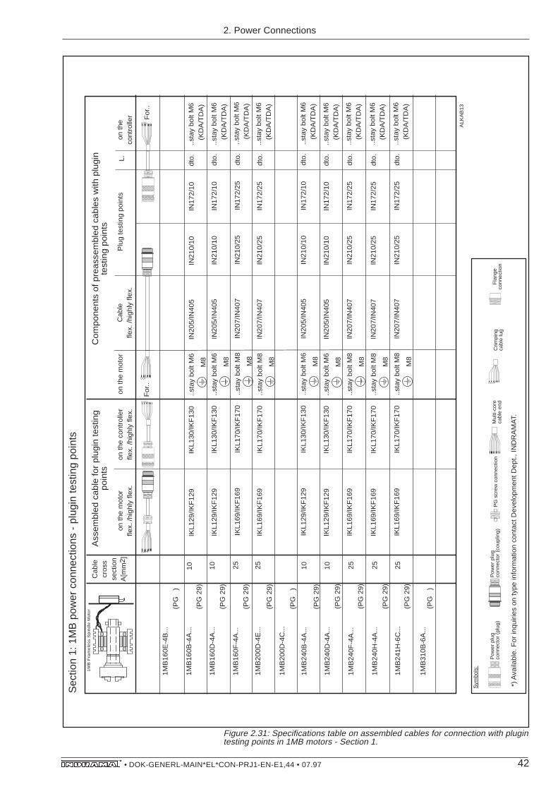
42• DOK-GENERL-MAIN*EL*CON-PRJ1-EN-E1,44 • 07.97
Figure 2.31: Specifications table on assembled cables for connection with plugintesting points in 1MB motors - Section 1.
ALK
AB
13
Pow
er p
lug
conn
ecto
r (p
lug)
Sym
bols
:
Mul
ti-co
re
cabl
e en
dC
rimpi
ngca
ble
lug
Fla
nge
conn
ectio
n
Pow
er p
lug
conn
ecto
r (c
oupl
ing)
PG
scr
ew c
onne
ctio
n
*) A
vaila
ble.
For
inqu
iries
on
type
info
rmat
ion
cont
act D
evel
opm
ent D
ept.,
IND
RA
MA
T.
Cab
lecr
oss
sect
ion
A[m
m2 ]
Ass
embl
ed c
able
for
plug
in te
stin
g po
ints
on th
e m
otor
fle
x. /h
ighl
y fle
x.on
the
cont
rolle
r fle
x. /h
ighl
y fle
x.on
the
mot
orC
able
flex.
/hig
hly
flex.
Plu
g te
stin
g po
ints
L.on
the
cont
rolle
r
Com
pone
nts
of p
reas
sem
bled
cab
les
with
plu
gin
test
ing
poin
ts
1MB
160D
-4A
...10
(PG
29)
1MB
160F
-4A
...25
(PG
29)
1MB
200D
-4E
...25
(PG
29)
1MB
240B
-4A
...10
(PG
29)
1MB
240D
-4A
...10
(PG
29)
1MB
240F
-4A
...25
(PG
29)
1MB
240H
-4A
...25
(PG
29)
1MB
241H
-6C
...25
(PG
29)
1MB
160E
-4B
...
(PG
)
1MB
160B
-4A
...
(PG
29)
1MB
200D
-4C
...
(PG
)
1MB
310B
-6A
...(P
G
)
1M
B F
ram
ele
ss S
pin
dle
Mo
tor
For
..F
or..
IKL1
29/IK
F12
9IN
205/
IN40
5IN
210/
10IN
172/
10..s
tay
bolt
M6
(KD
A/T
DA
)dt
o...s
tay
bolt
M6
M8
IKL1
30/IK
F13
0
IKL1
69/IK
F16
9IN
207/
IN40
7IN
210/
25IN
172/
25..s
tay
bolt
M6
(KD
A/T
DA
)dt
o...s
tay
bolt
M8
M8
IKL1
70/IK
F17
0
IKL1
69/IK
F16
9IN
207/
IN40
7IN
210/
25IN
172/
25..s
tay
bolt
M6
(KD
A/T
DA
)dt
o...s
tay
bolt
M8
M8
IKL1
70/IK
F17
0
IKL1
69/IK
F16
9IN
207/
IN40
7IN
210/
25IN
172/
25..s
tay
bolt
M6
(KD
A/T
DA
)dt
o...s
tay
bolt
M8
M8
IKL1
70/IK
F17
0
IKL1
69/IK
F16
9IN
207/
IN40
7IN
210/
25IN
172/
25..s
tay
bolt
M6
(KD
A/T
DA
)dt
o...s
tay
bolt
M8
M8
IKL1
70/IK
F17
0
IKL1
69/IK
F16
9IN
207/
IN40
7IN
210/
25IN
172/
25..s
tay
bolt
M6
(KD
A/T
DA
)dt
o...s
tay
bolt
M8
M8
IKL1
70/IK
F17
0
IKL1
29/IK
F12
9IN
205/
IN40
5IN
210/
10IN
172/
10..s
tay
bolt
M6
(KD
A/T
DA
)dt
o...s
tay
bolt
M6
M8
IKL1
30/IK
F13
0
IKL1
29/IK
F12
9IN
205/
IN40
5IN
210/
10IN
172/
10..s
tay
bolt
M6
(KD
A/T
DA
)dt
o...s
tay
bolt
M6
M8
IKL1
30/IK
F13
0
10IK
L129
/IKF
129
IN20
5/IN
405
IN21
0/10
IN17
2/10
..sta
y bo
lt M
6(K
DA
/TD
A)
dto.
..sta
y bo
lt M
6
M8
IKL1
30/IK
F13
0
Sec
tion
1: 1
MB
pow
er c
onne
ctio
ns -
plu
gin
test
ing
poin
ts
2. Power Connections

43• DOK-GENERL-MAIN*EL*CON-PRJ1-EN-E1,44 • 07.97
Figure 2.32: Specifications table on assembled cables for connection with plugintesting points in 1MB motors - Section 2.
Sec
tion
2: 1
MB
pow
er c
onne
ctio
ns -
plu
gin
test
ing
poin
ts
2. Power Connections
ALK
AB
14
Pow
er p
lug
conn
ecto
r (p
lug)
Sym
bols
:
Wire
-end
fe
rrul
eC
rimpi
ng
cabl
e lu
gF
lang
e co
nnec
tion
Pow
er p
lug
conn
ecto
r (c
oupl
ing)
PG
scr
ew c
onne
ctio
n
*) A
vaila
ble.
For
inqu
iries
on
type
info
rmat
ion
cont
act D
evel
opm
ent D
ept.,
IND
RA
MA
T.
Cab
lecr
oss
sect
ion
A[m
m2 ]
Ass
embl
ed c
able
for
plug
in te
stin
g po
ints
on th
e m
otor
fle
x. /h
ighl
y fle
x.on
the
cont
rolle
r fle
x. /h
ighl
y fle
x.on
the
mot
orC
able
flex.
/hig
hly
flex.
Plu
g te
stin
g po
int
L.on
the
cont
rolle
r
Com
pone
nts
of a
ass
embl
ed c
able
s w
ith p
lugi
n te
stin
g po
ints
1MB
200D
-4B
...(P
G 2
9)
10
1MB
241H
-6D
...(P
G 2
9)10
1MB
310B
-6B
...25
(PG
29)
1MB
310D
-6B
...25
(PG
29)
1MB
312C
-4A
...35
(PG
29)
1MB
160F
-4B
...
(PG
)
1MB
200D
-4D
...(P
G
)
1MB
200E
-4B
...(P
G
)
1MB
200H
-4B
...(P
G
)
1MB
240F
-4B
...(P
G
)
1MB
310F
-6B
...
(PG
42)
1MB
312B
-4A
...(P
G 2
9)
35
1M
B F
ram
ele
ss S
pin
dle
Mo
tor
For
..F
or..
IN21
7/10
IN17
2/10
IKL1
29/IK
F12
9IN
205/
IN40
5dt
o.IK
L134
/ *)
..sta
y bo
lt M
6
M8
..lin
e-up
term
inal
s
(RA
C2/
RA
C3)
IN21
7/10
IN17
2/10
IKL1
29/IK
F12
9IN
205/
IN40
5dt
o.IK
L134
/ *)
..sta
y bo
lt M
6
M8
..lin
e-up
term
inal
s
(RA
C2/
RA
C3)
IN20
7/IN
407
IN21
0/25
IN17
2/25
dto.
IKL1
69/IK
F16
9*)
..sta
y bo
lt M
8
M8
..lin
e-up
term
inal
s(R
AC
2/R
AC
3)
IN20
7/IN
407
IN21
0/25
IN17
2/25
dto.
..sta
y bo
lt M
8
M8
IKL1
69/IK
F16
9*)
..lin
e-up
term
inal
s(R
AC
2/R
AC
3)
IN26
7no
t ava
ilabl
eno
t ava
ilabl
edt
o...s
tay
bolt
M10
M10
not a
vaila
ble
not a
vaila
ble
..lin
e-up
term
inal
s(R
AC
2/R
AC
3)
dto.
not a
vaila
ble
not a
vaila
ble
..sta
y bo
lt M
10
M10
IN26
7..l
ine-
up te
rmin
als
(RA
C2/
RA
C3)
not a
vaila
ble
not a
vaila
ble
IN20
7/IN
407
IN21
0/25
IN17
2/25
dto.
..sta
y bo
lt M
8
M8
IKL1
69/IK
F16
9*)
..lin
e-up
term
inal
s(R
AC
2/R
AC
3)25
1MB
240H
-4B
...16
(PG
29)
IN20
6/IN
406
IN21
0/16
IN17
2/16
dto.
IKL1
49/IK
F14
9*)
..sta
y bo
lt M
8
M8
..lin
e-up
term
inal
s(R
AC
2/R
AC
3)

44• DOK-GENERL-MAIN*EL*CON-PRJ1-EN-E1,44 • 07.97
Figure 2.33: Table of assembled specifications for connections using plugtesting points in 1MB motors - Section 3.
ALK
AB
15
Pow
er p
lug
conn
ecto
r (p
lug)
Sym
bols
:
Wire
-end
fe
rrul
eC
rimpi
ngca
ble
lug
Fla
nge
conn
ectio
n
Pow
er p
lug
conn
ecto
r (c
oupl
ing)
PG
scr
ew c
onne
ctio
n
*) A
vaila
ble.
For
inqu
iries
on
type
info
rmat
ion
cont
act D
evel
opm
ent D
ept.,
IND
RA
MA
T.
Cab
lecr
oss
sect
ion
A[m
m2 ]
Ass
embl
ed c
able
for
plug
in
test
ing
poin
ts
on th
e m
otor
fle
x. /h
ighl
y fle
x.on
the
cont
rolle
r fle
x. /h
ochf
lex.
on th
e m
otor
Cab
lefle
x. /h
ochf
lex.
Plu
g te
stin
g po
int
L.on
the
cont
rolle
r
Com
pone
nts
of th
e as
sem
bled
cab
le w
ith p
lugi
n te
stin
g po
ints
..lin
e-up
term
inal
s(R
AC
2/R
AC
3)
..Scr
ews
M12
(RA
C4)
1MB
375B
-6B
...
(PG
)
1MB
375D
-6B
...(P
G
)
For
..F
or..
For
..F
or..
Sec
tion
3: 1
MB
pow
er c
onne
ctio
ns -
plu
gin
test
ing
poin
ts
2. Power Connections

45• DOK-GENERL-MAIN*EL*CON-PRJ1-EN-E1,44 • 07.97
Cable Type Cable cross Cable Construction Diameter Bending Radius WeightSection in mm in mm in kg/min mm2 fixed flexible
IN 203 4 4x4,0 + 2x(2x1,5)StC mm2 18,5 ± 1,0 120 270 0,570
IN 204 6 4x6,0 + 2x(2x1,5)StC mm2 18,0 ± 1,0 120 300 0,670
IN 205 10 4x10,0 + 2x(2x1,5)StC mm2 26,0 ± 1,0 200 380 1,100
IN 206 16 4x16,0 + 2x(2x1,5)StC mm2 26,0 ± 1,0 220 390 1,330
IN 207 25 4x25,0 + 2x(2x1,5)StC mm2 28,5 ± 1,0 240 430 1,700
IN 267 35 4x35,0 + 2x(2x1,5)StC mm2 32,0 ± 1,0 150 250 2,170
IN 403 4 4x4,0 + (2x0,75)StC + 15,5 ± 1,0 95 160 0,373 (2x1,0)StC mm2
IN 404 6 4x6,0 + (2x0,75)StC + 18,0 ± 1,0 105 175 0,500 (2x1,0)StC mm2
IN 405 10 4x10,0 + (2x0,75)StC + 21,5 ± 1,0 130 220 0,740 (2x1,0)StC mm2
IN 406 16 4x16,0 + 2x(2x1,0)StC mm2 25,0 ± 1,0 150 250 1,100
IN 407 25 4x25,0 + (2x0,75)StC mm2 26,0 ± 1,0 140 200 0,500
Figure 2.34: Cable specifications for power connections
2. Power Connections
2.1.4. Cable Specifications

46• DOK-GENERL-MAIN*EL*CON-PRJ1-EN-E1,44 • 07.97
2.2. Power connections of theRAC three-phase mains
The power connections between the RAC main spindle controller andthe three-phase mains are arranged in ...
Section 2.2.1: Three-phase mains requirements for direct connectionof RAC controllers to
– grounded three-phase mains, and,
– ungrounded three-phase mains.
Section 2.2.2: Connecting diagrams for
– grounded three-phase mains, and,
– ungrounded three-phase mains.
Section 2.2.3: Tabulated specifications of connecting components,such as,
– required connection cross sections,
– fuses for cable protection,
– power transformers, if needed,
– surge protector type designations, if needed,
– design of connections on the controller.
The power connections of the RAC controller three-phase mains aregenerally internal control cabinet cables which are, for the sake ofexpediency, constructed with single strands. Motor connectioncables from INDRAMAT can, however, also be used.
2. Power Connections
Types

47• DOK-GENERL-MAIN*EL*CON-PRJ1-EN-E1,44 • 07.97
Dependent upon the „AC supply voltage“ option, the following mainsvoltages are permissible for RAC controllers:
Figure 2.35: Permissible mains voltage for RAC controllers.
Voltage at the RAC should not be permitted to periodically exceed1000 V (peak value) between the outer wire (terminal L1, L2, L3) andthe housing!
Non-periodic overvoltages between the outer wire and housing aretolerable for RAC controllers, if these are in accordance with VDE0160 (see Fig. 2.36)!
Type key field no. 5, Voltage permitted „Rated connection voltage“ for.. at X14/L1,L2,L3 ..RAC2.2 ..RAC 4.1 ..RAC 3.1
380 / 3xAC 400V, -15%/+10%, 50..60 Hz
3xAC 400V, -15%/+15%, 50 Hz460 460 / 3xAC 460V, -10%/+10%, 60 Hz
/ 460 3xAC 380 ... 460V/ ±10%, 50..60 Hz
Type key field no. 11, Voltage permitted„Rated connection voltage at X14/L,Nfor control electronics.“Only in RAC 3.1
220 AC 220V, ±10%, 50..60 Hz, 200VA
2.2.1. Three-Phase MainsRequirements
Permissible mains voltage
Non-periodic overvoltage
Periodic voltages
0,1 0,2 0,4 0,6 1 1,3 2 4 6 10 20T (ms)
T
UN+∆U
UN
3
2,6
2,42,32,2
2
1,8
1,6
1,4
1,21,151,11
UN
∆U
∆U 2
Figure 2.36: Non-periodic overvoltages as per VDE 0160.
2. Power Connections

48• DOK-GENERL-MAIN*EL*CON-PRJ1-EN-E1,44 • 07.97
Grounded Three-Phase Mains
The peak value of the rated voltage equals UN = 460V* square root
of 2=650V. Maximum tolerable, non-periodic voltage peak equals1500 V for T<1.3 ms.
RAC controllers can be directly connected to Wye-point and three-phase mains grounded on the outer wire. Should the mains voltagenot agree with the RAC rated connection voltage, then anautotransformer is needed to equalize the voltage (see Figure 2.37)!
Ungrounded Three-Phase Mains Ungrounded three-phase mains run increased danger of unsafeovervoltages occurring between the outer wire and the housing. RACcontrollers can only be operated on these mains
– if the drive is connected via an isolating transformer, or,
– if surge arresters safeguard the facility.
The RAC controller is most protected against damage from overvoltagewhen it is connected via an isolating transformer. The drive operateswith the greatest possible safety. The use of an isolating transformeris recommended in that case where an ungrounded three-phasemains also requires voltage to be matched to the permissible connec-tion voltage of the unit (see Figure 2.38).
RAC controllers may only then be operated with ungrounded three-phase mains if the facility is secured with a surge arrester. Anautotransformer can be used in the event that voltage must bematched to the permissible rated connection voltage of the unit.
The recommended surge arrester safeguards upto a leakage currentof l2t=750A2s. For thermal reasons, greater leakage currents evokea response from the signal contact of the surge arrester.
The signal contact expediently triggers the separation of the machinefrom the mains (see Figure 2.39). Should this not be possible, thenthe signal contact is switched into the control system of the mainscontactor of the RAC (see Figure 2.40).
The operational safety of the drives is greater if an isolating trans-former is used, than if a surge arrester is used. The initial expensewith larger loads is, however, significantly smaller. The surge arrest-ers are destroyed after one use and must be exchanged!
2. Power Connections
Connection via anIsolating Transformer
Surge Arresters as Safeguards
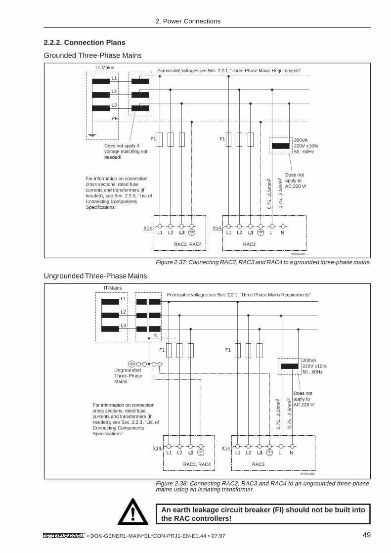
49• DOK-GENERL-MAIN*EL*CON-PRJ1-EN-E1,44 • 07.97
Figure 2.37: Connecting RAC2, RAC3 and RAC4 to a grounded three-phase mains.
L1 L2 L3L3
RAC2, RAC4
Permissible voltages see Sec. 2.2.1, "Three-Phase Mains Requirements"
For information on connection cross sections, rated fuse currents and transformers (if needed), see Sec. 2.2.3, "List of Connecting Components Specifications".
X14
L1
L2
L3
PE
L1 L2 L3L3
RAC3
X14
APRAC001
Does not apply if voltage matching not needed!
TT-Mains
L N
Does not apply to AC 220 V!
0,75
...2,
5mm
2
0,75
...2,
5mm
2
F1 F1 200VA220V ±10%50...60Hz
An earth leakage circuit breaker (FI) should not be built intothe RAC controllers!
Figure 2.38: Connecting RAC2, RAC3 and RAC4 to an ungrounded three-phasemains using an isolating transformer.
Ungrounded Three-Phase Mains
L1 L2 L3L3
RAC2, RAC4
X14
L1
L2
L3
L1 L2 L3L3
RAC3
X14
APRAC002
IT-Mains
L N
Does not apply to AC 220 V!
0,75
...2,
5mm
2
0,75
...2,
5mm
2
F1F1
Ungrounded Three-Phase Mains
N
Permissible voltages see Sec. 2.2.1, "Three-Phase Mains Requirements"
For information on connection cross sections, rated fuse currents and transformers (if needed), see Sec. 2.2.3, "List of Connecting Components Specifications".
200VA220V ±10%50...60Hz
2. Power Connections
2.2.2. Connection Plans
Grounded Three-Phase Mains

50• DOK-GENERL-MAIN*EL*CON-PRJ1-EN-E1,44 • 07.97
L1 L2 L3L3
RAC2, RAC4
For information on connection cross sections, rated fuse currents and transformers (if needed), see Sec. 2.2.3, "List of Connecting Components Specifications".
X14
L1
L2
L3
L1 L2 L3L3
RAC3
APRAC003
IT-Mains
L N
Does not apply to AC 220 V!
0,75
...2,
5mm
2
0,75
...2,
5mm
2
Remote control
F2
X14
F1F1
F3
F2
Control cabinet - earth potential.
Machine master switch
Does not apply if voltage matching not
needed! Permissible voltage see Sec. 2.2.1, "Three-Phase Mains Requirements"
200VA220V ±10%50...60Hz
Figure 2.39: Connecting RAC2, RAC3 and RAC4 to ungrounded three-phasemains, actuation of surge arrester triggers mains separation.
2. Power Connections

51• DOK-GENERL-MAIN*EL*CON-PRJ1-EN-E1,44 • 07.97
L1 L2 L3
RAC2, RAC4
For information on connection cross sections, rated fuse currents and transformers (if needed), see Sec. 2.2.3, "List of Connecting Components Specifications".
X14
L1
L2
L3
L1 L2 L3
RAC3
APRAC004
IT-Mains
L N
Does not apply toAC 220 V!
0,75
...2,
5mm
2
0,75
...2,
5mm
2
X14
F1F1
F3
F2
Control cabinet -earth potential
Does not apply if voltage matching not
needed!
43X15
OF
F
Control
43X15
OF
F
Permissible voltage, see Sec. 2.2.1, "Three-Phase Mains Requirements".
Relay Relay Relay Relay
Control
Response from F2triggers break.
F2
200VA220V ±10%50...60Hz
For thermal reasons, the surge arresters disconnect at l2t=750A2s(30s at 5A) once they are actuated (leakage current). They are thenno longer functional and must be exchanged!
Figure 2.40: Connecting RAC2, RAC3 and RAC4 to ungrounded three-phasemains, actuation of surge arrester triggers release of mains contactor in theRAC.
An earth leakage circuit breaker (Fl) must not be built into theRAC controller!
2. Power Connections

52• DOK-GENERL-MAIN*EL*CON-PRJ1-EN-E1,44 • 07.97
Main spindle PRated
IMains RAC
Fuse Cable cross motor in kW in A F1, Type section in mm2
2AD132B-...-DS 10 191MB200E-4B-... 11 21 3xNH25gl 41MB240F-4B-... 11 26
2AD132C-..-CS 15 291MB240H-4B-... 15 291MB241H-6D-... 16 30 3xNH35gl 61MB200D-4D-... 19 361MB310B-6B-... 19 36
1MB200H-4B-... 19,5 371MB312B-4A-... 20 382AD132D-...-AS 22 42 3xNH50gl 101MB310D-6B-... 25 481MB312C-4A-... 25 48
2AD160B-...-BS 30 57 3xNH63gl 161MB310F-6B-... 35 66
2AD160C-...-BS 37 70 3xNM80gl 251MB375B-6B-... 40 76
2AD180C-...-BS 52 99 3xNH100gl 351MB375B-6B-... 55 105
2AD180D-...-BS 63 120 3xNH125gl 50
2AD200C-...-AS 79 150 3xNH160gl 2x25
2AD225C-...-AS 93 176 3xNH200gl 2x35
2.2.3. Connecting Compo-nents Data List
The dimensions of the mains fuse and the mains connection cableare dependent upon the rated output of the main spindle motoroperated on the RAC controller.
If the rated output of the main spindle motor is fully utilized during aprocessing cycle, then the following values are achieved:
Figure 2.41: Mains connection specifications with rated service of main spindlemotors, or frameless spindle motors (valid for 3 x AC 380 V ... 3 X AC 460 V).
Appropriate circuit breakers can be used instead of NH-fuses!
2. Power Connections
Connection cross section,type of fuse
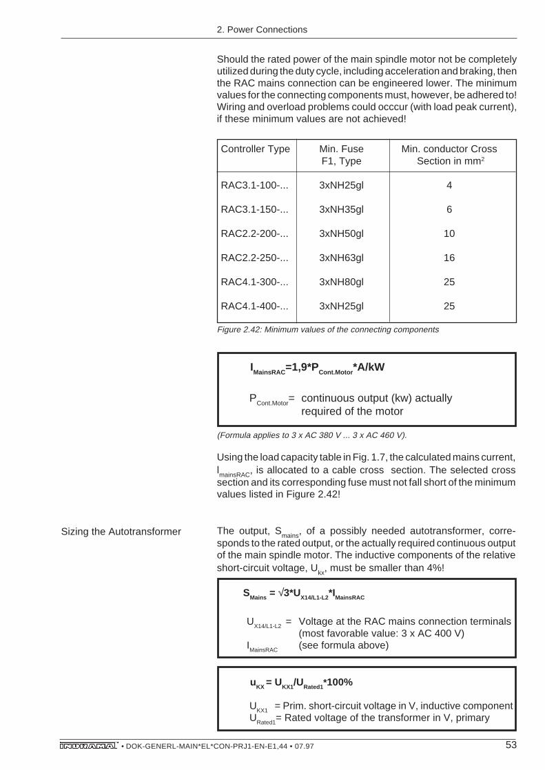
53• DOK-GENERL-MAIN*EL*CON-PRJ1-EN-E1,44 • 07.97
Should the rated power of the main spindle motor not be completelyutilized during the duty cycle, including acceleration and braking, thenthe RAC mains connection can be engineered lower. The minimumvalues for the connecting components must, however, be adhered to!Wiring and overload problems could occcur (with load peak current),if these minimum values are not achieved!
Controller Type Min. Fuse Min. conductor CrossF1, Type Section in mm2
RAC3.1-100-... 3xNH25gl 4
RAC3.1-150-... 3xNH35gl 6
RAC2.2-200-... 3xNH50gl 10
RAC2.2-250-... 3xNH63gl 16
RAC4.1-300-... 3xNH80gl 25
RAC4.1-400-... 3xNH25gl 25
Figure 2.42: Minimum values of the connecting components
(Formula applies to 3 x AC 380 V ... 3 x AC 460 V).
Using the load capacity table in Fig. 1.7, the calculated mains current,lmainsRAC, is allocated to a cable cross section. The selected crosssection and its corresponding fuse must not fall short of the minimumvalues listed in Figure 2.42!
The output, Smains, of a possibly needed autotransformer, corre-sponds to the rated output, or the actually required continuous outputof the main spindle motor. The inductive components of the relativeshort-circuit voltage, Ukx, must be smaller than 4%!
SMains = √3*UX14/L1-L2*IMainsRAC
UX14/L1-L2
= Voltage at the RAC mains connection terminals(most favorable value: 3 x AC 400 V)
IMainsRAC (see formula above)
UKX1 = Prim. short-circuit voltage in V, inductive componentURated1= Rated voltage of the transformer in V, primary
IMainsRAC =1,9*PCont.Motor *A/kW
PCont.Motor= continuous output (kw) actuallyrequired of the motor
uKX = UKX1/URated1*100%
2. Power Connections
Sizing the Autotransformer

54• DOK-GENERL-MAIN*EL*CON-PRJ1-EN-E1,44 • 07.97
Controller Type Minimum Output SMains (kVA)
RAC3.1-100-... 25
RAC3.1-150-... 40
RAC2.2-200-... 50
RAC2.2-250-... 65
RAC4.1-300-... 80
RAC4.1-400-... 100
Sizing the Isolating Transformer
Figure 2.43: Minimum transformer output if the RAC controller is connected via ian isolating transformer.
The already stated formulae are used to calculate the mains current,ImainsRAC
, and the mains connection output, Smains
, of the main spindlemotor:
(Formula valid for 3 x AC 380 V ... 3 x AC 460 V.)
Pcont.Motor= continuous output (kw) actuallydemanded of motor
ImainsRAC =1,9*Pcont.Motor *A/kW
Smains = √3*UX14/L1-L2*ImainsRAC
UX14/L1-L2 = Voltage at mains connection terminals of RAC (most favorable value: 3 x AC 400 V)
ImainsRAC
(see above formula)
2. Power Connections
The output, Smains, of an isolating transformer, if needed, also de-pends upon the rated output, or the actual continuous output requiredof the main spindle motor.
The stray inductance of an isolating transformer is significantly higherthan that of an autotransformer. Depending upon the type of RAC, theminimum transformer output of the isolating transformer must, as aresult, achieve the minimum value! The inductive component of therelative short-circuit voltage, U
kx, must be smaller than 4%!
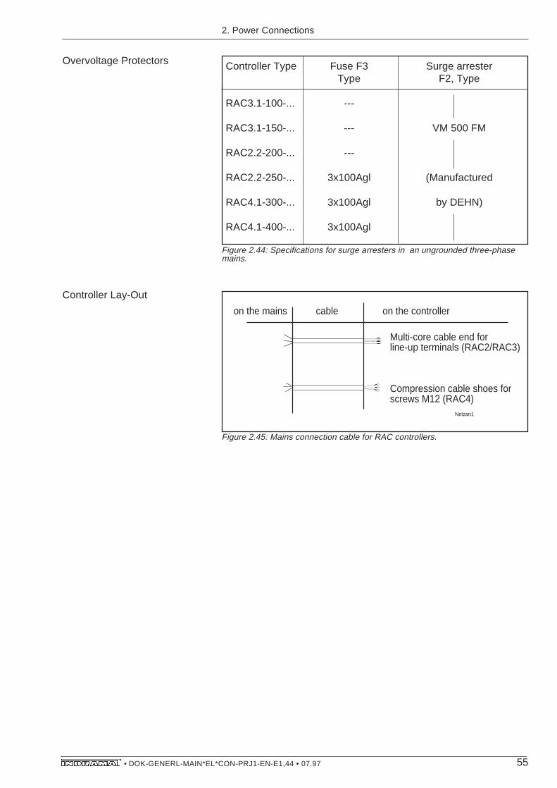
55• DOK-GENERL-MAIN*EL*CON-PRJ1-EN-E1,44 • 07.97
Controller Type Fuse F3 Surge arresterType F2, Type
RAC3.1-100-... ---
RAC3.1-150-... --- VM 500 FM
RAC2.2-200-... ---
RAC2.2-250-... 3x100Agl (Manufactured
RAC4.1-300-... 3x100Agl by DEHN)
RAC4.1-400-... 3x100Agl
Overvoltage Protectors
Figure 2.44: Specifications for surge arresters in an ungrounded three-phasemains.
on the mains cable on the controller
Multi-core cable end forline-up terminals (RAC2/RAC3)
Compression cable shoes forscrews M12 (RAC4)
Netzan1
Figure 2.45: Mains connection cable for RAC controllers.
2. Power Connections
Controller Lay-Out

56• DOK-GENERL-MAIN*EL*CON-PRJ1-EN-E1,44 • 07.97
3. Feedback andCNC Connections
Signal exchange with the CNC control takes place via the CNCconnections; feedback of position or speed of the motor shaft and thespindle to the main spindle controller via the feedback connections.
The Section on feedback and CNC connections is broken down into
Section 3.1: Division of the types of connections
– direct connection
– connection with link terminal
– connection with plug design
– connection with plugin testing points
Section 3.2: Connection diagrams for the direct connection of
– CNC control and controller
– feedback and controller for all standard interfaces and optionalinterfaces
Section 3.3: Specifications table of the assembled cables for
– direct connection and connections using link terminals
– connection with plug design
– connection with plugin testing points
Section 3.4: Specifications table for cables, such as,
– type designation
– conductor cross sections and cable construction
– cable diameter
– inflection radii, and,
– length-related weight
3. Feedback and CNC Connections

57• DOK-GENERL-MAIN*EL*CON-PRJ1-EN-E1,44 • 07.97
3.1. Types of feedback andCNC connections
There are four types of assembled feedback and CNC connections.
Figure 3.1: Four types of assembled feedback and CNC connections
This type of connection is characterized by the lowest number ofimperfections in comparison to other connection types.
Figure 3.2: Assembled cables for direct connections (also see figure 3.22).
3. Feedback and CNC Connections
direct with intermediate terminal with plug with plugin on terminal strip design testing points
Types of Feedback and CNCConnection
Direct connection
Plug connector(plug)for feedback connection,elbow type
Symbols:
Multi-corecable end
Wall breakthrough
on the controller Cable feedback side
CNC side
XXkab01
D-sub-plug connector
Plug connector(plug)for feedback connection, straight type

58• DOK-GENERL-MAIN*EL*CON-PRJ1-EN-E1,44 • 07.97
This type of connection permits an easy diagnosis of the signalexchange to the CNC control at the intermediate terminal points.
Intermediate terminals in feedback connections with incrementalencoder are not to be recommended because of increased sensitivityto interference! Intermediate terminals are not permitted with high-resolution motor and spindle feedback!
Figure 3.3: Assembled cables for intermediate terminals on the terminal strip(also see Figure 3.22).
The control cabinet can be finished entirely independent of themachine with this type of connection. The melding of machine andcontrol cabinet is quick and simple.
In addition, damaged cables on the outside of the control cabinet canbe quickly and safely exchanged.
Figure 3.4: Assembled cables for plug design (also see Figure 3.23).
Connection withIntermediate Terminals
Connection with plug design
on the controller cable Plug design cable feedback side
XXkab03
CNC side
Plug connector (plug)for feedback connection,elbow type
Symbols:
Multi-corecable ends
Wall breakthrough
D-sub-plug connector
Plug connector (plug)for feedback connection,straight type
on the controller cable terminal strip cable feedback side
XXkab02
CNC side
Plug connector (plug) for feedback connection, elbow type
Symbols:
Multi-corecable ends
Wall breakthrough
D-sub-plug connector
Plug connector (plug) for feedback connection, straight type
3. Feedback and CNC Connections
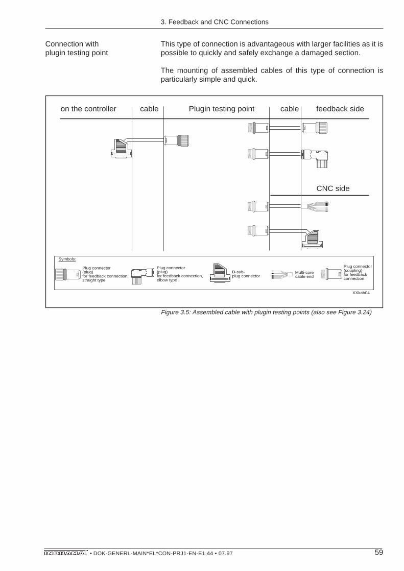
59• DOK-GENERL-MAIN*EL*CON-PRJ1-EN-E1,44 • 07.97
Connection withplugin testing point
This type of connection is advantageous with larger facilities as it ispossible to quickly and safely exchange a damaged section.
The mounting of assembled cables of this type of connection isparticularly simple and quick.
Figure 3.5: Assembled cable with plugin testing points (also see Figure 3.24)
on the controller cable Plugin testing point cable feedback side
XXkab04
CNC side
Plug connector (coupling)for feedbackconnection
Plug connector (plug)for feedback connection,elbow type
Symbols:
Multi-corecable end
D-sub-plug connector
Plug connector (plug)for feedback connection,straight type
3. Feedback and CNC Connections

60• DOK-GENERL-MAIN*EL*CON-PRJ1-EN-E1,44 • 07.97
3.2. Connecting plans fordirect connections
Standard interfacesand optional interfaces
3. Feedback and CNC Connections
Only the connection plans for the direct connection of feedback andCNC connections are depicted. They do, however, apply to all othertypes of connections. The respective testing points do not alter theallocation of the connections for feedback or CNC control and mainspindle controller.
The connection plans are to be used to develop the plant connectiondiagrams. The plant connection diagrams of the machine manufac-turer are to be used when wiring the plant!
Main spindle controllers are always equipped with motor feedbackconnection (X3, standard) and control input, signal and analogueoutputs (X2, standard). The controllers can optionally be equippedwith additional feedback and CNC interfaces.
The optional interfaces are listed in the type designations of thecontroller to be mounted. The type key is listed in the documentationabout main spindle controllers - „Project Planning Notes“.
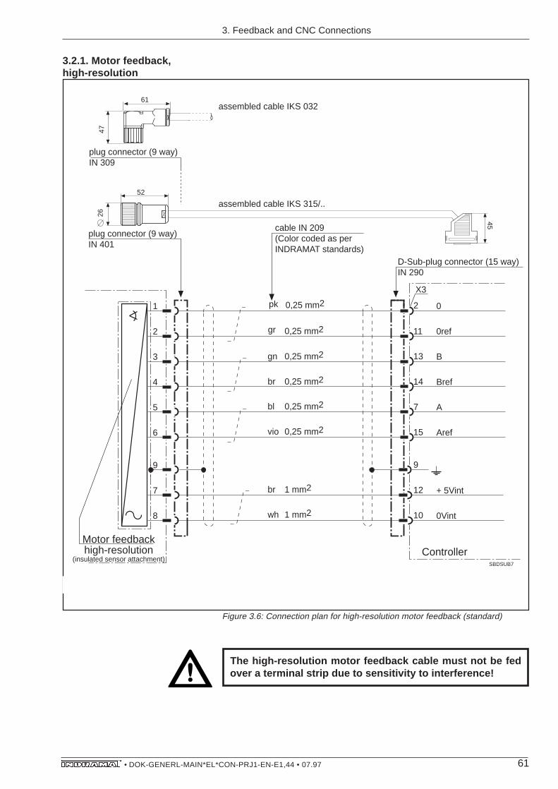
61• DOK-GENERL-MAIN*EL*CON-PRJ1-EN-E1,44 • 07.97
3.2.1. Motor feedback,high-resolution
Figure 3.6: Connection plan for high-resolution motor feedback (standard)
0
SBDSUB7
X3
cable IN 209(Color coded as per INDRAMAT standards)
D-Sub-plug connector (15 way)IN 290
Controller
2
11
13
14
15
pk
gr
br
gn
0,25 mm2
0,25 mm2
0,25 mm2
0,25 mm2
0ref
B
Bref
Aref
A7
9
12
10
+ 5Vint
0Vint
1
2
3
4
5
6
9
7
8
Motor feedbackhigh-resolution
(insulated sensor attachment)
vio
bl
0,25 mm2
0,25 mm2
wh
br
1 mm2
1 mm2
plug connector (9 way)IN 401
assembled cable IKS 032
assembled cable IKS 315/..52
2661
47
45
plug connector (9 way)IN 309
IKS 315
The high-resolution motor feedback cable must not be fedover a terminal strip due to sensitivity to interference!
3. Feedback and CNC Connections
IKS315
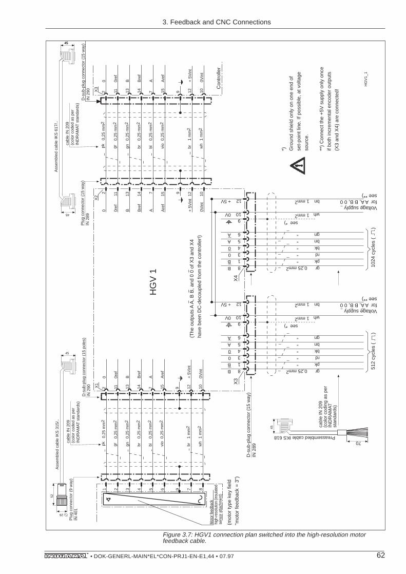
62• DOK-GENERL-MAIN*EL*CON-PRJ1-EN-E1,44 • 07.97
0
X1
cabl
e IN
209
(col
or c
oded
as
per
IND
RA
MA
T s
tand
ards
)D
-sub
-plu
g co
nnec
tor
(15
pole
s)IN
290 2 11 13 14 15
pk gr brgn
0,25
mm
2
0,25
mm
2
0,25
mm
2
0,25
mm
2
0ref
B Bre
f
Are
f
A7 9 12 10
+ 5
Vin
t
0Vin
t
1 2 3 4 5 6 9 7 8
Mot
or fe
edba
ck
high
-reso
lutio
n (in
sula
ted
sens
or a
ttach
men
t)
vio
bl
0,25
mm
2
0,25
mm
2
wh
br
1 m
m2
1 m
m2
Plu
g co
nnec
tor
(9 w
ay)
IN 4
01
Ass
embl
ed c
able
IKS
315
/..52
26
45
grpkrdbkbngn
wh
bn
""""
0,25 mm2BB00AA
cabl
e IN
209
(col
or c
odin
g as
per
IND
RA
MA
T
stan
dard
s)
813456
910
12
0V
+ 5V
"
1 mm2
70Preassembled cable IKS 618
1 mm2
D-s
ub-p
lug
conn
ecto
r (1
5 w
ay)
IN 2
89
X3
0
X3
cabl
e IN
209
(col
or c
oded
as
per
IND
RA
MA
T s
tand
ards
)D
-sub
-plu
g co
nnec
tor
(15
way
)IN
290
Con
trol
ler
2 11 13 14 15
pk gr brgn
0,25
mm
2
0,25
mm
2
0,25
mm
2
0,25
mm
2
0ref
B Bre
f
Are
f
A7 9 12 10
+ 5
Vin
t
0Vin
t
vio
bl
0,25
mm
2
0,25
mm
2
wh
br
1 m
m2
1 m
m2
Plu
g co
nnec
tor
(15
way
)IN
289
Ass
embl
ed c
able
IKS
617
/..
45
grpkrdbkbngn
wh
bn
""""
0,25 mm2BB00AA
813456
910
12
0V
+ 5V
"
1 mm2
1 mm2
X4
2 11 13 14 157 9 12 10
0 0ref
B Bre
f
Are
f
A + 5
Vin
t
0Vin
t
X2
(mot
or ty
pe k
ey fi
eld
"mot
or fe
edba
ck =
3")
(The
out
puts
A A
, B B
, and
0 0
of X
3 an
d X
4
have
bee
n D
C-d
ecou
pled
from
the
cont
rolle
r!)
HG
V 1
45
45
512
cycl
es (
)10
24 c
ycle
s (
)
Voltage supply for A A, B B, 0 0see **)
Voltage supply for A A, B B, 0 0see **)
45
HG
V1_
1
see *)
*) Gro
und
shie
ld o
nly
on o
ne e
nd o
f
set-
poin
t lin
e. If
pos
sibl
e, a
t vol
tage
sour
ce.
**)
Con
nect
the
+5V
sup
ply
only
onc
e
if bo
th in
crem
enta
l enc
oder
out
puts
(X3
and
X4)
are
con
nect
ed!
see *)
Figure 3.7: HGV1 connection plan switched into the high-resolution motorfeedback cable.
3. Feedback and CNC Connections
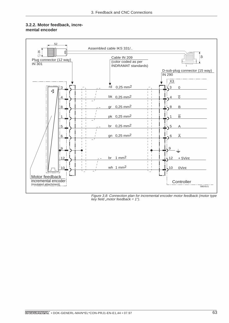
63• DOK-GENERL-MAIN*EL*CON-PRJ1-EN-E1,44 • 07.97
0
SBDSU1
X3
Cable IN 209(color coded as perINDRAMAT standards)
D-sub-plug connector (15 way)IN 290
Controller
3
4
8
1
6
rd
bk
pk
gr
0,25 mm2
0,25 mm2
0,25 mm2
0,25 mm2
0
B
B
A
A5
9
12
10
+ 5Vint
0Vint
3
4
8
1
5
6
9
12
10
Motor feedback incremental encoder(insulated attachment)
gn
br
0,25 mm2
0,25 mm2
wh
br
1 mm2
1 mm2
Plug connector (12 way)IN 301
Assembled cable IKS 331/..52
26
45
1
IKS 331
3. Feedback and CNC Connections
3.2.2. Motor feedback, incre-mental encoder
Figure 3.8: Connection plan for incremental encoder motor feedback (motor typekey field „motor feedback = 1“).
IKS 317

64• DOK-GENERL-MAIN*EL*CON-PRJ1-EN-E1,44 • 07.97
3.2.3. Spindle Feedback,high-resolution
IKS 314
0
SBDSU3
X5
Cable IN 209(color coded as perINDRAMAT standards)
D-sub plug connector (15 way)IN 289
Controller
3
4
8
1
6
rd
bk
pk
gr
0,25 mm2
0,25 mm2
0,25 mm2
0,25 mm2
0
B
B
A
A5
9
12
10
+ 5Vint
0Vint
3
4
8
1
5
6
9
12
10
Spindle feedback incremental encoder(insulated sensor attachment)
gn
br
0,25 mm2
0,25 mm2
wh
br
1 mm2
1 mm2
Plug connector (12 way)IN 301
Assembled cable IKS 327/..52
26
61
47
45
Plug connector (12 way)IN 351
1
The cable to the high-resolution spindle feedback must notbe fed over a terminal strip because of sensitivity tointerference!
3. Feedback and CNC Connections
Figure 3.9: Connection plan for high-resolution main spindle position encoder asspindle feedback (controller with „additional encoder input = P“ option).
IKS314
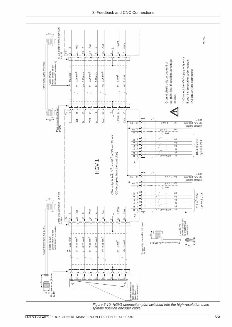
65• DOK-GENERL-MAIN*EL*CON-PRJ1-EN-E1,44 • 07.97
Figure 3.10: HGV1 connection plan switched into the high-resolution mainspindle position encoder cable.
0
X2
Cab
le IN
209
(col
or c
oded
as
per
IND
RA
MA
T s
tand
ards
)D
-sub
-plu
g co
nnec
tor
(15
way
)IN
289 2 11 13 14 15
0,25
mm
2
0,25
mm
2
0,25
mm
2
0,25
mm
2
0 ref
B Bre
f
Are
f
A7 9 12 10
+ 5
Vin
t
0Vin
t
1 2 3 4 5 6 9 7 8
Spi
ndle
feed
back
hi
gh-r
esol
utio
n (in
sula
ted
sens
or a
ttach
men
t)
0,25
mm
2
0,25
mm
2
1 m
m2
1 m
m2
Plu
g co
nnec
tor
(9 w
ay)
IN 4
01
Ass
embl
ed c
able
IKS
314
/..52
26
45
1
pk gr brgn vio
bl wh
br
0
X2
Cab
le IN
209
(col
or c
oded
as
per
IND
RA
MA
T s
tand
ards
)D
-sub
-plu
g co
nnec
tor
(15
way
)IN
289 2 11 13 14 15
0,25
mm
2
0,25
mm
2
0,25
mm
2
0,25
mm
2
0 ref
B Bre
f
Are
f
A7 9 12 10
+ 5
Vin
t
0Vin
t
0,25
mm
2
0,25
mm
2
1 m
m2
1 m
m2
Plu
g co
nnec
tor
(15
way
)IN
290
Ass
embl
ed c
able
IKS
049
/..
45
1
pk gr brgn vio
bl wh
br
45
1
X1 2 11 13 14 157 9 12 10
0 0 ref
B Bre
f
Are
f
A + 5
Vin
t
0Vin
t
D-s
ub-p
lug
conn
ecto
r (1
5 w
ay)
IN 2
89
grpkrdbkbngn
wh
bn
""""
0,25 mm2BB00AA
Line
IN 2
09(c
olor
cod
ed a
cc.
to IN
DR
AM
AT
st
anda
rds)
813456
910
12
0V
+ 5V
"
1 mm2
70Preassembled cable IKS 618
1 mm2
grpkrdbkbngn
wh
bn
""""
0,25 mm2BB00AA
813456
910
12
0V
+ 5V
"
1 mm2
1 mm2
X3
X4
(The
out
puts
A A
, B B
, and
0 0
of X
3 an
d X
4 ar
e
CD
-dec
oupl
ed fr
om th
e co
ntro
ller)
512
or 1
024
cycl
es (
)
1024
or
2048
cycl
es (
)
Voltage supply for A A, B B, 0 0see **)
Voltage supply for A A, B B, 0 0see **)
HG
V 1
HG
V1_
2
45
1
Gro
und
shie
ld o
nly
on o
ne e
nd o
f
set-
poin
t lin
e. If
pos
sibl
e, a
t vol
tage
sour
ce.
**)
Con
nect
the
+5V
sup
ply
only
onc
e
if bo
th in
crem
enta
l enc
oder
out
puts
(X3
and
X4)
are
con
nect
ed!
see *)
see *)
3. Feedback and CNC Connections
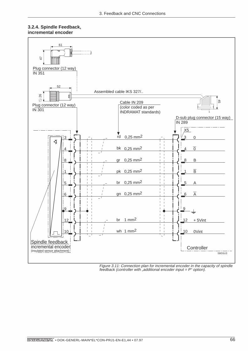
66• DOK-GENERL-MAIN*EL*CON-PRJ1-EN-E1,44 • 07.97
0
SBDSU3
X5
Cable IN 209(color coded as perINDRAMAT standards)
D-sub plug connector (15 way)IN 289
Controller
3
4
8
1
6
rd
bk
pk
gr
0,25 mm2
0,25 mm2
0,25 mm2
0,25 mm2
0
B
B
A
A5
9
12
10
+ 5Vint
0Vint
3
4
8
1
5
6
9
12
10
Spindle feedback incremental encoder(insulated sensor attachment)
gn
br
0,25 mm2
0,25 mm2
wh
br
1 mm2
1 mm2
Plug connector (12 way)IN 301
Assembled cable IKS 327/..52
26
6147
45
Plug connector (12 way)IN 351
1
IKS 327
3.2.4. Spindle Feedback,incremental encoder
3. Feedback and CNC Connections
Figure 3.11: Connection plan for incremental encoder in the capacity of spindlefeedback (controller with „additional encoder input = P“ option).
IKS327
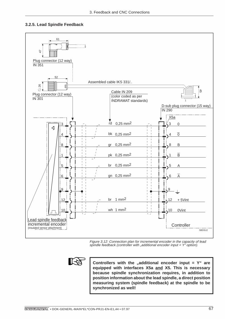
67• DOK-GENERL-MAIN*EL*CON-PRJ1-EN-E1,44 • 07.97
3.2.5. Lead Spindle Feedback
0
SBDSU2
X5a
Cable IN 209(color coded as perINDRAMAT standards)
D-sub plug connector (15 way)IN 290
Controller
3
4
8
1
6
rd
bk
pk
gr
0,25 mm2
0,25 mm2
0,25 mm2
0,25 mm2
0
B
B
A
A5
9
12
10
+ 5Vint
0Vint
3
4
8
1
5
6
9
12
10
Lead spindle feedbackincremental encoder(insulated sensor attachment)
gn
br
0,25 mm2
0,25 mm2
wh
br
1 mm2
1 mm2
Plug connector (12 way)IN 301
Assembled cable IKS 331/..52
2661
47
45
Plug connector (12 way)IN 351
1
Figure 3.12: Connection plan for incremental encoder in the capacity of leadspindle feedback (controller with „additional encoder input = Y“ option).
Controllers with the „additional encoder input = Y“ areequipped with interfaces X5a and X5. This is necessarybecause spindle synchronization requires, in addition toposition information about the lead spindle, a direct positionmeasuring system (spindle feedback) at the spindle to besynchronized as well!
IKS 331
3. Feedback and CNC Connections

68• DOK-GENERL-MAIN*EL*CON-PRJ1-EN-E1,44 • 07.97
3.2.6. Control input, signaland analogue outputs,Bb-contact
grwhbnye/blckyelgn/bkrdblrdbkviogr/pkbl/rdwh/gn
(see below!)
wh/yegnye/bnwh/grgr/bnwh/pkpk/bnwh/blbn/blwh/pkbn/rdwh/bkbn/bkgr/gnyel/grgn/rdpk/gnye/pkgn/blyel/bl
0,5 mm20,25 mm2
"""""""""""""
"""""""""""""""""
0,25 mm2
0,5 mm2
0,25 mm20V ext0V intAS (KDA/TDA only)READYN = CMDN < MININ POS90% LOADTEMPWARNLIMITSPEED CHANGE 1SPEED CHANGE 2LOAD LIMITRF SLAVESPINDLE CONT
24V int24V extAnalogue output MAnalogue output N0V int
RFRUNPOS 1POS 2MD-REDOSCILLATEPAR 1PAR 2LIMIT 1LIMIT 2LIMIT 4SPEED 1SPEED 2EXT POS
SBDSUB1
BbBb
X11 KDA/TDAX15 RAC
Bb-contact24V, 1A
X2
2 way plug terminalin KDA/TDA,found in E••-•DA10 way plug terminalin RAC (also see Fig. 3.18),found in E1-RAC
Cable IN 271(color coded as perINDRAMAT standards)
D-sub-plug connector (37 way)IN 293
45200
Assembled cable IKS 610/..
123456789101112131415
18
17
19202122232425262728293031323334353637
1
E-STOP (RAC only)
Voltage level input
+36 V
+24 V
+18 V
0 V
+5 V
0 (low) 1 (high)
Voltage level output
+36 V
+24 V
+18 V
0 V
+5 V
0 (low) 1 (high)
Voltage level for 24 Vext
+36 V
+18 V
Voltage supplyfrom the control
U
t
IKS 610
3. Feedback and CNC Connections
Figure 3.13: Connection plan for control input, signal and analogue outputs, Bb-contact (standard).
IKS610

69• DOK-GENERL-MAIN*EL*CON-PRJ1-EN-E1,44 • 07.97
E1
SBDSUB6
X4
Cable IN 233(color coded asper INDRAMAT standards)
D-sub-plug connector (9 way)IN 287
Controller
1
2
5
6
4
9
8
7
bn
wh
yel
gn
0,22 mm2
0,22 mm2
0,22 mm2
0,22 mm2 *)
*)
*) Internal shielding can be dropped if INDRAMAT cables are not used!
E2
E3
E4
+15VM
- 15VM
45
70Assembled cable IKS 045/..
1
(see below!)
+15 V
-15 V
Voltage levelanalogue inputs
The control and signal outputs are DC-decoupled from the controller.The control must supply the outputs with *24V/0 V. Should this notbe possible, then connect terminal 1 with 2 and 18 with 19!
Ground the shield only on one end of the cable. If possible,at voltage source.
3.2.7. Speed set-point,analogue +/- 10V
Figure 3.14: Connection plan for analogue speed set-point(„speed set-point=A“ option)
Inputs E1/E2 and E3/E4 for the analogue set-point are designed asdifferential inputs.
IKS 045
Ground the shield only on one end of the set-point cable. Ifpossible, at voltage source!
Do not directly connect a contactor coil via the relay contactBb, as the high intermittent currents caused by frequentswitching could overload the relay contact and cause it tofail.
3. Feedback and CNC Connections
IKS045

70• DOK-GENERL-MAIN*EL*CON-PRJ1-EN-E1,44 • 07.97
whbngnyelgrpk
blrdbkviowh/bnwh/gnwh/yelwh/gr
wh/rdwh/bk
bn/gnbn/yel
"""""""""""""
""
0,25 mm2 Bit 1
-15 V int (max. 150 mA)+15 V int (max. 150 mA)
0V ext0V ext
SBDSUB3
X4
Cable 20x0,25(color coded as perINDRAMAT standards)
D-sub-plug connector (25 way)IN 291
"
wh/pkwh/bl "
""
Controller
Bit 2Bit 3Bit 4Bit 5Bit 6Bit 7Bit 8Bit 9Bit 10Bit 11Bit 12Bit 13Bit 14Bit 15DATA VALID
45
200Assembled cable IKS 612
12345678910111213141516
1819
2122
25
1
Voltage level
+36 V
+24 V
+18 V
0 V
+5 V
0 (low) 1 (high)
(see below!)
3.2.8. Speed set-point, digital,16 bit parallel
Ground shield only at one end of the cable. If possible, atvoltage source!
Figure 3.15: Connection plan for digital speed set-points(„speed set-point=D“ option)
IKS 612
3. Feedback and CNC Connections
The inputs for the digital speed set-point (bit 1 ... bit 15, DATA VALID)are DC-decoupled from the controller. Terminal 21 should be con-nected to the OV potential of the control! The inputs are then set withthe +24V potential of the control! If the control does not supply *24V/0, then connect terminal 18 with 21 and set the inputs via terminal 19!Current consumption approx. 15mA per input!
IKS612
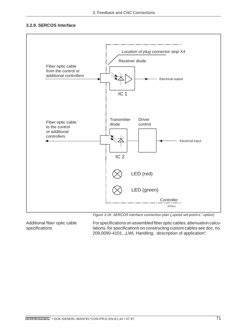
71• DOK-GENERL-MAIN*EL*CON-PRJ1-EN-E1,44 • 07.97
3.2.9. SERCOS Interface
APSerc
Controller
Electrical output
Location of plug connector strip X4
Receiver diodeFiber optic cable from the control or additional controllers
Electrical input
Driver controlFiber optic cable
to the control or additional controllers
IC 1
IC 2
LED (red)
LED (green)
Transmitter diode
Figure 3.16: SERCOS interface connection plan („speed set-point=L“ option)
For specifications on assembled fiber optic cables, attenuation calcu-lations, for specifications on constructing custom cables see doc. no.209.0090-4101, „LWL Handling; description of application“.
Additional fiber optic cablespecifications
3. Feedback and CNC Connections

72• DOK-GENERL-MAIN*EL*CON-PRJ1-EN-E1,44 • 07.97
3.2.10. Position set-point,digital, 16 bit parallel
Figure 3.17: Connection plan for digital position set-point(„additional interface=D“ option)
whbngnyegrpk
blrdblckviowh/bnwh/gnwh/yewh/gr
wh/rtwh/sw
bn/gnbn/ye
"""""""""""""
""
0,25 mm2 Bit 1
-15 V int (max. 150 mA)+15 V int (max. 150 mA)
0V ext0V ext
SBDSUB2
X6 KDA/TDAX13 RAC
Cable 20x0,25(color coding as perINDRAMAT standards)
D-sub-plug connector (25 way)IN 295
"
wh/rswh/bl "
""
Controller
Bit 2Bit 3Bit 4Bit 5Bit 6Bit 7Bit 8Bit 9Bit 10Bit 11Bit 12Bit 13Bit 14Bit 15DATA VALID
200
Assembled cable IKS 612
200
Assembled cable IKS 614
Cable 20x0,25
4545 In KDA/TDA
In RAC
D-sub-plug connector (25 way)IN 291
12345678910111213141516
1819
2122
25
Voltage level
+36 V
+24 V
+18 V
0 V
+5 V
0 (low) 1 (high)
(see below!)
1
Ground shield only at one end of cable. If possible, at voltagesource!
IKS 614
3. Feedback and CNC Connections
IKS614

73• DOK-GENERL-MAIN*EL*CON-PRJ1-EN-E1,44 • 07.97
Ground shield only at end of cable. If possible, at voltagesource!
Figure 3.18: Connection plans for serial interfaces („additional interface=S“option)
TxD
SBDSUB4
X6 KDA/TDAX13 RAC
Cable IN 234(color coding as perINDRAMAT standards)
D-sub-plug connector (25 way)IN 296
Controller
12345
7
RxDRTSCTS
GND
TxD
Programming equipment,PC, or something similar
1234567
20
RxDRTSCTSDSR
DTR
D-sub-plug connector (25 way)IN 291
whbngnye
gr
0,25 mm2
0,25 mm2
0,25 mm2
0,25 mm2
0,50 mm2
*)
*)
*) Internal shielding can be dropped if INDRAMAT cables are not used!
Assembled cable IKS 016
45
In RAC
Assembled cable IKS 015
45
In KDA/TDA
D-sub-plug connector (25 way)IN 291
D-sub-plug connector (25 way)IN 292
Cable IN 234
1
RS 232C
GND
IKS 015IKS 016
3.2.11. Serial interfaceRS 232C
3. Feedback and CNC Connections
The digital position set-point inputs (bit 1 ... bit 15, DATA VALID) areDC-decoupled from the controller. Terminal 21 should be connectedto the OV potential of the control! The inputs are set with the +24Vpotential of the control! If the control does not supply +24V/0 V, thenconnect terminal 18 with 21 and the inputs via terminal 19! Currentconsumption is approx. 15 mA per input!
IKS015/IKS016
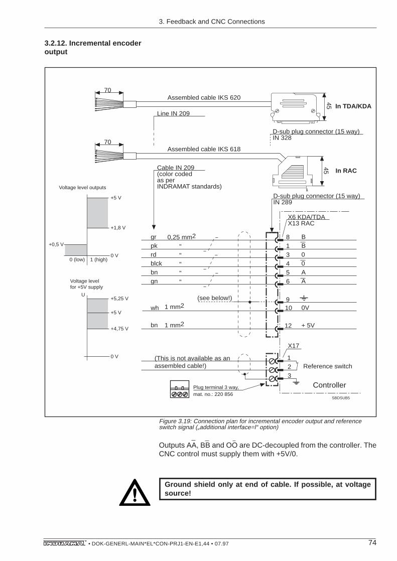
74• DOK-GENERL-MAIN*EL*CON-PRJ1-EN-E1,44 • 07.97
3.2.12. Incremental encoderoutput
Outputs AA, BB and OO are DC-decoupled from the controller. TheCNC control must supply them with +5V/0.
grpkrdblckbngn
wh
bn
""""
0,25 mm2 BB00AA
SBDSUB5
12
X17
X6 KDA/TDAX13 RAC
Plug terminal 3 way,mat. no.: 220 856
Cable IN 209(color coded as per INDRAMAT standards)
D-sub plug connector (15 way)IN 289
813456
910
12
0V
+ 5V
"
1 mm2
70
45 In RAC
In TDA/KDA
45
70Assembled cable IKS 620
Assembled cable IKS 618
Line IN 209
D-sub plug connector (15 way)IN 328
3
Controller
(This is not available as an assembled cable!)
1 mm2
1
(see below!)
Reference switch
Voltage level outputs
+5 V
+1,8 V
0 V
+0,5 V
0 (low) 1 (high)
Voltage levelfor +5V supply
+5 V
+4,75 V
0 V
U+5,25 V
Ground shield only at end of cable. If possible, at voltagesource!
IKS 620IKS 618
3. Feedback and CNC Connections
Figure 3.19: Connection plan for incremental encoder output and referenceswitch signal („additional interface=l“ option)
IKS618/IKS620

75• DOK-GENERL-MAIN*EL*CON-PRJ1-EN-E1,44 • 07.97
3.2.13. Control of the mainscontactor integrated into theRAC controller
APRACKON
2
Plug terminal, contained in elec. connecting accessories E1-RAC
1
RAC Controller
4
3
6
5
8
7
10
9
X15
ON
OFF
Bb
CS
(Mains contactor K1 opener)
OFFMains contactor
ONMains contactor
Ready
Mains contactor monitoring
(open = set up possible)
+ 24V, 1Afor ext. use
Control
(max. 24V, 1A
intermittent and
continuous)
The controller-internal mains contactor should not be usedto regularly shutdown the drives! It should only be activatedwith standing drive and controller enabler shut off!
3. Feedback and CNC Connections
Figure 3.20: Connection plan for control of the mains contactor integrated intothe RAC controller.
Do not directly connect a contactor coil via the relay contactBb, as the high intermittent currents caused by frequentswitching could overload the relay contact and cause it tofail.

76• DOK-GENERL-MAIN*EL*CON-PRJ1-EN-E1,44 • 07.97
3.3. Assembled Cable Specifi-cations
Specifications of the assembled cables for the four types of connec-tions is dependent upon the functional options of the main spindlecontroller and are summarized in tables.
Figure 3.21: Four types of assembled feedback and CNC connections
The tables indicate both the assembled cable and its construction.
direct with intermediate terminals with with plugin at the terminal strip plug design testing points
Types of feedback andCNC connections
ZuTAB
....direct connection and intermediate terminal
....plug design
....plugin testing points
Assembled specifications for...
3. Feedback and CNC Connections
Figure 3.22: Summary of assembled specifications for feedback and CNCconnections
The tables summarize the available assembled feedback and CNCcables and their significant components.
Table SummarizingAssembled Specifications

77• DOK-GENERL-MAIN*EL*CON-PRJ1-EN-E1,44 • 07.97
3. Feedback and CNC Connections

78• DOK-GENERL-MAIN*EL*CON-PRJ1-EN-E1,44 • 07.97
Ass
embl
ed c
able
for
dire
ctco
nnec
tion
Ass
embl
ed c
able
for
inte
rmed
iate
term
inal
son
term
inal
str
ip
Cab
leF
eedb
ack
or C
NC
IKS
315
IN 2
90IN
209
IN 4
01
not a
vaila
ble
alka
bf1
Inte
rfac
es o
n th
em
ain
spin
dle
cont
rolle
rC
able
des
ign
for
dire
ct c
onne
ctio
n
On
the
cont
rolle
rO
n th
eco
ntro
ller
Fee
dbac
kor
CN
C
Sta
ndar
d In
terf
aces
Mot
or fe
edba
ck c
onne
ctio
nX
3 X2
IKS
032
IKS
610
Con
trol
inpu
t, si
gnal
and
anal
ogue
out
puts
IN 3
09IN
209
IN 2
90
IN 2
71IN
293
not p
erm
itted
!
not p
erm
itted
!
IKS
610
not p
erm
itted
!
not p
erm
itted
!
Inte
rfac
es fo
r fu
nctio
nal o
ptio
ns
Type
ke
y fie
ld"s
peed
se
t-po
int"
IKS
045
IKS
612
IKO
982
X4
Aan
alog
Ddi
gita
l
LS
erco
s
IN 2
87
IN 2
91
IN 2
09
20 x
0,2
5
IN 4
18IN
414
IN 4
20
not a
vaila
ble
not a
vaila
ble
IKS
613
IKS
612
For
..
..lin
e-up
term
inal
s
For
..
..lin
e-up
term
inal
s
..lin
e-up
term
inal
s
Fee
dbac
k an
d C
NC
con
nect
ions
- d
irect
con
nect
ion
and
link
term
inal
Figure 3.23: Assembled specifications for direct connection and intermediateterminals at terminal strip allocated to the interfaces on the main spindlecontroller.
3. Feedback and CNC Connections

79• DOK-GENERL-MAIN*EL*CON-PRJ1-EN-E1,44 • 07.97
3. Feedback and CNC Connections
Typ
e k
ey
field
"a
dd
itio
na
l e
nco
de
r in
pu
t"
X5
IN 2
89
IN 2
89
IN 2
89
IN 2
89
IN 2
89
IN 2
09
IN 2
09
IN 2
09
IN 2
09
IN 2
09
IN 3
01
IN 4
01
IN 3
01
IN 4
01
IN 4
01
IKS
32
7
IKS
31
4
IKS
31
4IN
28
9IN
20
9IN
40
1
no
t p
erm
itte
d!
no
t p
erm
itte
d!
*)
no
t p
erm
itte
d!
no
t p
erm
itte
d!
*)
*)*)
P
..in
cre
me
nta
le
nco
de
r
..hig
h-re
solu
tion
mai
n sp
indl
e po
sitio
n en
code
r
..se
con
d m
oto
r fe
ed
ba
ck
*) *) *)
no
t p
erm
itte
d!
no
t p
erm
itte
d!
no
t p
erm
itte
d!
no
t p
erm
itte
d!
..in
cre
me
nta
le
nco
de
r
..hig
h-re
solu
tion
mai
n sp
indl
e po
sitio
n en
code
r
..se
con
d m
oto
r fe
ed
ba
ck
IKS
33
1IN
20
9IN
40
1
no
t a
vaila
ble
X5
a
X6
/X1
3
(*TA
/RA
C)
*)
IKS
61
4/IK
S 6
12
IN 3
51
IN 2
09
20
x 0
,25
IN 2
95
/IN
29
1
no
t p
erm
itte
d!
no
t p
erm
itte
d!
IKS
61
4/IK
S 6
12
no
t p
erm
itte
d!
no
t p
erm
itte
d!
(
)
Y
IKS
62
0/IK
S 6
18
IKS
01
5/IK
S 0
16
IN 2
09
IN 3
28
/IN
28
9
IN 2
96
/IN
29
2IN
23
4/IN
23
4IN
29
1/IN
29
1
IIn
cre
. o
utp
ut
SR
S2
32
Dd
igit.
Po
s.-s
et-
po
int
IKS
62
0/IK
S 6
18
*) / *)
no
t a
vaila
ble
*)
Le
ge
nd
:
Typ
e k
ey
field
"a
dd
itio
na
l e
nco
de
r in
pu
t"
Con
nect
edto
..
..in
cre
me
nta
le
nco
de
r
..hig
h-re
solu
tion
mai
n sp
indl
e po
sitio
n en
code
r
..se
con
d m
oto
r fe
ed
ba
ck
Con
nect
edto
..
..in
cre
me
nta
le
nco
de
r
..hig
h-re
solu
tion
mai
n sp
indl
e po
sitio
n en
code
r
..se
con
d m
oto
r fe
ed
ba
ck
Co
nn
ect
ed
to..
..in
cre
me
nta
le
nco
de
r
..hig
h-re
solu
tion
mai
n sp
indl
e po
sitio
n en
code
r
..se
con
d m
oto
r fe
ed
ba
ck
Co
nn
ect
ed
to..
Co
nn
ect
ed
to..
..in
cre
me
nta
le
nco
de
r
..hig
h-re
solu
tion
mai
n sp
indl
e po
sitio
n en
code
r
..se
con
d m
oto
r fe
ed
ba
ck
Co
nn
ect
ed
to..
IN 2
90
IN 2
90
D-s
ub
plu
g
con
ne
cto
rP
lug
co
nn
ect
or
(plu
g)
for
fee
db
ack
co
nn
ect
ion
, st
raig
ht ty
pe
Plu
g c
on
ne
cto
r (p
lug
) fo
r fe
ed
ba
ck
con
ne
ctio
n, e
lbo
w typ
eW
ire
-en
d fe
rru
leW
all
bre
akt
hro
ug
hP
lug
co
nn
ect
or
(co
up
ling
)fo
r fe
ed
ba
ck c
on
ne
ctio
n
alk
ab
f2*)
lie
ferb
ar, A
nfr
ag
e d
er
Typ
en
be
zeic
hn
un
g b
ei I
ND
RA
MA
T A
bt. E
NT
Lege
nd:
D-s
ubpl
ug c
onne
ctor
Plu
g co
nnec
tor
(plu
g)fo
r fe
edba
ck c
onne
ctio
n,st
raig
ht ty
pe
Plu
g co
nnec
tor
(plu
g)fo
r fe
edba
ck c
onne
ctio
n,el
bow
type
Mul
ti-co
re c
able
end
Wal
l br
eakt
hrou
ghP
lug
conn
ecto
r (c
oupl
ing)
for
feed
back
con
nect
ion
alka
bf2
Figure 3.23: Assembled specifications for direct connection and intermediateterminals at terminal strip allocated to the interfaces on the main spindlecontroller.
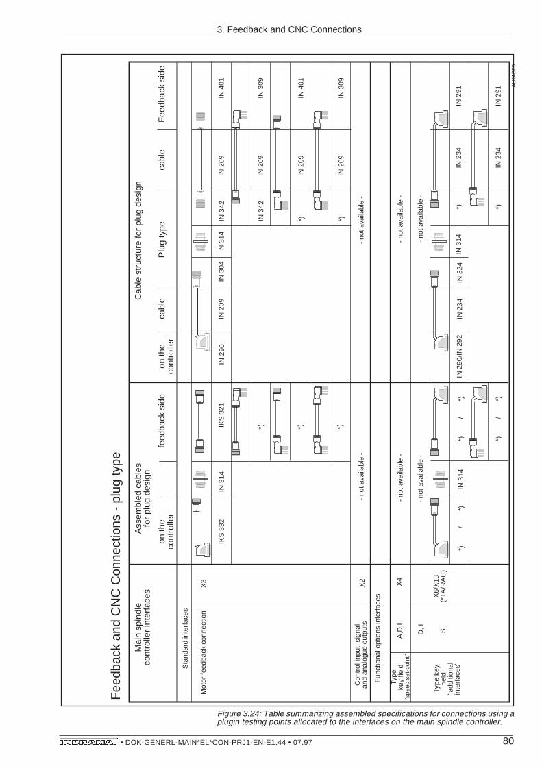
80• DOK-GENERL-MAIN*EL*CON-PRJ1-EN-E1,44 • 07.97
Figure 3.24: Table summarizing assembled specifications for connections using aplugin testing points allocated to the interfaces on the main spindle controller.
Ass
embl
ed c
able
sfo
r pl
ug d
esig
n
cabl
efe
edba
ck s
ide
IKS
332
IKS
321
IN 2
90IN
209
Mai
n sp
indl
eco
ntro
ller
inte
rfac
esC
able
str
uctu
re fo
r pl
ug d
esig
n
on th
eco
ntro
ller
Plu
g ty
peF
eedb
ack
side
Sta
ndar
d in
terf
aces
Mot
or fe
edba
ck c
onne
ctio
nX
3
*)
on th
eco
ntro
ller
IN 3
04
cabl
e
IN 3
42IN
209
IN 4
01
IN 3
42IN
209
IN 3
09
IN 3
14IN
314
*) *)
*)IN
209
IN 4
01
*)IN
209
IN 3
09
X2
Con
trol
inpu
t, si
gnal
and
anal
ogue
out
puts
- no
t ava
ilabl
e -
- no
t ava
ilabl
e -
Fun
ctio
nal o
ptio
ns in
terf
aces X
6/X
13
(*TA
/RA
C)
*)
/
*)
IN 2
90/IN
292
Type
key
fie
ld
"add
ition
al
inte
rfac
es"
SD, I
- no
t ava
ilabl
e -
- no
t ava
ilabl
e -
*)
/
*)
IN 2
34IN
324
IN 2
34*)
IN 2
91IN
314
*)
/
*)
IN 3
14
IN 2
34*)
IN 2
91
ALK
AB
F5
Type
key
field
"spe
ed s
et-p
oint
"A
,D,L
X4
- no
t ava
ilabl
e -
- no
t ava
ilabl
e -
Fee
dbac
k an
d C
NC
Con
nect
ions
- p
lug
type
3. Feedback and CNC Connections

81• DOK-GENERL-MAIN*EL*CON-PRJ1-EN-E1,44 • 07.97
Typ
e c
od
e
fie
ld
"ad
ditio
na
l e
nco
de
r in
pu
t"
X5
IKS
30
5
IKS
32
1
IN 2
89
IN 2
89
IN 2
09
IN 2
09
IKS
33
0
IKS
33
0
IKS
33
0IK
S 3
21
IN 2
89
IN 2
09
Pin
cre
me
nta
l e
nco
de
r
hig
h-r
eso
lutio
ne
nco
de
r
se
co
nd
mo
tor
fee
db
ack
*)IK
S 3
05
IN 2
90
IN 2
09
X5
a
Co
nn
ect
ed
to..
Co
nn
ect
ed
to..
IN 2
89
IN 2
89
IN 2
89
IN 2
09
IN 2
09
IN 2
09
IN 3
03
IN 3
04
IN 3
04
IN 3
03
IN 2
09
IN 2
09
IN 2
09
IN 3
05
IN 3
42
IN 3
42
IN 3
01
IN 4
01
IN 4
01
IN 2
09
IN 2
09
IN 2
09
IN 3
51
IN 3
09
IN 3
09
IN 2
09
IN 3
05
IN 3
01
IN 2
09
IN 3
05
IN 3
51
IN 3
13
IN 3
14
IN 3
14
IKS
33
0
IKS
33
0
IKS
33
0
incre
me
nta
l e
nco
de
r
hig
h-r
eso
lutio
ne
nco
de
r
se
co
nd
mo
tor
fee
db
ack
IN 3
13
IN 3
14
IN 3
14
IKS
30
8
*) *)
IN 3
13
IN 3
14
IN 3
14
IN 3
03
IN 3
04
IN 3
04
IN 3
13
IN 3
14
IN 3
14
IN 3
05
IN 3
42
IN 3
42
IN 2
89
IN 2
89
IN 2
09
IN 2
09
IKS
33
0
IKS
33
0
IKS
33
0IN
28
9IN
20
9
incre
me
nta
l e
nco
de
r
hig
h-r
eso
lutio
ne
nco
de
r
se
co
nd
mo
tor
fee
db
ack
Co
nn
ect
ed
to..
Co
nn
ect
ed
to..
IN 2
89
IN 2
89
IN 2
89
IN 2
09
IN 2
09
IN 2
09
IN 3
03
IN 3
04
IN 3
04
IN 2
09
IN 2
09
IN 2
09
IN 3
01
IN 4
01
IN 4
01
IN 2
09
IN 2
09
IN 2
09
IN 3
51
IN 3
09
IN 3
09
IN 3
13
IN 3
14
IN 3
14
IKS
33
0
IKS
33
0
IKS
33
0
incre
me
nta
l e
nco
de
r
hig
h-r
eso
lutio
ne
nco
de
r
se
co
nd
mo
tor
fee
db
ack
IN 3
13
IN 3
14
IN 3
14
*) *)
IN 3
13
IN 3
14
IN 3
14
IN 3
03
IN 3
04
IN 3
04
IN 3
13
IN 3
14
IN 3
14
IN 3
23
*) *)
*)*) *) *)
IN 3
23
*) *)
IN 3
13
IKS
30
8
*) *)
IN 3
13
IN 3
13
IN 2
09
IN 3
23
IN 3
01
IN 2
09
IN 3
23
IN 3
51 AL
KA
BF
6
Lege
nd:
D-s
ubpl
ug c
onne
ctor
Plu
g co
nnec
tor
(plu
g)fo
r fe
edba
ck c
onne
ctio
n,st
raig
ht ty
pe
Plu
g co
nnec
tor
(plu
g)fo
r fe
edba
ck c
onne
ctio
n,el
bow
type
Mul
ti-co
re c
able
end
Wal
l br
eakt
hrou
ghP
lug
conn
ecto
r (c
oupl
ing)
for
feed
back
con
nect
ion
alka
bf2
3. Feedback and CNC Connections
Figure 3.24: Table summarizing assembled specifications for connections using aplugin testing points allocated to the interfaces on the main spindle controller.

82• DOK-GENERL-MAIN*EL*CON-PRJ1-EN-E1,44 • 07.97
Figure 3.25: Table of assembled specifications for plug connections allocated tothe interfaces on the main spindle controller.
Ass
embl
ed c
able
for
plug
in te
stin
g po
ints
cabl
eF
eedb
ack
or C
NC
IKS
315
IKS
322
IN 2
90IN
209
Mai
n sp
indl
e co
ntro
ller
inte
rfac
esC
able
con
stru
ctio
n w
ith p
lugi
n te
stin
g po
ints
On
the
cont
rolle
rP
lugi
n te
stin
g po
ints
Fee
dbac
k si
de
Sta
ndar
d in
terf
aces
Mot
or fe
edba
ck c
onne
ctio
nX
3 X2
IKS
315
Con
trol
inpu
t, si
gnal
and
anal
ogue
out
puts
IKS
360
On
the
cont
rolle
r - no
t ava
ilabl
e -
- no
t ava
ilabl
e -
IN 4
01
IN 2
90IN
209
IN 4
01
cabl
e
IN 3
09IN
209
IN 4
01
IN 3
06IN
209
IN 3
09
ALK
AB
F3
Fee
dbac
k an
d C
NC
Con
nect
ions
- p
lugi
n te
stin
g po
ints
3. Feedback and CNC Connections

83• DOK-GENERL-MAIN*EL*CON-PRJ1-EN-E1,44 • 07.97
Type
key
fie
ld
"add
ition
al
enco
der
inpu
t"
X5
IKS
303
IKS
322
IN 2
89
IN 2
89
IN 2
09
IN 2
09
IKS
327
IKS
314
IKS
314
IKS
322
IN 2
89IN
209
Pin
crem
enta
l en
code
r
high
-res
olut
ion
enco
der
seco
nd m
otor
fe
edba
ck
IKS
331
IKS
303
IN 2
90IN
209
X5a
X6/
X13
(*
TA/R
AC
)
IKS
331
IN 2
09IN
290
(
)
*)
/
*)
IN 2
96/IN
292
Type
key
fie
ld
"add
ition
al
inte
rfac
e"R
S 2
32
D, I
Fun
ctio
nal o
ptio
n in
terf
aces
Type
key
fiel
d "s
peed
set
-poi
nt"
A,D
,LX
4-
not a
vaila
ble
--
not a
vaila
ble
-
Con
nect
edto
..
Con
nect
edto
..
IKS
327
IKS
314
IKS
314
incr
emen
tal
enco
der
high
-res
olut
ion
enco
der
seco
nd m
otor
fe
edba
ck
- no
t ava
ilabl
e -
- no
t ava
ilabl
e -
*)
/
*)
IN 2
89
IN 2
89
IN 2
89
IN 2
09
IN 2
09
IN 2
09
IN 2
34
IN 3
01
IN 4
01
IN 4
01
IN 3
01
IN 4
01
IN 4
01
IN 3
01 *)
IN 3
01
IN 2
09
IN 2
09
IN 2
09
IN 3
18
IN 3
06
IN 3
06
IN 3
01
IN 4
01
IN 4
01
IN 2
09
IN 2
09
IN 2
09
IN 3
18
IN 3
06
IN 3
06
IN 3
51
IN 3
09
IN 3
09
IN 2
09IN
318
IN 3
01
IN 2
09IN
318
IN 3
51
IN 2
34IN
307
IN 2
91
ALK
AB
F4
Lege
nd:
D-s
ubpl
ug c
onne
ctor
Plu
g co
nnec
tor
(plu
g)fo
r fe
edba
ck c
onne
ctio
n,st
raig
ht ty
pe
Plu
g co
nnec
tor
(plu
g)fo
r fe
edba
ck c
onne
ctio
n,el
bow
type
Mul
ti-co
re c
able
end
Wal
l br
eakt
hrou
ghP
lug
conn
ecto
r (c
oupl
ing)
for
feed
back
con
nect
ion
alka
bf2
3. Feedback and CNC Connections
Figure 3.25: Table of assembled specifications for plug connections allocated tothe interfaces on the main spindle controller.

84• DOK-GENERL-MAIN*EL*CON-PRJ1-EN-E1,44 • 07.97
Cable typ Cable Construction Diameter Bending radius in mm Weight inin mm kg/m
Fixed Flexiblerouting routing
IN 209 (2x1,0+4x2x0,25)C 8,8 ±0,3 40 90 0,102
IN 233 (2x2x0,25)C 8,3 ±0,3 80 125 0,102
IN 234 2x(2x0,22)C+2x0,5 7,0 ±0,3 45 70 0,070
IN 271 34x0,25+2x0,5 11,0 ±1,0 60 125 0,195
20 x 0,25 (20x0,25)C 9,1 ±0,4 137 182 0,153
3.4. Cable Specifications List The cable specifications used in the assembled cables are summa-rized below in table form. All necessary specifications and measure-ments are listed.
Figure 3.26: Table of cable specifications for feedback and CNC connections.
3. Feedback and CNC Connections

85• DOK-GENERL-MAIN*EL*CON-PRJ1-EN-E1,44 • 07.97
4. Installation Guide-lines
4. Installation Guidelines
Metal cable conduit
Kab_Kan
2 - 4 mm>=100 mm
Synthetic cable conduit
There must be a clearance of at least 100 mm between the powerconnections and the feedback or CNC connections if the cables arerouted parallel. Otherwise, it is necessary to separate the cableconduit with metal (see Fig. 4.1)
Figure 4.1: Routing the cables together in the cable conduit.
The guidelines outlined in the connection plans on power, feedbackand CNC connections with reference to the twisting of conductors andthe shielding of bunched conductors must be followed in order toachieve interference-free operation!
The shielding should be connected as outlined in the connectionplans. This avoids mass potential loops!
Feedback units which the main spindle controller evaluates must bemounted and electrically insulated at the machine or motor.
Do not route the feedback cables in the vicinity of high-frequencyequipment, the magnetic fields of transformers, chokes, motors andother magnetic consumers, as well as high-voltage cables , asotherwise interference could be coupled in!
Cable routing guidelines
Wiring
Feedback units

86• DOK-GENERL-MAIN*EL*CON-PRJ1-EN-E1,44 • 07.97
Figure 4.2: Degree of contamination in acc. with DIN VDE 0160.
IN172 IN217 IN172 IN217IN172 IN210IN316
V1 V1 V1V2 V2 V2
IN218
V2 V3
Machine housing Control cabinet wall
2AD...V2
IN192
Spindle housing
V1
V3
Degree of contamination Immediate environmental conditions
V1 Conductive contamination cannot occur during operation of thedrive because IP 65 type of protection is a given.
V2 Conductive contamination cannot occur during operation of thedrive (IP65). Non-conductive contamination, or light condensationof short duration can occur during installation or exchange ofdrive components.
V3 Conductive contamination can occur because contact parts areexposed and can be wetted by condensation.
Power plug connectors The dimensioning of the contact distances and leakage paths of thepower plug connectors is based on the degree of contamination asoutlined in DIN VDE 0160.
If wetting from coolants or lubricants is to be expected wheninstalling a drive or exchanging drive components, then sealthe open plug side of power connections with protectivecaps.
Only join power plug connectors if plug side is dry!
4. Installation Guidelines
Detach and join power plug connectors only when no poweris present!
If a power plug connector is used to connect 1MB framelessmotors, then do not spill coolant onto the backside of theflanged socket on either the spindle or machine housing!

87• DOK-GENERL-MAIN*EL*CON-PRJ1-EN-E1,44 • 07.97
The plug connectors of the power cable and the feedback connec-tions must be firmly screwed into place when the drive is operating!
Category IP65 protects assembled INRAMAT cables when they arefirmly screwed in and attached. This does not, however, apply to theopen side of control cabinet and housing breakthroughs as well as d-sub plug connectors!
– Do not detach the AS programming module when unit is still underpower. The knurling screw must be firmly affixed during operation!
– The d-sub plug connectors must be firmly screwed into place!
– Twist the motor power cable strands!
– The transparent panes on the safety guards on the front side of theunit must be firmly affixed during operation!
– Ground the motor on the controller and ground the controller directlyon the supply module!
– Plug the control voltage bus end plug (supply module accessories)into the last controller on the drive configuration!
– Adhere to maximum tightening torque of the stay bolts, otherwisethere is the risk of tearing!
– Plug in heatsink fan cable, if present.
– The power connection safety guards on the front of the RAC4 mustbe closed when the unit is switched on and during operation!
– Ground the motor on the controller and ground the controllerhousing to the main incoming earth terminal!
If contacts or semi-conductors are used in connection with electronicequipment and components to switch such inductive loads as chokes,contactors and relays, then these must be appropriately cleared ofinterference. If direct current is used, then this is achieved by thearrangement of freewheeling diodes, and if alternating current isused, then this is achieved with the arrangement of commercial safetyRC suppressor components situated directly at the inductivity. Do notuse varistors as protective circuits!
Only that suppression component situated directly at the inductivityserves the purpose. Otherwise an interference level is radiated whichis too high. This influences both the function of the drive and theelectronics. Other interference sources, such as high-frequencyequipment (anodized components, and similar) must be placed andwired outside of the control cabinet.
Installing Cables
Category of Protectionfor the Cable
4. Installation Guidelines
General ControllerInstallation Guidelines
Modular Drive System Installa-tion Guidelines
RAC Installation Guidelines
Measures Against Sources ofInterference from Inside theControl Cabinet

88• DOK-GENERL-MAIN*EL*CON-PRJ1-EN-E1,44 • 07.97
Controller type KDA/TDA 1RAC 2
Type key field for the controller:
Speed set-point:analog +/- 10V Adigital (16 Bit parallel) DSERCOS interface L
Additional encoder input:Without add. encoder input OWith add. encoder input for spindle feedb. or 2nd motor feedb. PWith add. encoder input and synchronous input(AS •5 and speed set-point = A) Y
Additional encoder input:Without add. encoder input OPosition set-point, digital (16 bit parallel) DSerial interface (RS 232C) SIncremental encoder output I
5. Delivery, Identifica-tion,Storage
Assembled Cables Assembled cables are rolled up and loosely packed in with thedelivery. They do have a label (cable marker), which bears the orderdesignation and the length of the assembled cable.
Figure 5.1: Label (cable marker) on INDRAMAT assembled cables.
The plug accessory sets contain the plug connector (D-sub) for theoptional interfaces of the controller. They are packed in plastic bagsand bear a packaging slip (see Figure 5.3).
The plug accessory sets are delivered in a sealed carton togetherwith single plug connectors and the controller-specific connections.
Note: The plug accessory sets are not necessarily needed (see Fig.1.2)!
INDRAMAT - Cable
No.Length: m
TSKabel
Designation: S • - • • •
Plug accessories
5. Delivery, Identification, Storage
Figure 5.2: Designations of the plug accessory sets
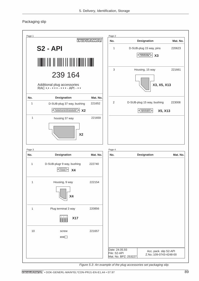
89• DOK-GENERL-MAIN*EL*CON-PRJ1-EN-E1,44 • 07.97
Page 1 Page 2
Page 3 Page 4
S2 - APINo. Designation Mat. No.
Acc. pack. slip S2-APIZ.No.:109-0743-4248-00
Date: 24.05.93File: S2-APIMat. No. BPZ: 253227
1 220623
10 221657
3 221661
D-SUB-plug 15 way, pins
screw
Housing, 15 way
1 221652
No. Designation Mat. No.
D-SUB-plug 37 way, bushing
housing 37 way1 221659
1 222154Housing, 9 way
No. Designation Mat. No.
1 222740D-SUB-plugr 9 way, bushing
No. Designation Mat. No.
X2
X2
X3, X5, X13
X3
X4
X4
2 223008D-SUB-plug 15 way, bushing
X5, X13
1 2 3
1 220856
X17
Plug terminal 3 way
Additional plug accessoriesRAC •.• - • • • - • • • - API - • •
239 164
Packaging slip
5. Delivery, Identification, Storage
Figure 5.3: An example of the plug accessories set packaging slip.

90• DOK-GENERL-MAIN*EL*CON-PRJ1-EN-E1,44 • 07.97
Individual cables are rolled up and loosely packed in with the delivery.The sequential order number is always printed on them.
Single plug connectors are packed into plastic bags. The bags havea label which indicate order number, appearance and dimensions ofthe mounted plug connector.
Single plug connectors are packed into a sealed carton along withplug accessories sets and the controller-specific connections.
The controller-specific connections are also packed in plastic bagsand labelled with the respective order number. E••-• for KDA/TDAcontrollers (depending upon the arrangement within the drive pack-age), E1-RAC for RAC controllers.
Further information about the controller-specific connections can befound in the document on the respective controller - „Project PlanningNotes“.
Note: The controller-specific connections are always required!
Assembled cables, plug accessory sets, the controller-specific con-nections, individual plug connectors and cables should be stored dryand dust-free. Permissible storage temperature range equals -30 to+85 degrees C.
Individual plug connectorsand cables
INVERP
Figure 5.4: Packing single plug connectors (example)
Leistungsstecker
5. Delivery, Identification, Storage
Controller-specific connections
Storage
Plug connector: IN 401
INDRAMAT Part No.: 230 647
bushing
View "X"
Power plug: IN 217/06
INDRAMAT Part No.: 228 351
Pin
Pin
View "X"

91• DOK-GENERL-MAIN*EL*CON-PRJ1-EN-E1,44 • 07.97
6. Customizing Specifications
Selbstkonfektionierung eines Leistungskabels
Test guidelines
Workingguidelines
Construction diagrams
with parts list1
Request construction documentation
from INDRAMAT
2Order the
individual partsand tools needed
3 Constructing the cableSoldering
(tools)Crimping
(tools)
Attaching pins, or
bushings into the insulator casing (tools)
4 Testing the cable High-voltage test
Run-through test
Insulationtest
A functioning cable without INDRAMAT guarantee
Figure 6.1: Customizing a power cable
FertigungsunterlagenWerkzeugeLötenCrimpenIsolierkörperHochspannungstestDurchgangsprüfungIsolationsprüfung
6. Customizing Specifi-cations
crimpingrun-through testhigh-voltage testinsulation testinsulator casingsoldering(tools)
Cable construction

92• DOK-GENERL-MAIN*EL*CON-PRJ1-EN-E1,44 • 07.97
Customizing amotor power cable
Allocation of motor type to the PG thread of the respective terminalbox is listed in the table outlining assembled specifications in Section2.1.3.
Figure 6.2: Screw and reduction specifications for motor power connections viaterminal boxes.
Crim
ping
cabl
e lu
gC
able
PG
RE
DK
LK
IN20
4 (f
lex.
)
Pow
er p
lug
conn
ecto
r (p
lug)
Sym
bols
:
Wire
-end
ferr
ule
Crim
ping
cabl
e lu
gF
lang
e co
nnec
tion
Pow
er p
lug
conn
ecto
r (c
oupl
ing)
PG
scr
ew c
onne
ctio
n
*) A
vaila
ble.
For
inqu
iries
on
type
info
rmat
ion
cont
act D
evel
opm
ent D
ept.,
IND
RA
MA
T.
Cro
ss s
ectio
nin
mm
2R
educ
tion
Scr
ews
IN40
4 (h
ighl
y fle
x.)
IN20
5 (f
lex.
)
IN40
5 (h
ighl
y fle
x.)
IN20
6 (f
lex.
)
IN40
6 (h
ighl
y fle
x.)
IN20
7 (f
lex.
)
IN40
7 (h
ighl
y fle
x.)
IN26
7 (f
lex.
)
IN26
8 (f
lex.
)
IN20
7 (f
lex.
)
IN40
7 (h
ighl
y fle
x.)
6 6 10 10 16 16 25 25 35 50 25 25
PG
29
PG
42
PG
48
... o
n th
eco
ntro
ller
Fra
me
less
sp
ind
le m
oto
r 1
MB
Mot
or
Term
inal
bo
x bo
lts
(dro
pped
)
(dro
pped
)
(dro
pped
)
(dro
pped
)
(dro
pped
)
(dro
pped
)
PG
29/P
G36
Mat
. no.
226
349
PG
42/P
G36
Mat
. no.
226
350
PG
48/P
G36
Mat
. no.
248
674
PG
36/P
G29
Mat
. no.
220
474
(dro
pped
)
(dro
pped
)
PG
48/P
G36
Mat
. no.
248
674
and
PG
29M
at. n
o. 2
20 8
74
PG
29M
at. n
o. 2
20 8
74
PG
29M
at. n
o. 2
20 7
42
PG
29M
at. n
o. 2
20 5
54
PG
29M
at. n
o. 2
20 4
72
PG
36M
at. n
o. 2
20 4
73
PG
29M
at. n
o. 2
20 4
72
PG
36M
at. n
o. 2
43 5
52
PG
42M
at. n
o. 2
53 4
79
PG
36M
at. n
o. 2
20 4
73
PG
29M
at. n
o. 2
20 4
72
PG
29M
at. n
o. 2
20 4
72
Ma
in s
pin
dle
mo
tor
2A
D
ReduzierungVerschraubung
6. Customizing Specifications

93• DOK-GENERL-MAIN*EL*CON-PRJ1-EN-E1,44 • 07.97
It is only possible to solder the power plug connectors – independentof cable core cross sections – in types IN172/25, IN 210/25 andIN217/25!
Pow
erpl
ugco
nnec
tor
Cab
le
PG
RE
D17
2
IN20
4 (f
lex.
)
Pow
er p
lug
conn
ecto
r (p
lug)
Sym
bols
:
Wire
-end
ferr
ule
Crim
ping
cabl
e lu
gF
lang
eco
nnec
tion
Pow
er p
lug
conn
ecto
r (c
oupl
ing)
PG
scr
ew c
onne
ctio
n
*) A
vaila
ble.
For
inqu
iries
on
type
info
rmat
ion
cont
act D
evel
opm
ent D
ept.,
IND
RA
MA
T.
Cro
ss s
ectio
nin
mm
2R
educ
tion
Bol
ts
IN40
4 (h
ighl
y fle
x.)
IN20
5 (f
lex.
)
IN40
5 (h
ighl
y fle
x.)
IN20
6 (f
lex.
)
IN40
6 (h
ighl
y fle
x.)
IN20
7 (f
lex.
)
IN40
7 (h
ighl
y fle
x.)
6 6 10 10 16 16 25 25
... o
n th
eco
ntro
ller
Mot
or
IN20
3 (f
lex.
)
IN40
3 (h
ighl
y fle
x.)
4 4
IN17
2/••
(Spe
cs a
lso
appl
y to
IN
210/
..,
IN21
7/..)
Fra
mel
ess
spin
dle
mot
or 1
MB
Red
uctio
n
PG
36/P
G29
Mat
. no.
220
474
PG
36/P
G29
Mat
. no.
220
474
PG
36/P
G29
Mat
. no.
220
474
PG
36/P
G29
Mat
. no.
220
474
PG
36/P
G29
Mat
. no.
220
474
PG
36/P
G29
Mat
. no.
220
474
PG
36/P
G29
Mat
. no.
220
474
PG
36/P
G29
Mat
. no.
220
474
PG
36/P
G29
Mat
. no.
220
474
PG
36/P
G29
Mat
. no.
220
474
PG
29M
at. n
o. 2
20 8
74
PG
29M
at. n
o. 2
20 8
74
PG
29M
at. n
o. 2
20 8
74
PG
29M
at. n
o. 2
20 8
74
PG
29M
at. n
o. 2
20 4
72
PG
29M
at. n
o. 2
21 5
54
PG
29M
at. n
o. 2
20 4
72
PG
29M
at. n
o. 2
20 4
72
PG
36M
at. n
o. 2
20 4
73
PG
29M
at. n
o. 2
20 4
72
Mai
n sp
indl
e m
otor
2A
D
6. Customizing Specifications
Figure 6.3: Specifications for bolts and reduction for motor power connectionsvia power plug connectors.

94• DOK-GENERL-MAIN*EL*CON-PRJ1-EN-E1,44 • 07.97
7. Index
7. Index
Symbole1MB connected to RAC 281MB to KDA/TDA 272AD 100 with KDA/TDA 212AD 100 and 2AD 101 connections 202AD 132 CONNECTED TO KDA/TDA 232AD 132 connected to KDA/TDA 252AD to KDA/TDA 272S 100 WITH KDA/TDA 22
AAmbient temperatures 13Analogue outputs 68AS programming module 87Autotransformer 48
BBending radius 45
CCable conduit 85Cable construction 91Category of Protection for the Cable 87CNC Connections 56Conductive contamination 86Conductor cross sections, sized 13Connecting an RAC to a three-phase mains 49Connecting components 53Connecting RAC with overvoltage surge arresters 50Connection 2AD 132 with KDA/TDA 21Connection 2AD 180 26Connection of 1MB to KDA/TDA 27Connection of 2AD 100 to KDA/TDA 20Connection plans for feedback and CNC 60Connection plans, motor-controller 19Connection with intermediate terminals, feedback/C 58Connection with plug design 58Connection with plugin testing point 59Contamination, degree of 86Control circuits RAC 75Control input 68Control voltage bus end plug 87Controller-specific connections 12Crimping 91Customizing specification 91
DDiameter 45Direct connections, feedback and CNC 57Drive configuration 87Drive shutdown 75

95• DOK-GENERL-MAIN*EL*CON-PRJ1-EN-E1,44 • 07.97
EEarth leakage circuit breaker 49Environmental conditions 86Equalizing the voltage 48
FFeedback and CNC Connections 11, 56Feedback and CNC connections 76Feedback connections 56Flanged socket 86Freewheeling diodes 87Fuse type 52
GGrounded Three-Phase Mains 48
HHeatsink fan cable 87High-resolution motor feedback 61High-voltage test 91Holding Brake 19Holding brake 9
IIKS015/IKS016 73IKS045 69IKS314 64, 66IKS610 68IKS612 70IKS614 72IKS618/IKS620 74IN 203 45IN 204 45IN 205 45IN 206 45IN 207 45IN 209 84IN 233 84IN 234 84IN 267 45IN 271 84IN 403 45IN 404 45IN 405 45IN 406 45IN 407 45Incremental encoder output 74Individual plug connectors 11, 90Installation guidelines 85Insulation test 91Insulator casing 91Interference sources inside the control cabinet 87Interference-free operation 85Isolating transformer 48
7. Index
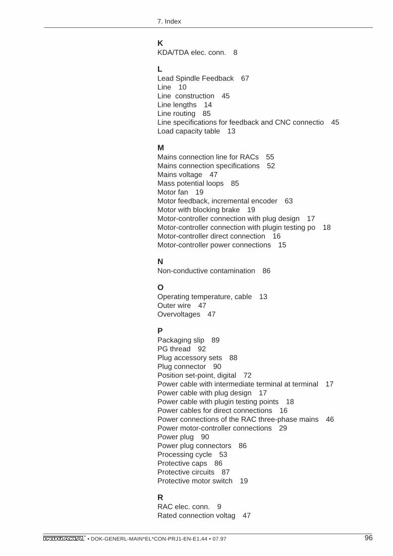
96• DOK-GENERL-MAIN*EL*CON-PRJ1-EN-E1,44 • 07.97
KKDA/TDA elec. conn. 8
LLead Spindle Feedback 67Line 10Line construction 45Line lengths 14Line routing 85Line specifications for feedback and CNC connectio 45Load capacity table 13
MMains connection line for RACs 55Mains connection specifications 52Mains voltage 47Mass potential loops 85Motor fan 19Motor feedback, incremental encoder 63Motor with blocking brake 19Motor-controller connection with plug design 17Motor-controller connection with plugin testing po 18Motor-controller direct connection 16Motor-controller power connections 15
NNon-conductive contamination 86
OOperating temperature, cable 13Outer wire 47Overvoltages 47
PPackaging slip 89PG thread 92Plug accessory sets 88Plug connector 90Position set-point, digital 72Power cable with intermediate terminal at terminal 17Power cable with plug design 17Power cable with plugin testing points 18Power cables for direct connections 16Power connections of the RAC three-phase mains 46Power motor-controller connections 29Power plug 90Power plug connectors 86Processing cycle 53Protective caps 86Protective circuits 87Protective motor switch 19
RRAC elec. conn. 9Rated connection voltag 47
7. Index

97• DOK-GENERL-MAIN*EL*CON-PRJ1-EN-E1,44 • 07.97
Rated connection voltage for control electronics 47RC suppressor components 87Reduction 92, 93Relative short-circuit voltage 53Run-through test 91
SScrews 92SERCOS Interface 71Serial interface 73Shielding of bunched conductors 85Sizing the Autotransformer 53Sizing the Isolating Transformer 54Soldering 91Soldering of power plug connectors 93Specifications of the power connection 10Speed set-point, analog 69Speed set-point, digital 70spindle feedback 66Storage 90Storage temperature 90Supply module 87Surge arresters 48, 55
TTable of power connections to the motor 29Tables, feedback and CNC conn. 76Terminal box 92Three-Phase Mains 47Tools 91
UUngrounded Three-Phase Mains 48
VVaristors 87Viewing panes 87
WWeight 45Wetting from coolants or lubricants 86Wiring 85Wye-point and outer wire grounded three-phase main 48
7. Index
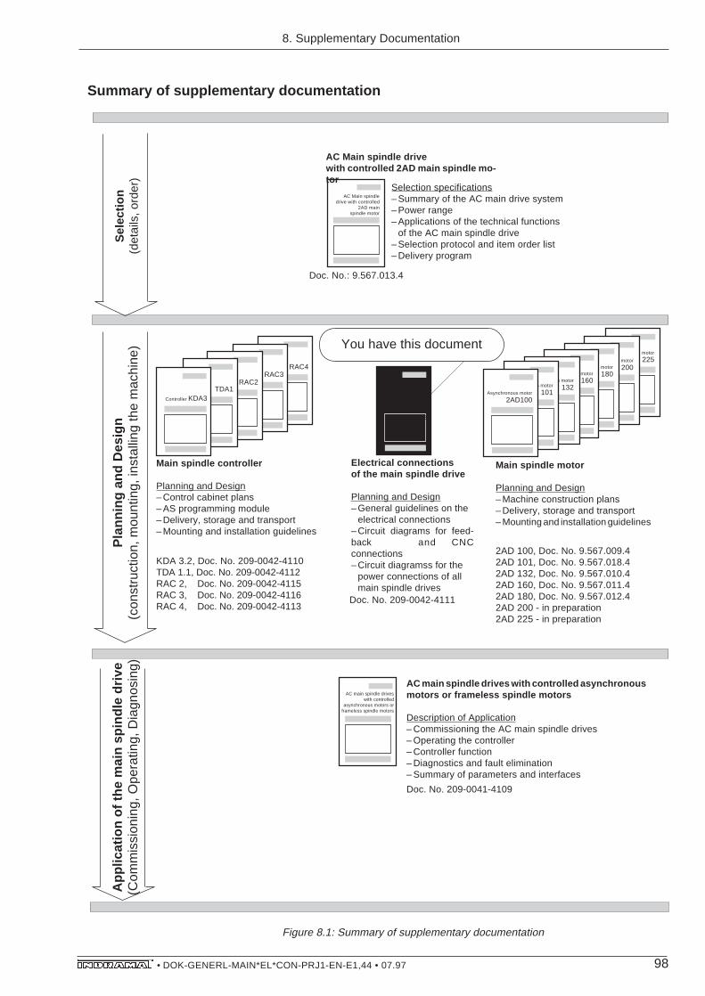
98• DOK-GENERL-MAIN*EL*CON-PRJ1-EN-E1,44 • 07.97
Summary of supplementary documentation
Figure 8.1: Summary of supplementary documentation
RAC4RAC3
RAC2TDA1
Controller KDA3
ElektrischeVerbindungen
für Haupt-spindelan-
triebe
Asynchronous motor
225
8. WeiterführendeDokumentation
Selection specifications– Summary of the AC main drive system– Power range– Applications of the technical functions
of the AC main spindle drive– Selection protocol and item order list– Delivery program
Doc. No.: 9.567.013.4
AC Main spindle drivewith controlled 2AD main spindle mo-tor
Main spindle motor
Planning and Design– Machine construction plans– Delivery, storage and transport– Mounting and installation guidelines
Main spindle controller
Planning and Design– Control cabinet plans– AS programming module– Delivery, storage and transport– Mounting and installation guidelines
KDA 3.2, Doc. No. 209-0042-4110TDA 1.1, Doc. No. 209-0042-4112RAC 2, Doc. No. 209-0042-4115RAC 3, Doc. No. 209-0042-4116RAC 4, Doc. No. 209-0042-4113
2AD 100, Doc. No. 9.567.009.42AD 101, Doc. No. 9.567.018.42AD 132, Doc. No. 9.567.010.42AD 160, Doc. No. 9.567.011.42AD 180, Doc. No. 9.567.012.42AD 200 - in preparation2AD 225 - in preparation
Electrical connectionsof the main spindle drive
Planning and Design– General guidelines on the
electrical connections– Circuit diagrams for feed-back and CNCconnections– Circuit diagramss for the
power connections of allmain spindle drives
AC main spindle driveswith controlled
asynchronous motors orframeless spindle motors
AC main spindle drives with controlled asynchronousmotors or frameless spindle motors
Description of Application– Commissioning the AC main spindle drives– Operating the controller– Controller function– Diagnostics and fault elimination– Summary of parameters and interfaces
Doc. No. 209-0041-4109
Doc. No. 209-0042-4111
8. Supplementary Documentation
Pla
nnin
g an
d D
esig
n(c
onst
ruct
ion,
mou
ntin
g, in
stal
ling
the
mac
hine
)S
elec
tion
(det
ails
, ord
er)
App
licat
ion
of th
e m
ain
spin
dle
driv
e(C
omm
issi
onin
g, O
pera
ting,
Dia
gnos
ing)
AC Main spindledrive with controlled
2AD mainspindle motor
You have this documentAsynchronous motor
200Asynchronous motor
180Asynchronous motor
160Asynchronous motor
132Asynchronous motor
101Asynchronous motor
2AD100

99• DOK-GENERL-MAIN*EL*CON-PRJ1-EN-E1,44 • 07.97
1MB- Stator1MB
- Rotor
Supplementary documentation
- high-resolution main spindle encoder • application description Doc. No. 9.552.247.4 • mounting guidelines Doc. No. 9.600.060.4- incremental encoder output IGS Doc. No. 9.568.015.4- high-resolution encoder junction HGV Doc. No. 9.568.010.4- absolute value encoder attachment for 2AD 132, 2AD 160, 2AD 180 Doc. No. 9.568.020.4
Absolutevalue
encoder2ADHGV
IGSHigh-resolutionmain spindle
position encoder
Selection specifications– Summary of the AC main drive system– Power range– Applications of the technical functions
of the AC main spiindle drive– Selection protocol and items order list– Delivery program
AC Main spindle drivewith controlled frame-
less spindle motor 1MB
1MB
Doc. No. 9.567.012.4
AC Main spindle drivewith controlled frameless spindle motor 1MB
AC main spindledrive with
changeovergearboxess 2K
AC main spindle drives with controlledasynchronous motor 2AD andchangeover planetary gearboxes 2K
Selection specifications– Summary of the
AC main drive system– Power range– Order guidelines
Frameless spindle motor
Mounting guidelines– Delivery, handling, transport– Mounting– Cooling guidelines
Planning and Design– Machine construction plans– Integrating into the cooling system– Electrical and coolant connections– Delivery
1MB 160, Doc. No. 9.576.014.41MB 200, Doc. No. 9.576.016.41MB 240/241, Doc. No. 9.576.015.41MB 310/312, Doc. No. 9.576.008.41MB 375, Doc. No. 9.576.007.4
Stator, Doc. No. 9.600.063.4Rotor, Doc. No. 9.600.062.4
Doc. No. 9.567.022.4
8. Supplementary Documentation
Pla
nnin
g an
d D
esig
n(c
onst
ruct
ion,
mou
ntin
g, in
stal
ling
the
mac
hine
)A
pplic
atio
n of
the
mai
n sp
indl
e dr
ive
(Com
mis
sion
ing,
Ope
ratin
g, D
iagn
osin
g)S
elec
tion
(det
ails
, ord
er)
Framelessspindle motor
1MB 375Frameless
spindle motor
1MB 310Frameless
spindle motor
1MB 240Frameless
spindle motor
1MB 200Frameless
spindle motor
1MB 160

Indramat
Top Related