


Languages
Pages
Legal

Instruction Manual IM02607001EEffective May 2016Supersedes June 2015
ContentsDescripoiNn Page
Installation overview . . . . . . . . . . . . . . . . . . . . . . . 2Handling and installation instructions for low-voltage switched capacitor banks . . . . . . . . . . 2Storage and handling instructions for low-voltage PFC . . . . . . . . . . . . . . . . . . . . . . . . 3Positioning . . . . . . . . . . . . . . . . . . . . . . . . . . . . . . . 4Installation and interconnect instructions . . . . . . . 5Electrical system connections . . . . . . . . . . . . . . . . 7Eaton supplied current transformer . . . . . . . . . . . . 8Startup and commissioning . . . . . . . . . . . . . . . . . . 8Eaton BLR-ACX quick commissioning guide . . . . . 9Troubleshooting . . . . . . . . . . . . . . . . . . . . . . . . . . 13Options . . . . . . . . . . . . . . . . . . . . . . . . . . . . . . . . 15Maintenance . . . . . . . . . . . . . . . . . . . . . . . . . . . . 15Warranty . . . . . . . . . . . . . . . . . . . . . . . . . . . . . . . 18
AutoVAR 600 and AutoVAR detuned fi lter automatically switched capacitor and fi lter bankinstallation operations and maintenance manual

2
Instruction Manual IM02607001EEffective May 2016
AutoVAR 600 and AutoVAR detuned fi lter automatically switched capacitor and fi lter bank
installation operations and maintenance manual
EATON www.eaton.com
m WARNINGFAILURE TO INSTALL THE AUTOVAR 600 IN ACCORDANCE WITH THESE INSTRUCTIONS MAY CAUSE DAMAGE TO THE EQUIPMENT AND/OR PERSONAL INJURY.
m WARNINGINCOMING POWER SHOULD BE DISCONNECTED BEFORE MAKING ANY WIRING CONNECTIONS.
m WARNINGAFTER ALL RIGGING, SETTING, AND WIRING HAS BEEN COMPLETED AND BEFORE THE POWER TO THE AUTOVAR IS ENERGIZED, THE INTERIOR OF THE UNIT SHOULD BE CLEARED OF ANY METAL EQUIPMENT, METAL SHAVINGS, TOOLS, AND OTHER DEBRIS.
m WARNINGWHEN THE FRONT DOOR IS OPENED WITH THE MAIN DISCONNECTS CLOSED, THE MAIN POWER BUSBARS, CAPACITOR FUSES, CAPACITOR CONTACTOR LINE SIDE, AND CONTROL TRANSFORMER FUSES ARE ENERGIZED AT LINE VOLTAGE. ONLY QUALIFIED PERSONNEL SHOULD HAVE ACCESS TO THE CABINET INTERIOR.
m WARNINGAFTER DE-ENERGIZING THE UNIT, WAIT FIVE MINUTES BEFORE OPENING THE FRONT DOOR.
Installation overviewThe installation of the AutoVAR consists of the following steps:
1. Setting the cabinet(s) in place.
2. Connecting the assembly to the electrical system.
3. Installing the current transformer on the system (checking CT polarity) and terminating secondary in the unit.
4. Programming the controller.
5. Starting and ensuring proper operation.
Handling and installation instructions for low-voltage switched capacitor banksGeneral
The following handling and installation instructions are intended to help customers install the low-voltage switched capacitor banks properly and efficiently. Handling and installation instructions are only recommendations. They do not relieve the purchaser, customer, installer, or contractor from full responsibility for proper inspection, handling, and installation. Failure by the customer to comply with handling or installation instructions will void the capacitor bank warranty.
InspecoiNn
At the time of delivery, the customer shall be responsible for inspecting all sections of the equipment for damage during transit. Both the inside and outside of the equipment must be inspected. If any damage has occurred, it should be noted on the delivery receipt prior to signing acceptance. If damage has occurred, a claim should be immediately filed by the customer with the delivering carrier. Minor paint scratch or minor dent can be touched up or repaired at the site.
MNving
1. Shipping pallets can be moved using fork lifts on both ends of the wood pallet. Do not use fork lift if the equipment has been un-mounted from the wood pallet.
2. Do not drop the equipment.
3. Do not allow hard impact from tools and handling equipment.
4. Never use cables or chains around the equipment.
5. Never fork lift equipment without the wood pallet.
6. Keep equipment upright. Do not tilt or invert the equipment.
7. Use of rollers to allow equipment to roll on base channel is permitted.
8. Weights shown on drawings are estimated weights. Refer to shipping papers for actual weights of shipping sections.

3
Instruction Manual IM02607001EEffective May 2016
AutoVAR 600 and AutoVAR detuned fi lter automatically switched capacitor and fi lter bank installation operations and maintenance manual
EATON www.eaton.com
Lifoing
1. For 78-inch-wide shipping sections (KK or double door enclosures) weighing up to 5,000 lb (2270 kg), use all four lifting eyes to lift the shipping section as shown below. The use of a spreader bar is required to avoid equipment damage.
Spreader bar
Lifting eyes use four points
<=5,000 lb
2. For 39-inch-wide shipping section (L or single door enclosures) weighing up to 3,000 lb (1,360 kg), use lines attached to all four lifting eyes to move equipment.
Lifting eyes onfour corners
3,000 lb
InsoallaoiNn
1. The equipment requires a concrete slab for continuous bottom support.
2. Locate and line-up all sections as shown on the equipment drawing. For units shipped in split sections, locate and install the provided conduit interconnecting section.
3. Once the conduit and interconnection is completed, anchor the base channel to the concrete slab with anchor bolts and hold-down hardware. Anchor bolts and hold-down hardware are to be supplied by the customer.
4. The customer can use either external anchor clips or use the holes provided in base channel to anchor this equipment.
Storage and handling instructions for low-voltage PFCAutoVAR units are shipped on pallets and are provided with lifting eyes.
All PFC units must be stored upright.
ShNro-oerm soNrage
If a capacitor unit is not energized for up to three months, store it in a climate-controlled environment with adequate air circulation so that it is protected from dirt, air born contaminants, moisture/humidity, water, and chemicals. The storage temperatures should be from –40 °C (–40 °F) to +55 °C (+131 °F). The environment humidity should be less than 70%.
If the storage area is cool and/or damp, space heaters should be provided to prevent condensation inside the automatic capacitor bank.
Evaluate and if necessary replace the dust/air filter.
LNng-oerm soNrage
Store the equipment in a dry, ventilated location protected from dirt, air born contaminants, moisture/humidity, water, and chemicals. The storage temperatures should be from 0 °C (32 °F) to 40 °C (104 °F). The environment humidity should be less than 70%.
Stored equipment could be protected by a water-resistant cover such as a tarp or plastic, providing effective protection against dust, dirt, and water, etc., taking care as to not impede the natural ventilation.
Putting a capacitor bank into service after a prolonged storage requires that the unit be subjected to INSULATION RESISTANCE AND CAPACITANCE measurements. Note: INSULATION RESISTANCE SHOULD ONLY BE PERFORMED BETWEEN TERMINAL AND GROUND. Ensure the control power fuses are disconnected/isolated during and from the test. The test readings should be at least 200 Mohm or greater. If the value is found to be lesser, take steps to trace and eliminate moisture from the unit.
Evaluate and, if necessary, clean or replace the dust/air filter.
Afoer shNro-oerm and lNng-oerm soNrage
Follow instructions of individual components such as circuit breakers.
FNr circuio breakers
Remove dust, dirt, soil, grease, or moisture from the surface of the circuit breaker using a lint-free dry cloth, brush, or vacuum cleaner. Do not blow debris into the circuit breaker. If contamination is found, look for the source and eliminate the problem.
Switch circuit breaker to ON and OFF several times to be sure that the mechanical linkages are free and do not bind. If mechanical linkages are not free, replace the circuit breaker.
With the circuit breaker in the ON position, press the PUSH-TO-TRIP button to mechanically trip the circuit breaker. Trip, reset, and switch the circuit breaker ON several times. If the mechanism does not reset each time the circuit breaker is tripped, replace the circuit breaker.
Check base, cover, and operating handle for cracks, chipping, and discoloration. Circuit breakers should be replaced if cracks or severe discoloration is found.
Check circuit breaker mounting hardware and tighten if necessary.
Check area where the circuit breaker is installed for any safety hazards, including personal safety and fire hazards.
Exposure to certain types of chemicals can cause deterioration of electrical connections.
The operation of circuit breakers with electronic trip units can be field tested using the appropriate test kit.
4
Instruction Manual IM02607001EEffective May 2016
AutoVAR 600 and AutoVAR detuned filter automatically switched capacitor and filter bank
installation operations and maintenance manual
EATON www.eaton.com
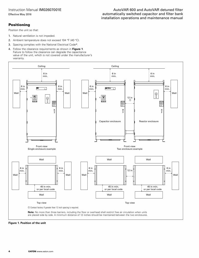
PositioningPosition the unit so that:
1. Natural ventilation is not impeded.
2. Ambient temperature does not exceed 104 °F (40 °C).
3. Spacing complies with the National Electrical CodeT.
4. Follow the clearance requirements as shown in Figure 1. Failure to follow the clearance can degrade the capacitance value of the unit, which is not covered under the manufacturer’s warranty.
aContact factory if greater than 12 inch spacing is required.
Noee:N No more than three barriers, including the floor or overhead shall restrict free air circulation when units are placed side by side. A minimum distance of 12 inches should be maintained between the two enclosures.
BEFORE SERVICING
HIGH VOLTAGECAUTION
DISCONNECT
DANGER
POWER FACTOR CORRECTION
PHASE BPHASE A PHASE C
69B1007G01
BLR-ACXPower Factor Controller
esc
R
DANGER
DISCONNECTCAUTION
HIGH VOLTAGE
BEFORE SERVICINGDISCONNECT
BEFORE SERVICING
HIGH VOLTAGECAUTION
DANGER
POWER FACTOR CORRECTION
Capacitor enclosure Reactor enclosure
PHASE A PHASE CPHASE B
BLR-CX
69B1007G01
6 inmin.
Wall Wall
Ceiling
Front viewTwo enclosure example
6 inmin.
Ceiling
6 inmin.
6 inmin.
Front viewSingle enclosure example
Top viewTop view
6 inmin.
6 inmin.
Wall Wall
6 inmin.
12 in
6 inmin.
Wall Wall
6 inmin.
6 inmin.
Wall Wall
6 inmin.12 in
45 in min.or per local code
Wall
45 in min.or per local code
Wall
45 in min.or per local code
Wall
Wall Wall Wall
a
Figure 1. PNsioiNn Nf ohe unio

5
Instruction Manual IM02607001EEffective May 2016
AutoVAR 600 and AutoVAR detuned fi lter automatically switched capacitor and fi lter bank installation operations and maintenance manual
EATON www.eaton.com
Installation and interconnect instructions for AutoVAR fi lter in two separate enclosuresWhen the AutoVAR filter bank is built in two enclosures, with capacitors in one enclosure and reactors in the other, the following instructions will guide in completing the installation and interconnection of the two cabinets.
Capacitor cabinet Reactor cabinet
Noee: N NEMAT 3R rated conduit hubs and a loose conduit nipple along with all needed conductor terminating hardware is included with the equipment. The two enclosures must be positioned next to each other and the short length of conduit placed between the two and tighten the conduit fittings to secure the conduit in place and proceed with the electrical wiring as outlined on page 6.
Figure 2. CapacioNr cabineo and reacoNr cabineo

6
Instruction Manual IM02607001EEffective May 2016
AutoVAR 600 and AutoVAR detuned filter automatically switched capacitor and filter bank
installation operations and maintenance manual
EATON www.eaton.com
The main three-phase 480 V incoming power conductors are terminated in the reactor cabinet at the power conductor mechanical lugs (see Figure 3). The lugs are sized to accommodate the maximum sized power conductors sized to the rating of the unit and calculated based on the latest edition of NECT.
A ground lug is provided for the grounding conductors in both the capacitor and reactor cabinet.
Terminal block TB1
Figure 3. Curreno oransfNrmer and pNwer wiring oerminaoiNn pNinos
The service entrance CT wiring gets connected to terminal block TB1 to terminals 1 and 2 in the capacitor cabinet. The TB1 terminals 1 and 2 also have a temporary (to be removed and stored safely) shorting pin installed that will facilitate reversal of CT lead polarities if required during commissioning and shall be removed after successful commissioning and once the CT polarities are verified.
Both power and control wiring interconnection is required between the two cabinets.
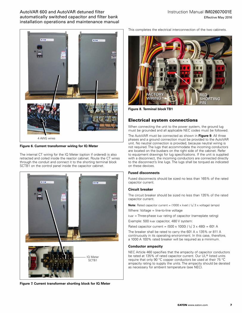
There are three 4 AWG wires per stage that need to be interconnected between the capacitor and reactor cabinet. These wires are labeled, retracted, and coiled inside the capacitor cabinet and are of sufficient length to complete the interconnection (see Figure 6). These wires are to be routed through the conduit from the capacitor enclosure to the reactor enclosure. Correctly match and terminate the labeled conductors to the appropriate reactor leads to ensure that the phase sequence is maintained. Use the included hardware to connect each power wire to the proper reactor phase lug, as determined by the labels on the wire (see Figure 4) and on the reactors. The recommended torque value is shown in Table 4.
Figure 4. Wire labels
P1 J1
Figure 5. CNnorNl wiring inoercNnnecoiNn
A control wiring harness is terminated into a male female termination plug. Complete the routing of control wiring harness through the conduit and form the connection between the P1 and J1 end of the control wiring harness (see Figure 5).
7
Instruction Manual IM02607001EEffective May 2016
AutoVAR 600 and AutoVAR detuned fi lter automatically switched capacitor and fi lter bank installation operations and maintenance manual
EATON www.eaton.com
4 AWG wires
Figure 6. Curreno oransfNrmer wiring fNr IQ Meoer
The internal CT wiring for the IQ Meter (option if ordered) is also retracted and coiled inside the reactor cabinet. Route the CT wires through the conduit and connect it to the shorting terminal block SCTB1 on the control panel inside the capacitor cabinet.
IQ MeterSCTB1
Figure 7. Curreno oransfNrmer shNroing blNck fNr IQ Meoer
This completes the electrical interconnection of the two cabinets.
Figure 8. Terminal blNck TB1
Electrical system connectionsWhen connecting the unit to the power system, the ground lug must be grounded and all applicable NEC codes must be followed.
The AutoVAR must be connected as shown in Figure 9. All three phases and a ground connection must be provided to the AutoVAR unit. No neutral connection is provided, because neutral wiring is not required. The lugs that accommodate the incoming conductors are located on the busbars on the right side of the cabinet. Refer to equipment drawings for lug specifications. If the unit is supplied with a disconnect, the incoming conductors are connected directly to the disconnect’s line lugs. The lugs shall be torqued as indicated on these devices.
Fused discNnnecos
Fused disconnects should be sized no less than 165% of the rated capacitor current.
Circuio breaker
The circuit breaker should be sized no less than 135% of the rated capacitor current.
Noee: N Rated capacitor current = (1000 x kvar) / (√ 3 x voltage) (amps)
Where: Voltage = line-to-line voltage
kvar = Three-phase kvar rating of capacitor (nameplate rating)
Example: 500 kvar capacitor, 480 V system:
Rated capacitor current = (500 x 1000) / (√ 3 x 480) = 601 A
The breaker shall be rated to carry the 601 A x 135% or 811 A continuously in its operating environment. In this case, therefore, a 1000 A 100% rated breaker will be required as a minimum.
CNnducoNr ampacioy
NEC Article 460 specifies that the ampacity of capacitor conductors be rated at 135% of rated capacitor current. Our ULT listed units require that only 90 °C copper conductors be used at their 75 °C ampacity rating to supply the units. The ampacity should be derated as necessary for ambient temperature (see NEC).

8
Instruction Manual IM02607001EEffective May 2016
AutoVAR 600 and AutoVAR detuned filter automatically switched capacitor and filter bank
installation operations and maintenance manual
EATON www.eaton.com
CT placemeno
m WARNINGFOLLOW ALL SAFETY PRECAUTIONS AND REGULATIONS FOR WORKING ON ELECTRICAL SYSTEMS RATED UP TO 600 V. ALWAYS WEAR APPROPRIATE PERSONAL PROTECTIVE EQUIPMENT (PPE). FOLLOW ALL LOCK OUT/TAG OUT PROCEDURES.
m WARNINGFAILURE TO FOLLOW THESE INSTRUCTIONS CAN RESULT IN MALFUNCTION OF THE EQUIPMENT.
• A current transformer (CT) is required for operation of an automatically switched capacitor bank. If an order for the CT was placed on Eaton to supply a current transformer with the order, it is included within your unit. Please reference AutoVAR Current Transformer Installation Manual IL157001EN for Eaton supplied CTs
• The CT is to be installed on “A-phase” of the main service entrance and wired to the terminal block TB1, terminals 1 and 2 of the capacitor bank (see Figure 7)
• The CT should always be installed upstream of the loads and capacitor bank
• CT shall not be installed on the feeder feeding the capacitor bank• CT polarity must be observed accurately for proper functioning of
the capacitor bank. H1 should always face the source (utility) side• CT rating determined by the mains service entrance rating. If exact
rating is not available, select the next higher appropriate rating• If only transformer rating is known, use the following formula to
calculate the maximum current
Current for CT rating = transformer kVA x 1000 1.732 x line voltage• The CT shall be metering class, primary rating as required, 5 A
secondary rating. The minimum Burden designation is B-0.5, as defined in IEEET Standard C57.13-2008
• The CT secondary current shall not exceed 5 A nominal. CT secondary currents of greater than 6 A can cause damage to the controller
The placement of the CT is critical to the proper operation of the AutoVAR. ImprNper lNcaoiNn and phasing Nf ohe curreno oransfNrmer (CT) causes mNre soaroup prNblems ohan any Noher errNr.
As shown in Figure 9, the CT must be placed upstream of the AutoVAR power connections preferably on phase A of the main incoming bus. In other words, place the CT so that it ‘sees’ the entire plant load, including the AutoVAR and any other capacitors. The high side of the CT (marked “H1”) must face the utility source.
After the CT has been placed on the main incoming bus, the interconnects from the CT secondary should be terminated on the terminal strip (TB) pins #1 and #2 (located on the inside left panel of the capacitor cabinet) (see Figure 8). The Terminals TB1 and 2 are factory fitted with a shorting pin (that should be safeguarded until after successful commissioning) to allow for changing any mis-wired CT wiring.
Precaution should be taken to disconnect the factory side wiring when attempting to correct the field wiring in order to avoid an open circuit on the CT secondary. Once the CT polarity and phasing has been verified, the CT shorting pin may then be removed.
CT cabling and cNnnecoiNns
CT wires should be minimum #12 AWG up to 100 ft of wire length and #10 AWG up to 150 ft. CT wires will need to be routed separately from the power conductors in a separate conduit. Shielded type cable will be required if the CT conductors are not routed in a metal conduit.
The length and gauge of wire is applicable for up to ANSI C57 B-0.5 burden. CT lead resistance will be kept to a minimum and calculated at expected overload capacity of up to 120%.
The AuoNVAR elecorical cNnnecoiNns are nNw cNmpleoe.
From service transformer or substation
B CA
AUTOVAR
TB112
H1
Ph
ase
A
Ph
ase
B
Ph
ase
C
Ph
ase
A
Ph
ase
B
Ph
ase
C
G
Ground lug
To plant load
CT locatedexternal toAutoVARPFC bank
CT installed by customer on Phase A of the facility’s service entrance/main incoming gear. The CT must measure the entire current of the facility.
Tap 1
Tap 2
Figure 9. CNnnecoiNn schemaoic
Startup and commissioningON/OFF swioch
Ensure the ON/OFF switch located on the door is in the OFF position. Before energizing the unit, please verify that all connections within the unit are secure. Tighten any loose connections to the specified values (see Table 4) using a calibrated tool. The upstream or (optional integral) disconnect or circuit breaker can now be closed to energize the unit. Once energized, turn the ON/OFF switch to the ON position and the unit is ready to begin operation as indicated by the illuminated light within the ON/OFF switch.
Cleared fuse indicaoNr lighos
The three lights on the door are cleared fuse indicator lights. These lights come on when a power fuse inside the unit is cleared. If the door of the unit is opened (with unit still energized), the cleared fuse can be identified by the red light(s) that are illuminated (a light is located next to each fuse).
Ensure that the internal and external cleared fuse indicator lights are not brightly lit before beginning the commissioning.
9
Instruction Manual IM02607001EEffective May 2016
AutoVAR 600 and AutoVAR detuned fi lter automatically switched capacitor and fi lter bank installation operations and maintenance manual
EATON www.eaton.com
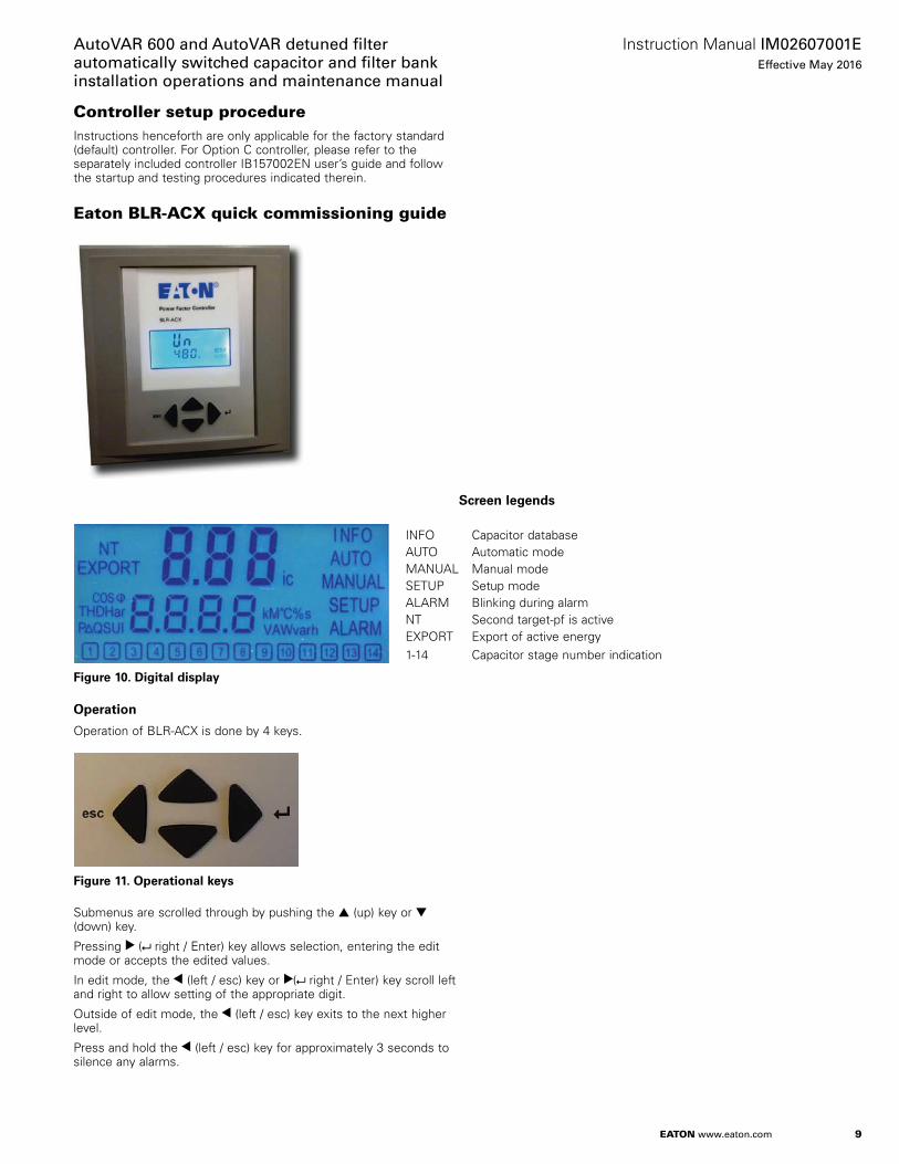
Controller setup procedureInstructions henceforth are only applicable for the factory standard (default) controller. For Option C controller, please refer to the separately included controller IB157002EN user’s guide and follow the startup and testing procedures indicated therein.
Eaton BLR-ACX quick commissioning guide
Screen legends
INFO Capacitor databaseAUTO Automatic modeMANUAL Manual modeSETUP Setup modeALARM Blinking during alarmNT Second target-pf is activeEXPORT Export of active energy1-14 Capacitor stage number indication
Figure 10. Digioal display
OperaoiNn
Operation of BLR-ACX is done by 4 keys.
Figure 11. OperaoiNnal keys
Submenus are scrolled through by pushing the ▲ (up) key or ▼ (down) key.
Pressing ▼ ( right / Enter) key allows selection, entering the edit mode or accepts the edited values.
In edit mode, the ▼ (left / esc) key or ▼( right / Enter) key scroll left and right to allow setting of the appropriate digit.
Outside of edit mode, the ▼ (left / esc) key exits to the next higher level.
Press and hold the ▼ (left / esc) key for approximately 3 seconds to silence any alarms.

10
Instruction Manual IM02607001EEffective May 2016
AutoVAR 600 and AutoVAR detuned fi lter automatically switched capacitor and fi lter bank
installation operations and maintenance manual
EATON www.eaton.com
Main screen
Measuremeno MNde
U Voltage ULL (V)▼U Voltage ULN (V)▼I Current (A)▼P active power (W)▼Q reactive power (VAR)▼∆ Q reactive power to target▼S apparent power (VA)▼THD U▼Har U (3rd harmonic U)▼Har U (5th harmonic U)▼Har U (7th harmonic U)...Har U (19th harmonic U)▼COS Phi (displacement power factor)▼PF (kW/kVA)▼APF (average power factor)▼F (frequency)▼t (temperature)▼thi (maximum temperature)▼OPh (operation hours)
Manual MNde
1 (Step 1) ▼ ON ▼ OFF▼
2 (Step 2) ▼ ON ▼ OFF▼
3 (Step 3) ▼ ON ▼ OFF...13 (Step 13) ▼ ON ▼ OFF▼
14 (Step 14) ▼ ON ▼ OFF
Basic PrNgramming MNde(100 level menu)
Un (nominal voltage ULL)▼CT (CT ratio)▼PT (PT or VT ratio)▼Ai (automatic initializing)▼PFC (power factor control on/off)▼CP1 (target power factor)▼St (switching time delay)▼Out (outputs) a
Seoup
Advanced Programming Mode (200–600 level menuspush ▼ key for 3–5 seconds
NNoee: Pressing the down arrow will take the user back to the top of the list.
NNoee: Pressing the down arrow again after 14 (Step 14) will take the user back to 1 (Step 1).
Manual screen
Seoup screen Basic prNgramming screen
aFirmware version dependent.NNoee: Pressing the down arrow key after Out will take the user back to the top of the list.
Push the right arrow key for 3–5 seconds.
Push the right arrow key for 3–5 seconds.
INFO
Push the right arrow key for 1 second.
Figure 12. Menu map

11
Instruction Manual IM02607001EEffective May 2016
AutoVAR 600 and AutoVAR detuned filter automatically switched capacitor and filter bank installation operations and maintenance manual
EATON www.eaton.com
PrNgramming ohe cNnorNller
Step 1
UpNn pNwer Nn ohe cNnorNller displays ohe exisoing pNwer facoNr value “X.XX i” and enoers ohe AuoNmaoic CNnorNl mNde.
The ‘i” at the end indicates an inductive power factor and would be appropriate for most installations. A “c” at the end indicates capacitive power factor and suggests reactive power export and may not be appropriate. Refer to the troubleshooting section for resolution steps.
Step 2
Next step is to set up the basic parameters in the controller.
From the main screen, press the ▼ (down) key to step through the “INFO”, “MANUAL” and to “SETUP” mode. When "SETUP" is shown, press the ▼ ( right /Enter) key to enter the Menu 100. Press the
▼ ( right /Enter) key and program and or verify the following values.
Un Nominal voltage (factory programmed, customer may verify)
Co CT-raoiN (facoNry seo oN 600, which cNrrespNnds oN 3000e:5 curreno oransfNrmer raoiN. Changing ohe CT raoiN will change ohe capacioNr soep sizes in 402 and ohNse values will have oN be re-prNgrammed.
Pt PT-ratio (factory programmed)
Ai Start of automatic initialization (factory programmed)
PFC PF-control ON/OFF/ HOLD (factory programmed)
CP1 Targeo-PF (cusoNmer oN prNgram)
St Switching time delay (factory programmed, customer may verify)
Out Output type of each stage (Auto/Alarm/Fixed Off/Fixed On) (factory programmed, customer may verify)
Once the Menu 100 is programmed, press the ▼ (left / esc) key three times to return to the main screen that displays the existing PF.
Overview
BLR-ACX is factory preset to the default values shown in the Table 1. Customer to program and verify the values set to meet the specific conditions of each installation.
Step 3
The next step is to verify the measured values.
From the main screen, press the ▼ ( right / Enter) key to enter the Measurement mode. See menu map for a list of designated parameters.
Press the ▼ (left / esc) key to return to the main screen that displays the existing PF.
Step 4
The final programming step is to verify the working of the capacitor bank. This is done by activating the controller in manual control mode and cycling through all the available steps.
Noee:N The steps will switch on only after the factory set capacitor stage discharge time has elapsed.
After each manual operation of the stage, the PF should change in the right direction (for example, 0.70 i >> 0.78 i >> 0.85 i…).
If the PF changes in the right direction, the capacitor bank has been correctly commissioned. If not, please refer to the troubleshooting section.
To switch the controller in manual control mode, press the ▼ (down) key to step through the “INFO” mode to “MANUAL” mode. Press and hold the ▼ ( right /Enter) key for approximately 3 seconds until “1” displays, indicating the stage number 1 is available for control.
Noee:N In manual mode, the controller freezes the stages in their existing state (ON, OFF, or HOLD). Therefore, it is important to ensure that at the end of this Step 4, the controller is returned back to the automatic control mode by pressing the ▼ (left / esc) key to return to the main screen that displays the existing PF.
After activating all available steps, one should make note of the displayed PF value as that reading should be greater than or equal to the target PF desired. If the displayed PF with the electrical system fully loaded and all steps energized is less than the target PF, then the selected capacitor bank is not sized adequately to raise the PF to the desired value. The customer should either upgrade the capacity of the capacitor bank or the target PF value should be decreased to prevent “PF alarms”.
12
Instruction Manual IM02607001EEffective May 2016
AutoVAR 600 and AutoVAR detuned filter automatically switched capacitor and filter bank
installation operations and maintenance manual
EATON www.eaton.com
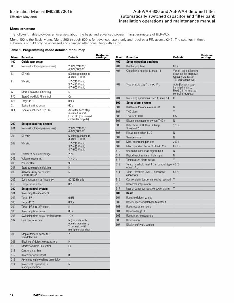
Menu sorucoure
The following table provides an overview about the basic and advanced programming parameters of BLR-ACX.
Menu 100 is the Basic Menu. Menu 200 through 600 is for advanced users only and requires a PIN access (242). The settings in these submenus should only be accessed and changed after consulting with Eaton.
Table 1. PrNgramming mNde deoailed menu map
Menu Function DefaultCustomer settings
100 Quick start setupUn Nominal voltage (phase-phase) 208 V / 240 V /
480 V / 600 VCt CT-ratio 600 (corresponds to
3000:5 CT ratio)Pt VT-ratio 1.7 (240 V unit)
3.7 (480 V unit) 4.7 (600 V unit)
Ai Start automatic initializing NPFC Start/Stop/Hold PF-control OnCP1 Target-PF 1 0.95iSt Switching time delay 60 sOut Type of each step (1,2...14) Auto (for each step
installed in unit), Fixed Off (for unused controller outputs)
200 Setup measuring system201 Nominal voltage (phase-phase) 208 V / 240 V /
480 V / 600 V202 CT-ratio 600 (corresponds to
3000:5 CT ratio)203 VT-ratio 1.7 (240 V unit)
3.7 (480 V unit) 4.7 (600 V unit)
204 Tolerance nominal voltage 20%205 Voltage measuring Y = L–L206 Phase-offset 90207 Start automatic initializing N208 Activate Ai by every start
of BLR-ACX-V N
209 Synchronization to frequency 60 (60 Hz unit)210 Temperature offset 0 °C300 Setup control system301 Switching threshold 55%302 Target-PF 1 0.95i303 Target-PF 2 0.95i304 Target-PF 2 at KW-export N305 Switching time delay 60 s306 Switching time delay for fine control 10 s307 Fine control active N (for units with
equal stage sizes), Y (for units with multiple stage sizes)
308 Stop automatic capacitor size detection
Y
309 Blocking of defective capacitors N310 Start/Stop/Hold PF-control On311 Control algorithm 1312 Reactive-power offset 0313 Asymmetrical switching time delay 1314 Switch-off capacitors in
leading conditionN
Menu Function DefaultCustomer settings
400 Setup capacitor database401 Discharging time 60 s402 Capacitor size: step 1...max. 14 Varies (see equipment
drawings for step size, typically 25, 50, or 100 kvar capacitive)
403 Type of exit: step 1...max. 14 , Auto (for each step installed in unit), Fixed Off (for unused controller outputs)
404 Switching operations: step 1...max. 14 0500 Setup alarm system501 Disable automatic alarm reset N502 THD alarm Y503 Threshold THD 6%504 Disconnect capacitors when THD > N505 Delay time THD Alarm / Temp.
threshold 2 120 s
506 Freeze exits when I = 0 N507 Service alarm N508 Max. operations per step 262 k509 Max. operation hours of BLR-ACX-V 65.5 k510 Use temp. sensor as digital input N511 Digital input active at high signal N512 Temperature alarm active Y513 Temp. threshold level 1 (fan control, type
of exit: AL) 40 °C
514 Temp. threshold level 2, disconnect capacitors
55 °C
515 Control alarm (target cannot be reached) Y516 Defective steps alarm Y517 Loss of capacitor reactive power alarm Y600 Reset601 Reset to default values602 Reset capacitor database to default603 Reset operation hours604 Reset average PF605 Reset max. temperature606 Reset alarm607 Display software version

13
Instruction Manual IM02607001EEffective May 2016
AutoVAR 600 and AutoVAR detuned filter automatically switched capacitor and filter bank installation operations and maintenance manual
EATON www.eaton.com
Troubleshooting
m CAUTIONWHILE ATTEMPTING ANY TROUBLESHOOTING STEPS THAT REQUIRE ACCESS INTO THE CAPACITOR BANK, ALWAYS FOLLOW ALL SAFETY PRECAUTIONS AND REGULATIONS FOR WORKING ON ELECTRICAL SYSTEMS. ALWAYS WEAR PROPER PPE AND FOLLOW APPROPRIATE LOCK OUT AND TAG OUT PROCEDURES.
AuoNmaoic cNnorNl mNde
The controller should display status “Auto,“which indicates that the controller is working in automatic mode. This is the desired mode of operation. If “Auto” is not displayed, then the power factor control is not working. Reasons for this are:• Manual mode is active
• Control mode has been switched off
• Temperature is too high (if temperature input is provided)
• Current from the CT is less than 15 mA
• Voltage is out of range
• Harmonic level of voltage is too high
Alarms and descripoiNn
The controller has an extended alarm system. When an alarm is active, the sign ALARM in the display blinks and an error code is shown on the screen. Possible error codes are shown in the table below.
Alarm Description
Measuring voltage is out of tolerance.
Measuring current is less than 15 mA (please check CT signal and verify that CT shorting pin has been removed).
Measuring current is too high.
Target cannot be reached.
THD U alarm (harmonic alarm).
One or more steps are defective. The defective steps are blinking together with the ALARM sign.
/ One or more steps have less than 70% of original size. Number of step and alarm text are blinking alternately.Over temperature alarm. Threshold level 2 exceeded. The steps will be switched-off step by step.
Max. allowed operating hours are reached.
/
Max. allowed number of switch cycles of one or more steps is reached.
/ Abort of automatic initialization due to unsuitable load conditions.
Curreno and vNloage mNnioNring
The controller is equipped with current and voltage monitoring to ensure it is within its operating parameters. The controller will show “I LO” alarm if there is no measured current or the magnitude sensed is less than 15 mA. If the current is greater than 6 A, the controller will show “I Hi alarm”.
If either of these alarms are displayed, check the CT current path, verifying that the correct CT ratio is selected, the CT is in the correct position, and the current input and shorting jumpers at the terminal block are removed.
The allowed range of voltage depends on nominal voltage. When nominal voltage is out of range, “U Alarm” is shown. If this alarm is seen, then the setting of nominal voltage has to be adjusted. Nominal Voltage is measured and entered phase to phase.
CapacioNr soage daoabase
A step fault (“STEP / FLTY”) or step low (“SPL”) alarm indicates problems with the sensed capacitor size. To check the capacitor stages, switch the controller into the INFO mode by pressing the ▼ (down) key. In the INFO submenu, by pressing the ▲ (up) or ▼ (down) key, the steps can be chosen and once the steps are indicated in the display, pressing the ▼ ( ) (right/enter) key displays the information for the selected steps.
CC C INFO 50 kVAR a
▼ INFO 99.9% a
▼ OC INFO 10.12 k a
▼ i INFO AUTO a
actual power of step
percentage actual to nominal power
number of operations
step type
It’s possible to have capacitive steps as well as inductive steps. Ensure the steps show capacitive (“C”) kvar).
High oemperaoure alarm
1. Replace dust filters (Catalog Number AUTOVAR6FX8).
2. Verify proper operation of fans.
3. Verify that measured ambient temperature does not exceed 40 °C (104 °F).
4. Check for external sources of heat such as direct sunlight.
PFC alarm
Possible reasons could be:
1. Insufficient capacitance available or target PF set too high.
2. Capacitor stages deteriorated.
3. Capacitor stages sensed or set incorrectly (both in terms of type (inductive or capacitive) and value (100 kvar instead of 50 kvar).
PF value incNrreco, decreases as soeps are added Nr shNws X.XX“c”
1. CT polarity is incorrect.
2. CT leads are swapped.
3. CT is not mounted on A phase.
Adjust the Phase-Offset menu parameter according to the following chart.
CT installed phase (with respect to incoming AutoVAR bus) CT polarity
Controller phase-offset
A Straight 90A Reverse 270B Straight 330B Reverse 150C Straight 210C Reverse 30

14
Instruction Manual IM02607001EEffective May 2016
AutoVAR 600 and AutoVAR detuned filter automatically switched capacitor and filter bank
installation operations and maintenance manual
EATON www.eaton.com
PF value shNws unioy Nr dNes nNo change even afoer soeps are engaged
1. Location of CT is incorrect. Ensure that the CT is connected electrically ahead of the capacitor bank (at the service entrance panel or switchgear) and is not connected on the feeder that supplies power to the capacitor bank.
2. Steps have failed.
IncNrreco measuremeno values
1. Check that CT and PT ratios are programmed correctly in Menu 100.
2. Check that Nominal voltage is programmed correctly in Menu 100.
CNnorNller nNo swioching Nn addioiNnal soeps and dNes nNo reach oargeo PF
This usually happens when the amount of capacitance available does not match the amount of kvar required. this can happen especially in low load situations when the amount of kvar required is very low compared to the smallest available step size (for example, total kvar required is 12 kvar and the smallest step size available is 60 kvar). The controller will not bring on any step to prevent overcompensation.
1. Check that the sensed and programmed capacitor step sizes are set and match the actual value.
2. Check that the setting in 314 is set to N.
3. Check the amount of shortfall kvar (▲Q) in the measurement menu and program this value in menu 312.
4. If all above fails, one may need to install smaller kvar size steps to allow the controller to switch them during low demand.
BLR-ACX cNnorNller oechnical daoa
Description Specification
Measuring and supply voltage
90–550 Vac, single-phase, 45–65 Hz, 5 VA, max. fuse 6 A VT-ratio from 1.0 to 350.0
Current measuring 15 mA – 6 A, single-phase, burden 20 mohm, ct-ratio from 1 to 9600
Control exits Up to 14 relays, n/o, with common point, max. fuse 6 A breaking capacity: 250 Vac / 5 A
Temperature measuring By NTCAlarm contact Relay, volt free, life contact, max. fuse 6 A,
breaking capacity: 250 Vac / 5 AInterface TTL, rearAmbient temperature Operation: –20 °C to 70 °C, storage: –40 °C to 85 °CHumidity 0–95%, without moisture condensationVoltage class II, dirt class 3 (DIN VDE 0110, part 1 / IEC 60664-1)Conformity and listing
, ,
Connection Pluggable terminal block, screw type max. 4 qmmCase Front: instrument case PC/ABS (UL94-VO), Rear: metalProtection class Front: IP50, (IP54 by using a gasket), Rear: IP20
ReorNfio insoallaoiNns wioh BLR-ACX cNnorNller
Please retain and follow all instructions and safety precautions during and after installation.
1. Compare voltage and current ratings of BLR-ACX with data of mains and installation.
2. Mount the relay in the control panel with the two mounting clips.
3. Connect protection GROUND to PE connection of metal case.
4. BLR-ACX is to be connected according to the wiring diagram.
5. Ensure that the short-link for CT input signal is removed.
6. Typical wiring diagram of the controller is shown below. This may not match the existing installation. Please consult Eaton for retrofitting this into existing Eaton capacitor banks.
load
K L Um1Um2 AM
MS 1 14 1-14T1 T2
externaltemperature sensor
or temperature switch(parallel use of sensorand switch is possible)
up to 14control exits
control exits canbe parametered for fan control
signal:in order
(life-contact)
K1 K14
K1-K14
L1
L2
L3
N
PE
BLR-CX
TTLInterface
X/1A or X/5A
10mA - 6A 90V - 550V
power-input utility
Figure 13. Wiring diagram
TrNubleshNNoing
Symptom Correction
No control power Check primary control fuses (three fuses located in fuse holder) and secondary fuse located on control transformer.Check disconnect or circuit breaker is ON.Check GFCI located on control panel inside cabinet.Check the reactor thermal switches status (open if operated, closed if healthy).
Displayed power factor is obviously wrong or decreases as stages engage
CT secondary current is too low (check CT tap setting and plant load).CT polarity is incorrect or leads are reversed.
Stages do not engage and target power factor has not been reached
Confirm that an inductive power factor is being displayed (i.e., ‘i.73’, not ‘c.73’).Confirm that the required reactive power is at least 60% of the smallest step size available for switching.Confirm availability of capacitor stages and there is no stage alarm.Confirm “AUTO” is being displayed on the controller.
Blown fuse lights on front cabinet are lit (w/no blown fuses)
Check 3 primary control fuses (on control panel) if check system voltage matches the nameplate voltage.
Displayed power factor does not change as stages engage
Review ‘Current transformer placement and connection’
Controller troubleshooting Refer to “Controller setup procedure” section.

15
Instruction Manual IM02607001EEffective May 2016
AutoVAR 600 and AutoVAR detuned filter automatically switched capacitor and filter bank installation operations and maintenance manual
EATON www.eaton.com
Fuse (clearing)
Capacitor fuses may clear for many reasons. An occasional cleared fuse may be the result of a switching ‘spike’, lightning strike, or other electrical disturbance. However, frequent fuse clearing may be a sign of a more serious problem. Please contact your Eaton representative or Eaton’s Technical Resource Center at 1-800-809-2772 option 4, sub-option 2 for assistance if frequent fuse clearing occurs.
Temperature control
The controller is fitted factory default with an ambient temperature alarm and trip option. The controller is also fitted with a non-reversing temperature sticker that helps monitor the highest reached temperature inside the cabinet.
The alarm and trip options are field adjustable and are set at the values shown in the controller set point table (see Table 1).
When the cabinet temperature exceeds the trip set point, the controller will shut down all the stages until the cabinet temperature falls below the trip set point, at point which the controller will resume the control of the stages.
If the PFC unit appears not to bring on any stages or is otherwise inoperable, check the temperature indicator on the back of the controller and verify that the temperature is within the specified limits of the unit.
OptionsRemNoe alarm relay (NpoiNn cNde A)
Remote alarm relay provides a single Normally Open volt-free 250 V / 5 A contact wired to a terminal block for customers’ use.
CNmmunicaoiNns cNnorNller (NpoiNn cNde C)
Selecting option code C provides the user with our advanced controller that is equipped with ModbusT RTU RS-485 communications capability and additional advanced features. See IB157002EN.
HOA swioches (NpoiNn cNde H)
The HOA switches provide external control of the capacitor stages. The following switch positions are available:• Hand—turns stage on• Off—turns stage off• Auto—controller activated stages
Circuio breaker (NpoiNn cNde M Nr M1)
The trip settings on the circuit breakers shall be set in accordance with the NEC and coordination requirements within the facility.
IQ Meoer (NpoiNn cNde Q)
The IQ 250 Meter provides an electronic panel meter to those who wish to monitor various electrical parameters of the capacitor bank. The IQ Meter cannot display the system parameters and thus should not be used for displaying the system parameters such as power factor, power, voltage, current, etc. For operation of the IQ Meter, please refer to the IQ manual.
Deouned (applies oN AuoNVAR filoers Nnly, cNde Y)
Detuned code Y supplies a 4.2 (5.67% reactors) tuned unit instead of 4.7 (4.53% reactors).
CusoNm NpoiNns (NpoiNn cNde S)
Non-standard options including remote shutdown command, external interlock, etc. Consult with factory.
Weaoher-resisoano (NpoiNn cNde W)
Allows the enclosure ingress protection rating to be NEMA 3R.
MaintenanceThe AutoVAR requires very little maintenance to operate reliably. However, please follow the Startup and Maintenance Schedule included.
De-energize unio befNre wiohdrawing oray oN access duso filoer.
NOTICEIF ANY LARGE NONLINEAR LOADS (ADJUSTABLE SPEED DRIVES, VFDS, DC DRIVES, BATTERY CHARGERS, ETC.) ARE INSTALLED IN THE PLANT AFTER INSTALLATION, PLEASE CONTACT YOUR EATON SALES REPRESENTATIVE TO ENSURE THAT THE CAPACITOR WILL NOT BE ADVERSELY AFFECTED.
Dust filters—Strata density panel air filters UL Class 2— 1-inch H x 25 inches W x 18-1/2 inches D.
The dust filter is located at the bottom of the equipment enclosure and does not require opening the cabinet door.
Dust filters should be replaced at least quarterly as suggested in our preventive maintenance guidelines and more often if the unit is located in a polluted environment. Eaton stocks and sells replacement air filter part number AUTOVAR6FX8. Contact your Eaton distributor or sales team to order.
Figure 14. Duso filoer lNcaoiNn

16
Instruction Manual IM02607001EEffective May 2016
AutoVAR 600 and AutoVAR detuned filter automatically switched capacitor and filter bank
installation operations and maintenance manual
EATON www.eaton.com
Table 2. LNw-vNloage capacioNr bank soaroup inspecoiNn and mainoenance schedule
CUST
OM
ER:
UN
IT S
ERIA
L N
UM
BER
:
Qtr:
Ever
y 3
mon
ths
Sem
i: Ev
ery
6 m
onth
sAn
n: E
very
12
mon
ths
CCl
ean
PTo
uch-
up P
aint
FCh
eck
for O
pen/
Dam
age
Fuse
RRe
plac
e pa
rts o
r com
pone
nt
IIn
spec
tion
of C
ompo
nent
/Equ
ipm
ent
SAp
ply
Silic
one
Caul
k (O
utdo
or U
nit)
LLu
bric
ate
TTe
st c
ompo
nent
OTo
rque
Con
nect
ions
VVe
rify
Oper
atio
n
Rout
ine
Serv
ice
Sche
dule
Yea
rs F
rom
Inst
alla
tion
Dat
e
Com
pone
ntSt
artu
pQ
uart
erly
Sem
i-A
nnua
llyA
nnua
lly2.
55
7.5
1012
.515
17.5
20
Date
of S
ervi
ce:
Serv
ice
Perfo
rmed
By:
Air F
ilter
sI
R
Alar
m In
dica
tion
VV
Bus
Conn
ectio
nsO
OO
OO
OO
OO
Bush
ings
II,
C
Cabl
e Te
rmin
atio
nsO
IO
OO
OO
OO
O
Capa
cito
rI
IT
TT
T, R
Cont
rol &
Tim
ing
Rela
ysV
TT
TT,
R
Cont
rolle
rV
VT
TT
T, R
Corro
sion
/ Co
nden
satio
nI
I, P
CT C
ircui
tV
VT
Encl
osur
eI,
S, P
I, P
SS
Fans
VI
I, V
TR
Fuse
sT
FR
Inse
ct S
cree
nsI,
CC
CC
CC
CC
C
Insu
lato
rs a
nd S
uppo
rtsI,
CI,
C
Pow
er &
Con
trol C
able
sI
IT
T
Reac
tor
II,
CT
T
Cont
acto
rsV
VT
T, R
Test
CT
Pola
rity
(opt
iona
l)T
(Per
form
insp
ectio
n an
d m
aint
enan
ce s
ervi
ce p
er a
bove
sch
edul
e an
d re
cord
ser
vice
dat
es)
17
Instruction Manual IM02607001EEffective May 2016
AutoVAR 600 and AutoVAR detuned filter automatically switched capacitor and filter bank installation operations and maintenance manual
EATON www.eaton.com
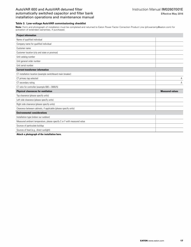
Table 3. LNw-vNloage AuoNVAR cNmmissiNning checklisoNoee:N Form and photograph of installation must be completed and returned to Eaton Power Factor Correction Product Line ([email protected]) for
activation of extended warranties, if purchased.
Project information
Name of qualified individual
Company name for qualified individual
Customer name
Customer location (city and state or province)
Unit catalog number
Unit general order number
Unit serial number
Current transformer information
CT installation location (example switchboard main breaker)
CT primary tap selected A
CT secondary rating A
CT ratio for controller (example 600 = 3000/5)
Physical clearances for ventilation Measured values
Top clearance (please specify units)
Left side clearance (please specify units)
Right side clearance (please specify units)
Clearance between cabinets, if applicable (please specify units)
Environmental considerations
Installation type (indoor our outdoor)
Measured ambient temperature, please specify C or F with measured value
Sources of particulate buildup
Sources of heat (e.g., direct sunlight)
Attach a photograph of the installation here.
18
Instruction Manual IM02607001EEffective May 2016
AutoVAR 600 and AutoVAR detuned filter automatically switched capacitor and filter bank
installation operations and maintenance manual
EATON www.eaton.com
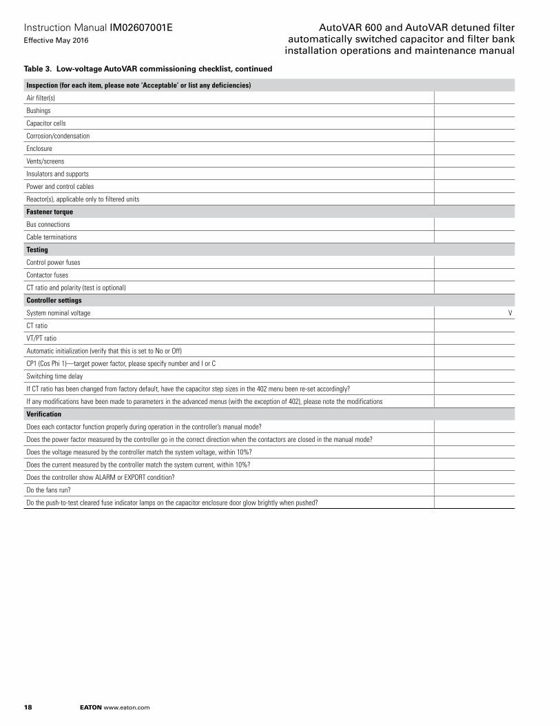
Table 3. LNw-vNloage AuoNVAR cNmmissiNning checkliso, cNnoinued
Inspection (for each item, please note ‘Acceptable’ or list any deficiencies)
Air filter(s)
Bushings
Capacitor cells
Corrosion/condensation
Enclosure
Vents/screens
Insulators and supports
Power and control cables
Reactor(s), applicable only to filtered units
Fastener torque
Bus connections
Cable terminations
Testing
Control power fuses
Contactor fuses
CT ratio and polarity (test is optional)
Controller settings
System nominal voltage V
CT ratio
VT/PT ratio
Automatic initialization (verify that this is set to No or Off)
CP1 (Cos Phi 1)—target power factor, please specify number and I or C
Switching time delay
If CT ratio has been changed from factory default, have the capacitor step sizes in the 402 menu been re-set accordingly?
If any modifications have been made to parameters in the advanced menus (with the exception of 402), please note the modifications
Verification
Does each contactor function properly during operation in the controller’s manual mode?
Does the power factor measured by the controller go in the correct direction when the contactors are closed in the manual mode?
Does the voltage measured by the controller match the system voltage, within 10%?
Does the current measured by the controller match the system current, within 10%?
Does the controller show ALARM or EXPORT condition?
Do the fans run?
Do the push-to-test cleared fuse indicator lamps on the capacitor enclosure door glow brightly when pushed?

19
Instruction Manual IM02607001EEffective May 2016
AutoVAR 600 and AutoVAR detuned fi lter automatically switched capacitor and fi lter bank installation operations and maintenance manual
EATON www.eaton.com
Table 4. TNrque charo
Location identifier
Torque table
Torque value Remarks
1 Customer incoming conductor to mechanical lug (customer wiring) 275 in-lb For lug size suitable to accommodate conductors maximum up to 350 kcmil375 in-lb For lug suitable to accept conductors greater than 350 kcmil up to 750 kcmil
2 Mechanical lug to bus bar (factory wiring) 20 ft-lb3 4 AWG wire terminated onto bus (factory wiring) 60 in-lb4 4 AWG wire terminated onto reactor (if applicable) (factory wiring) 60 in-lb5 4 AWG wire terminated onto fuse (factory wiring) 60 in-lb Bottom terminals6 4 AWG (pigtail) wire terminated onto contactor (factory wiring) 45 in-lb Bottom terminals7 Capacitor mounting M8/M10 stud (factory wiring) a 14.8 ft-lb Stud on bottom of capacitor8 8 AWG wires to capacitor contactors (factory wiring) a 22 in-lb Top terminals9 8 AWG wires to contactors (factory wiring) a 45 in-lb Top terminals10 Nest assembly mounting bolt (not a factory torqued live part) 20 ft-lb Rear of nest11 Reactor mounting bolt (not a factory torqued live part) 20 ft-lb
a Customer wiring if expanding unit in field.
WarrantyStandard warranty is 1 year, parts only, against manufacturing defects for entire unit. For units with standard-duty capacitor cells, the capacitor cells provided with the unit have a standard 2-year warranty against manufacturing defects, parts only. For units with heavy-duty capacitor cells, the capacitor cells have a standard 5-year warranty against manufacturing defects, parts only.

EaoNn1000 Eaton BoulevardCleveland, OH 44122United StatesEaton.com
© 2016 EatonAll Rights ReservedPrinted in USAPublication No. IM02607001E / Z18244May 2016
Eaton is a registered trademark.
All other trademarks are property of their respective owners.
AutoVAR 600 and AutoVAR detuned filter automatically switched capacitor and filter bank
installation operations and maintenance manual
Instruction Manual IM02607001EEffective May 2016
For technical support and application engineering assistance, please contact Eaton’s TRC at1-800-809-2772 option 4, option 2or email [email protected]
This instruction manual is published solely for information purposes and should not be considered all-inclusive. If further information is required, you should consult an authorized Eaton sales representative.
The sale of the product shown in this literature is subject to the terms and conditions outlined in appropriate Eaton selling policies or other contractual agreement between the parties. This literature is not intended to and does not enlarge or add to any such contract. The sole source governing the rights and remedies of any purchaser of this equipment is the contract between the purchaser and Eaton.
NO WARRANTIES, EXPRESSED OR IMPLIED, INCLUDING WARRANTIES OF FITNESS FOR A PARTICULAR PURPOSE OR MERCHANTABILITY, OR WARRANTIES ARISING FROM COURSE OF DEALING OR USAGE OF TRADE, ARE MADE REGARDING THE INFORMATION, RECOMMENDATIONS, AND DESCRIPTIONS CONTAINED HEREIN. In no event will Eaton be responsible to the purchaser or user in contract, in tort (including negligence), strict liability or otherwise for any special, indirect, incidental or consequential damage or loss whatsoever, including but not limited to damage or loss of use of equipment, plant or power system, cost of capital, loss of power, additional expenses in the use of existing power facilities, or claims against the purchaser or user by its customers resulting from the use of the information, recommendations and description contained herein.
Top Related