


![Human Arm Imitation · Human-robot skeleton mapping Robot Joint Angles D-H Parameters [2] Human Arm Robot Arm References [2] [4] Industrial Robots can now be trained and controlled](https://static.fdocuments.us/doc/165x107/5f76b9ded7aa2d6f12317b91/human-arm-imitation-human-robot-skeleton-mapping-robot-joint-angles-d-h-parameters.jpg)
Languages
Pages
Legal

- 1 -
ROBOT ARM CHASSIS
© AREXX - THE NETHERLANDS V0513
MOUNTING INSTRUCTIONS: Model RA2-CH2
EDUCATIONAL ROBOT

- 2 -
AREXX and ROBOT ARM are registered trademarks of AREXX Engineering - HOLLAND. © English translation (March 2013): AREXX Engineering (NL).This manual is protected by laws of Copyright. Any full or partial reproduction of the contents are forbidden with-out prior written authorization by the European importer. : AREXX Engineering - Zwolle (NL).
Manufacturer and distributor cannot be held responible for any damage resulting from mishandling, mounting mistakes or disrespect of the instructions contained in the manual. Subject to changes without prior notice.
Technical mounting support:
WWW.AREXX.COM
WWW.ROBOTERNETZ.DEManufacturer:AREXX EngineeringDAGU HI-TECH
European importer:AREXX EngineeringZWOLLE The Netherlands
© AREXX Holland and DAGU China © English translation: AREXX - The Netherlands
1. Product description ROBOT ARM 5 2. Required tools 7 3. Part list 8 4. Mounting instructions 10
Table of Contents

- 3 -
Impressum©2007 AREXX EngineeringNervistraat 16 8013 RS Zwolle The Netherlands
Tel.: +31 (0) 38 454 2028 Fax.: +31 (0) 38 452 4482
E-Mail: [email protected]
This manual is protected by the laws of Copyright. It is forbidden to copy all or part of the contents without prior written authorization!
Product specifications and delivery contents are subject to changes. The manual is subject to changes without prior notice.
You can find free updates of this manual on
http://www.arexx.com/
“Robot Arm PRO und -Hobby” are registered trademarks from AREXX Engineering.All other trademark are the property of their owners. We are not responsible for the contents of external web pages that are mentioned in this manual!
Information about limited warranty and responsibility The warranty granted by AREXX Engineering is limited to the replacement or repair of the Robot Arm and its accessories within the legal warranty period if the default has arisen from production errors such as mechanical damage or missing or wrong assembly of electronic components except for all components that are connected via plugs/sockets.The warranty does not apply directly or indirectly to damages due to the use of the robot. This excludes claims that fall under the legal prescription of product responsibility.
The warranty does not apply in case of irreversible changes (such as soldering of other components, drilling of holes, etc.) of the Robot Arm or its accessories or if the Robot Arm is damaged due to the disrespect of this manual!
The warranty is not applicable in case of disrespect of this manual! In addition, AREXX Engineering is not responsible for damages of all kinds resulting from the disrespect of this manual! Please adhere above all to the „Safety recommendations“ in the Robot Arm manual.
Please note the relevant license agreements on the CD-ROM!
IMPORTANTPrior to using this robot arm for the first time, please read this manua thoroughly up to the end! They explain the correct use and inform you about potential dangers! Moreover they contain important information that might not be obvious for all users.
Important safety recommendation
This module is equipped with highly sensitive components. Electronic components are very sensitive to static electricity discharge. Only touch the module by the edges and avoid direct contact with the components on the circuit board. Please do never overload the servo’s

- 4 -
Symbols
This manual provides the following symbols:
The “Attention!” Symbol is used to mark important details. Neglecting these precautions may damage or destroy the ro-bot and/or additional components and additionally you may risk your own health or the health of other persons!
The “Information” Symbol is used to mark useful tips and tricks or background information. In this case the informa-tion is to be considered as “useful, but not necessary”.
Safety recommendations
- Check the polarity of the batteries or power supply.- Keep all products dry, when the product gets wet remove the batteries or power directly.- Remove the batteries or power when you are not using the product for a longer period.- Before taking the module into operation, always check it and its cables for damage.- If you have reason to believe that the device can no longer be operated safely, disconnect it immediately and make sure it is not unintentionally operated.- Consult an expert if you are unsure as to the function, safety or connection of the module.- Do not operate the module in rooms or under unfavourable conditions.- Do not overload the servo’s - This module is equipped with highly sensitive components. Electronic components are very sensitive to static electricity discharge. Only touch the module by the edges and avoid direct contact with the components on the circuit board.
Normal use
This product was developed as an experimental platform for all persons which are interested in robotics. Main goal is to learn how you can program the device in C-langue. This product is not a toy; it is not suitable for children under 14 years of age!
This robot arm is also not an industrial robot arm, with industrial specifications and preformance!
It may only be used indoors. The product must not get damp or wet. Also be carful with condence when you take it from a cold to an warm room give it time to adapt on the new coditions before you use it.
Any use other than that described above can lead to damage to the product and may involve additional risks such as short circuits, fire, electrical shock etc.
Please read all the safety instructions of this manual.

- 5 -
1. PRODUCT DESCRIPTION ROBOT ARM
The ROBOT ARM is an affordable robot for the hobbyist. It is ideally suited to learn the basics of electronics, mechanics and program-ming.
Contents of the package:
- Complete Robot Arm construction set (mechanics WITHOUT electronics)- CD-ROM containing all manuals
1.2. Specifications:
- 4 mini-servos DGServo 12g - 2 maxi-servos DGServo S07NF STD - Plastic arm and metal chassis - Arm length: 260 mm - Height: 320 mm - Base diameter: 150 mm - Lifting power 75 Gramms
* The right of return does not apply after opening the plastic bags containing parts and components.* Read the manual thoroughly prior to assembling the unit.* Be careful when handling tools. * Do not assemble the robot in presence of small children. They can get hurt with the tools or swallow small components and parts. * Check the correct polarity of the batteries.* Make sure that batteries and holder remain always dry. If the ROBOT ARM gets wet, remove the batteries and dry all parts as thoroughly as possible.
* Remove the batteries if the ROBOT ARM will not be used for more than one week.
Warnings

- 6 -
N e e d l e - n o s e pliers
Sidecutter
2. Required tools
Screwdriver set
Selftapping screws (Parker)
Selftapping screws behave like wood screws i.e. they cut a thread into the material in a rotating motion that functions like a nut. To this end, this type of screw has a larger thread and a sharper tip as a normal screw.
Selftapping screws have a cutout at the top that makes it easier to drill into the material. The best way to fasten such a screw is:
If the screws are loosened and tightened too often, the hole enlargens gradually and the screw doesn’t fit anymore properly.
1 Drive the screw into the material2 Slightly loosen the screw3 Tighten the screw again
The set includes a double open-end wrench. Use this wrench for the M2 and M3 nuts. You can use this wrench instead of pliers.
Double open-end wrench:
Locknut
Locknut
Do not force the screws otherwise the plastic may crack.
Fastening a locknut
Double open-end wrench
IncludedIncluded
Screwdriver
1
32

- 7 -
3. PART LIST Servomotor
O 4 x Mini DGServo 12gO 2 x Maxi DGServo S07NF STD
Servo disc
O 4x
O 4x
O 1x
Spacer for Servo Cover for servo holder
O 2x
Disk with axis
Holder formaxi-servo
Servo holder -dual
O 1xO 1xO 4x
Cover for maxi-servo holder
O 1xO 2x
Servolever
Spacer M3x6
Spacer M3x30
O 1x
O 4x
Spiral
O 1x
CD

- 8 -
Servo holderfor finger servo
O 1x O 1xO 1x
FingertipServo holderWrist
Coupling rodServo bottom plate
O 1x
Robot Arm base
O 1x
Round-head screw M3x8
Servo screw small M2x6
O 8x
O 4xO 8x
O 4x
O 4xO 2x
O 4xO 10xNutM3
Round-head screw M3x10
Selftapping screw M3.5x8
Selftapping screw M2.6x6
Selftapping screw M2.3x8
Locknut M3
Servo screw large M2.3x6
O 4x
O 1x
Round-head screw M3x6
O 8xO-Ring M3
O 3x
ROBOT ARM CHASSIS

- 9 -
4. Mounting instructions mechanical
Following parts are required:
Mounting the bottom servo:
1x Bottom plate1x Maxi-servo4x Round-head screw M3x8 4x Nut M3
Fasten the servo arm on the servo, see detailed drawing!
Screw M3x8
Maxi-servo
ServoBottom plate
M3 Nut
Mounting the servo arm:
Servo arm screw
Following parts are required:1x Bottom plate with servo1x Servo arm 1x Servo screw large M2.3x6
Fasten the servo exactly as described in the drawings.
Servo arm

- 10 -
Locknut
Mounting the bottom servo:
Following parts are required:1x Bottom part1x Maxi-servo holder 4x Servo screw small M2x6
Mount the servo axis on the servo. Please refer to the detailed drawing!
Selftapping screw M2x6
Disc with axis
Round-head screw M3x8
Maxi-servo holder
Bottom plate
Mount the servo holder on the servo arm, please look at the detailed drawing!
Mounting the servo holder:Following parts are required: 1x Bottom plate with servo
holder1x Disc with axis1x Round-head screw M3x8 1x Locknut M3
Servo holder
Bottom plate
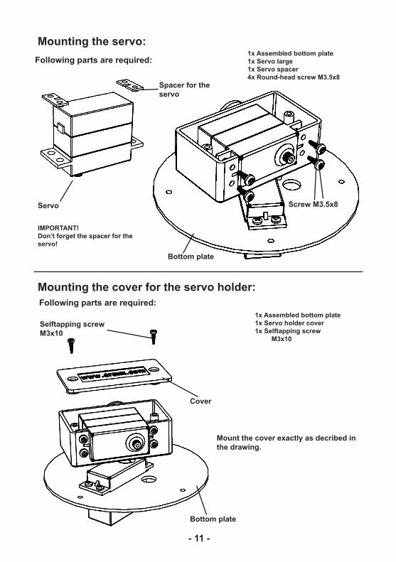
- 11 -
Mounting the servo:Following parts are required:
1x Assembled bottom plate1x Servo large1x Servo spacer4x Round-head screw M3.5x8
Mount the cover exactly as decribed in the drawing.
IMPORTANT!Don’t forget the spacer for the servo!
Servo
Selftapping screwM3x10
Bottom plate
Screw M3.5x8
Spacer for the servo
Mounting the cover for the servo holder:Following parts are required:
1x Assembled bottom plate1x Servo holder cover1x Selftapping screw M3x10
Cover
Bottom plate

- 12 -
Mounting the servo arm:Following parts are required:
1x Assembled bottom plate1x Servo arm1x Servo screw large M2.3x6
Servo arm
Servo screw M2.3x6 Bottom plate
Mount the servo arm exactly as described in the drawing!
Mounting the servo arm:Following parts are required:
1x Assembled bottom plate1x Servo coupling rod1x Servo screw small M2x62x Servo screw large M2.3x6
Mount the servo arm exactly as described in the drawing!
Bottom plate
Servo screw M2x6
Coupling rod
Servo screw M2.3x6
TEST!Can the rod rotate freely at 180 degrees?

- 13 -
Mounting the dual servo:
1x Dual servo holder2x Disc with axis2x Round-head screw M3 x 82x O-Ring M32x Locknut M3 4x Selftapping screw 2.6x6 1x Cover3x Selftapping screw 2.3x82x Servo disc2x Servo screw small M2x62x Servo DGServo 12g
For the final assembly of the dual servo, following parts are required:
Miniservo DGServo 12g
Selftapping screw 2.6x6
Cover for dual servo holder
Locknut M3
Disc with axis
Dual servo holder
Round-head screw M3 x 8
Servo disc
Selftapping screw 2.3x8
Dual servo holderwith servos
Dual servo holderwith servos Servo screw
M2x6
Mount the dual servo exactly and in the same order as described in the drawing!
O-Ring M3

- 14 -
Servo holderwrist
Selftapping screw 2.6x6
Mounting the dual servo holder:Following parts are required:
1x Assembled bottom plate1x Dual servo holder2x Servo screw small M2x62x Servo screw large M2.3x6
1x Miniservo DGServo 12g1x Servo holder wrist2x Selftapping screw M2.6x6
Mounting the wrist servo:Following parts are required:
Servo screw M2.3x6
Bottom plate
Miniservo DGServo 12g
Mount the wrist servo exactly as described in the drawing.
Mount the dual servo exactly as described in the drawing.
Servo screw M2x6
TEST!Can the dual servo rotate freely at 180 degrees?

- 15 -
Servo disc
Servo screw M2x6
Final assembly of the wrist servo:
1x Assembled wrist1x Servo disc1x Servo screw small M2x6
Following parts are required:
Assembled wrist
Mount the servo disc exactly as described in the drawing.

- 16 -
Mounting the finger servo holder:
Following parts are required:
Mount the finger servo holder exactly as described in the drawing.
Round-head screwM3x8
Finger servo holder
Locknut M3 Servo disc
Assembled wrist
Mounting the finger servo holder:Following parts are required:
1x Assembled wrist1x Finger servo holder1x Servo disc1x Screw M3x81x O-Ring M31x Locknut M3
Finger servo holder
Wrist assembly
Mount the servo disc exactly as described in the drawing.
Servo screw M2x6
1x Assembled wrist1x Finger servo holder2x Servo screw small M2x6
TEST!Can the wrist rotate freely at 180 degrees?
O-Ring M3

- 17 -
Fasten the servo at the servo holder exactly as described in the drawing
Mounting the finger servo:1x Assembled wrist1x Mini servo DGServo 12g2x Selftapping screw M2.6x6
Following parts are required:
Selftapping screw M2.6x6
Following parts are required:
Mini servo DGServo 12g
Mounting the finger servo holder:1x Assembled Wrist1x Servo disc1x Servo screw small M2x6
Servo screw M2x6
Assembledwrist
Fasten the disc on the servo exactly as described in the drawing

- 18 -
Fasten the wrist on the arm exactly as described in the drawing.
Mounting the finger:1x Assembled wrist1x Finger2x Servo screw small M2x62x Servo screw large M2.3x6
Following parts are required:
Mount the finger exactly as described in the drawing.
AssembledBottom plate
Assembledwrist
Finger
Servo screw M2x6
Final arm assembly:Following parts are required: 1x Assembled wrist
1x Assembled bottom plate2x Servo screw small M2x62x Servo screw large 2.3x6
Servo screw M2.3x6
Assembledwrist
Servo screw M2.3x6
Servo screw M2x6
TEST!Can the finger rotate FREELY?

- 19 -
Mounting the base and the PCB:1x Metal base4x Spacer M3x64x Spacer M3x30Following parts are required:
Metal base
Spacer M3x6
Base
Spacer M3x30

- 20 -
Final assembly of the Robot Arm :
Following parts are required:1x Base assembly1x ARM assembly4x Round-head screw M3x6
Round-head screw M3x6
There is no PCB included with the Robot Arm Chassis

- 21 -
READY !
There is no PCB included with the Robot Arm Chassis
Top Related