


Languages
Pages
Legal


1
D
S
GB
F
J. EberspächerGmbH & Co.Eberspächerstr. 24D - 73730 Esslingen
Telefon (zentral)(0711) 939 - 00Telefax(0711) 939 - 0500
www.eberspaecher.com
Eberspächer ®
Subject to change
Technical DescriptionOperating InstructionsInstallation Instructions
–Telephonic remote control for Eberspächerauxiliary heating
Extent of delivery:1 GSM module (stationary part)1 set of cables for heater1 set of cables for mini clock1 GSM windshield antenna
incl. cleaning cloth1 push-button1 tab connector housing, 6-pin1 push-on contact housing, 6-pin6 Junior timer contacts3 screws
A SIM card from a mobile phone network operatoris required to operate the CALLTRONIC.
The mobile phone is not included in the extentof delivery!
Order number – CALLTRONIC 12 V:22 1000 32 26 00
Additional components (Optional):Mini clockOrder No. 22 1000 31 31 00
2
D
S
GB
F
Contents Page
Operating instructions
Operating the CALLTRONIC .................................. 2
General operating information ............................... 2
Reset PIN .............................................................. 2
Operating modes ................................................... 3
Operating the heater via the numeric keyson the telephone ................................................... 3
Functionsa) Select heating / ventilation mode .................. 4b) Heating / ventilation running time .................. 4c) Special functions ............................................ 5
Fault correction ..................................................... 5
Contents / Operating Instructions
Operating the CALLTRONIC
The CALLTRONIC is an operating element, toremotely operate the heater with a DTMF telephoneor mobile phone via the GSM network from a dis-tance. You can select between the heating andventilation operating modes. The following settingtimes are available for the heating period: 10, 20,30, 40, 50, 60, 90 and 120 minutes.If preselected mode is required, a mini clock mustbe used instead of the push-button.
Hazard!• Pacemakers and hearing aids can be negatively
influenced.• The SIM card and the SIM cardholder can be
removed at any time – small children couldswallow them.
Please note!• When calling the CALLTRONIC, additional costs
are incurred due to the telephone charges.• The range depends on the network operator
(“radio hole” – transmission gaps).• It is important that the vehicle manufacturer’s
instructions and regulations for the installationand operation of a mobile phone or GSM moduleare observed and complied with.
• The CALLTRONIC can only be operated with anexternal GSM outdoor antenna in vehicles witha metalised windscreen.
General operating information
• The voice output has to be waited for before enter-ing the numeric key, otherwise the function of thekey will be ignored.
• The connection is terminated after 30 secondswithout input.
• Reset PIN:If you have forgotten your PIN number for settingup the connection to the CALLTRONIC, you canreset it as follows:11. Sit in the vehicle.12. Switch off the heater if it is switched on.13. Phone the CALLTRONIC using the telephone.14. Use the push-button or the mini clock to switch
the heater on following the voice output “EnterPIN“ within 30 seconds. At the end of the 30seconds, the heater must be switched on,otherwise the programme is aborted and theprocess has to be repeated.
15. Wait until the voice output “PIN invalid“.16. Voice output “Enter PIN“.17. Enter the PIN number “0000“.18. Voice output “Enter PIN“.19. Enter the PIN number “0000“ again.10. Voice output “PIN OK“.11. Voice output “Input function“.The PIN number “0000“ is now stored for startingthe device.You can change the PIN number at any time, asdescribed in the table on Page 5.
Page
Installation instructions
Installing the CALLTRONIC ................................. 6
Attaching the windscreen antenna ....................... 6
Insert SIM card ...................................................... 7
Installing the operating elements .......................... 7
Insert fuse and check function ............................. 7
Technical data ....................................................... 7
Circuit diagrams parts list ..................................... 8
Circuit diagrams at the end of these instructions

3
D
S
GB
F
Operating the heater via the numerickeys on the telephone
You first have to set up a connection between thetelephone and the CALLTRONIC.
To do this, dial the number assigned to you byyour network operator.
The CALLTRONIC signals the following text:
“Eberspächer heater – Input PIN“.
Now enter the 4-digit PIN No.(The PIN is set to 0000 in the works).
The following 3 operating modesare available
Note:If malfunctions occur in the heater during operation(e.g. due to a lack of fuel), these can be interro-gated after the malfunction has occurred usingFunction 6 (where the diagnosis cable is connected).The malfunction is corrected with the aid of theoperating instructions for the heater.
1. Stand-alone operation
The function keys 0 to 7 are active at the telephone(see the following table).The push-button installed can be used to switch theheater on or off. If the heater is switched on usingthe push-button, the heating function is activatedwith a duration of 40 mins. The push-button alsofunctions without a SIM card. The push-buttonflashes if an error occurs in the heater.
2. Combination with mini clock
The function keys 0 to 3 and 5 to 7 are active (seefollowing table).The functions of the function key 4 (Select operatingmode) are taken over by the mini clock (see installa-tion and operating instructions for the mini clock).When switching on the heater via the mini clock, theoperating mode last set with the mobile phone isalways activated. If a malfunction occurs in theheater, the reading in the mini clock display changesbetween the time and “--“.If the CALLTRONIC is connected with the mobilephone, “--“ appears in the mini-clock display.
3. Combination with mini controller
When combined with the CALLTRONIC, the minicontroller only serves to specify the set value.Select heating mode at the mini controller. The redLED in the mini controller only serves as an operat-ing display – not as an operating mode display – theoperating mode is selected via the remote control.
If the PIN No. is wrong, the following messageappears:
“PIN invalid“.
You now have the opportunity to enter the correctPIN No.
If the PIN No. is correct, the following messageappears:
“PIN OK – Input command“.
You can now enter your settings for the heater viathe CALLTRONIC.
The following table on Pages 4 and 5 shows whichfunctions are available to you.

4
D
S
GB
F
Functions
a) Select heating / ventilation operating mode
Numeric key Function Voice output
0 Switch off operating mode Heater off – Input command(heating / ventilation)
1 Activate heating mode • Heater on – duration... minutes – Input command• Heater on (only for mini clock) – Input command
2 Activate ventilation mode • Ventilation on – duration ... minutes – Input command• Ventilation on (only for mini clock) – Input command
3 Status check • Heater on – duration ... minutes – Input command• Heater on (only for mini clock) – Input command• Ventilation on – duration ... minutes – Input command• Ventilation on (only for mini clock) – Input command• Heater off – Input command
b) Heating / ventilation running time(If the mini clock is connected, the following function for numeric key 4 does not work)
Numeric key Function Voice output
4 Input duration • Input durationHeating and Ventilation • Input invalid – Input command
(Only if mini clock connected)
1 Select duration 10 mins. Duration 10 minutes – Input command
2 Select duration 20 mins. Duration 20 minutes – Input command
3 Select duration 30 mins. Duration 30 minutes – Input command
4 Select duration 40 mins. Duration 40 minutes – Input command
5 Select duration 50 mins. Duration 50 minutes – Input command
6 Select duration 60 mins. Duration 60 minutes – Input command
7 Select duration 90 mins. Duration 90 minutes – Input command
8 Select duration 120 mins. Duration 120 minutes – Input command
9 No function Input invalid – Input command
0 No function Input invalid – Input command

5
D
S
GB
F
c) Special functions
Numeric key Function Voice output
5 The following language is selected by pressing Key 5.Repeat the function until the required language is announced.
Language selected: Input command• German (in the selected language)• Swedish• English• French
The following function, numeric key 6, only applies for the trade appliances (retrofit) –diagnosis cable (blue / white) must be connected
6 Enquire heater condition • Heater OK – Input command(Diagnosis analysis) • Heater not OK – Input command
• Input invalid – Input command(if diagnosis cable not connected)
7 Change PIN Input new PIN
xxxx Enter new PIN Input new PIN
xxxx Enter new PIN • PIN OK – Input command(for confirmation) • Input invalid – Input command
8 No function Input invalid – Input command
9 No function Input invalid – Input command
Problem Possible cause Possible corrective measure
No connection No supply voltage Check fuse and wiring
to the CALLTRONIC Weak signal Change location of the vehicle; check antenna
Outside of the GSM supply area Check the supply range of the network operator
Network block set Check network blocks
Network overloaded Call again later
SIM card invalid Call using another phone network operator
SIM card incorrectly inserted Ensure that the SIM card has been correctlyinserted; the card holder must lock home
SIM card contacts soiled Clean the SIM card with a dry cloth
SIM card with wrong number Only SIM cards with 3 volts possibleof volts
SIM card damaged Carry out a visual check;give SIM card back to network operator
Fault correctionIf problems occur while you are using theCALLTRONIC, first try to find a solution in thefollowing list.
If the problem continues, please contact anEberspächer service workshop.

6
D
S
GB
F
Installing the CALLTRONIC
The CALLTRONIC is only installed in the inside of thevehicle in accordance with the installation drawing.Wherever possible, the installation position shouldnot be subjected to direct sunlight.
Attaching the windscreen antenna
The windscreen antenna is attached to the insideof the windscreen or rear window.
Assembly:Before sticking on the windscreen antenna �, therelevant position on the screen � should be cleanedusing the enclosed cloth and should be dry.Pull off the protective strip from the sticky tabs.Install the antenna cable to the CALLTRONIC � andconnect.
Note:Length of the antenna cable: 5 m.
Installation InstructionsPlease note!• The SIM card should be able to be replaced even
when installed.• Please ensure that you observe and comply with
the instructions and regulations of the vehiclemanufacturer with respect to the installation andoperation of a mobile phone or GSM module.
� CALLTRONIC� SIM cardholder� Push-button with LED
� Heater cable� Mini clock cable (optional)� GSM windscreen antenna

7
D
S
GB
F
Technical data
Working Voltage: 12 Volts
GSM Bands: Dual Band EGSM900GSM1800
GSM Class: Small MS
Transmit Power: Class 4 in EGSM900Class 1 in GSM1800
Operating Temperature: –20 °C to +50 °C
Storage Temperature: –30 °C to +85 °C
Dimensions: 140 x 100 x 36 mm
You must insert the SIM card before you can use theCALLTRONIC:� To release the lock on the SIM cardholder, press
the yellow button – the SIM cardholder springs outa bit.
� Pull out the SIM cardholder.� Insert SIM card with chip (contacts) facing
upwards.� Re-insert the SIM cardholder in the appliance,
until it locks into place.
Note:Only SIM cards without a PIN and with 3-volttechnology can be used.
Installation of the operating elements
Push-buttonFit the enclosed push-button in the view of the driver(Drill hole 10 mm, max. wall thickness 2.5 mm).Connect the cables in accordance with the circuitdiagram.
Mini-clock (Option)Install the mini clock (separate add-on) in accord-ance with the instructions supplied. Connect thecables in accordance with the circuit diagram.
Insert the SIM card
Insert the fuse and check the function
The operating element must be connected and fullyfunctioning before inserting the fuse.Insert the CALLTRONIC (5 A) fuse and check thefunction of the CALLTRONIC after approx. 30 sec-onds (time until the GSM module has signed on tothe network) with a telephone or mobile phone.
Please note!The heater diagnosis cable (blue / white) must beconnected for fault recognition (only for trade appli-ances – retrofit).The operating element must be connected and fullyfunctioning before inserting the fuse. The appliancedetects whether a push-button or a mini-clock isconnected when the voltage supply is applied forthe first time. The CALLTRONIC does not acceptsubsequent changes.

8
D
S
GB
F
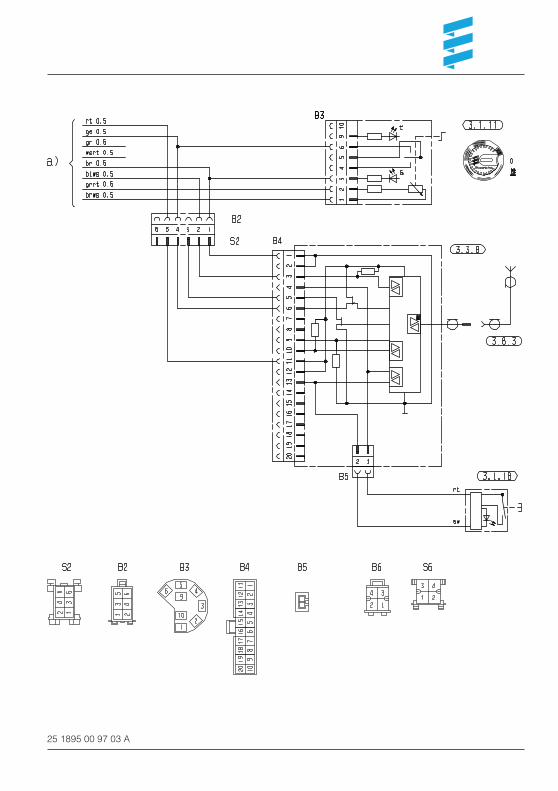
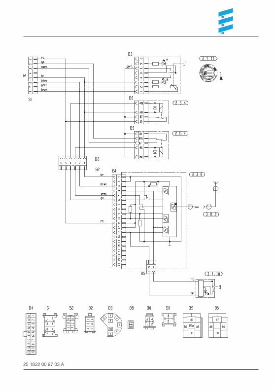
Please note!The CALLTRONIC must be connected in accord-ance with the circuit diagrams at the end of theseinstructions. Note the type of heater!
Circuit diagrams parts list
2.5.4 Switch on relay2.5.9 Ventilation relay
3.1.11 Round operating device3.1.17 AIRTRONIC mini controller3.1.18 CALLTRONIC push-button
3.2.12 Time switch mini 12 / 24 volts3.2.14 Time switch mini lighting (only 12 volts)
3.3.8 CALLTRONIC remote control
3.8.3 Antenna
a) Connecting the operating elements to the heater• rt Plus supply, terminal 30• ge Contact signal S+• gr Actual temperature value• ws rt Switch off theft warning system• br Minus supply, terminal 31• bl ws; bl Diagnosis• gr rt Set temperature value• br ws Sensor reference signal• sw ws Switch on ventilation
z) Terminal 58 (lighting)
Insulate any cable ends not used.
The connectors and socket housing are shown fromthe cable entry side.
Cable colours
sw = blackws = whitert = redge = yellowgn = greenvi = violetbr = browngr = greybl = blueli = lilac
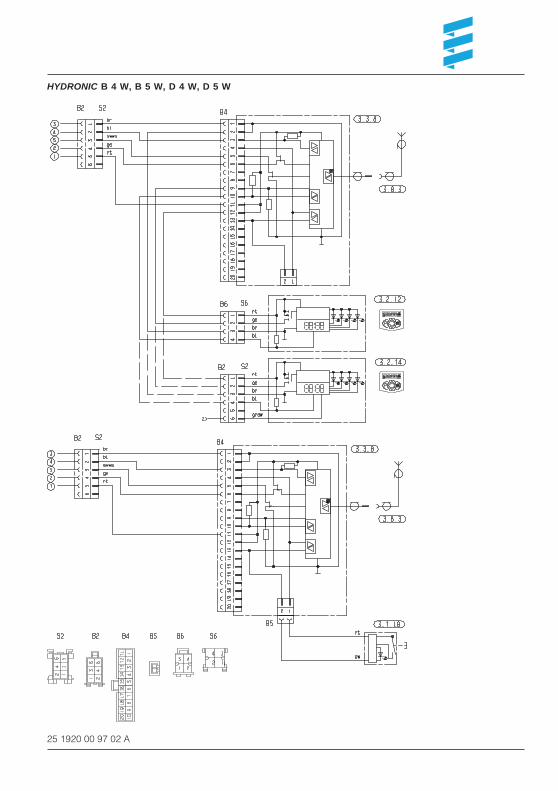
HYDRONIC B 4 W, B 5 W, D 4 W, D 5 W
25 1920 00 97 02 A

AIRTRONIC – 1
25 2069 00 97 04 A

25 2069 00 97 04 A

AIRTRONIC – 2
25 2069 00 97 05 A

25 2069 00 97 05 A

B 1 L P compact, B 1 L C compact, D 1 L P compact, D 1 L C compact,B 3 L P compact, B 3 L C compact, D 3 L P compact, D 3 L C compact
25 1895 00 97 03 A
25 1895 00 97 03 A

D 5 L C
25 1822 00 97 03 A
25 1822 00 97 03 A

D 8 L C
25 1766 00 96 02 A

25 1766 00 96 02 A

HYDRONIC 10
25 2044 00 96 03 A
Top Related