


Languages
Pages
Legal


Earthquake Resistant Design Philosophy and
Approach in New Zealand
Donald Kirkcaldie
Earthquake Resistant Design Philosophy and
Approach in New Zealand
Donald Kirkcaldie

2
The Development of Earthquake Resistant DesignThe Development of Earthquake Resistant Design
1931 Napier Earthquake – Design lateral loading of 0.1g introduced
1964 Anchorage and Niigata Earthquakes – major damage to infrastructure due to soil liquefaction
1971 San Fernando Earthquake in California:• Serious damage to major highway structures
• Provided the impetus for a concerted international research effort
• Led to the initiation of NZ’s seismic design philosophy and approach – MWD Highway Bridge Design Brief published, with updates in 1972, 1973, and 1978.

3
New Zealand’s SeismicityNew Zealand’s Seismicity
NZ’s seismicity
• Comparable to California, and areas adjacent to the Himalayan system, e.g. Burma, Bangladesh
• Major earthquakes in recent times have included:• 1855 Wairarapa - ~8.1 magnitude• Since 1885: • ~15 7.0 - 7.9 magnitude & 17 6.0 – 6.9 magnitude• I.e. > two major events every ~10 years
• Seismicity varies throughout the country as shown in the next slide

4
New Zealand Seismicity ZonationNew Zealand Seismicity Zonation
5
New Zealand’s Earthquake Resistance PhilosophyNew Zealand’s Earthquake Resistance Philosophy
Forces imposed on bridge piers can exceed 1g for the more rigid structures, scaling down to ~0.2 g for more flexible structures, if the bridges remain elastic.
Costly and seldom economically justifiable
Build energy absorbing capability into the structure and use this to reduce the earthquake forces to be resisted.
Energy absorption provided through ductile inelastic action, focused to occur only in members specifically detailed for the purpose.
6
Traditional Performance PrinciplesTraditional Performance Principles
(a) After a design return period event:• Damage may have occurred and temporary repairs may be required
• Bridge is to be useable by emergency traffic
• Bridge is to be able to be reinstated to full capacity for traffic and seismic loads
(b) After an event of return period significantly less than the design value:• Damage should be minor
• No disruption to traffic
(c) After an event of return period significantly greater than the design value• The bridge should not collapse
• The bridge should be useable by emergency traffic after temporary repair
• Repair should be feasible, albeit to a lower level of load capacity

7
Traditional Performance PrinciplesTraditional Performance Principles
The design earthquake adopted intensity is a function of the importance and design life of the structure.
A bridge is categorised for its structural action under horizontal seismic load.
Maximum ductility factors are assigned based on the manner in which and extent to which plastic mechanisms can form and their accessibility for repair. (See next slide)

8
Categorisation of Structures – Maximum Ductility Factor µCategorisation of Structures – Maximum Ductility Factor µ

9
Traditional Performance PrinciplesTraditional Performance Principles
In practice, design is only carried out for (a)
Bridges well designed for (a) are expected to also satisfy (c) due to:
• Greater actual member strength
• Greater damping due to more of the response being inelastic
• Reduced structural stiffness due to softening of the structure
• Greater structure displacement ductility capability

10
Updated Required Bridge Performance LevelsUpdated Required Bridge Performance Levels
NZTA Bridge Manual has traditionally aligned with the NZ Loading Code
NZS 1170.5:2006 has introduced explicit consideration of SLS requirements in addition to the ULS.
Corresponding draft amendments have been prepared for the Bridge Manual as follows:
11
Draft Revised Bridge Performamce RequirementsDraft Revised Bridge Performamce Requirements
SLS1 (100 year return period*)
• No damage to structural or non-structural components
SLS2 (500 year return period*)
• No more than minor damage to primary structural members• Damage to secondary or non-structural components shall not
significantly impede the operational functionality of the bridge
ULS (2500 year return period*)
• Structural stability is maintained• Access available for emergency vehicles after temporary repairs• Damage may be extensive, but structure should be repairable to
full capacity
* Return periods are those applying to most state highway bridges

12
Implementation - OverviewImplementation - Overview
Earthquake resistant design is more an art than a science
• The designer needs to develop an understanding of the likely structural behaviour
• Choices may be necessary in order to optimise the structural form
• Analysis is only a guide to likely behaviour, not an accurate representation. Some significant assumptions are involved
• Robust detailing is required to cater for the unexpected and the possibility of larger than design events

13
Implementation – Site AssessmentImplementation – Site Assessment
Site assessment
• Categorisation of the site subsoil
• Proximity of active faults
• Need for a site specific hazard study (- active fault proximity, bridge of high value)
• Development of site hazard spectra
• Selection of appropriate earthquake records if time-history analysis is to be undertaken
• Site stability (- mass ground movement, potential for soil liquefaction)

14
Implementation – Choice of Structural FormImplementation – Choice of Structural Form
Considerations in the choice of structural form include:• Bridge form (simply supported v continuous
superstructure, support on bearings v build superstructure integral with substructure, etc.)
• Materials to be used, the structure’s flexibility, and ductility attainable with a particular configuration
• The number and location of supports used to resist seismic forces, and relative distribution of mass and stiffness within the structure
• The balance between displacement and strength requirements. • Flexibility decrease the seismic response accelerations but
increases the movement at joints, and their cost.

15
Implementation – Choice of Structural Form (contd.)Implementation – Choice of Structural Form (contd.)
Considerations in the choice of structural form include (contd.):
• The number, location and form of energy dissipation points. • Are they to be plastic hinges in structural members or energy
dissipation devices, and their accessibility for repair.
• The number location and function of movement joints
• Maintenance of structural integrity and prevention of collapse of spans off supports
• The bridge response to EQ in all directions

16
Implementation - AnalysisImplementation - Analysis
Selection of the analysis method should take into account:• The complexity of the structural form
• The nature of the anticipated response to ground motions
• The degree of inelastic behaviour
Three forms of analysis are available:• Equivalent static force analysis
• Elastic modal spectral analysis
• Inelastic dynamic analysis by numerical integration
Analytical results only provide an indication of a structure’s likely behaviour. The structure must be capable of surviving deformations exceeding what analysis might predict

17
Implementation – Capacity DesignImplementation – Capacity Design
Capacity Design entails the following:
• The predetermination of locations in the structure at which plastic yielding will be designed to occur.
• The design of those plastically yielding locations for yielding to initiate at an acceptable intensity of earthquake ground motion
• The detailing of those plastically yielding locations to maintain their ability to yield in a controlled ductile manner throughout the response
• Other structural elements, intended not to yield, are detailed with sufficient reserve strength to remain elastic and so as to maintain their integrity

18
Implementation - DetailingImplementation - Detailing
Appropriate and robust detailing is required to ensure:
• That energy dissipation throughout the yielding of elements can occur
• The integrity of the structure will be maintained during response to earthquakes of greater than design intensity and to effects not predicted by the analysis
• In particular, that the collapse of spans is avoided
• No significant damage or loss of serviceability is incurred during earthquakes of SLS design intensity.

19
Implementation - DetailingImplementation - Detailing
Some critical areas of detailing to note include:
• Plastic hinge zones:• No lapping of primary flexural reinforcement in these zones• Increased confinement to prevent bar buckling• Increased shear reinforcement, due to reduced contribution
from the concrete
• Design of Non –Yielding Elements • These must withstand the forces induced by yielding elements
developing their “overstrength” capacity
• Prevention of span collapses• Linkage of spans to supports and to each other• Adequate overlap of girders with supports

20
Implementation – Detailing (contd.)Implementation – Detailing (contd.)
Some critical areas of detailing to note include (contd.):
• Freedom to Displace• The structure must have the freedom to displace to develop
the design ductility• Knock-off elements at the abutments and maybe elsewhere,
(unless designed as locked-in or with integral abutments)
• Deck Joints and Bearings• Ability to accommodate the SLS seismic movements• Security of bearings against being displaced

21
Detailing ExamplesDetailing Examples
Plastic hinge accessible for inspection
Resisting elements designed for PH overstrength
Reinforcement laps positions
Column & pile confinement
Joint shear reinforcement
Bar terminations
Pier top rotational inertia effects
22
Detailing ExamplesDetailing Examples
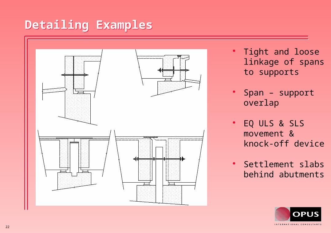
Tight and loose linkage of spans to supports
Span – support overlap
EQ ULS & SLS movement & knock-off device
Settlement slabs behind abutments

23
Detailing ExamplesDetailing Examples
Linkage to a pier
Deck slab diaphragm action

24
Base Isolation with Mechanical Energy DissipationBase Isolation with Mechanical Energy Dissipation
Base isolation with mechanical energy dissipation is a special case of the ductile capacity design approach
• The bridge superstructure is isolated from the worst effects of the ground motion by means of flexible mounting, usually elastomeric bearings.
• The effect is to increase the period of response of the structure into a period range of the response spectrum where the earthquake shaking is less intense
• Increased equivalent structural damping is achieved through the use of special devices which rely on the cyclic yielding of steel or lead components

25
Base Isolation with Mechanical Energy DissipationBase Isolation with Mechanical Energy Dissipation

26
Base Isolation with Mechanical Energy DissipationBase Isolation with Mechanical Energy Dissipation
Base isolation with mechanical energy dissipation has been found to be most effective in situations where:
• The seismicity is high
• The substructures are stiff or are required to remain elastic
Note however, that foundation flexibility increases the section ductility demand on any form of plastically yielding element

27
Base Isolation with Mechanical Energy DissipationBase Isolation with Mechanical Energy Dissipation
Potential advantages of base isolation with mechanical energy dissipation lie in:• Reduced displacements compared to structures with elastomeric
bearings only – enabling simpler deck joint details
• Favourable reduction in the level of seismic forces imposed on the structure
• Redistribution of seismic forces on the substructure and foundations
• Enabling the use of non-yielding structural forms or components intended to remain elastic in the substructure
• Greater control over earthquake induced damage – Under design intensity earthquakes structural damage should be completely avoided.

28
ConclusionConclusion
Earthquake resistant design is not an exact science. Skilled judgement based on experience is a vital ingredient
Experience has shown that by using the ductile capacity design approach, bridges can be economically constructed to resist severe earthquakes
The philosophy and approach is equally applicable to areas of significant but lesser seismicity than NZ
In any area of potential seismic activity, it is essential lifeline bridges be of appropriate form, well tied together longitudinally, and detailed to ensure tolerance to seismic overload and unexpected effects
Top Related