


Languages
Pages
Legal

DUNE Timing System
Interface to Accelerator timing
Ideas for Near Detector
David Cussans
Upstream DAQ Meeting
16/03/2021

Introduction• Need knowledge of accelerator (beam spill) timing
– Need to know when neutrinos passing through far detector
– Near detector probably needs this information as well.
• FNAL provides accelerator timing information as signals on coax cables.
– See https://doi.org/10.1016/0168-9002(86)90569-3 , pages under https://www-bd.fnal.gov/controls/
– RFCLK (TCLK - 10MBit/s , Manchester encoded), BSYNC used by NoVA
– High quality timing information not available time-stamped w.r.t. GPS time/TAI. Lower precision information available from ACNET system
• Each experiment needs to make their own high precision measurement of accelerator timing
– Separate systems for
● Minos
● NoVA - See, e.g. https://dx.doi.org/10.1088/1742-6596/396/1/012034
• Use Far Detector GPS Interface Module hardware to time-stamp accelerator signals
- GIB has inputs for external signals
- Use of GIB would also allow timing signals to be propagated to Near Detector
15/3/20212 UDAQ meeting | David Cussans

21/7/2020 Timing System FDR | David Cussans3
Far DetectorOverall Timing System

Accelerator Interface
15/3/20214 UDAQ meeting | David Cussans
• Derive master timestamp/clock from GPS
– 62.5MHz clock derived from 10MHz from GPS disciplined oscillator.
– GPS time/TAI from GPS receiver
• Time-stamp signals from accelerator w.r.t. master clock
– edges of accelerator clock/data stream (TCLK)
– edges of accelerator messages (BSYNC)
– Measure evolution of phase w.r.t. master clock
● (Won’t read out 10M time-stamps/second)
• Decode accelerator messages

Near Detector
• Proposal to use same hardware for Near Detector
• Distribute clock and timestamps
– (What clock frequency? 62.5MHz same as FD? Doesn’t have to be )
• Distribute fixed (and low) latency messages from accelerator to ND on same fibre as clock/time-stamps.
• Need to have interface to accelerator for far detector timing. Use same hardware to also transmit timing to ND
• Single mode fibre / 1000Base-BX allows transmission of up to 80km between GPS system and ND
• Assume reliability is important, but cold/warm-swap capability not needed.
– Assuming that easier to get access for repair at ND than at FD
15/3/20215 UDAQ meeting | David Cussans

Near Detector timing - straw person
15/3/20216 UDAQ meeting | David Cussans
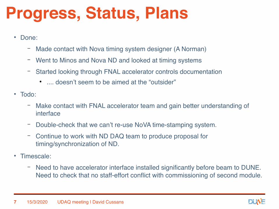
Progress, Status, Plans
• Done:
– Made contact with Nova timing system designer (A Norman)
– Went to Minos and Nova ND and looked at timing systems
– Started looking through FNAL accelerator controls documentation
● .... doesn’t seem to be aimed at the “outsider”
• Todo:
– Make contact with FNAL accelerator team and gain better understanding of interface
– Double-check that we can’t re-use NoVA time-stamping system.
– Continue to work with ND DAQ team to produce proposal for timing/synchronization of ND.
• Timescale:
– Need to have accelerator interface installed significantly before beam to DUNE. Need to check that no staff-effort conflict with commissioning of second module.
15/3/20207 UDAQ meeting | David Cussans

Summary
• Need an interface to accelerator timing signals
– Time-stamp beam spill information with GPS time for FD
• Proposing to use the same hardware design as for FD GPS interface (GIB)
• Investigating possibility of using “Single Phase Timing System” for Near Detector
– Provide clock and syncronization and low latency messages carrying accelerator information
15/3/20218 UDAQ meeting | David Cussans

Backup Slides:
A reminder of FD timing system

21/7/2020 Timing System FDR | David Cussans10
Far DetectorOverall Timing System

21/7/2020 Timing System FDR | David Cussans11
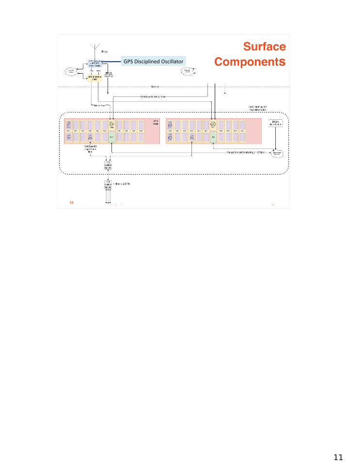
Surface
ComponentsGPS Disciplined Oscillator

21/7/2020 Timing System FDR | David Cussans12
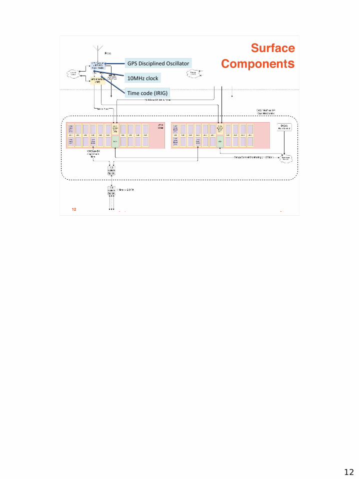
Surface
ComponentsGPS Disciplined Oscillator
10MHz clock
Time code (IRIG)

21/7/2020 Timing System FDR | David Cussans13
Surface
ComponentsGPS Disciplined Oscillator
GPS Interface (GIB)

21/7/2020 Timing System FDR | David Cussans14
Surface
ComponentsGPS Interface (GIB)
Clock/data to redundant systems in cavern

Protocol & Transport Mechanism• Clock and timing data encoded onto serial stream
• Transport over optical fibre
- 1000Base-BX (Bidirectional, on single SM fibre)
• 8b/10b encoded data (DC balance)
• 312.5MBit/s (slow enough for general purpose FPGA I/O)
- Used to generate 62.5MHz clock at endpoint
• Locked to 125MHz clock in DP cavern(s)
21/7/2020 Timing System FDR | David Cussans15

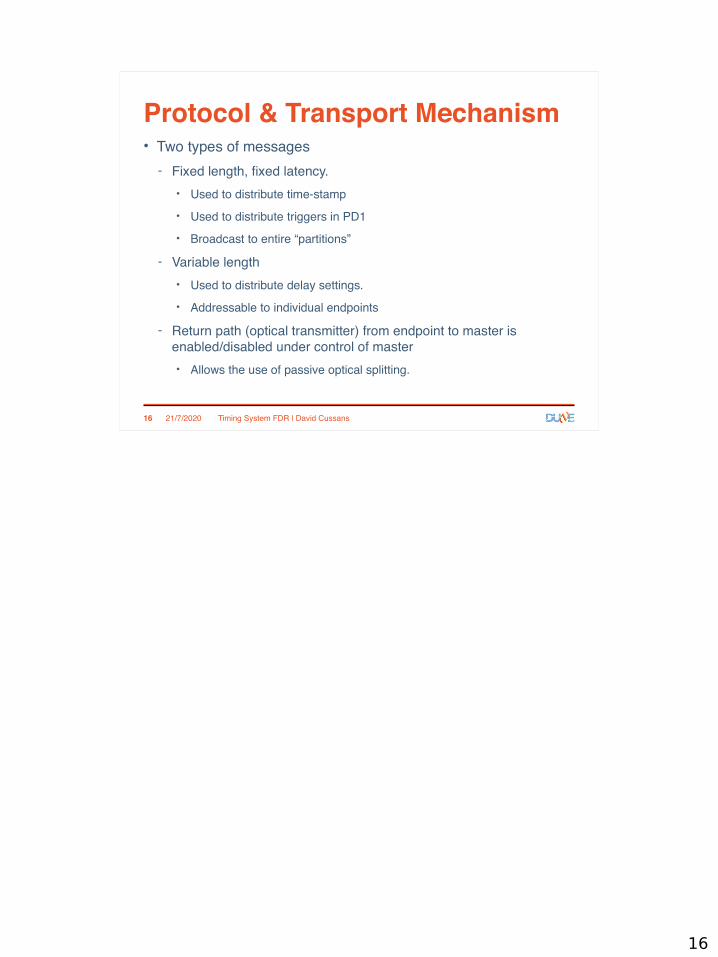
Protocol & Transport Mechanism• Two types of messages
- Fixed length, fixed latency.
• Used to distribute time-stamp
• Used to distribute triggers in PD1
• Broadcast to entire “partitions”
- Variable length
• Used to distribute delay settings.
• Addressable to individual endpoints
- Return path (optical transmitter) from endpoint to master is enabled/disabled under control of master
• Allows the use of passive optical splitting.
21/7/2020 Timing System FDR | David Cussans16

Protocol & Transport Mechanism• Bi-directional link allows round trip delay measurement
- Master Endpoint Master
- Adjust delay to bring all endpoints into alignment
• Endpoint maintains a 64-bit timestamp
- Aligned to UTC at initialization
- Increments with recovered clock
- Checked against master every ~ 100ms
• Protocol and endpoint interface described in https://edms.cern.ch/document/2395364/1
21/7/2020 Timing System FDR | David Cussans17
21/7/2020 Timing System FDR | David Cussans18
MicroTCA Crate
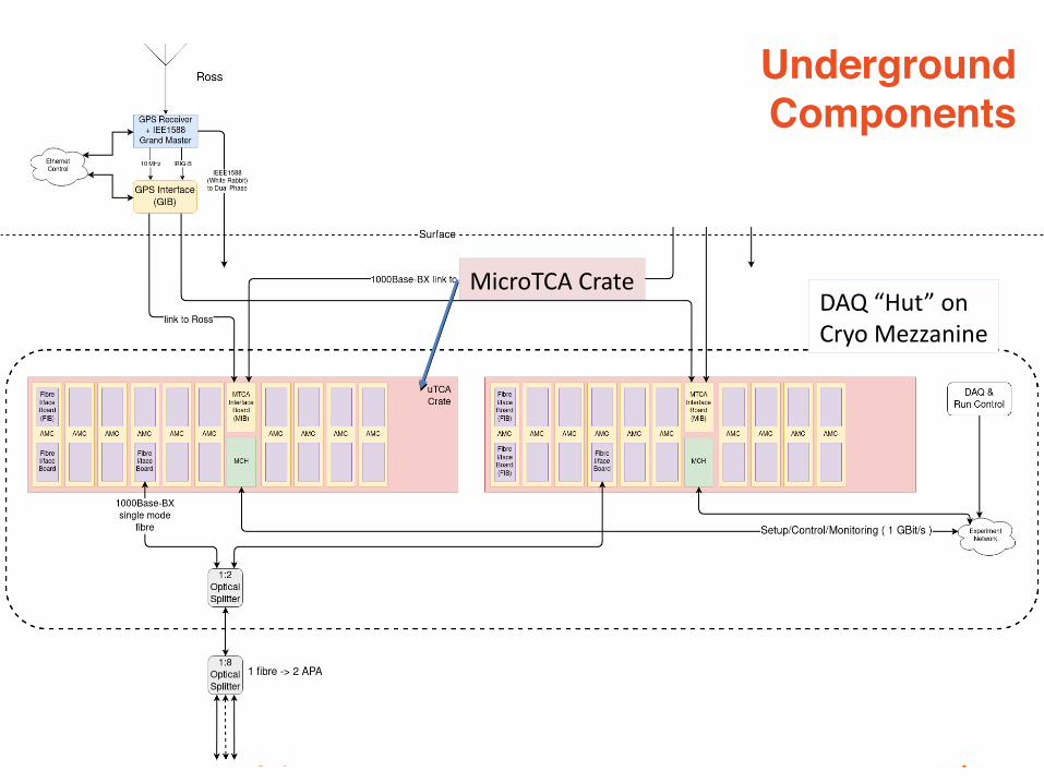
UndergroundComponents
DAQ “Hut” onCryo Mezzanine

21/7/2020 Timing System FDR | David Cussans19
MicroTCA Crate
MicroTCA Interface (MIB)
UndergroundComponents
DAQ “Hut” onCryo Mezzanine

21/7/2020 Timing System FDR | David Cussans20
UndergroundComponents
MicroTCA CrateMicroTCA Interface (MIB)
FMC carrier AMC (AFC)

21/7/2020 Timing System FDR | David Cussans21
UndergroundComponents
MicroTCA CrateMicroTCA Interface (MIB)
FMC carrier AMC (AFC)
Fibre Interface (FIB)

21/7/2020 Timing System FDR | David Cussans22
UndergroundComponents
Fibre Interface (FIB)
1000Base-BX SFP

21/7/2020 Timing System FDR | David Cussans23
UndergroundComponents
1:2 Optical Combiner/Splitter
1000Base-BX SFP
1:4 Optical Combiner/Splitter
• ”Hot Swap” between crates using 2:1 splitter
• Multiple endpoints from single fibre with 1:4 splitter

Components• GPS Disciplined Oscillator
- 10MHz clock
- Timecode (IRIG)
- Also has IEEE-1588 output (White Rabbit)
- Using Spectracom SecureSync for tests
21/7/2020 Timing System FDR | David Cussans24

Components
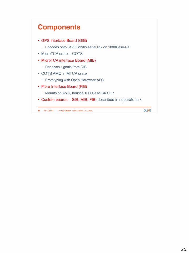
• GPS Interface Board (GIB)
- Encodes onto 312.5 Mbit/s serial link on 1000Base-BX
• MicroTCA crate – COTS
• MicroTCA interface Board (MIB)
- Receives signals from GIB
• COTS AMC in MTCA crate
- Prototyping with Open Hardware AFC
• Fibre Interface Board (FIB)
- Mounts on AMC, houses 1000Base-BX SFP
• Custom boards – GIB, MIB, FIB, described in separate talk
21/7/2020 Timing System FDR | David Cussans25

21/7/2020 Timing System FDR | David Cussans
• Requirement for v. high uptime -->
• GPS at top of each shaft
• Hot-swap crates• Can swap individual
fibres• Cross check two
systems for reliability
26
Uptime,Reliability
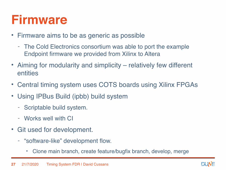
Firmware• Firmware aims to be as generic as possible
- The Cold Electronics consortium was able to port the example Endpoint firmware we provided from Xilinx to Altera
• Aiming for modularity and simplicity – relatively few different entities
• Central timing system uses COTS boards using Xilinx FPGAs
• Using IPBus Build (ipbb) build system
- Scriptable build system.
- Works well with CI
• Git used for development.
- “software-like” development flow.
• Clone main branch, create feature/bugfix branch, develop, merge
21/7/2020 Timing System FDR | David Cussans27

Firmware• Simulation test benches exist for main functions.
- Some have simulated Ethernet Interface – allows use of same software as real hardware
• Many features tested in ProtoDUNE1
- Which features tested, which will be tested described in separate talks.
• Overview of firmware at https://edms.cern.ch/document/2395358/1
• Repository at https://gitlab.cern.ch/protoDUNE-SP-DAQ/timing-board-firmware
21/7/2020 Timing System FDR | David Cussans28

Software• Set of interfaces (services) that are used by central configuration, control, monitoring
- Interface library (API) used by services
• Testing and commissioning with Python based scripts
- Calling underlying APIs to hardware
• Communication with FPGAs using IPBus
- UDP/IP based.
- Small footprint – no soft-core CPU
- Developed by CMS.
- Widely used in HEP.
• Timing system integrated with ArtDAQ for PD1
- New framework for PD2
• See other talks for ProtoDUNE-1 experience, future development and test plans
• Software framework described in EDMS https://edms.cern.ch/document/2395368/1
21/7/2020 Timing System FDR | David Cussans29

Summary• The Timing system for the Single-Phase DUNE Detectors will deliver a
clock and time stamps to all “endpoints” in caverns.
• Designed for high level of reliability (cross check between two GPS masters)
• Designed for high level of availability (swap between hardware using passive optical splitting)
• Only small number of different custom boards
- See separate talk
- Based on COTS FPGA boards with existing firmware support
• Core functionality demonstrated at ProtoDUNE-1
- See separate talk
• More details of development and testing plan in separate talk
• Project schedule and installation described in separate talk
21/7/2020 Timing System FDR | David Cussans30

BACKUP SLIDES

Why Not White Rabbit?• ProtoDUNE-SP initially had a triggered triggered readout
- Needed way of distributing messages with fixed latency
• Not provided by IEEE-1588 ( could extra functionality onto the same Ethernet link, but would be tricky)
• Wanted have endpoints as simple as possible
- DUNE-SP timing system has much simpler firmware
• Current WR implementations need a soft-core CPU in FPGA
• (c.f. relatively small state machine in endpoint block)
• Designed for passive optical splitting – allows redundant masters.
- Simple redundancy of master difficult for WR
• Do not see a reason for moving away from a system that has worked at ProtoDUNE
21/7/2020 Timing System FDR | David Cussans32

Optical Power BudgetdB / dBm
1:2 splitter loss (max) 4.40
See https://img-en.fs.com/file/datasheet/blockless-plc-splitters-datasheet.pdf
1:8 splitter loss (max) 10.60see https://www.fs.com/uk/products/11959.html
fibre attenuation ( 1db/km) 0.30https://www.thefoa.org/tech/loss-est.htm
1000Base-BX-20 Tx power (min) -9.00https://www.fs.com/au/products/75335.html1000Base-BX-20 Rx power (max) -23.00
power budget = Tx – Rx – losses (1000Base-BX-20) -1.30
1000Base-BX-80 Tx power (min) -2.00https://www.fs.com/uk/products/75352.html
1000Base-BX-80 Rx power (max) -24.00power budget = Tx – Rx – losses (1000Base-BX-80) 6.70
1000Base-BX-120 Tx power (min) -1.00https://www.fs.com/uk/products/75356.html
1000Base-BX-120 Rx power (max) -31.00power budget = Tx – Rx – losses (1000Base-BX-120) 14.70
21/7/2020 Timing System FDR | David Cussans33
Need 80km 1000Base-Bx SFPs

Test MTCA Crate in Bristol
21/7/2020 Timing System FDR | David Cussans34
MicroTCA Chassis
Power module110/240V inputHot-swap
Test timing endpoints
Hot swap fansFront-back airflow
MCH (interface to crateIPBus on Ethernet)
Passive opticalSplitter
COTS AMC withCustom FMC (FIB)
DUNE Timing System
Interface to Accelerator timing
Ideas for Near Detector
David Cussans
Upstream DAQ Meeting
16/03/2021

Introduction• Need knowledge of accelerator (beam spill) timing
– Need to know when neutrinos passing through far detector
– Near detector probably needs this information as well.
• FNAL provides accelerator timing information as signals on coax cables.
– See https://doi.org/10.1016/0168-9002(86)90569-3 , pages under https://www-bd.fnal.gov/controls/
– RFCLK (TCLK - 10MBit/s , Manchester encoded), BSYNC used by NoVA
– High quality timing information not available time-stamped w.r.t. GPS time/TAI. Lower precision information available from ACNET system
• Each experiment needs to make their own high precision measurement of accelerator timing
– Separate systems for
● Minos
● NoVA - See, e.g. https://dx.doi.org/10.1088/1742-6596/396/1/012034
• Use Far Detector GPS Interface Module hardware to time-stamp accelerator signals
- GIB has inputs for external signals
- Use of GIB would also allow timing signals to be propagated to Near Detector
15/3/20212 UDAQ meeting | David Cussans
2

21/7/2020 Timing System FDR | David Cussans3
Far DetectorOverall Timing System
3

Accelerator Interface
15/3/20214 UDAQ meeting | David Cussans
• Derive master timestamp/clock from GPS
– 62.5MHz clock derived from 10MHz from GPS disciplined oscillator.
– GPS time/TAI from GPS receiver
• Time-stamp signals from accelerator w.r.t. master clock
– edges of accelerator clock/data stream (TCLK)
– edges of accelerator messages (BSYNC)
– Measure evolution of phase w.r.t. master clock
● (Won’t read out 10M time-stamps/second)
• Decode accelerator messages
4

Near Detector
• Proposal to use same hardware for Near Detector
• Distribute clock and timestamps
– (What clock frequency? 62.5MHz same as FD? Doesn’t have to be )
• Distribute fixed (and low) latency messages from accelerator to ND on same fibre as clock/time-stamps.
• Need to have interface to accelerator for far detector timing. Use same hardware to also transmit timing to ND
• Single mode fibre / 1000Base-BX allows transmission of up to 80km between GPS system and ND
• Assume reliability is important, but cold/warm-swap capability not needed.
– Assuming that easier to get access for repair at ND than at FD
15/3/20215 UDAQ meeting | David Cussans
5

Near Detector timing - straw person
15/3/20216 UDAQ meeting | David Cussans
6
Progress, Status, Plans
• Done:
– Made contact with Nova timing system designer (A Norman)
– Went to Minos and Nova ND and looked at timing systems
– Started looking through FNAL accelerator controls documentation
● .... doesn’t seem to be aimed at the “outsider”
• Todo:
– Make contact with FNAL accelerator team and gain better understanding of interface
– Double-check that we can’t re-use NoVA time-stamping system.
– Continue to work with ND DAQ team to produce proposal for timing/synchronization of ND.
• Timescale:
– Need to have accelerator interface installed significantly before beam to DUNE. Need to check that no staff-effort conflict with commissioning of second module.
15/3/20207 UDAQ meeting | David Cussans
7

Summary
• Need an interface to accelerator timing signals
– Time-stamp beam spill information with GPS time for FD
• Proposing to use the same hardware design as for FD GPS interface (GIB)
• Investigating possibility of using “Single Phase Timing System” for Near Detector
– Provide clock and syncronization and low latency messages carrying accelerator information
15/3/20218 UDAQ meeting | David Cussans
8

Backup Slides:
A reminder of FD timing system

21/7/2020 Timing System FDR | David Cussans10
Far DetectorOverall Timing System
10
21/7/2020 Timing System FDR | David Cussans11
Surface
ComponentsGPS Disciplined Oscillator
11
21/7/2020 Timing System FDR | David Cussans12
Surface
ComponentsGPS Disciplined Oscillator
10MHz clock
Time code (IRIG)
12

21/7/2020 Timing System FDR | David Cussans13
Surface
ComponentsGPS Disciplined Oscillator
GPS Interface (GIB)
13

21/7/2020 Timing System FDR | David Cussans14
Surface
ComponentsGPS Interface (GIB)
Clock/data to redundant systems in cavern
14

Protocol & Transport Mechanism• Clock and timing data encoded onto serial stream
• Transport over optical fibre
- 1000Base-BX (Bidirectional, on single SM fibre)
• 8b/10b encoded data (DC balance)
• 312.5MBit/s (slow enough for general purpose FPGA I/O)
- Used to generate 62.5MHz clock at endpoint
• Locked to 125MHz clock in DP cavern(s)
21/7/2020 Timing System FDR | David Cussans15
15
Protocol & Transport Mechanism• Two types of messages
- Fixed length, fixed latency.
• Used to distribute time-stamp
• Used to distribute triggers in PD1
• Broadcast to entire “partitions”
- Variable length
• Used to distribute delay settings.
• Addressable to individual endpoints
- Return path (optical transmitter) from endpoint to master is enabled/disabled under control of master
• Allows the use of passive optical splitting.
21/7/2020 Timing System FDR | David Cussans16
16

Protocol & Transport Mechanism• Bi-directional link allows round trip delay measurement
- Master Endpoint Master
- Adjust delay to bring all endpoints into alignment
• Endpoint maintains a 64-bit timestamp
- Aligned to UTC at initialization
- Increments with recovered clock
- Checked against master every ~ 100ms
• Protocol and endpoint interface described in https://edms.cern.ch/document/2395364/1
21/7/2020 Timing System FDR | David Cussans17
17

21/7/2020 Timing System FDR | David Cussans18
MicroTCA Crate
UndergroundComponents
DAQ “Hut” onCryo Mezzanine
18

21/7/2020 Timing System FDR | David Cussans19
MicroTCA Crate
MicroTCA Interface (MIB)
UndergroundComponents
DAQ “Hut” onCryo Mezzanine
19

21/7/2020 Timing System FDR | David Cussans20
UndergroundComponents
MicroTCA CrateMicroTCA Interface (MIB)
FMC carrier AMC (AFC)
20

21/7/2020 Timing System FDR | David Cussans21
UndergroundComponents
MicroTCA CrateMicroTCA Interface (MIB)
FMC carrier AMC (AFC)
Fibre Interface (FIB)
21

21/7/2020 Timing System FDR | David Cussans22
UndergroundComponents
Fibre Interface (FIB)
1000Base-BX SFP
22

21/7/2020 Timing System FDR | David Cussans23
UndergroundComponents
1:2 Optical Combiner/Splitter
1000Base-BX SFP
1:4 Optical Combiner/Splitter
• ”Hot Swap” between crates using 2:1 splitter
• Multiple endpoints from single fibre with 1:4 splitter
23

Components• GPS Disciplined Oscillator
- 10MHz clock
- Timecode (IRIG)
- Also has IEEE-1588 output (White Rabbit)
- Using Spectracom SecureSync for tests
21/7/2020 Timing System FDR | David Cussans24
24
Components
• GPS Interface Board (GIB)
- Encodes onto 312.5 Mbit/s serial link on 1000Base-BX
• MicroTCA crate – COTS
• MicroTCA interface Board (MIB)
- Receives signals from GIB
• COTS AMC in MTCA crate
- Prototyping with Open Hardware AFC
• Fibre Interface Board (FIB)
- Mounts on AMC, houses 1000Base-BX SFP
• Custom boards – GIB, MIB, FIB, described in separate talk
21/7/2020 Timing System FDR | David Cussans25
25

21/7/2020 Timing System FDR | David Cussans
• Requirement for v. high uptime -->
• GPS at top of each shaft
• Hot-swap crates• Can swap individual
fibres• Cross check two
systems for reliability
26
Uptime,Reliability
26

Firmware• Firmware aims to be as generic as possible
- The Cold Electronics consortium was able to port the example Endpoint firmware we provided from Xilinx to Altera
• Aiming for modularity and simplicity – relatively few different entities
• Central timing system uses COTS boards using Xilinx FPGAs
• Using IPBus Build (ipbb) build system
- Scriptable build system.
- Works well with CI
• Git used for development.
- “software-like” development flow.
• Clone main branch, create feature/bugfix branch, develop, merge
21/7/2020 Timing System FDR | David Cussans27
Three boards use same firmware blocksBlocks already developed for PD-1Good f/ware development environmentDave N. will answer details if asked to. (As
original f/ware architect).Development methodology known to work for
large, distributed teams (CMS, DUNE trigger primitives)
27

Firmware• Simulation test benches exist for main functions.
- Some have simulated Ethernet Interface – allows use of same software as real hardware
• Many features tested in ProtoDUNE1
- Which features tested, which will be tested described in separate talks.
• Overview of firmware at https://edms.cern.ch/document/2395358/1
• Repository at https://gitlab.cern.ch/protoDUNE-SP-DAQ/timing-board-firmware
21/7/2020 Timing System FDR | David Cussans28
28

Software• Set of interfaces (services) that are used by central configuration, control, monitoring
- Interface library (API) used by services
• Testing and commissioning with Python based scripts
- Calling underlying APIs to hardware
• Communication with FPGAs using IPBus
- UDP/IP based.
- Small footprint – no soft-core CPU
- Developed by CMS.
- Widely used in HEP.
• Timing system integrated with ArtDAQ for PD1
- New framework for PD2
• See other talks for ProtoDUNE-1 experience, future development and test plans
• Software framework described in EDMS https://edms.cern.ch/document/2395368/1
21/7/2020 Timing System FDR | David Cussans29
29

Summary• The Timing system for the Single-Phase DUNE Detectors will deliver a
clock and time stamps to all “endpoints” in caverns.
• Designed for high level of reliability (cross check between two GPS masters)
• Designed for high level of availability (swap between hardware using passive optical splitting)
• Only small number of different custom boards
- See separate talk
- Based on COTS FPGA boards with existing firmware support
• Core functionality demonstrated at ProtoDUNE-1
- See separate talk
• More details of development and testing plan in separate talk
• Project schedule and installation described in separate talk
21/7/2020 Timing System FDR | David Cussans30
30

BACKUP SLIDES
31

Why Not White Rabbit?• ProtoDUNE-SP initially had a triggered triggered readout
- Needed way of distributing messages with fixed latency
• Not provided by IEEE-1588 ( could extra functionality onto the same Ethernet link, but would be tricky)
• Wanted have endpoints as simple as possible
- DUNE-SP timing system has much simpler firmware
• Current WR implementations need a soft-core CPU in FPGA
• (c.f. relatively small state machine in endpoint block)
• Designed for passive optical splitting – allows redundant masters.
- Simple redundancy of master difficult for WR
• Do not see a reason for moving away from a system that has worked at ProtoDUNE
21/7/2020 Timing System FDR | David Cussans32
32

Optical Power BudgetdB / dBm
1:2 splitter loss (max) 4.40
See https://img-en.fs.com/file/datasheet/blockless-plc-splitters-datasheet.pdf
1:8 splitter loss (max) 10.60 see https://www.fs.com/uk/products/11959.html
fibre attenuation ( 1db/km) 0.30https://www.thefoa.org/tech/loss-est.htm
1000Base-BX-20 Tx power (min) -9.00 https://www.fs.com/au/products/75335.html1000Base-BX-20 Rx power (max) -23.00
power budget = Tx – Rx – losses (1000Base-BX-20) -1.30
1000Base-BX-80 Tx power (min) -2.00https://www.fs.com/uk/products/75352.html
1000Base-BX-80 Rx power (max) -24.00power budget = Tx – Rx – losses (1000Base-BX-80) 6.70
1000Base-BX-120 Tx power (min) -1.00https://www.fs.com/uk/products/75356.html
1000Base-BX-120 Rx power (max) -31.00power budget = Tx – Rx – losses (1000Base-BX-120) 14.70
21/7/2020 Timing System FDR | David Cussans33
Need 80km 1000Base-Bx SFPs
33

Test MTCA Crate in Bristol
21/7/2020 Timing System FDR | David Cussans34
MicroTCA Chassis
Power module110/240V inputHot-swap
Test timing endpoints
Hot swap fansFront-back airflow
MCH (interface to crateIPBus on Ethernet)
Passive opticalSplitter
COTS AMC withCustom FMC (FIB)
Top Related