


Languages
Pages
Legal


Duct acoustics

WHY STUDY THE ACOUSTICS OF DUCTS?
Ducts, also known as waveguides, are able to efficiently channel sound over
large distances. Some common examples are:
· Ventilation Ducts
· Exhaust Stacks
· Automotive Silencers (Mufflers)
· Aircraft Turbofan Engines
· Shallow Water Channels and Surface Ducts in Deep Water

TYPES OF DUCT SILENCERS
Sound radiated from duct systems can be reduced by the use of reactive or
dissipative silencers.
Reactive silencers – the transmitted sound power is reduced by reflecting some
of the incident sound power (usually by changes in the geometry of the duct).
Dissipative silencers – the transmitted sound power is reduced by dissipating
some of the the incident sound power as heat.
Acoustic
liner Rigid wall
Reactive silencer Dissipative silencer

REACTIVE SILENCERS

PLANE WAVE PROPAGATION
Sound Waves in a Duct
j tFe
j tVe
SArea =
0Acoustic Impedance a
PZ c
V
FP
S

Sound Waves in a Duct
j tFe j t kxAe
kc
j t kxBe
jkxBe jkxP x Ae

The Wavenumber (propagating waves)
time
T
2
T
Temporal frequency
distance
2k
Spatial frequency
(wavenumber)
k is the phase change per unit distance jkxAe

Sound Waves in a Duct
j tFe j t kxAe
j t kxBe
jkx jkxP x A e Re
where R is the reflection coefficient

Sound Waves in a Duct
0 0
jkL jkL
a
jkL jkL
ZP Ae Be
cV c Ae Be
Or in terms of an impedance at the end
0
0
0
tan
1 tan
L
a
L
Zj kL
Z c
Zcj kL
c

Closed Duct
0 0.2 0.4 0.6 0.8 1 1.2 1.4 1.6 1.8 2-40
-30
-20
-10
0
10
20
30
40
50
L
(dB)
aZstiffness
mass
damping
0 1 2 3 4 5 6 7
-1
-0.8
-0.6
-0.4
-0.2
0
0.2
0.4
0.6
0.8
1
0 1 2 3 4 5 6 7 8 9 10
-1
-0.8
-0.6
-0.4
-0.2
0
0.2
0.4
0.6
0.8
1
0 0.5 1 1.5 2 2.5 3 3.5
-1
-0.8
-0.6
-0.4
-0.2
0
0.2
0.4
0.6
0.8
1
0
1
tan
aZ
c j kL

0 0.2 0.4 0.6 0.8 1 1.2 1.4 1.6 1.8 2-50
-40
-30
-20
-10
0
10
20
30
40
Open Duct
L
(dB)
aZstiffness
mass
damping
0 0.2 0.4 0.6 0.8 1 1.2 1.4 1.6
-1
-0.8
-0.6
-0.4
-0.2
0
0.2
0.4
0.6
0.8
1
0 0.5 1 1.5 2 2.5 3 3.5 4 4.5 5
-1
-0.8
-0.6
-0.4
-0.2
0
0.2
0.4
0.6
0.8
1
0 1 2 3 4 5 6 7 8
-1
-0.8
-0.6
-0.4
-0.2
0
0.2
0.4
0.6
0.8
1
0
tanaZj kL
c

Intake and Exhaust Noise

Intake and Exhaust Noise
ÃÃmÄÄ
ÃÃmÄÄ
ÃÃmÄÄ
ÃÃVÄÄ
local strain model
transmitted force ÃÃFÄÄ
ÃÃkÄÄ
o

Muffler Performance

Acoustic Filters
pS
ˆ p
Ss
S
2
0ˆ
10log 12
s cT
ZL
Z S

10-3
10-2
10-1
100
-5
0
5
10
15
20
25
30
35
Acoustic Filters – High-Pass
L
L
2S a
pS
ˆ p
Ss
S
2ˆ
10log 12
sTL
kL
ˆ
4
L s
TL
dB
1.5 L L a
ˆ 1s

Acoustic Filters – Quarter Wave Resonator
L
L
2S a
pS
ˆ p
Ss
S
2ˆ tan
10log 12
s kLTL
TL
dB
ˆ 1s0 0.5 1 1.5 2
0
5
10
15
20
25
30
ˆ 1s
0.5 1 1.50
5
10
15
20
25
30
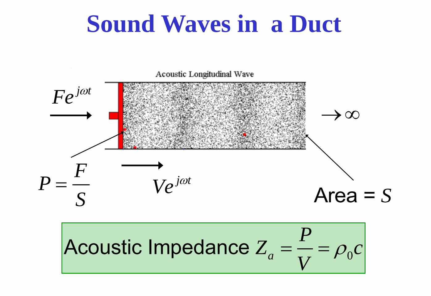
Acoustic Filters – Helmholtz Resonator
L
2S a
pS
12 4
pL S
VS
2
22
ˆ10log 1
ˆ4 1
TL
TL
dB
1
1.7 L L a
V

Acoustic Filters – Band-Pass
0 0.5 1 1.5 20
5
10
15
L
L
cSpS
ˆ c
p
Ss
S
2
2 21 1ˆ10log cos sin
ˆ4
TL kL s kLs
TL
dB
ˆ 10s 2
max
1 1ˆ10log
ˆ4
TL ss

Mufflers
ÃÃmÄÄ ÃÃVÄÄ o

Muffler Performance - effect of absorption

Acoustic Filters
ÃÃmÄÄ
ÃÃmÄÄ
ÃÃmÄÄ
ÃÃVÄÄ
local strain model
force
ÃÃkÄÄ
o

HIGHER-ORDER MODE PROPAGATION

MODES AND MODE SHAPE FUNCTIONS
At frequencies greater than f > 1.84c / D, higher order modes can
propagate. The general solution is a linear superposition of these ‘mode
shape function’ solutions:
1
,,,ˆn
kxi
mnmn
m
mnerAxrp
im
mnmmn erJr ,
11
,,,ˆnz
kxi
nxnynxny
ny
ezyAxzyp
nynz ny nzy z k y k z, cos cos
The resultant acoustic pressure in the duct is the weighted sum of fixed
pressure patterns across the duct cross section. Each of which
propagate axially along the duct at their characteristic axial phase
speeds.
Cylindrical duct Rectangular duct

EXAMPLES – RIGID CIRCULAR-DUCT MODES

Wave characteristics
Flexural structural
waves
Acoustic plane
waves
1
2 α c
α c

RESISITIVE SILENCERS

TYPES OF ACOUSTIC LINER
Single degree of freedom
(SDOF) cavity liner
Two degree of freedom
(2DOF) cavity liner
Bulk absorber liner

Partitions
(honeycomb)
Porous septum
Rigid backplate
Porous face-sheet
Fibrous
material Wave propagation
Bulk absorber
liner
Rigid backplate
Rigid backplate
Porous face-sheet
Porous face-sheet
Partitions
(honeycomb)
Two degree of freedom
(2DOF) liner
Single degree of freedom
(SDOF) liner
TYPES OF ACOUSTIC LINER

EXAMPLE OF A PRACTICAL LINER
(Photograph of a Rolls-Royce fan rig, from AIAA paper no. 2001-2268 )
Acoustic
lining
“Hard” liner
splices

Cavity liners (SDOF, 2DOF etc) consist of a sandwich construction. Each layer consists of a porous sheet and a cellular separator such as honeycomb. The backplate is rigid.
Cavity liners can be tuned to the frequency band of interest (by varying the partition depth). The bandwidth can be extended by the addition of more layers.
The acoustic properties of cavity liners depend on the resistance of the porous sheet(s), and the depth of the partition(s).
Cavity liners are “locally-reacting” liners, because the cellular structure prevents lateral sound propagation within the lining.
TYPES OF ACOUSTIC LINER
COMMENTS

Bulk absorber liners are a single layer construction. A fibrous material (e.g. glass
fibre, mineral wool etc) fills the gap between a porous face-sheet and a rigid
back plate.
Bulk absorbers tend to have the widest bandwidth, and are best suited to absorb
broadband and low-frequency noise.
Bulk absorbers are “bulk-reacting” liners, because sound can be transmitted
within the lining.
BULK ABSORBERS
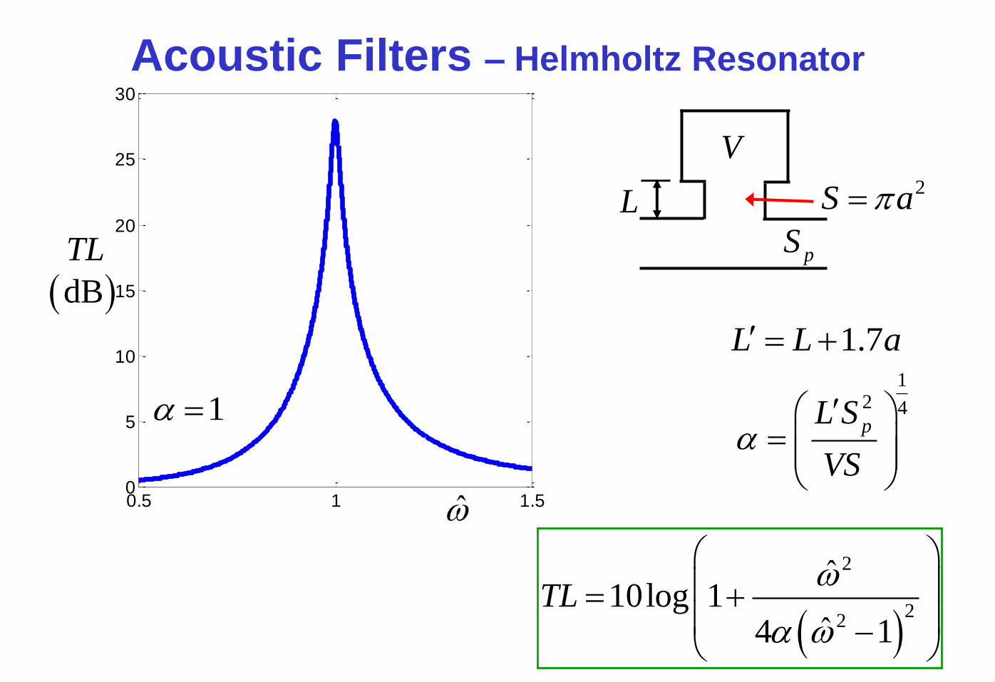
SPECIFIC ACOUSTIC IMPEDANCE
Specific acoustic impedance z, at a point in a single-frequency sound field, is the
complex ratio
At a boundary, the acoustic particle velocity is the component normal to the wall.
It is convenient to nondimensional the value of z as follows:
is the characteristic impedance of the fluid (e.g. air).
u
pz
ˆ
ˆ
Acoustic pressure – Acoustic particle velocity – tiep
ˆtieu
ˆ
R – Resistance
X – Reactance
Units or SI rayl 1msPa
iXRc
zZ
00
00c

CREMER OPTIMUM IMPEDANCE - EXAMPLE
mn contour map
10kb 0xM
1,0 nmmn ,
Optimum
impedance
iZ 25.195.2

EIGENVALUES – rigid duct
bkmnx
only0 m
10kb 4.0xM
Propagating
(cut-on) modes
21 xx MkM

EIGENVALUES – lined duct
iZ 5.00.1
10kb 4.0xM
bkmnx
only0 m

EXAMPLES: LINED-DUCT MODES

ABSORPTION OF SOUND IN LINED DUCTS
The transmission loss of mode (m,n) across a lined section of length l, in
decibels, is
The attenuation of a mode (m,n) is proportional to .
elk
lxp
xpmnxmn 1010 logIm20
ˆ
0ˆlog20
lmn6859.8
(The axial decay rate is denoted by .) mnxkIm
mn
mn

Modes near cut-off – well absorbed
Modes not near cut-off – poorly absorbed
LINER ATTENUATION VERSUS MODAL PROPAGATION ANGLE
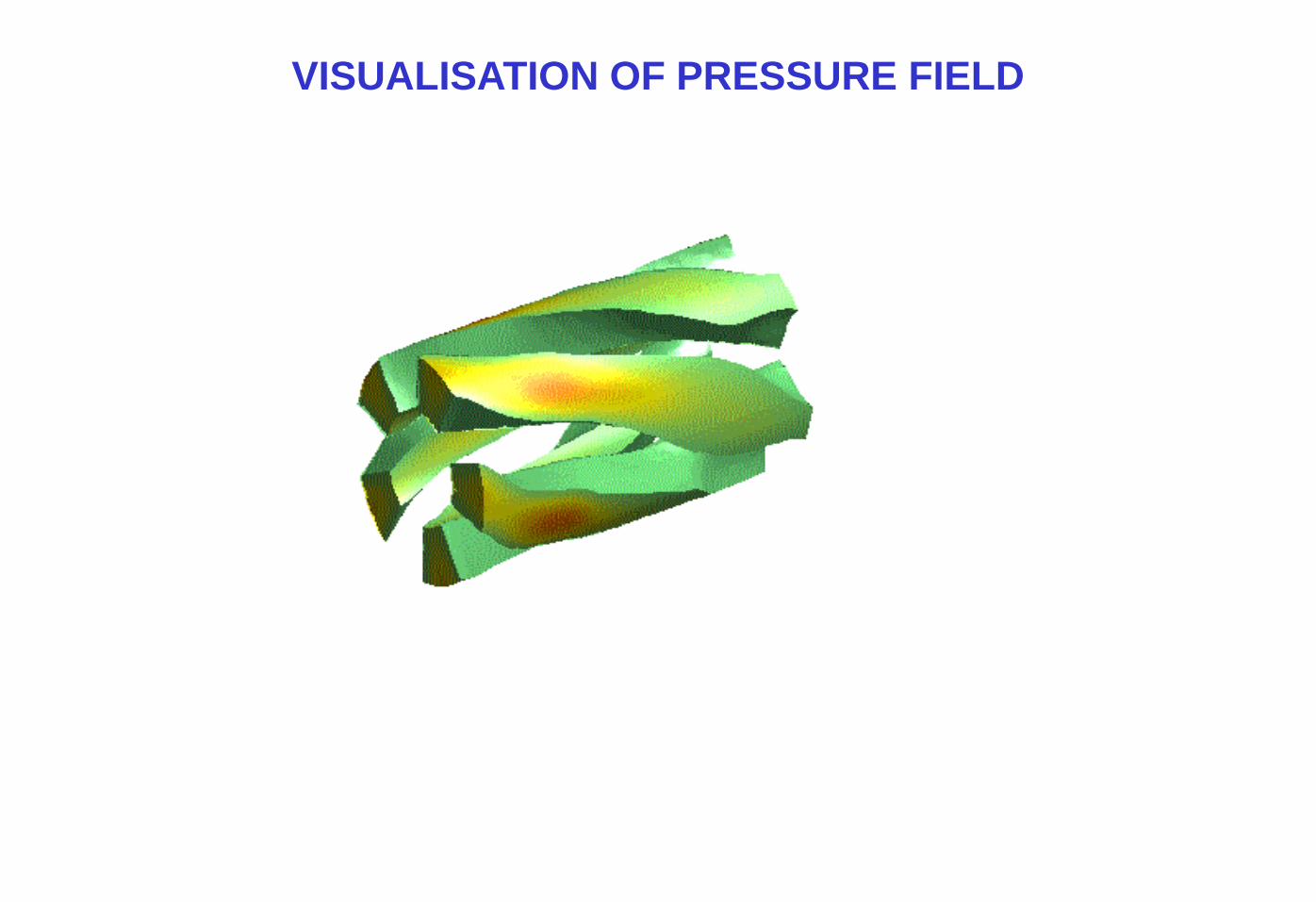
VISUALISATION OF PRESSURE FIELD
Top Related