


Languages
Pages
Legal

ANS meeting, Anaheim, CA (2008)
Laboratory for Thermal HydraulicsNuclear Energy and Safety
Droplet retention and Velocity Field in a Steam Generator
Ralf Kapulla, Steffen Danner, Salih Güntay, Abdel Dehbi
2008 ANS Annual MeetingDisneyland Hotel
Anaheim, California, June 8-12, 2008

ANS meeting, Anaheim, CA (2008)
Laboratory for Thermal HydraulicsNuclear Energy and Safety
Overview
Phase VI: Droplet retention in separator and dryer
Test section
Droplet retention
Test A: Collected mass retained
Test B: Local droplet size
Velocity field
Summary
ANS meeting, Anaheim, CA (2008)
Laboratory for Thermal HydraulicsNuclear Energy and Safety
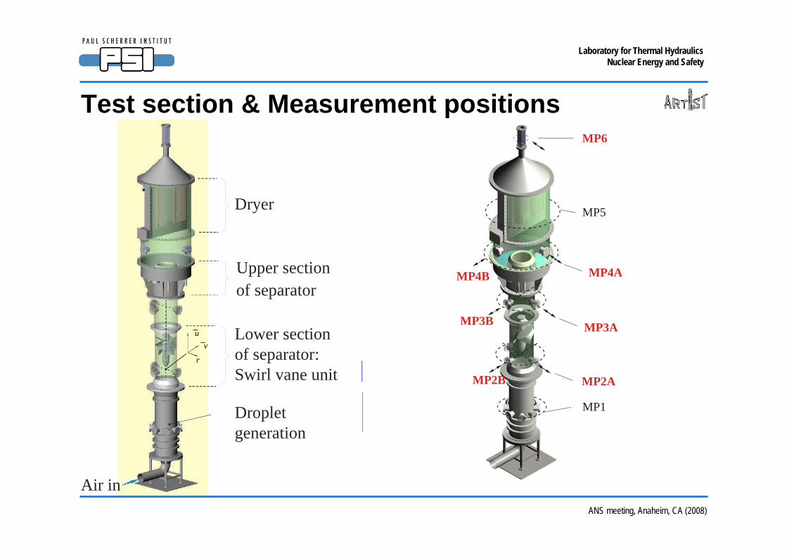
Test section & Measurement positions
Air in
Dryer
8 m
1.4 m
Upper sectionof separator
uv
r
Lower sectionof separator: Swirl vane unit
Dropletgeneration
MP1
MP2A
MP3A
MP4AMP4B
MP5
MP6
MP2B
MP3B
ANS meeting, Anaheim, CA (2008)
Laboratory for Thermal HydraulicsNuclear Energy and Safety
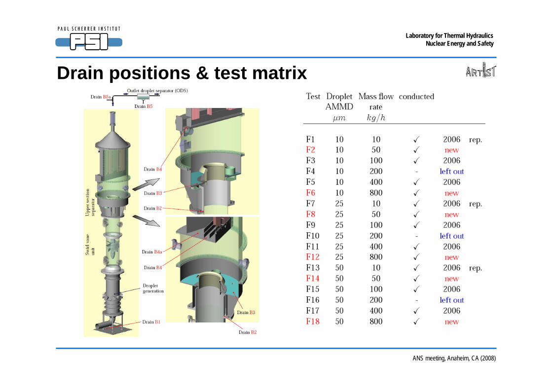
Drain positions & test matrix
8 m
1.4 m
ANS meeting, Anaheim, CA (2008)
Laboratory for Thermal HydraulicsNuclear Energy and Safety
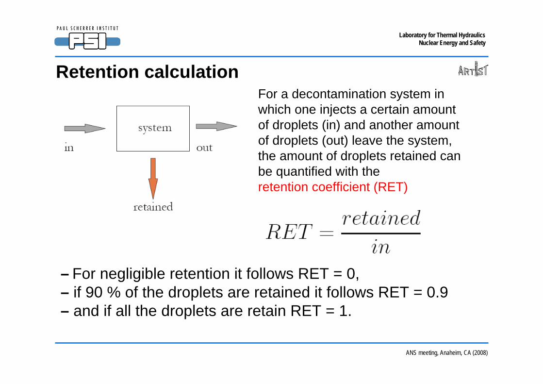
Retention calculation
8 m
1.4 m
For a decontamination system inwhich one injects a certain amountof droplets (in) and another amountof droplets (out) leave the system,the amount of droplets retained canbe quantified with the retention coefficient (RET)
– For negligible retention it follows RET = 0,– if 90 % of the droplets are retained it follows RET = 0.9– and if all the droplets are retain RET = 1.

ANS meeting, Anaheim, CA (2008)
Laboratory for Thermal HydraulicsNuclear Energy and Safety
Whole test section retention
8 m
1.4 m
20 40 600.0
0.2
0.4
0.6
0.8
1.0
1.2
BF050
BF400 BF800 BF050
BF400BF800
BF100
BF010
path: D:\kapulla\SWP55\ARTIST\PRC5\origin\Ret_Calculation\RET_Calculations_Results_DEHS.OPJName: RGIntegralRET02Sing
inte
gral
RET
[-]
AMMD [μm]– Retention increases with increasing AMMD – for all gas mass flow rates.
– Lower retention as gas mass flow rates increases. Reason: Gravitational settling.

ANS meeting, Anaheim, CA (2008)
Laboratory for Thermal HydraulicsNuclear Energy and Safety
Swirl vane retention
8 m
1.4 m
– Retention of swirl vane similar to whole test section.
– Retention characteristic dominated by swirl vane.
20 40 600.0
0.2
0.4
0.6
0.8
1.0
1.2
BF400 BF800 BF050
BF050
BF400BF800
BF100
BF10
path: D:\kapulla\SWP55\ARTIST\PRC5\origin\Ret_Calculation\RET_Calculations_Results_DEHS.OPJName: RGSVRET02
swir
l van
e RE
T [-
]
AMMD [μm]

ANS meeting, Anaheim, CA (2008)
Laboratory for Thermal HydraulicsNuclear Energy and Safety
Droplet separator upper part retention
8 m
1.4 m
– Retention of droplet sep. upper part is weak.
– No clear correlation between RET and AMMD.
20 40 600.0
0.2
0.4
0.6
0.8
1.0
1.2
( )
BF10 BF050 BF100 BF400 BF800
path: D:\kapulla\SWP55\ARTIST\PRC5\origin\Ret_Calculation\RET_Calculations_Results_DEHS.OPJName: RGDropletSRET02
ds u
pper
par
t RET
[-]
AMMD [μm]
Please note: x-axis scale (AMMD) according to test section inlet. Not according droplet separator upper part inlet.
ANS meeting, Anaheim, CA (2008)
Laboratory for Thermal HydraulicsNuclear Energy and Safety
20 40 600.0
0.2
0.4
0.6
0.8
1.0
1.2
BF10 BF050 BF100 BF400 BF800
path: D:\kapulla\SWP55\ARTIST\PRC5\origin\Ret_Calculation\RET_Calculations_Results_DEHS.OPJName: RGDryerRET02
drye
r RET
[-]
AMMD [μm]
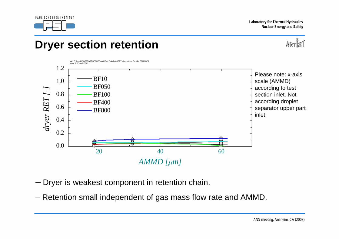
Dryer section retention
8 m
1.4 m
– Dryer is weakest component in retention chain.
– Retention small independent of gas mass flow rate and AMMD.
Please note: x-axis scale (AMMD) according to test section inlet. Not according droplet separator upper part inlet.
ANS meeting, Anaheim, CA (2008)
Laboratory for Thermal HydraulicsNuclear Energy and Safety
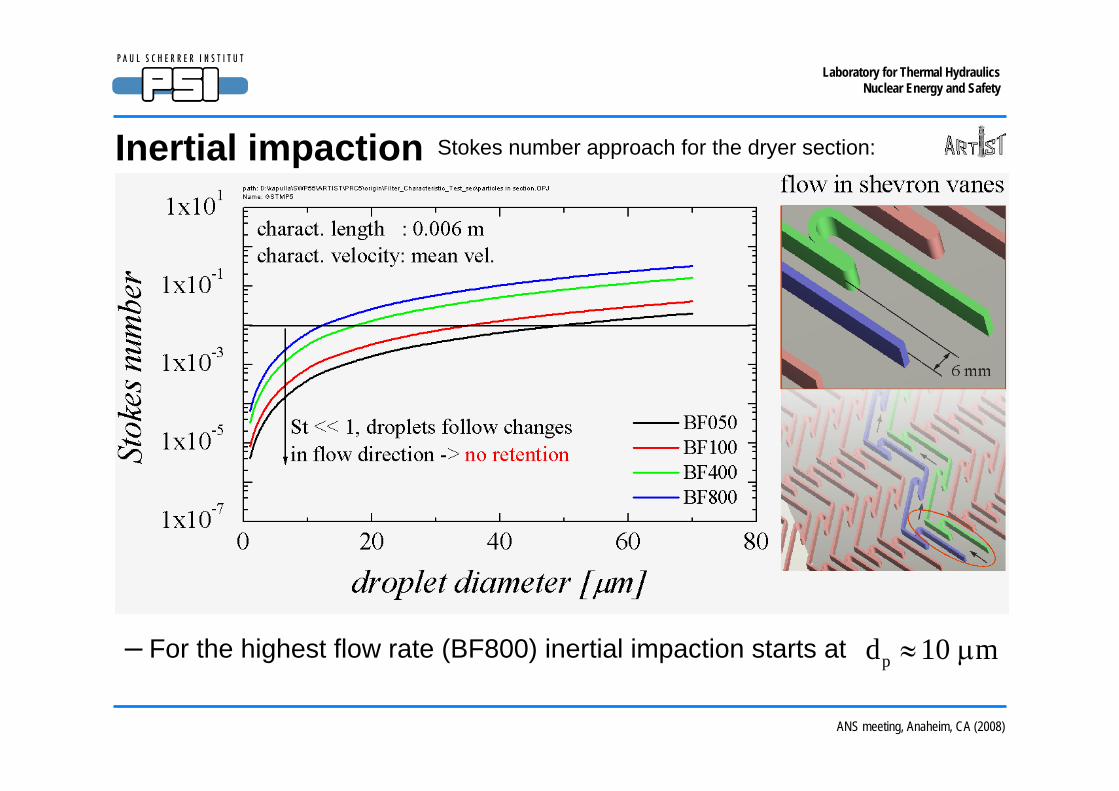
Inertial impaction
8 m
1.4 m
Stokes number approach for the dryer section:
– For the highest flow rate (BF800) inertial impaction starts at pd 10 m≈ μ

ANS meeting, Anaheim, CA (2008)
Laboratory for Thermal HydraulicsNuclear Energy and Safety
Local measurement positions & test matrix
8 m
1.4 m
To generate different droplet size spectra the DEHS mass flow rate was kept constant (1 l/h) and the nozzle gas mass flow rate was varied.
Higher air flow rates -> smaller droplets

ANS meeting, Anaheim, CA (2008)
Laboratory for Thermal HydraulicsNuclear Energy and Safety
0 20 40 60 80 1000
20
40
60
80
100
0 20 40 60 80 1000
20
40
60
80
100cw = 2 μm
x = 100 mm x = 160 mm x = 200 mm x = 220 mm
path: D:\kapulla\SWP55\ARTIST\PRC6\origin\.Droplets\MP3A_Tropfen_PDA_A_01.OPJName: PRC6_GBF100VCA10
BF100, A10
cum
mul
ativ
e vo
lum
e, %
diameter, μm
cw = 2 μm
x = 100 mm x = 160 mm x = 200 mm x = 220 mm
BF400, A10
cum
mul
ativ
e vo
lum
e, %
diameter, μm
Radial position dependence
8 m
1.4 m
Carrier gas mass flow rate 100 kg/h and 400 kg/h.
– Larger droplet content shows radial dependence. Larger large-droplet content as one moves radialy towards the wall.
– Radial dependence caused by rotational component of the flow field.
MP3A

ANS meeting, Anaheim, CA (2008)
Laboratory for Thermal HydraulicsNuclear Energy and Safety
Comparison: inlet & after swirl vane & after lid
8 m
1.4 m
0 20 40 60 80 100 120 1400
20
40
60
80
100cw = 2 μm
x = 250 mm (MP4A) x = 400 mm (MP4A) x = 450 mm (MP4A) x = 500 mm (MP4A)
---------------------------------------------- (MP2A) (MP3A)
path: D:\kapulla\SWP55\ARTIST\PRC6\origin\.Droplets\MP4A_Tropfen_PDA_A_01.OPJName: MP4ABF100VCA10
BF100, A10
cum
mul
ativ
e vo
lum
e, %
diameter, μm
Carrier gas mass flow rate 100 kg/h.
– Large droplet content is dramatically reduced.
– Weakly increasing larger droplet content for increasing radial position at after lid (MP4A)

ANS meeting, Anaheim, CA (2008)
Laboratory for Thermal HydraulicsNuclear Energy and Safety
Mean axial velocities: after swirl vane
8 m
1.4 m
-200 -100 0 100 2000.0
0.4
0.8
1.2
M12 BF800 BF600 BF400 BF200 BF100 BF050
MP3Apath: D:\kapulla\SWP55\ARTIST\PRC6\origin\.Velocities\MP3_Velocities_Vers_E_A_01.OPJName: M12_Axial_Vel
u [
m/s
]
radial distance [mm]– Low velocities in the core region (-100 < r < 100 mm) due to blockage by swirl vane.
– Increasing velocities outside the core flow for increasing carrier gas mass flow rates.

ANS meeting, Anaheim, CA (2008)
Laboratory for Thermal HydraulicsNuclear Energy and Safety
-200 -100 0 100 200-4
-3-2
-1
0
12
3
4 M12 BF800 BF600 BF400 BF200 BF100 BF050
MP3Apath: D:\kapulla\SWP55\ARTIST\PRC6\origin\.Velocities\MP3_Velocities_Vers_E_A_01.OPJName: M12_Radial_Vel
v [
m/s]
radial distance [mm]
Mean radial velocities: after swirl vane
8 m
1.4 m
– Swirl vane introduces strong transverse velocity component.
– Magnitude of transverse velocity above magnitude of axial velocity.
ANS meeting, Anaheim, CA (2008)
Laboratory for Thermal HydraulicsNuclear Energy and Safety
Centrifugal force after the swirl vane
8 m
1.4 m
ANS meeting, Anaheim, CA (2008)
Laboratory for Thermal HydraulicsNuclear Energy and Safety
Summary
8 m
1.4 m
- Retention increases with increasing AMMD.
- Due to gravitational settling low carrier mass flow rates have higher retention than high mass flow rates.
- Velocity field database is (i) available and ready for the (ii)comparison with CFD-calculations.
- Very promising, high quality droplet distribution database is (i) available and ready for the (ii) comparison with CFD-calculations.
Top Related