


Languages
Pages
Legal


In accordance with 49 CFR 395.22 (h) In-vehicle information
This manual must be kept in the vehicle
DRIVER USER MANUAL
For EZ-ELD queries contact Technical Support on: Tel: +1 (833) 994-3953
Email: [email protected]

2
Contents 1 Compliance Statement 7
2 EZ-ELD Kit Contents 10 3 Connector Options 11 3.1 Changing the connector 12 3.2 Inserting the new connector 13 3.3 Using the extension cable 15 4 Installation Instructions 20 5 What do the EZ-ELD Light and Sound Notifications Mean? 23 6 How to download the Stoneridge EZ-ELD® App 26 7 How to Pair your Smartphone or Tablet with EZ-ELD 26 7.1 Pairing for the first time 26 7.2 Clearing paired information from the EZ-ELD device 33 8 How to Use Scan and Drive™ 34 8.1 If the device has been previously paired 34 8.2 First time pairing using the QR code 35 9 Using the EZ-ELD App for the First Time 37 10 Driver Login 41 11 How to Login as a Co-Driver 43 12 Main Screen 46

3
13 Logs 52 13.1 How to review logs 52 13.2 How to edit existing ELD records 55 13.3 How to manually enter a new record 58 13.4 How to assign/claim unidentified driver records 59 13.5 How to edit and reassign driving time between team drivers 61 13.6 Confirm or reject edit requests 63 13.7 How to view Hours of Service violations (HoS warnings) 65 13.8 How to certify and send logs 67 13.9 How to view all driver logs 70 13.10 Understanding event records of logs 72 14 DOT Roadside Inspection 75 15 Malfunction and Diagnosis 79 16 DVIR—Driver-Vehicle Inspection Report 88 17 Engine Gauge Dashboard 91 18 Menu Settings 92 19 Chat/Messaging 93 20 IFTA/IRP 94 21 How to Log Out 101 22 Warranty 102
Note: Some screenshots shown in this manual may be different from what you see in the actual App depending on the platform or App version you are using. The most up to date version of this manual can be downloaded from our website at www.EZ-ELD.com.

4
Glossary
Term Definition
Data bus (also data
diagnostic bus or CAN
bus)
A means of transmitting data, in this case the link
from the ELD to the vehicle’s ECM (engine control
module).
DOT (Department of
Transportation)
The United States governmental department that
regulates transportation (including trucking and
commercial passenger transport).
DVIR (Driver Vehicle
Inspection Report)
A report a driver is required to prepare at the beginning and at the end of their working day listing any maintenance defects found with the vehicle or trailer.
ELD (Electronic Logging
Device)
A device for electronically recording driver logs.
This is the new term used in the 2015 DOT rule
mandating the use of electronic logs that comply
with certain standards.
FMCSA (Federal Motor
Carrier Safety
Administration)
An agency within the DOT that regulates the commercial transportation industry and tries to improve overall safety.

5
Term Definition
GPS (Global
Positioning System)
A radio navigation system that allows land, sea, and airborne users to determine their exact location, velocity, and time 24 hours a day, in all weather conditions, anywhere in the world.
HOS (Hours of Service) A professional driver’s time, as regulated by the DOT. Hours of Service are tracked using a log of time spent in various statuses: On Duty Not Driving, Driving, Off Duty and Sleeper Berth. Limits are placed on how much time a driver can work, and how much time he / she must take off to rest.
OBD (On-board
diagnostics)
An automotive term referring to a vehicle's self-diagnostic and reporting capability.
Protocols: CAN J1939,
ISO15765, J1587,
J1708
Industry standards for communicating data/
information within heavy, medium & light duty
vehicles.
RODS (Record of Duty
Status)
A log of a driver’s Hours of Service. This may be
recorded using a paper log (under certain
circumstances) or electronically using an ELD.

6
Term Definition
Scan and DriveTM A Stoneridge trademarked feature which allows
the driver to very easily pair and connect the EZ-
ELD® device to their Smartphone in one simple
step.
QR Code A machine-readable code consisting of an array of
black and white squares, typically used for storing
URLs or other information for reading by the
camera on a smartphone.

7
1 Compliance Statement
This equipment complies with Federal Communications Commission (FCC) and Industry Canada (IC) radiation exposure limits set forth for an uncontrolled environment.
This device has been certified as follows:
FCC ID: 2AKA8-ELD100A0
IC: 22098-ELD100A0
Model: ELD1.0
PMN: EZ-ELD
FCC Caution:
Changes or modifications not expressly approved by the party responsible for compliance could void the user's authority to operate the equipment.
8
FCC Statement:
This device complies with Part 15 of the FCC Rules. Operation is subject to the following two conditions:
1. this device may not cause harmful interference, and
2. this device must accept any interference received, including interference that may cause undesired operation.
This equipment has been tested and found to comply with the limits for a Class B digital device, pursuant to part 15 of the FCC Rules. These limits are designed to provide reasonable protection against harmful interference in a residential installation. This equipment generates, uses and can radiate radio frequency energy and, if not installed and used in accordance with the instructions, may cause harmful interference to radio communications. However, there is no guarantee that interference will not occur in a particular installation. If this equipment does cause harmful interference to radio or television reception, which can be determined by turning the equipment off and on, the user is encouraged to try to correct the interference by one or more of the following measures:
Reorient or relocate the receiving antenna.
Increase the separation between the equipment and receiver.
Connect the equipment into an outlet on a circuit different from that to which the receiver is connected.
Consult the dealer or an experienced radio/TV technician for help.

9
RSS-Gen & RSS-247 statement: This device complies with Industry Canada licence-exempt RSS standard(s). Operation is subject to the following two conditions:
1. this device may not cause interference, and 2. this device must accept any interference, including interference that
may cause undesired operation of the device.
Le présent appareil est conforme aux CNR d'Industrie Canada applicables aux appareils radio exempts de licence. L'exploitation est autorisée aux deux conditions suivantes :
1. l'appareil ne doit pas produire de brouillage, et 2. l'utilisateur de l'appareil doit accepter tout brouillage radioélectrique
subi, même si le brouillage est susceptible d'en compromettre le fonctionnement.
RSS-102 Statement: This equipment complies with Industry Canada radiation exposure limits set forth for an uncontrolled environment. Cet équipement est conforme à l'exposition aux rayonnements Industry Canada limites établies pour un environnement non contrôlé.

10
2 EZ-ELD Kit Contents
EZ-ELD Device with 9 Pin Connector attached
3 Additional On-Board Diagnostic Port (OBD) Connectors with end caps attached
Extension Cable
Quick Start Guide
Driver User Manual
2 QR Code Stickers
2 Vehicle Compliance Stickers
Circular Double Sided Adhesive Pad
EZ-ELD Device Connector cap when used with the Extension Cable
9 Pin Connector end cap
Do not use the device while the vehicle is in motion.
Mount the device in a fixed position which is visible to the driver when driving.
Always stop the vehicle safely to use the device.
Failure to do so may lead to serious injury or death.
Warning

11
3 Connector Options The EZ-ELD is shipped with the 9-pin OBD port connector already fitted. It also has 3 other connector options included in the kit:
6-pin
OBDII Light and Medium Duty Vehicles
OBDII for Volvo/Mack heavy duty vehicles
9 pin Connector 6 pin Connector OBDII Volvo/Mack Heavy duty vehicle
Connector
OBDII Light and Medium Duty Vehicles
Connector
EZ-ELD Device with 9 pin Connector
(Same for 6 pin) Connector)
EZ-ELD Device with OBDII Volvo/Mack Connector
(Same for OBDII Light and Medium Duty Vehicles
Connector)
12
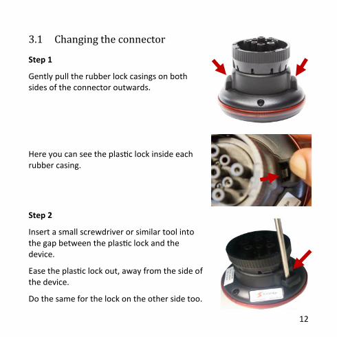
Step 1
Gently pull the rubber lock casings on both sides of the connector outwards.
Here you can see the plastic lock inside each rubber casing.
Step 2
Insert a small screwdriver or similar tool into the gap between the plastic lock and the device.
Ease the plastic lock out, away from the side of the device.
Do the same for the lock on the other side too.
3.1 Changing the connector

13
Step 3
Once both sides are unlocked, unplug the white connector from the main body of the device by pushing the small white lever on the cable connector.
3.2 Inserting the new connector
In this example we will insert one of the OBDII connectors.
Step 1
Remove the cap on the new connector to expose the wires by pulling out the rubber lock cases and plastic locks like you did before.
14
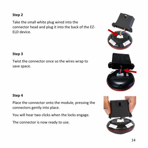
Step 2
Take the small white plug wired into the connector head and plug it into the back of the EZ-ELD device.
Step 3
Twist the connector once so the wires wrap to save space.
Step 4
Place the connector onto the module, pressing the connectors gently into place.
You will hear two clicks when the locks engage.
The connector is now ready to use.
15
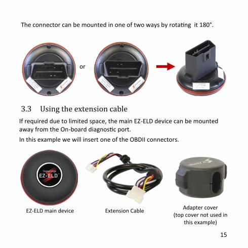
The connector can be mounted in one of two ways by rotating it 180°.
or
3.3 Using the extension cable
If required due to limited space, the main EZ-ELD device can be mounted away from the On-board diagnostic port.
In this example we will insert one of the OBDII connectors.
EZ-ELD main device Adapter cover
(top cover not used in this example)
Extension Cable
16
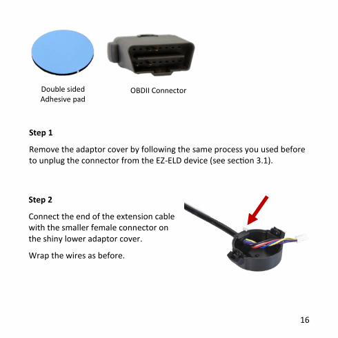
Step 1
Remove the adaptor cover by following the same process you used before to unplug the connector from the EZ-ELD device (see section 3.1).
Step 2
Connect the end of the extension cable with the smaller female connector on the shiny lower adaptor cover.
Wrap the wires as before.
Double sided Adhesive pad
OBDII Connector

17
Step 3
Connect the other larger connector end of the extension cable on the cover for the OBDII or 6-pin/9-pin.
Twist the wires around.
Step 4
Plug the end of the extension cable with the smaller female connector into the main connector of the EZ-ELD device.

18
Step 5
Carefully position the connector on the module and press gently until you hear two clicks.
Step 6
Plug the other larger end of the extension cable into the OBDII female connector.
Step 7
Position the connector on the end cap and press until you hear two clicks.

19
It should look like this - the EZ-ELD device has the long cable extension coming from it.
Step 8
Finally, stick the adhesive pad onto the bottom of the module for mounting in the cab.
Remove the backing from the adhesive pad and then mount the device in a position of your choosing.
20
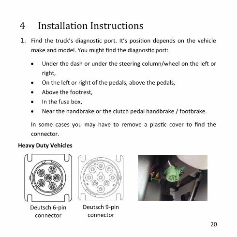
4 Installation Instructions
1. Find the truck’s diagnostic port. It’s position depends on the vehicle
make and model. You might find the diagnostic port:
Under the dash or under the steering column/wheel on the left or
right,
On the left or right of the pedals, above the pedals,
Above the footrest,
In the fuse box,
Near the handbrake or the clutch pedal handbrake / footbrake.
In some cases you may have to remove a plastic cover to find the
connector.
Heavy Duty Vehicles
Deutsch 6-pin connector
Deutsch 9-pin connector

21
OBDII Volvo/Mack Heavy Duty Vehicle Connector
OBDII Light and Medium Duty Vehicles Connector
Light and Medium duty vehicles
2. Attach the device to the vehicle’s diagnostic port.
In the case of the 9-pin or 6-pin connector, rotate the collar to line up the collar tabs with the matching slot on the diagnostic port. Press firmly until the EZ-ELD device is fully connected. Then rotate the collar clockwise until it locks.
In the case of the OBDII connector line up the connector so it exactly matches the diagnostic port in the vehicle. Press firmly until the EZ-ELD device is fully connected.
Note: During the App set up you will be required to enter the BT PIN code. This can be found on the label on the underside of the EZ-ELD module before you install it, on the QR code sticker or on the label on the back cover of this manual.

22
Example of a recommended installation:
Example of an unrecommended Installation:
Please always install the EZ-ELD device in a place that will not block or interfere with the safe operation of the vehicle pedals, obstruct the driver in any way or interfere with the safe operation of the vehicle. Please also avoid installing the EZ-ELD under metallic surfaces. If space is tight, please use the extension cable provided in the kit.

23
5 What do the EZ-ELD Light and Sound
Notifications Mean? LED/Buzzer Pattern Continuous
blink &
sound
LED
blinks 4
times/
Buzzer
LED
blinks
x 3
LED
blinks
x 2
LED
blinks
x 1
Solid 1
sound
2
sounds
3
sounds
GPS - - NOT OK
OK NOT OK
OK - - -
Data Bus (Can) - - NOT OK
NOT OK
OK OK - - -
First Connection Module Powered on
Initial installation auto set up (90 seconds)
Not paired and not connected
Press the pair button (Green Light—40 sec)
Bluetooth Connected IOS Connected
Android Connected Malfunction
Vehicle in motion, driver not logged in
Press and hold button appx. 5 secs. Delete
paired BT devices

24
Light & Sound Pattern Description
2 sounds
(Device is powered on)
When you attach the device to the vehicle’s
diagnostic port for the first time, the buzzer will
sound twice, showing that the device is
powered ON.
1 sound
(Bluetooth paired &
connected)
Press the button once and release, the LED will
blink green for about 40 seconds. The buzzer
will sound once, showing that the pairing and
connection were successful. Bluetooth is now
connected.
3 sounds
(Delete paired devices)
Press and hold the button on the EZ-ELD device
for about 5 seconds then release. The buzzer
will sound twice, paired devices have been
deleted.
Yellow LED The device is not paired and not connected.
Green LED The device is in pairing mode.
Blue LED Bluetooth is connected to an iOS (Apple) device.
White LED Bluetooth is connected to an Android device.

25
Light and Sound Pattern Description
Red LED
(Blinks four times)
Malfunction error detected.
Red LED
(Continuous blinking/sound)
The vehicle is in motion but the driver is
not connected to the EZ-ELD.
Red LED
(Initial installation auto setup—
90 seconds)
Whenever you attach the device to the
vehicle’s diagnostic port for the first
time, the device will start an auto setup
sequence for GPS and data bus
acquisition.
LED blinks three times (yellow,
green, white or blue)
GPS not working and Data Bus (CAN) not
working.
LED blinks twice (yellow, green,
white or blue)
GPS OK but Data Bus (CAN) not working.
LED blinks once (yellow, green,
white or blue)
GPS not working but Data Bus (CAN) OK.
LED solid (yellow, green, white
or blue)
GPS OK and Data Bus (CAN) OK. This is
normal operation.

26
6 How to download the Stoneridge
EZ-ELD® App You can download the Stoneridge EZ-ELD App for Android and iOS devices.
Search for “EZ-ELD” in the Google Play Store for Android phones/tablets, or search for “EZ-ELD” in the App Store for iPhones/iPads.
7 How to Pair your Smartphone or Tablet
with EZ-ELD
Step 1
Once you have downloaded the app from the Google Play or App Store, launch the EZ-ELD App by tapping the EZ-ELD icon on your phone or tablet.
Google Play and the Google Play logo are
trademarks of Google Inc. Apple and the Apple logo are trademarks of
Apple Inc., registered in the U.S. and other
countries.
7.1 Pairing for the first time

27
Step2
Bluetooth will turn on automatically.
Step 3
Allow the App to access the device.
Step 4
The LED light on the device should be yellow. This shows that the EZ-ELD device is not yet paired or connected.
Step 5
Tap PAIR NEW DEVICE.
Step 6
Enable GPS if prompted.

28
Step 7
If you see this screen, please make sure that the EZ
–ELD device is connected to the vehicle’s diagnostic
port and powered on so it can be found by the App.
Step 8
The EZ-ELD device will then appear on the screen.
Tap to select it.
If you have more than one device in range then
please select the device that you want to pair with
by checking the PIN number marked on the EZ-ELD
device label.

29
Step 9
You will be prompted to name your EZ-ELD device.
This name will be assigned to the EZ-ELD so you can
easily recognize it in future.
Step 10
Tap on PAIR AND CONNECT.
Step 11
You will then be prompted to press the EZ-ELD
Bluetooth control button on the device once
(shown on page 30)
Step 12
After you have pressed the Bluetooth control
button once and the LED on the device has turned
green then press OK on the App screen.

30
Bluetooth Control Button & LED Status Indicator
Location:
The Bluetooth control button allows the pairing of
new devices to the EZ-ELD (page 26) and also the
removal of all previously paired devices (page 33).
The LED status indicator displays basic diagnostic
information of the EZ-ELD device (page 23).
Step 13
In the App, enter the BT PIN
code as shown on the label
of the device, on the QR
code sticker or on the label
on the cover of this manual.
LED Status indicator
Bluetooth Control Button

31
Step 14
The buzzer will then sound once, indicating that the pairing was successful
and Bluetooth is now connected.
Step 15
The LED color will change to white or blue. Blue indicates the phone or
tablet you’re using is an iOS (Apple) device and white means you are using
an Android device.
Step 16
If the VIN number doesn't match your registration you
will be prompted after pairing. If your vehicle is not
listed, please contact your Fleet Manager to create it
and add it to your list of authorized vehicles. To
synchronize with the latest vehicles created in the Back
Office, your Smartphone or Tablet needs to be
connected to the internet.

32
Step 17
“Device” and “Server Status” are both green. Your
EZ-ELD device is connected and working correctly.
Device Status: Green – Bluetooth paired and
successfully connected.
Server Status: Green – You are connected to the
EZ-ELD Back office software server.
33
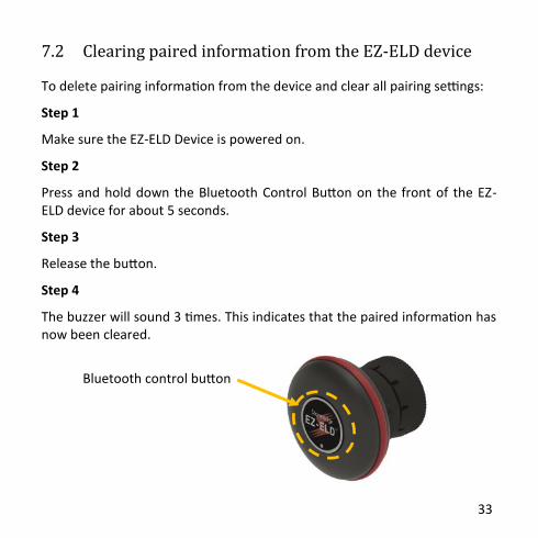
To delete pairing information from the device and clear all pairing settings:
Step 1
Make sure the EZ-ELD Device is powered on.
Step 2
Press and hold down the Bluetooth Control Button on the front of the EZ-ELD device for about 5 seconds.
Step 3
Release the button.
Step 4
The buzzer will sound 3 times. This indicates that the paired information has now been cleared.
7.2 Clearing paired information from the EZ-ELD device
Bluetooth control button

34
8 How to Use Scan and DriveTM
After initial pairing, Scan and Drive™ is a time saving feature that allows you to easily and quickly pair and connect the EZ-ELD device with your Smartphone or tablet.
8.1 If the device has been previously paired
Step 1
Tap on the QR Code image
Step 2
Scan the QR Code, holding your phone camera
steady so that the QR Code comes into
focus.

35
Step 3
The EZ-ELD Device is now paired and connected.
Now just log in as normal with your username and
password.
NOTE: To get a new QR Code label for your vehicle contact your Fleet Manager.
8.2 First time pairing using the QR Code
Step 1
Follow steps 1 and 2 in the previous section.
Step 2
The App will recognize that you are connecting the EZ-ELD device for the first time, and will take you to the next screen “Device Info”.
36
Step 5
Follow the same steps as shown in “How to pair your Smartphone or tablet with EZ-ELD” (section 7.1.11 to 7.1.17).
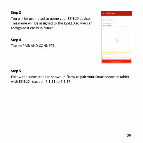
Step 3
You will be prompted to name your EZ-ELD device. This name will be assigned to the EZ-ELD so you can recognize it easily in future.
Step 4
Tap on PAIR AND CONNECT.

37
9 Using the EZ-ELD App for the First Time
Invitation Email
The System Administrator or
Authorized Support Personnel who
administer the Back Office System
must send an ‘Invitation Email’ to each
driver who works for the company.
This is a security measure to ensure
that only authorized drivers are invited
to join the Company’s ELD system.
This email contains an invitation key
(or unique access code) that the driver
must enter to start the creation of
their own, unique, user account.

38
Step 1
Pair and connect the device.
Step 2
Tap USE INVITATION
Step 3
Type or COPY and PASTE the invitation key from
the Fleet Manager email into the indicated field.
Step 4
Tap JOIN.

39
Step 5
Fill in all required fields to register (user name,
password, confirm password etc.) and Tap SAVE.
NOTE: Your email address must match the one
used in the email invitation from your Fleet
Manager.
Step 6
To associate a picture with your account, tap on
the camera icon and choose Camera or Gallery.
Select your picture.

40
Step 7
To add an electronic signature, tap SIGNATURE
underneath the “Confirm Password” box.
Step 8
Use your finger or a stylus to write your signature in
the white box and tap SAVE SIGNATURE. If you need
to change it, tap CLEAR PAD and start again. You can
change the signature later if necessary.
Step 9
After registering, you will be automatically logged into
your account.

41
Step 1
Enter your Username and Password and tap
LOGIN.
Step 2
Tap to select the motor carrier company you were
invited to join.
NOTE: If a motor carrier configures a driver
account as exempt from ELD use, the EZ-ELD will
advise the driver of this during the login / logout
process.
If a motor carrier changes the configuration
settings for the driver duty status categories (i.e.
allow authorized personal use of CMV or yard
moves), the EZ-ELD will also notify the account
user.
10 Driver Login

42
Step 3
Enter CMV Power Unit Number, Trailer Number(s)
and Shipping Document Number.
NOTE: If there are any previous records on the EZ-
ELD (excluding the current 24-hour period) that
require certification or re-certification, you will be
prompted to certify those records in ‘Previous Logs’
when you log in.
EZ-ELD will automatically obtain the VIN number
from the engine’s ECM, and match it with the
vehicle registered by the Fleet Manager. If the VIN
number is not available in the vehicle data bus, the
App will show a field to enter the VIN number. If the
VIN number you have doesn't match the previous
one registered in the Back Office software, please
contact your Fleet Manager.

43
11 How to Log in as a Co-Driver
Step 1
Tap the menu button on the top left side of the
main screen.
Step 2
Tap LOGIN.
44
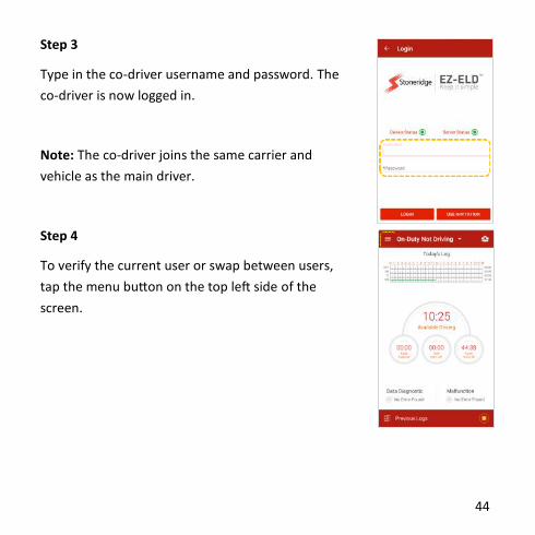
Step 3
Type in the co-driver username and password. The
co-driver is now logged in.
Note: The co-driver joins the same carrier and
vehicle as the main driver.
Step 4
To verify the current user or swap between users,
tap the menu button on the top left side of the
screen.
45
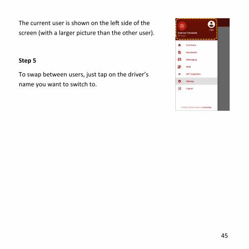
The current user is shown on the left side of the
screen (with a larger picture than the other user).
Step 5
To swap between users, just tap on the driver’s
name you want to switch to.

46
12 Main Screen
DOT Inspection Tap to start the data transfer to authorized safety officials during a roadside safety inspection or otherwise.
Current Day HOS Graph Current day 24 hour period graph grid.
Property Carrying Countdown Timers "Available Driving" refers to the 11-Hour Maximum Driving Limit within the 14-Hour Consecutive Driving Window.
"Break Required" refers to the 8 Consecutive Working Hours Limit, and the Thirty-Minute Rest Break before driving.
"Shift Hour Left" refers to the 14-Hour Driving Window limit, also known as the “Daily Limit”, taking into account the sleeper-berth extensions.
"Cycle Hour Left" refers to the 70 hour/8day or 60 hour/7 day limits cycle rule.
47
Please note: The EZ-ELD does a best effort calculation to support Commercial motor drivers and carriers in their compliance with (49 CFR part 395) Federal hours of service rules under part 395. Stoneridge shall not be held responsible for any defects or shortcomings in this function. The EZ-ELD takes the following into account in its internal calculations, it synchronizes with the engine control module to automatically record engine power status, vehicle motion status indicated driving and other data provided by user input. Time is recorded and synchronized with UTC (coordinated universal time) General calculations are implemented against 49 CFR part 395 in compliance with driving time, on duty (not driving)/off duty time and sleeper berth, as well as yard moves and personal use. The data presented by EZ-ELD may in some cases differ from what regulation states, especially in (but not limited to) some special cases:
Malfunctioning ELD device
Timing compliance malfunction
ELD data recording compliance malfunction Advisory note: In all cases where malfunctions happen and eRODs are not possible, paper RODS are required to be filled in until the malfunction is rectified.
48
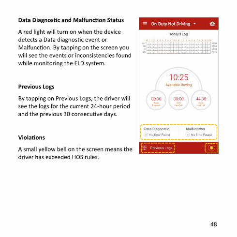
Data Diagnostic and Malfunction Status
A red light will turn on when the device detects a Data diagnostic event or Malfunction. By tapping on the screen you will see the events or inconsistencies found while monitoring the ELD system.
Previous Logs
By tapping on Previous Logs, the driver will see the logs for the current 24-hour period and the previous 30 consecutive days.
Violations
A small yellow bell on the screen means the driver has exceeded HOS rules.
49
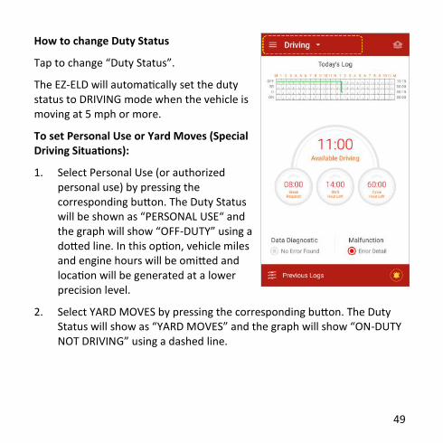
How to change Duty Status
Tap to change “Duty Status”.
The EZ-ELD will automatically set the duty status to DRIVING mode when the vehicle is moving at 5 mph or more.
To set Personal Use or Yard Moves (Special Driving Situations):
1. Select Personal Use (or authorized personal use) by pressing the corresponding button. The Duty Status will be shown as “PERSONAL USE“ and the graph will show “OFF-DUTY” using a dotted line. In this option, vehicle miles and engine hours will be omitted and location will be generated at a lower precision level.
2. Select YARD MOVES by pressing the corresponding button. The Duty Status will show as “YARD MOVES” and the graph will show “ON-DUTY NOT DRIVING” using a dashed line.

50
If the vehicle stops or does not move for 5 consecutive minutes, the EZ-ELD will prompt the driver to continue with their current DRIVING duty status or enter a new duty status, “ON DUTY NOT DRIVING”.
When the Duty Status is set to DRIVING, and the vehicle has not moved for 5 consecutive minutes, you will be prompted to confirm the DRIVING status or to change it.
If you do not acknowledge this prompt within 1 minute, the Duty Status will automatically change to ON-DUTY NOT DRIVING.

51
Status Descriptions Tap to change Duty Status: ON = On-Duty Not Driving OFF = Off-Duty D = Driving SB = Sleeper Berth YM = Yard Moves PC = Authorized Personal Use of Commercial Motor Vehicle (CMV)
Note: You will only see the Yard Moves and Personal Use of a CMV option if the Fleet Manager has authorized this in the Back Office software.

52
13 Logs
13.1 How to review logs
Step 1
Tap the graph to display the Driver Log for the current 24-hour period.
Step 2
Swipe your finger on the logs to scroll up and down.
You can review the current 24-hour period on the screen.
Step 3
Swipe your finger to the right or left to navigate to “VIOLATIONS” and “CERTIFY” Logs.
Step 4
Tap on the icon to edit an event.
Step 5
Tap on the icon to add missing events.

53
Step 6
Tap on ALL LOGS to see all types of events.

54
Step 7
In the main screen, tap “Previous Logs” to display the logs for the current 24-hour period, and the previous 30 consecutive days.
Step 8
Tap your finger on the desired date to display the log for that day.

55
13.2 How to edit existing ELD records
Step 1
Tap on the icon to edit an existing record.
Step 2
You can edit the driver duty status by tapping on the icons OFF (Off Duty), SB (Sleeper Berth), D (Driving)*, ON (On-Duty Not Driving).
To change the start time and duration, tap on the ‘start time’ field.
You can also tap on the cursor on the graph and swipe right or left to set the start time and duration.
*ELD automatically generated driving events CANNOT BE EDITED. In addition, any other duty status edit that would cause any subsequent reduction of recorded Driving time is not permitted.
56
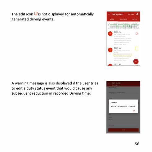
The edit icon is not displayed for automatically generated driving events.
A warning message is also displayed if the user tries to edit a duty status event that would cause any subsequent reduction in recorded Driving time.

57
Step 3
If prompted, fill in the required information and tap SAVE.
Step 4
The event is now created or changed.
Step 5
Confirm the information. The data origin will change to “Edited” or “Entered by the Driver”. The graph will change to show the updated information.
NOTE: You cannot edit or make a manual entry for the following:
Automatically recorded Driving events created by the EZ-ELD.
Any other event edit that would cause any subsequent reduction in
recorded Driving time.
An intermediate log.
Driver’s login/logout activity.
CMV’s engine power up/shutdown.
ELD Malfunctions and Data Diagnostic events.

58
13.3 How to manually enter a new record
Step 1
Tap on the icon to add a new manual record.
Step 2
You can add a new driver status record by tapping on the icons OFF (Off-Duty), SB (Sleeper Berth), D (Driving) or ON (On-Duty Not Driving).
To enter the start time tap on the ‘start time’ field.
To enter a corresponding end time for the new record turn on the ‘add interval to duty status’ switch or use the cursors on the graph.
Step 3
Tap SAVE.
Step 4
The data origin will change to “Edited” or “Entered by the Driver”.
Step 5
The graph will then change to show the updated information.

59
13.4 How to assign/claim unidentified driver records
Step 1
To access unidentified driver records, tap “Previous Logs” at the bottom of the screen.
Step 2
Swipe left or right, or tap UNIDENTIFIED LOGS.

60
Step 3
Review the unassigned driving time.
Step 4
Tap icon to confirm that you were driving and
assign that record to you.
Step 5
Or tap icon to reject the unassigned driving time.
NOTE: When you log in as a Driver you will always be prompted to confirm or reject any unassigned driving time associated with the vehicle you are in.

61
13.5 How to edit and reassign driving time between team
drivers
Step 1
To correct errors and reassign driving time, tap “Previous Logs”.
Step 2
Swipe up or down to find and select the date that needs to be reviewed.

62
Step 3
Tap the log that needs correcting.
Step 4
Select icon and this will send the log to the driver/co-driver that was signed in at the same time.
Step 5
Add a note, then confirm the change and tap TRANSFER.

63
13.6 Confirm or reject edit requests
Step 1
Tap “Previous Logs” to review edit requests.
Step 2
Swipe up or down to find and select the date that needs to be reviewed. Tap DRIVER EDIT or CARRIER EDIT.

64
Step 3
Tap the CONFIRM button to accept the change, or the REJECT button to refuse the change.
Step 4
If the change is rejected, the original record stays the same.
Step 5
If the change is accepted, the changes will appear in the graph and events history list.

65
13.7 How to view Hours of Service violations (HoS warnings)
Step 1
Tap “Previous Logs” or icon to review the violations.
Step 2
Select the date next to the log where the violations icon appears.

66
Step 3
Swipe to the left, or tap VIOLATIONS at the top of the screen.
Step 4
Check the HOS violations and certify them. See section 13.8 for details.

67
13.8 How to certify and send logs
Step 1
Tap “Previous Logs”.
Step 2
Scroll up or down to find and select the date that needs to be certified.
The icon shows that the driver’s records were certified.

68
Step 3
Select the date, review the log(s) and swipe your finger left, or tap CERTIFY.
Step 4
Tap the AGREE button to certify the driver’s records or NOT READY to do so later.

69
Note: Driver certification of the daily logs is REQUIRED BY LAW. If there any records that need certification or re-certification, the EZ-ELD will indicate the required action by the Driver when they login or logout.

70
13.9 How to view all driver logs
Step 1
To see all logs or detailed logs, such as certification, login, logout, engine on, etc. tap “Previous Logs”.
Step 2
Scroll up or down to find and select the date you want to view the log for.

71
Step 3
After selecting the date, tap the icon to view
all logs recorded, such as Login, Logout, Power up,
Shutdown, Intermediate logs, Special Driving
situation, Certification, Malfunction and Data
Diagnostics.

72
13.10 Understanding event records of logs
Icon Event type Information shown in Logs and All
Logs
Driver’s duty status
changed to “Driving”
Date, Time, Location, Event Record Origin, Accumulated Vehicle Miles, Elapsed Engine Hours and Event Record Status.
Driver’s duty status
changed to “Sleeper Berth”
Date, Time, Location, Event Record
Origin, Accumulated Vehicle Miles,
Elapsed Engine Hours and Event
Record Status.
Driver’s duty status
changed to “Off-duty”
Date, Time, Location, Event Record
Origin, Accumulated Vehicle Miles,
Elapsed Engine Hours and Event
Record Status.
Driver’s duty status
changed to “On-duty not
driving”
Date, Time, Location, Event Record
Origin, Accumulated Vehicle Miles,
Elapsed Engine Hours and Event
Record Status.
D
SB
OFF
ON
73
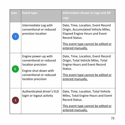
Icon Event type Information shown in Logs and All
Logs
Intermediate Log with conventional or reduced precision location
Date, Time, Location, Event Record Origin, Accumulated Vehicle Miles, Elapsed Engine Hours and Event Record Status.
This event type cannot be edited or entered manually.
Engine power-up with conventional or reduced location precision
Engine shut-down with conventional or reduced location precision
Date, Time, Location, Event Record Origin, Total Vehicle Miles, Total Engine Hours and Event Record Status.
This event type cannot be edited or entered manually.
Authenticated driver’s ELD login or logout activity
Date, Time, Location, Total Vehicle Miles, Total Engine Hours and Event Record Status.
This event type cannot be edited or entered manually.
I
E
L

74
Icon Event type Information shown in Logs and
All Logs
Special Driving Situation:
Driver indicates “Authorized Personal Use of CMV “
Driver indicates ”Yard Moves”
Driver indication for PC and YM cleared
Date, Time, Location, Event Record Origin, Accumulated Vehicle Miles, Elapsed Engine Hours and Event Record Status.
Driver’s Certification of a daily Date, Time, Location, Time Zone Offset from UTC
Data Diagnostic event logged
or cleared
Date, Time, Location, Event Record Origin, Data Diagnostic Code and Event Record Status.
This event type cannot be edited or entered manually.
An ELD Malfunction logged or
cleared
Date, Time, Location, Event Record Origin, Data Diagnostic Code and Event Record Status.
This event type cannot be edited or entered manually.
SDS
C
DD
M

75
14 DOT Roadside Inspection
The EZ-ELD has a standard single-step process so you can quickly send driver records to authorized safety officials during a roadside inspection.
Step 1
To do this either:
Tap the icon in the top right corner of the main screen,
From the left side menu, tap “DOT Inspection”, or
In the Logs screen, tap the icon.

76
Step 2
Choose the option you wish to select from INSPECTION
ON SCREEN, SEND TO EMAIL or SEND TO WEBSERVICE
and then tap that button to start the inspection on
screen or data transfer process.

77
By clicking INSPECTION ON SCREEN, the EZ-ELD will then display the FMCSA
mandated information header, HOS graphic and a detailed list of events. The
information is available for the current 24-hour period and each of the
previous 7 consecutive days. Any unidentified driver profile events for that
vehicle will also be presented at the bottom of the event list and also
through the shortcut button.
78
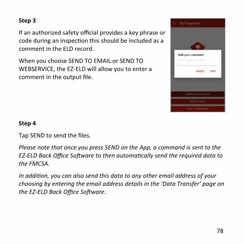
Step 3
If an authorized safety official provides a key phrase or code during an inspection this should be included as a comment in the ELD record.
When you choose SEND TO EMAIL or SEND TO WEBSERVICE, the EZ-ELD will allow you to enter a comment in the output file.
Step 4
Tap SEND to send the files.
Please note that once you press SEND on the App, a command is sent to the EZ-ELD Back Office Software to then automatically send the required data to the FMCSA.
In addition, you can also send this data to any other email address of your choosing by entering the email address details in the ‘Data Transfer’ page on the EZ-ELD Back Office Software.
79
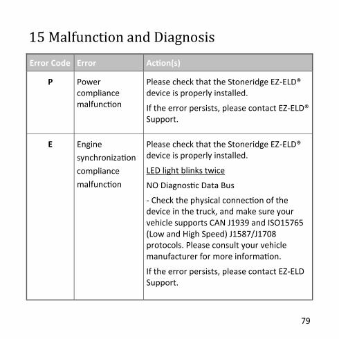
15 Malfunction and Diagnosis
Error Code Error Action(s)
P Power compliance malfunction
Please check that the Stoneridge EZ-ELD® device is properly installed.
If the error persists, please contact EZ-ELD® Support.
E Engine
synchronization
compliance
malfunction
Please check that the Stoneridge EZ-ELD® device is properly installed.
LED light blinks twice
NO Diagnostic Data Bus
- Check the physical connection of the device in the truck, and make sure your vehicle supports CAN J1939 and ISO15765 (Low and High Speed) J1587/J1708 protocols. Please consult your vehicle manufacturer for more information.
If the error persists, please contact EZ-ELD Support.

80
Error Code Error Action(s)
T Timing
compliance
malfunction
Please check that the Stoneridge EZ-ELD® device is properly installed.
LED light blinks once — NO GPS Signal
- Connect the extension cable included in the kit. Install the device in a location where it is visible and more likely to pick up a GPS signal. Avoid installing or placing the device under metallic surfaces.
If the error persists, please contact EZ-ELD Support.
L Positioning
compliance
malfunction
Please check that the Stoneridge EZ-ELD® device is properly installed.
LED light blinks once — NO GPS Signal
- Connect the extension cable included in the kit. Install the device in a location where it is visible and more likely to pick up a GPS signal. Avoid installing or placing the device under metallic surfaces.
If the error persists, please contact EZ-ELD Support.

81
Error Code Error Action(s)
R Data record
compliance
malfunction
Please contact EZ-ELD Support.
S Data transfer
compliance
malfunction
Please make sure that your network or internet connection is working properly.
If the error persists, please contact EZ-ELD Support.
O Other ELD
detected
malfunction
Please contact EZ-ELD Support.

82
Error Code Error Action(s)
1 Power data
diagnostic error
Please check that the Stoneridge EZ-ELD® device is properly installed.
If the error persists, please contact EZ-ELD Support.
2 Engine
syncronization
data diagnostic
error
Please check that the Stoneridge EZ-ELD® device is properly installed.
LED light blinks twice
NO Diagnostic Data Bus
- Check the physical connection of the device in the truck, and make sure your vehicle supports CAN J1939 and ISO15765 (Low and High Speed) J1587/J1708 protocols. Please consult your vehicle manufacturer for more information.
If the error persists, please contact EZ-ELD Support.

83
Error Code Error Action(s)
3 Missing required
data elements
data diagnostic
error
Please check that the Stoneridge EZ-ELD® device is properly installed.
LED light blinks twice
NO Diagnostic Data Bus
- Check the physical connection of the device in the truck, and make sure your vehicle supports CAN J1939 and ISO15765 (Low and High Speed) J1587/J1708 protocols. Please consult your vehicle manufacturer for more information.
LED light blinks once
NO GPS Signal
- Connect the extension cable included in the kit. Install the device in a location where it is visible and more likely to pick up a GPS signal (i.e. not hidden) with a better view of the sky. Avoid installing or placing the device under metallic surfaces.
If the error persists, please contact EZ-ELD Support.
84
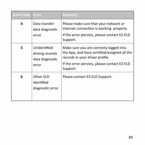
Error Code Error Action(s)
4 Data transfer
data diagnostic
error
Please make sure that your network or internet connection is working properly.
If the error persists, please contact EZ-ELD Support.
5 Unidentified
driving records
data diagnostic
error
Make sure you are correctly logged into the App, and have certified/assigned all the records in your driver profile.
If the error persists, please contact EZ-ELD Support.
6 Other ELD
identified
diagnostic error
Please contact EZ-ELD Support.

85
§ 395.34 ELD malfunctions and data diagnostic events
(a) Recordkeeping during ELD malfunctions. In case of an ELD malfunction,
a driver must do the following:
(1) Note the malfunction of the ELD and provide written notice of the
malfunction to the motor carrier within 24 hours;
(2) Reconstruct the record of duty status for the current 24-hour period and
the previous 7 consecutive days, and record the records of duty status on
graph-grid paper logs that comply with § 395.8, unless the driver already
possesses the records or the records are retrievable from the ELD; and
(3) Continue to manually prepare a record of duty status in accordance
with § 395.8 until the ELD is serviced and brought back into compliance with
this subpart.
(b) Inspections during malfunctions. When a driver is inspected for hours of
service compliance during an ELD malfunction, the driver must provide the
authorized safety official the driver's records of duty status manually kept as
specified under paragraphs (a)(2) and (3) of this section.
(c) Driver requirements during ELD data diagnostic events. If
an ELD indicates that there is a data inconsistency that generates a data
diagnostic event, the driver must follow the motor carrier's
and ELD provider's recommendations in resolving the data inconsistency.
86
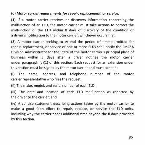
(d) Motor carrier requirements for repair, replacement, or service.
(1) If a motor carrier receives or discovers information concerning the
malfunction of an ELD, the motor carrier must take actions to correct the
malfunction of the ELD within 8 days of discovery of the condition or
a driver's notification to the motor carrier, whichever occurs first.
(2) A motor carrier seeking to extend the period of time permitted for
repair, replacement, or service of one or more ELDs shall notify the FMCSA
Division Administrator for the State of the motor carrier's principal place of
business within 5 days after a driver notifies the motor carrier
under paragraph (a)(1) of this section. Each request for an extension under
this section must be signed by the motor carrier and must contain:
(i) The name, address, and telephone number of the motor
carrier representative who files the request;
(ii) The make, model, and serial number of each ELD;
(iii) The date and location of each ELD malfunction as reported by
the driver to the carrier; and
(iv) A concise statement describing actions taken by the motor carrier to
make a good faith effort to repair, replace, or service the ELD units,
including why the carrier needs additional time beyond the 8 days provided
by this section.

87
(3) If FMCSA determines that the motor carrier is continuing to make a good
faith effort to ensure repair, replacement, or service to address the
malfunction of each ELD, FMCSA may allow an additional period.
(4) FMCSA will provide written notice to the motor carrier of its
determination. The determination may include any conditions that FMCSA
considers necessary to ensure hours-of-service compliance. The
determination shall constitute a final agency action.
(5) A motor carrier providing a request for extension that meets the
requirements of paragraph (d)(2) of this section is deemed in compliance
with § 395.8(a)(1)(i) and (a)(2) until FMCSA makes an extension
determination under this section, provided the motor carrier and driver
continue to comply with the other requirements of this section.

88
Step 1
Tap the menu button at the top left hand side of the screen.
Step 2
Select DVIR from the menu.
16 DVIR - Driver-Vehicle Inspection Report
89
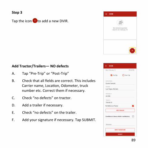
Step 3
Tap the icon to add a new DVIR.
Add Tractor/Trailers— NO defects
A. Tap “Pre-Trip” or “Post-Trip”
B. Check that all fields are correct. This includes Carrier name, Location, Odometer, truck number etc. Correct them if necessary.
C. Check “no defects” on tractor.
D. Add a trailer if necessary.
E. Check “no defects” on the trailer.
F. Add your signature if necessary. Tap SUBMIT.
90
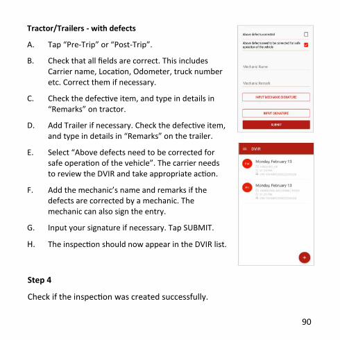
Tractor/Trailers - with defects
A. Tap “Pre-Trip” or “Post-Trip”.
B. Check that all fields are correct. This includes Carrier name, Location, Odometer, truck number etc. Correct them if necessary.
C. Check the defective item, and type in details in “Remarks” on tractor.
D. Add Trailer if necessary. Check the defective item, and type in details in “Remarks” on the trailer.
E. Select “Above defects need to be corrected for safe operation of the vehicle”. The carrier needs to review the DVIR and take appropriate action.
F. Add the mechanic’s name and remarks if the defects are corrected by a mechanic. The mechanic can also sign the entry.
G. Input your signature if necessary. Tap SUBMIT.
H. The inspection should now appear in the DVIR list.
Step 4
Check if the inspection was created successfully.
91
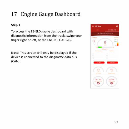
17 Engine Gauge Dashboard
Step 1
To access the EZ-ELD gauge dashboard with diagnostic information from the truck, swipe your finger right or left, or tap ENGINE GAUGES.
Note: This screen will only be displayed if the device is connected to the diagnostic data bus (CAN).

92
18 Menu Settings
Step 1
Tap the Menu button at the top left of your screen.
Step 2
Tap Settings in the left-hand menu.
Step 3
Tap “My Profile” to update driver’s information such as Driver License, State, Phone number, email, Signature, etc.
Step 4
Tap “Licence Agreement” to read the End User License Agreement.
Step 5
Tap “About” to check the App version and other information such FCC ID, IC ID, etc.

93
19 Chat/Messaging
Step 1
To send a message to the Fleet Manager, tap on the left-hand menu and select “Messaging”.
Step 2
Choose the Carrier you wish to contact.
Step 3
Type your message above the line which says “Send Message”, and tap SEND.

94
20 IFTA (International Fuel Tax Agreement) /IRP (International Registration Plan)*
20.1 How to add a new fuel purchase
Step 1
Tap the menu button on the top left of the main screen.
Step 2
Tap “Fuel”
*The International Registration Plan (IRP) is a US-based registration reciprocity agreement among states of the United States and provinces of Canada.
EZ-ELD makes IFTA and IRP reporting fast and easy. Use the
app to record all your fuel purchases and the EZ-ELD will automatically generates mileage and fuel consumption
reports per vehicle and per state, as well as IFTA 101 and
IFTA 100 reports.
95
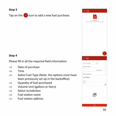
Step 3
Tap on the icon to add a new fuel purchase.
Step 4
Please fill in all the required field information.
Date of purchase
Time
Select Fuel Type (Note: the options must have been previously set up in the backoffice)
Quantity of fuel purchased
Volume Unit (gallons or liters)
Select Jurisdiction
Fuel station name
Fuel station address

96
Step 5
Tap on the icon to add an image of the expense receipt.
Step 6
Take a picture of your receipt or choose an existing image from your gallery.

97
Step 7
Tap “SAVE”.

98
20.2 How to view and inactivate fuel purchases
Step 1
Tap the menu button on the top left of the main screen.
Step 2
Tap “Fuel”

99
Step 3
Select a fuel purchase in the list and tap to review.
Step 4
Check the information. If you need to make corrections, tap INACTIVATE and start the process again by adding a new fuel purchase.

100
Step 5
You can also inactivate the fuel purchase by tapping the icon in the main fuel screen.
101
Step 1
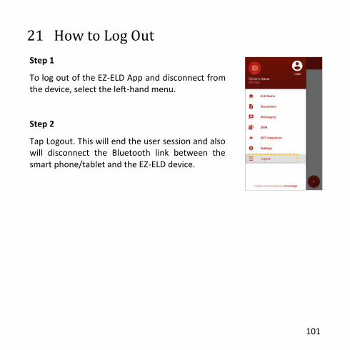
To log out of the EZ-ELD App and disconnect from the device, select the left-hand menu.
Step 2
Tap Logout. This will end the user session and also will disconnect the Bluetooth link between the smart phone/tablet and the EZ-ELD device.
21 How to Log Out
102
22 Warranty
The Stoneridge EZ-ELD® is covered by a 12 month warranty period from the
date of shipment, to materially conform to our published specifications and be free from material defects.
Please refer to our Terms and Conditions at www.EZ-ELD.com for full details on our Warranty and Returns and Refunds policy.

103
For any queries on the Stoneridge EZ-ELD® please contact Technical Support on:
Tel: +1 (833) 994-3953
Email: [email protected]
151406002 – Rev.4.0
© Stoneridge Aftermarket Inc.
Top Related