


Languages
Pages
Legal

RESIDENTIAL & COMMERCIAL IRRIGATION | Built on Innovation hunterindustries.com
DRIP IRRIGATION DESIGN & INSTALLATION GUIDE
TABLE OF CONTENTS
Introduction
1 About This Technical Guide
1 About Hunter Industries
2 PLD
3 Eco-Wrap
4 Eco-Mat®
5 About Inline and Subsurface Drip
6 Applications
7 Limitations
Design
8 Water Quality
8 Soil Type and Water Movement
10 Components of an Inline Drip System
20 Calculations
Installation
21 Preparation
22 Procedure
Operation and Maintenance
24 Initial Operation
25 Scheduling
26 Maintenance
Appendix A: Example Installation Details
Appendix B: Technical Product Data
28 Coefficient of Variation
28 PLD
28 Eco-Wrap
29 Eco-Mat
29 Fittings
1 Learn more. Visit hunterindustries.com or contact your local sales manager.
INTRODUCTION
The combination of PLD, Eco-Wrap®, and Eco-Mat
provides a comprehensive suite of inline drip irrigation
products for landscape professionals. Together, they are
designed to efficiently irrigate any planted area.
Irrigation’s most basic function is to provide water where
and when it is needed. Irrigation is not provided directly
to plants, but to the root zone of the soil. The root zone
functions as a reservoir and is highly dependent on plant
type, soil type, soil compaction, and other factors.
Traditional irrigation projects water through the air. As
water floods the surface, gravity is used to distribute
water through the root zone. Distribution of water
through the air is dependent on the ability of emission
devices to project water evenly and within the boundaries
of the target area. External factors such as wind and heat
increase evaporation, affect droplet cohesion, pattern
distribution and cutoff, and frequently result in overspray.
The result? Significant water waste.
Hunter’s inline drip products use capillarity to move water
in all directions through the root zone. Water is
distributed with maximum uniformity in all directions,
providing the right amount of water exactly where
needed to stimulate and sustain healthy root growth.
When used below grade, inline drip irrigation significantly
limits the loss of water through evaporation.
Eco-Mat supplements the soil’s ability to provide water
by increasing the carrying capacity through pore space
inherent in the polypropylene fleece mat. This is
especially useful for applications with limited natural
water-carrying capacity such as highly permeable soils
and planting media.
ABOUT THIS TECHNICAL GUIDE
This guide outlines the application, design, and instal-
lation of Hunter’s inline drip products that provide
designers, installers, and irrigation managers a new class
of irrigation technology. It is written for professionals
who have a solid understanding of basic irrigation and
design practices. Technical information for the specifica-
tion, design, installation, and operation of Hunter inline
drip products, including PLD (Professional Landscape
Dripline), Eco-Wrap, and Eco-Mat, are included.
Information is organized sequentially; moving front to
back in the order you’ll need it most. Under each topic
essential information is placed at the beginning and
becomes progressively more detailed.
ABOUT HUNTER INDUSTRIES
Hunter Industries is a family-owned global company that
provides high quality, efficient solutions for the irrigation,
outdoor lighting, and custom manufacturing industries.
Headquartered in San Marcos, California since 1981,
Hunter is a market leader in producing and marketing a
full range of water-efficient, easy-to-use irrigation solu-
tions for residential, commercial, and golf course applica-
tions. Designed with the demands of irrigation profes-
sionals in mind, the current Hunter irrigation product line
includes pop-up gear-driven rotors, high-efficiency rotary
nozzles, spray sprinklers, valves, controllers, central
controllers, professional landscape drip and inline drip
products, and weather sensors.
2 Website hunterindustries.com | Customer Support 760-744-5240 | Technical Service 760-591-7383
PROFESSIONAL LANDSCAPE DRIPLINE
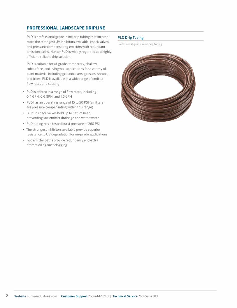
PLD is professional grade inline drip tubing that incorpo-
rates the strongest UV inhibitors available, check valves,
and pressure-compensating emitters with redundant
emission paths. Hunter PLD is widely regarded as a highly
efficient, reliable drip solution.
PLD is suitable for at-grade, temporary, shallow
subsurface, and living wall applications for a variety of
plant material including groundcovers, grasses, shrubs,
and trees. PLD is available in a wide range of emitter
flow rates and spacing.
PLD Drip Tubing
Professional-grade inline drip tubing
• PLD is offered in a range of flow rates, including 0.4 GPH, 0.6 GPH, and 1.0 GPH
• PLD has an operating range of 15 to 50 PSI (emitters are pressure compensating within this range)
• Built-in check valves hold up to 5 ft. of head, preventing low emitter drainage and water waste
• PLD tubing has a tested burst pressure of 260 PSI
• The strongest inhibitors available provide superior resistance to UV degradation for on-grade applications
• Two emitter paths provide redundancy and extra protection against clogging

3 Learn more. Visit hunterindustries.com or contact your local sales manager.
ECO-WRAP
Eco-Wrap is PLD encased in polypropylene fleece. The
polypropylene wrap addresses two issues with other
subsurface irrigation systems: root intrusion and poor
capillary action of the soil. Eco-Wrap overcomes these
challenges and provides significant advantages over
typical inline drip tubing without the use of chemicals or
harmful metal residue, while accelerating lateral water
movement and greatly increasing emission area and
uniformity.
Eco-Wrap is recommended for all subsurface applications
for all types of plant material. Where freely draining soils
or planting media are anticipated, Hunter recommends
Eco-Mat.
• Hunter Professional Landscape Dripline includes check valves and pressure compensating emitters at 0.6 GPH at 12" spacing
• Emitters saturate the fleece wrapping, which speeds lateral movement and distribution throughout the root zone
• Capillary action wicks water through the fleece and into the soil in a widely distributed manner, reducing the potential for tunneling or water waste due to gravity
• Unlike other products, the polypropylene fleece wrap provides protection from root intrusion without using toxic chemicals, metal byproducts, or any other products with a limited lifespan

4 Website hunterindustries.com | Customer Support 760-744-5240 | Technical Service 760-591-7383
ECO-MAT®
Eco-Mat uses a unique combination of specialized PLD
and polypropylene fleece, which evenly disperses water
throughout the target area. Eco-Mat also supplements
the water holding capacity of the soil. Each square yard
holds approximately one half gallon of water, available
directly to the root zone of the plant material. This is
especially useful in turf and applications that use rapidly
draining planting media such as rooftop gardens.
Eco-Mat is recommended for subsurface applications
in traditional planters, intensive and extensive rooftop
gardens for turf and sod-forming plant types, and shrubs
and smaller plants with root zones generally 12" or less.
Eco-Mat is ideal for completely uniform distribution, and
particularly suited for freely draining soils and engineered
growing media.
• Special engineered polypropylene fleece fabric mat, provides distribution to nearly 100% of the irrigated area
• Fleece mat supplements the soil’s natural water holding capacity
• Uses Hunter Professional Landscape Dripline with check valves and pressure compensating emitters at 0.6 GPH at 12" spacing
• Emitters saturate the wrapped tubing and then the Eco-Mat with water. Once saturated, Eco-Mat provides water to the entire landscaped area through capillary action
• Unlike any other product, Eco-Mat provides nearly 100% distribution uniformity by using dispersed emis-sion throughout the entire irrigated area
LEED Water Efficiency (written from standpoint of LEED 2012)Hunter products contribute significantly to LEED BD+C Water Efficiency (WE) Credits. Beginning in 2012, LEED BD+C uses the US EPA’s WaterSense Water Budget Tool instead of local requirements to calculate a project’s water use baseline. Savings of 50% or more beyond the baseline provide an additional credit. Water savings can be achieved using PLD, Eco-Wrap, or Eco-Mat to irrigate all types of plant material that require a subsurface solution. Since its distribution uniformity approaches 100%, Eco-Mat will provide the highest degree of savings. Total water savings can be enhanced by using one of Hunter’s weather sensors such as Solar Sync or ET System.
The Sustainable Sites InitiativeThe Sustainable Sites Initiative (2009) uses the same baseline approach as LEED 2012 to calculate irrigation water use. Hunter products provide significant water savings to achieve prerequisite 3.1 and to potentially achieve credit 3.2. Hunter drip irrigation and other products, such as ET-based controllers and MP Rotators, provide significantly higher efficiencies than the baseline calculation assumes.
Discussion of California MWELO (AB 1881) In 2010, California instituted a statewide requirement known as the Model Water Efficient Landscape Ordinance. This ordinance restricts the volume of applied water allowed, and with few exceptions, prohibits overhead irrigation within 24" of hardscape, or shrub areas. Many more states are monitoring the effectiveness of this ordinance in reducing overspray and runoff and may follow suit. PLD, Eco-Wrap, and Eco-Mat provide the ideal irrigation solution for these areas.
SPECIAL POLYPROPYLENE FLEECE
SEAM: polypropylene thread
DRIPLINE COVER: Special polypropylene �eece
PLD DRIPLINE
5 Learn more. Visit hunterindustries.com or contact your local sales manager.
ABOUT INLINE AND SUBSURFACE DRIP
Inline drip is ideal for all types of planted areas, including
specialized sports applications, parks, streetscapes,
commercial, and residential landscapes. Installing the
emission system under the surface reduces or eliminates
damage from heavy traffic, vandalism, ultraviolet degra-
dation, and impact.
Other types of irrigation systems require an exact
pressure to maintain their pattern and distribution. As
pressures change, the performance of these systems
degrades substantially. By contrast, inline drip irrigation
allows very high distribution uniformity even at low or
varying pressures.
Inline drip can significantly reduce water waste while
stimulating plant growth by providing the optimum water
content to soil, avoiding “flood and drought” cycles that
cause root dieback, and avoiding anaerobic conditions.
Subsurface applications further reduce water waste
through evaporation.
Drip irrigation is an ideal solution for irregular or small
areas. Inline drip irrigation limits the potential for liability
by reducing or eliminating overspray on buildings,
walkways, roadways, and other trafficked areas. Main-
tenance costs are often lower due to reduced overspray,
runoff, erosion, compaction, water staining, and property
damage. With no exposed emission equipment to get
vandalized, stolen, damaged, misaligned, or worn out,
material costs over the life of a project are substantially
lower.
A fertilizer injection (fertigation) system—for chemical or
organic products—can be easily introduced to inline drip
systems and distributed directly to plant root zones. This
avoids human and animal contact and provides a more
even distribution of material, minimizing material cost.
An injection system also provides the ability to maintain
inline drip tubing by controlling mineral or biological
buildup by periodically injecting mild acid or trace
amounts of chlorine.
Where water supply or irrigation scheduling is problem-
atic, subsurface irrigation may be used to extend the
watering window. Irrigation can be scheduled anytime,
even during active use, without worry about increased
evaporation during the day. Extending the watering
window may allow lower flows, resulting in significant sav-
ings through reduced connection fees and materials costs.
All Hunter inline drip products feature a specially
engineered emitter that includes:
Inline Emitter
Features dual turbulent flow paths that promote scouring to prevent clogging from debris and dissolved minerals
24 Hour Advance Watering
8 hoursoverhead irrigation
Up to 24 hoursdrip irrigation
• Dual turbulent flow paths that promote scouring to prevent clogging from debris and dissolved minerals
• Built-in check valve preventing low-emitter drainage, retaining up to 5 ft. of water
• Pressure compensation across a wide range of pressure, from 15-50 PSI
• Robust construction preventing crushing or internal emitter damage even under heavy use
6 Website hunterindustries.com | Customer Support 760-744-5240 | Technical Service 760-591-7383
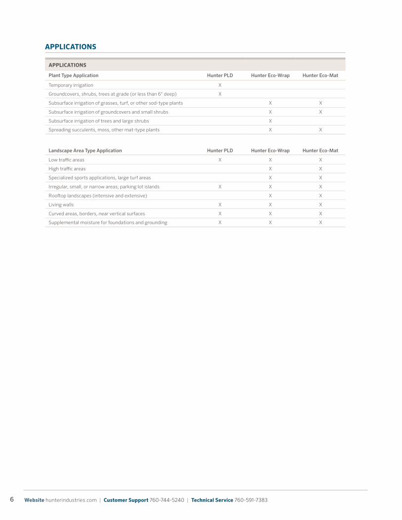
APPLICATIONS
Plant Type Application Hunter PLD Hunter Eco-Wrap Hunter Eco-Mat
Temporary irrigation X
Groundcovers, shrubs, trees at grade (or less than 6" deep) X
Subsurface irrigation of grasses, turf, or other sod-type plants X X
Subsurface irrigation of groundcovers and small shrubs X X
Subsurface irrigation of trees and large shrubs X
Spreading succulents, moss, other mat-type plants X X
Landscape Area Type Application Hunter PLD Hunter Eco-Wrap Hunter Eco-Mat
Low traffic areas X X X
High traffic areas X X
Specialized sports applications, large turf areas X X
Irregular, small, or narrow areas; parking lot islands X X X
Rooftop landscapes (intensive and extensive) X X
Living walls X X X
Curved areas, borders, near vertical surfaces X X X
Supplemental moisture for foundations and grounding X X X
APPLICATIONS
7 Learn more. Visit hunterindustries.com or contact your local sales manager.
Rooftop Landscapes
Eco-Wrap and Eco-Mat are particularly suited for rooftop
and other on-deck applications. Whether intensive
or extensive, these applications typically use a freely
draining lightweight planting media. Because this media
has large particle size and pore volume, the capillarity
of this media can be greatly reduced when compared
to topsoil. Other irrigation systems quickly exceed the
media’s ability to move water via capillary action. Gravity
takes over, moving water rapidly down through the media
and into the drainage layer, resulting in water waste. Eco-
Wrap and Eco-Mat widely distribute the point of emission,
mitigating this problem.
Living Walls
PLD, Eco-Wrap, and Eco-Mat are ideal for irrigating living
walls. Typically comprised of planted pockets supported
and separated by fabric or other structure, these applica-
tions face the same challenges as rooftop landscapes. It’s
necessary to ensure that emitters are evenly spaced in
the planted pockets by matching the inline spacing to the
planted structure, or by splicing as required. When using
Eco-Wrap or Eco-Mat with separated planting pockets,
cut the fleece between the pockets to prevent wicking
outside each cell. When using Eco-Mat, fold the fleece
blanket to conform to the perimeter of each cell, maxi-
mizing contact with the planting media. Eco-Mat supple-
ments the media’s holding capacity, providing an extra
reservoir of water.
Retaining Walls
Inline drip irrigation is ideal for all types of retaining walls,
including walls with planted pockets, or just planted areas
at the top or base of the wall. Its compact form allows
irrigation even in the tightest of plant pockets. Inline drip
prevents overspray and limits runoff, preventing damage
to walls and limiting liability.
Retrofitting Existing Systems
PLD is ideal for surface application in existing shrub and
groundcover areas where minimal disturbance is required.
Adaptors easily convert existing sprinkler risers to 17 mm
insert fittings for use with inline drip tubing. In turf areas
Eco-Wrap can be trenched and backfilled. Where turf
areas are being installed or replaced, consider Eco-Mat as
a water-saving alternative to traditional irrigation systems.
Specialized Sports Applications
Inline subsurface drip provides a non-intrusive way to
irrigate turf athletic fields while avoiding the compaction
problems that plague traditional systems. Compaction
is exacerbated by heavy use in saturated conditions and
seriously affects playability and turf grass health. The use
of capillary action to distribute water laterally (instead
of overhead irrigation and gravity) avoids the flood and
soak cycle that damages fields. Subsurface irrigation
protects equipment from impact and sunlight, protects
players from tripping, avoids impact hazards, and reduces
maintenance and/or replacement.
LIMITATIONS
Subsurface irrigation has significant differences when
compared to overhead irrigation. Maintenance practices
must be scheduled regularly and are proactive, rather
than reactive. Under certain conditions, supplemental
irrigation may be required to:
Subsurface PLD applications should be reviewed for root
intrusion potential, and should not be used at depths
greater than 6". For all subsurface applications under
turf, Hunter recommends Eco-Wrap or Eco-Mat.
• Grow in sod and other plants until they adapt to the subsurface irrigation system
• Wash salt, dirt, smog, or other deleterious material off foliage
• Water in granular and other topically applied fertilizers
• Sufficiently wet broadcast seed to assure even germination
8 Website hunterindustries.com | Customer Support 760-744-5240 | Technical Service 760-591-7383
DESIGN
Prior to designing a system, collect the following information:
WATER QUALITY
Water quality can significantly affect the operation and
longevity of inline drip irrigation systems. Below are
general parameters that can be identified by a water
quality test. Values less than or equal to the low column
are ideal for inline drip irrigation.
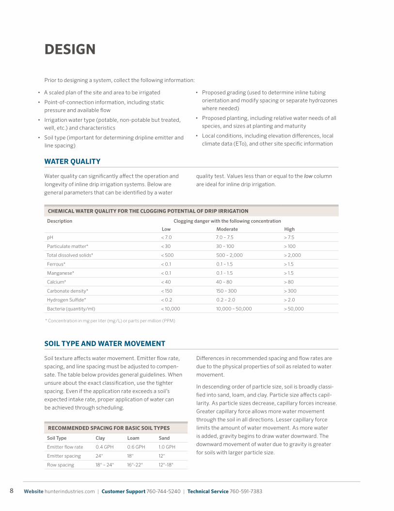
CHEMICAL WATER QUALITY FOR THE CLOGGING POTENTIAL OF DRIP IRRIGATION
Description Clogging danger with the following concentration
Low Moderate High
pH < 7.0 7.0 – 7.5 > 7.5
Particulate matter* < 30 30 – 100 > 100
Total dissolved solids* < 500 500 – 2,000 > 2,000
Ferrous* < 0.1 0.1 – 1.5 > 1.5
Manganese* < 0.1 0.1 – 1.5 > 1.5
Calcium* < 40 40 – 80 > 80
Carbonate density* < 150 150 – 300 > 300
Hydrogen Sulfide* < 0.2 0.2 – 2.0 > 2.0
Bacteria (quantity/ml) < 10,000 10,000 – 50,000 > 50,000
* Concentration in mg per liter (mg/L) or parts per million (PPM)
SOIL TYPE AND WATER MOVEMENT
Soil texture affects water movement. Emitter flow rate,
spacing, and line spacing must be adjusted to compen-
sate. The table below provides general guidelines. When
unsure about the exact classification, use the tighter
spacing. Even if the application rate exceeds a soil’s
expected intake rate, proper application of water can
be achieved through scheduling.
RECOMMENDED SPACING FOR BASIC SOIL TYPES
Soil Type Clay Loam Sand
Emitter flow rate 0.4 GPH 0.6 GPH 1.0 GPH
Emitter spacing 24" 18" 12"
Row spacing 18" – 24" 16"-22" 12"-18"
Differences in recommended spacing and flow rates are
due to the physical properties of soil as related to water
movement.
In descending order of particle size, soil is broadly classi-
fied into sand, loam, and clay. Particle size affects capil-
larity. As particle sizes decrease, capillary forces increase.
Greater capillary force allows more water movement
through the soil in all directions. Lesser capillary force
limits the amount of water movement. As more water
is added, gravity begins to draw water downward. The
downward movement of water due to gravity is greater
for soils with larger particle size.
• A scaled plan of the site and area to be irrigated
• Point-of-connection information, including static pressure and available flow
• Irrigation water type (potable, non-potable but treated, well, etc.) and characteristics
• Soil type (important for determining dripline emitter and line spacing)
• Proposed grading (used to determine inline tubing orientation and modify spacing or separate hydrozones where needed)
• Proposed planting, including relative water needs of all species, and sizes at planting and maturity
• Local conditions, including elevation differences, local climate data (ETo), and other site specific information
9 Learn more. Visit hunterindustries.com or contact your local sales manager.
For soils with smaller particle size, emitters can be
spaced farther apart because capillary force will draw
water farther before gravity pulls it down. For soils with
large particle size, water will almost immediately begin
moving downward. Emitters must be spaced closer
together to spread the water through lesser capillary
action before it is lost below the root zone due to gravity.
Use the following table as a guideline for spacing: If you
are unsure of the exact soil type, or know that soils will
differ on a site, use the minimum recommended spacing
and the maximum recommended flow rate to ensure that
water is evenly distributed.
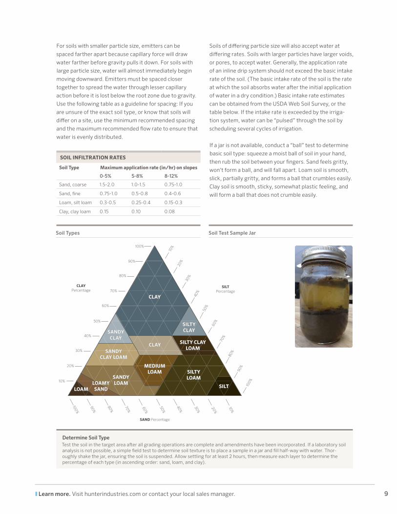
SOIL INFILTRATION RATES
Soil Type Maximum application rate (in/hr) on slopes
0-5% 5-8% 8-12%
Sand, coarse 1.5-2.0 1.0-1.5 0.75-1.0
Sand, fine 0.75-1.0 0.5-0.8 0.4-0.6
Loam, silt loam 0.3-0.5 0.25-0.4 0.15-0.3
Clay, clay loam 0.15 0.10 0.08
Soils of differing particle size will also accept water at
differing rates. Soils with larger particles have larger voids,
or pores, to accept water. Generally, the application rate
of an inline drip system should not exceed the basic intake
rate of the soil. (The basic intake rate of the soil is the rate
at which the soil absorbs water after the initial application
of water in a dry condition.) Basic intake rate estimates
can be obtained from the USDA Web Soil Survey, or the
table below. If the intake rate is exceeded by the irriga-
tion system, water can be “pulsed” through the soil by
scheduling several cycles of irrigation.
If a jar is not available, conduct a “ball” test to determine
basic soil type: squeeze a moist ball of soil in your hand,
then rub the soil between your fingers. Sand feels gritty,
won’t form a ball, and will fall apart. Loam soil is smooth,
slick, partially gritty, and forms a ball that crumbles easily.
Clay soil is smooth, sticky, somewhat plastic feeling, and
will form a ball that does not crumble easily.
CLAYCLAY
SANDYCLAY
SANDYCLAY
CLAYCLAY
SILTYCLAYSILTYCLAY
SILTY CLAY LOAM
SILTY CLAY LOAM
MEDIUM LOAM
MEDIUM LOAM SILTY
LOAMSILTY LOAM
SILTSILT
SANDY CLAY LOAM
SANDY CLAY LOAM
SANDY LOAM
SANDY LOAMLOAMY
SANDLOAMY SANDLOAMLOAM
10%
30%
20%
40%
50%
60%
70%
80%
90%
100%
100%
80%
90%
70%
60%
50%
40%
30%
20%
10%
10%
30%
20%
40%
50%
60%
70%
80%
90%
100%
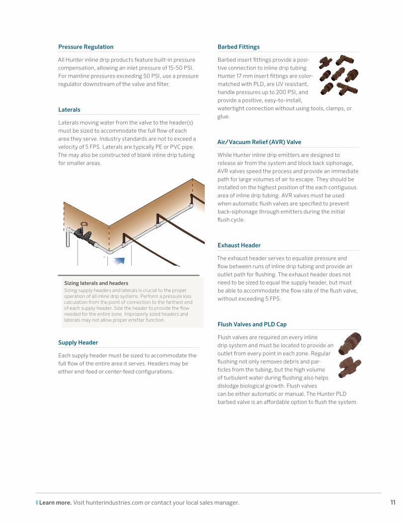
SILTPercentage
SAND Percentage
CLAYPercentage
Determine Soil TypeTest the soil in the target area after all grading operations are complete and amendments have been incorporated. If a laboratory soil analysis is not possible, a simple field test to determine soil texture is to place a sample in a jar and fill half-way with water. Thor-oughly shake the jar, ensuring the soil is suspended. Allow settling for at least 2 hours, then measure each layer to determine the percentage of each type (in ascending order: sand, loam, and clay).
Soil Test Sample JarSoil Types

10 Website hunterindustries.com | Customer Support 760-744-5240 | Technical Service 760-591-7383
COMPONENTS OF AN INLINE DRIP SYSTEM
This section addresses design considerations for each component of an inline drip system, moving from the valve
downstream to the flushing device. For more information about other irrigation components,
see http://www.hunterindustries.com.
Controller
A controller is the “brain” of every irrigation system. Hunter controllers provide effective tools for irrigation management. For projects larger than 30 zones, Hunter recommends the use of two-wire decoder technology, available for both ACC and I-Core controllers. For areas without AC power, Hunter’s wall mount or in-valve-box battery controllers are ideal. All controllers are compatible with PLD, Eco-Wrap, and Eco-Mat®.
ET-Sensor
ET-based controllers optimize scheduling based on real-time weather conditions to minimize water waste due to management factors. Hunter’s Solar Sync ET sensor adds even more efficiency to inline drip project by automati-cally adjusting irrigation scheduling for changing weather and site-specific climate conditions. The Solar Sync is compatible with all AC operated Hunter controllers. Both installation and operation are simple processes.
Zone Control Kit
Every successful inline drip irrigation zone starts with three items: zone control, filtration, and pressure regula-tion. Hunter’s Drip Zone Control Kit combine all three into one factory-assembled, water-tested kit, which speeds up specification and installation. For more options, each component can be individually specified.
Valve
A remote control valve is typically used to automatically activate inline drip systems. Alternatively, a manual valve or even hose bib may be used for non-automatic systems. Each hydrozone should be irrigated by a separate valve. Hydrozones are areas with specific conditions that affect irrigation, including plant type, spacing, density, microcli-mate, exposure, and slope.
Follow all local requirements to prevent backflow and back siphonage.
Filter
Filtration must be provided for all inline drip systems, regardless of water supply type. Even potable water contains suspended particulates which may clog inline emitters. Filters also help reduce biological contaminants.
For large or distributed systems, consider a disk filter near the point of connection. This provides a single, easily maintained item in an accessible location. Use screen fil-ters at each drip valve as a secondary level of protection in case any debris enters the irrigation system downstream of the primary filter.
Use a filter with a minimum filtration level of 120 microns (approximately 120 mesh, or 0.125 mm).
Inline Drip Tubing
Inline drip tubing consists of tubing laid in parallel rows. This creates a grid of emitters evenly spaced throughout the entire irrigated area.
11 Learn more. Visit hunterindustries.com or contact your local sales manager.
Pressure Regulation
All Hunter inline drip products feature built-in pressure compensation, allowing an inlet pressure of 15-50 PSI. For mainline pressures exceeding 50 PSI, use a pressure regulator downstream of the valve and filter.
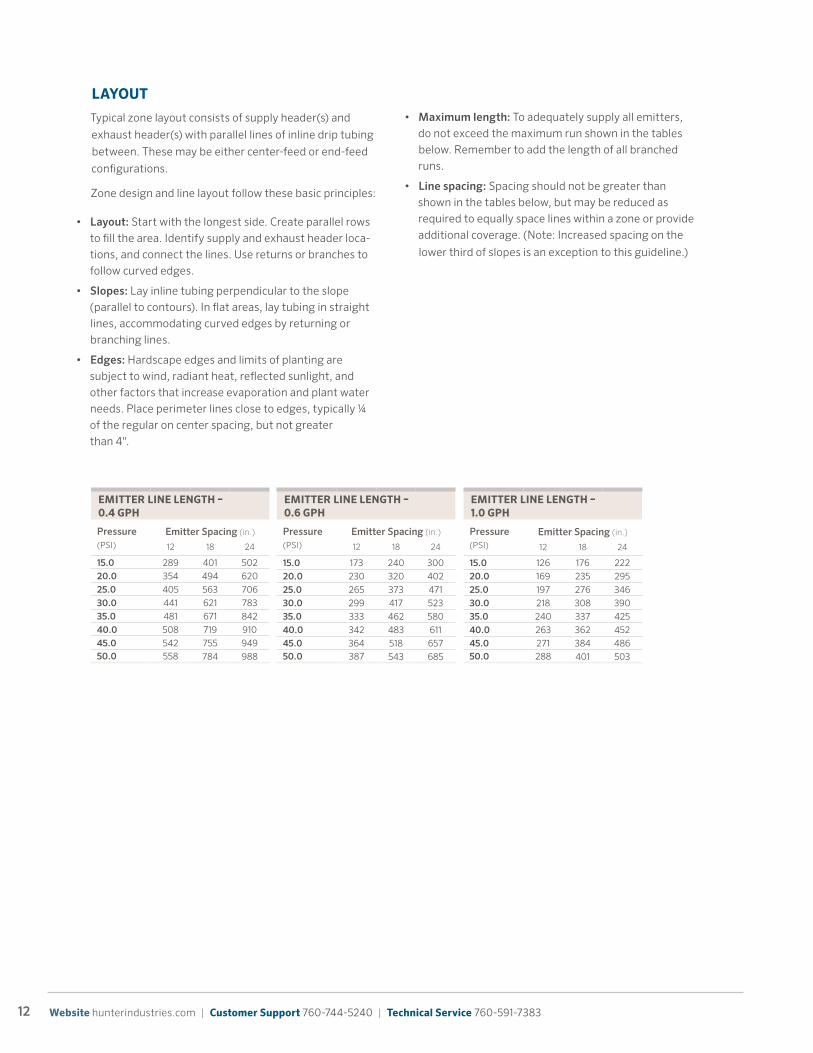
Laterals
Laterals moving water from the valve to the header(s) must be sized to accommodate the full flow of each area they serve. Industry standards are not to exceed a velocity of 5 FPS. Laterals are typically PE or PVC pipe. The may also be constructed of blank inline drip tubing for smaller areas.
Sizing laterals and headers Sizing supply headers and laterals is crucial to the proper operation of all inline drip systems. Perform a pressure loss calculation from the point of connection to the farthest end of each supply header. Size the header to provide the flow needed for the entire zone. Improperly sized headers and laterals may not allow proper emitter function.
Supply Header
Each supply header must be sized to accommodate the full flow of the entire area it serves. Headers may be either end-feed or center-feed configurations.
Barbed Fittings
Barbed insert fittings provide a posi-tive connection to inline drip tubing. Hunter 17 mm insert fittings are color-matched with PLD, are UV resistant, handle pressures up to 200 PSI, and provide a positive, easy-to-install, watertight connection without using tools, clamps, or glue.
Air/Vacuum Relief (AVR) Valve
While Hunter inline drip emitters are designed to release air from the system and block back siphonage, AVR valves speed the process and provide an immediate path for large volumes of air to escape. They should be installed on the highest position of the each contiguous area of inline drip tubing. AVR valves must be used when automatic flush valves are specified to prevent back-siphonage through emitters during the initial flush cycle.
Exhaust Header
The exhaust header serves to equalize pressure and flow between runs of inline drip tubing and provide an outlet path for flushing. The exhaust header does not need to be sized to equal the supply header, but must be able to accommodate the flow rate of the flush valve, without exceeding 5 FPS.
Flush Valves and PLD Cap
Flush valves are required on every inline drip system and must be located to provide an outlet from every point in each zone. Regular flushing not only removes debris and par-ticles from the tubing, but the high volume of turbulent water during flushing also helps dislodge biological growth. Flush valves can be either automatic or manual. The Hunter PLD barbed valve is an affordable option to flush the system.
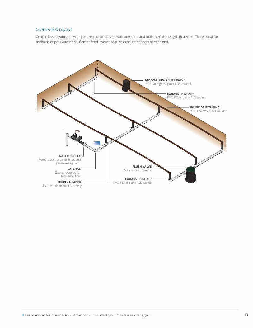
FLUSH VALVEManual or automatic
EXHAUST HEADERPVC, PE, or blank
PLD tubing
SUPPLY HEADERPVC, PE, or blank PLD tubing
WATER SUPPLYRemote control valve, �lter, and pressure regulator
LATERALSize as required for total zone �ow
AIR/VACUUM RELIEF VALVEInstall at highest point of each area
INLINE DRIP TUBINGPLD, Eco-Wrap, or Eco-Mat
12 Website hunterindustries.com | Customer Support 760-744-5240 | Technical Service 760-591-7383
LAYOUT
Typical zone layout consists of supply header(s) and
exhaust header(s) with parallel lines of inline drip tubing
between. These may be either center-feed or end-feed
configurations.
Zone design and line layout follow these basic principles:
• Maximum length: To adequately supply all emitters, do not exceed the maximum run shown in the tables below. Remember to add the length of all branched runs.
• Line spacing: Spacing should not be greater than shown in the tables below, but may be reduced as required to equally space lines within a zone or provide additional coverage. (Note: Increased spacing on the
lower third of slopes is an exception to this guideline.)EMITTER FLOW RATE – 1.0 GPH
Row Spacing (in.)
Emitter Spacing (in.)
12 18 24
12 1.60 1.07 0.80
14 1.38 0.92 0.69
16 1.20 0.80 0.60
18 1.07 0.71 0.53
20 0.96 0.64 0.4824 0.80 0.53 0.40
NotesApplication rates in inches per hour
EMITTER LINE LENGTH – 0.4 GPH
Pressure(PSI)
Emitter Spacing (in.)
12 18 24
15.0 289 401 502
20.0 354 494 620
25.0 405 563 706
30.0 441 621 783
35.0 481 671 842
40.0 508 719 910
45.0 542 755 94950.0 558 784 988
EMITTER LINE LENGTH – 0.6 GPH
Pressure(PSI)
Emitter Spacing (in.)
12 18 24
15.0 173 240 300
20.0 230 320 402
25.0 265 373 471
30.0 299 417 523
35.0 333 462 580
40.0 342 483 611
45.0 364 518 65750.0 387 543 685
EMITTER LINE LENGTH – 1.0 GPH
Pressure(PSI)
Emitter Spacing (in.)
12 18 24
15.0 126 176 222
20.0 169 235 295
25.0 197 276 346
30.0 218 308 390
35.0 240 337 425
40.0 263 362 452
45.0 271 384 48650.0 288 401 503
EMITTER FLOW RATE – 0.6 GPH
Row Spacing (in.)
Emitter Spacing (in.)
12 18 24
12 0.96 0.64 0.48
14 0.83 0.55 0.41
16 0.72 0.48 0.36
18 0.64 0.43 0.32
20 0.58 0.39 0.2924 0.48 0.32 0.24
EMITTER FLOW RATE – 0.4 GPH
Row Spacing (in.)
Emitter Spacing (in.)
12 18 24
12 0.64 0.43 0.32
14 0.55 0.37 0.28
16 0.48 0.32 0.24
18 0.43 0.29 0.21
20 0.39 0.26 0.1924 0.32 0.21 0.16
PLD EMITTER LINE MAXIMUM LENGTH CHARTS
PLD APPLICATION RATES
QUICK REFERENCE CHART – GPM PER 100'
Emitter(GPH)
Emitter Spacing (in.)
12 18 24
0.4 0.67 0.44 0.33
0.6 1.00 0.67 0.501.0 1.67 1.11 0.83
PLD FLOW CONVERSION CHARTS
• Layout: Start with the longest side. Create parallel rows to fill the area. Identify supply and exhaust header loca-tions, and connect the lines. Use returns or branches to follow curved edges.
• Slopes: Lay inline tubing perpendicular to the slope (parallel to contours). In flat areas, lay tubing in straight lines, accommodating curved edges by returning or branching lines.
• Edges: Hardscape edges and limits of planting are subject to wind, radiant heat, reflected sunlight, and other factors that increase evaporation and plant water needs. Place perimeter lines close to edges, typically ¼ of the regular on center spacing, but not greater than 4".
13 Learn more. Visit hunterindustries.com or contact your local sales manager.
Center-Feed Layout
Center-feed layouts allow larger areas to be served with one zone and maximize the length of a zone. This is ideal for
medians or parkway strips. Center-feed layouts require exhaust headers at each end.
SUPPLY HEADERPVC, PE, or blank PLD tubing
WATER SUPPLYRemote control valve, �lter, and
pressure regulator
LATERALSize as required for
total zone �ow
INLINE DRIP TUBINGPLD, Eco-Wrap, or Eco-Mat
FLUSH VALVEManual or automatic
EXHAUST HEADERPVC, PE, or blank PLD tubing
EXHAUST HEADERPVC, PE, or blank PLD tubing
AIR/VACUUM RELIEF VALVEInstall at highest point of each area
14 Website hunterindustries.com | Customer Support 760-744-5240 | Technical Service 760-591-7383
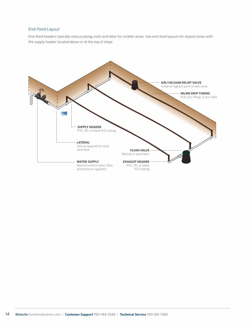
End-Feed Layout
End-feed headers typically reduce piping costs and labor for smaller areas. Use end-feed layouts for sloped zones with
the supply header located above or at the top of slope.
FLUSH VALVEManual or automatic
EXHAUST HEADERPVC, PE, or blank
PLD tubing
SUPPLY HEADERPVC, PE, or blank PLD tubing
WATER SUPPLYRemote control valve, �lter, and pressure regulator
LATERALSize as required for total zone �ow
AIR/VACUUM RELIEF VALVEInstall at highest point of each area
INLINE DRIP TUBINGPLD, Eco-Wrap, or Eco-Mat
15 Learn more. Visit hunterindustries.com or contact your local sales manager.
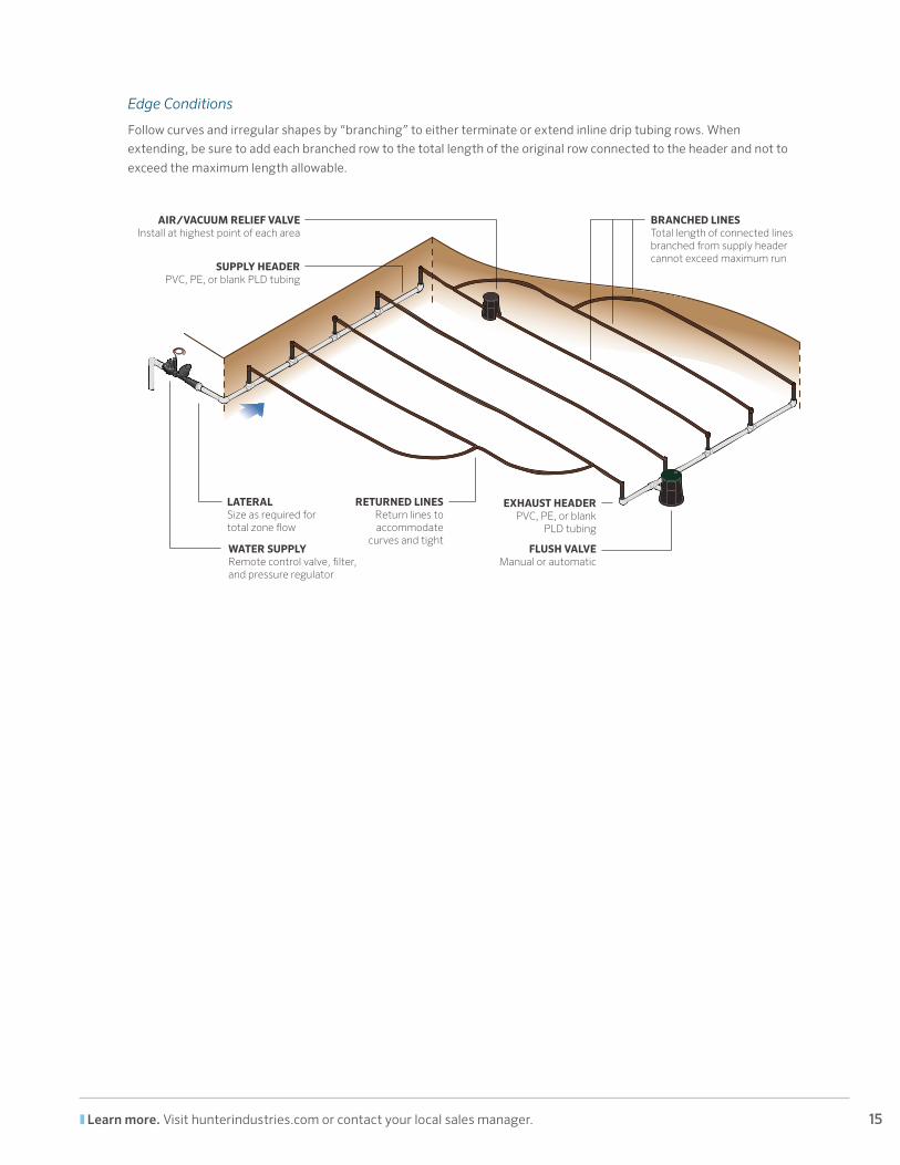
Edge Conditions
Follow curves and irregular shapes by “branching” to either terminate or extend inline drip tubing rows. When
extending, be sure to add each branched row to the total length of the original row connected to the header and not to
exceed the maximum length allowable.
WATER SUPPLYRemote control valve, �lter, and pressure regulator
LATERALSize as required for total zone �ow
AIR/VACUUM RELIEF VALVEInstall at highest point of each area
BRANCHED LINESTotal length of connected lines branched from supply header cannot exceed maximum run
FLUSH VALVEManual or automatic
EXHAUST HEADERPVC, PE, or blank
PLD tubing
SUPPLY HEADERPVC, PE, or blank PLD tubing
RETURNED LINESReturn lines to accommodate
curves and tight
16 Website hunterindustries.com | Customer Support 760-744-5240 | Technical Service 760-591-7383
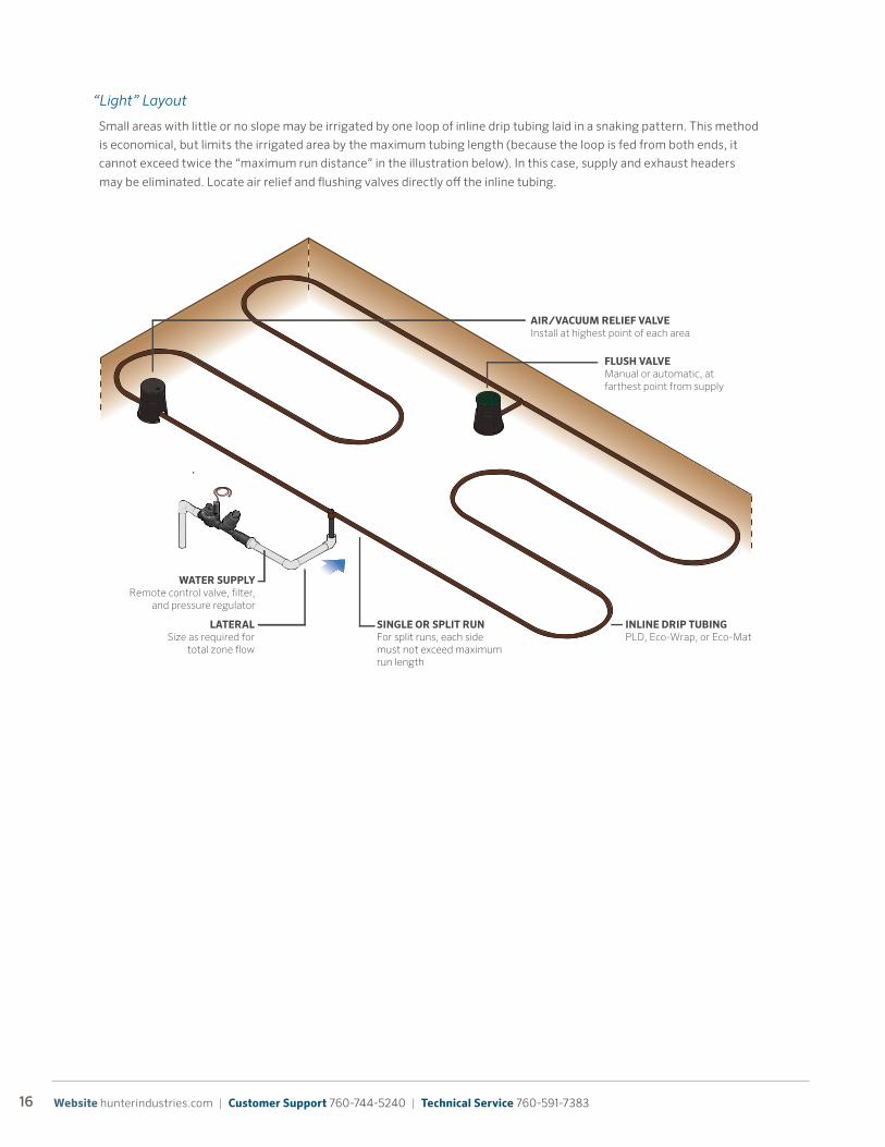
“Light” Layout
Small areas with little or no slope may be irrigated by one loop of inline drip tubing laid in a snaking pattern. This method
is economical, but limits the irrigated area by the maximum tubing length (because the loop is fed from both ends, it
cannot exceed twice the “maximum run distance” in the illustration below). In this case, supply and exhaust headers
may be eliminated. Locate air relief and flushing valves directly off the inline tubing.
WATER SUPPLYRemote control valve, �lter,
and pressure regulator
LATERALSize as required for
total zone �ow
AIR/VACUUM RELIEF VALVEInstall at highest point of each area
INLINE DRIP TUBINGPLD, Eco-Wrap, or Eco-Mat
FLUSH VALVEManual or automatic, at farthest point from supply
SINGLE OR SPLIT RUNFor split runs, each side must not exceed maximum run length
17 Learn more. Visit hunterindustries.com or contact your local sales manager.
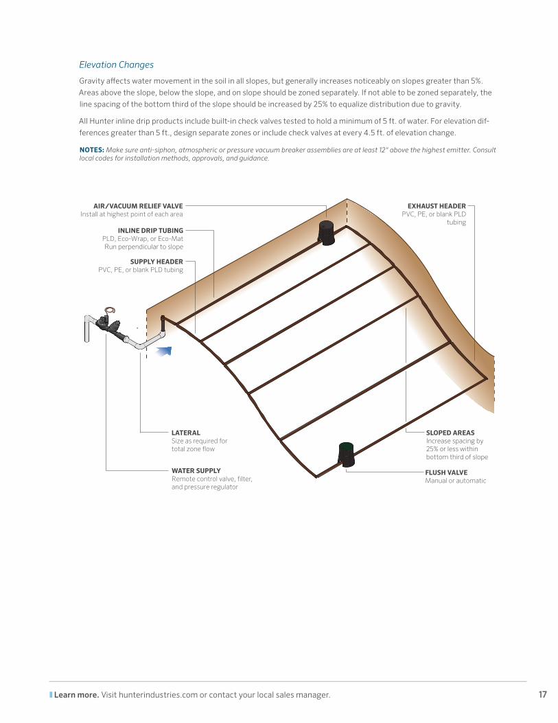
Elevation Changes
Gravity affects water movement in the soil in all slopes, but generally increases noticeably on slopes greater than 5%.
Areas above the slope, below the slope, and on slope should be zoned separately. If not able to be zoned separately, the
line spacing of the bottom third of the slope should be increased by 25% to equalize distribution due to gravity.
All Hunter inline drip products include built-in check valves tested to hold a minimum of 5 ft. of water. For elevation dif-
ferences greater than 5 ft., design separate zones or include check valves at every 4.5 ft. of elevation change.
NOTES: Make sure anti-siphon, atmospheric or pressure vacuum breaker assemblies are at least 12" above the highest emitter. Consult local codes for installation methods, approvals, and guidance.
FLUSH VALVEManual or automatic
EXHAUST HEADERPVC, PE, or blank PLD
tubing
SUPPLY HEADERPVC, PE, or blank PLD tubing
WATER SUPPLYRemote control valve, �lter, and pressure regulator
SLOPED AREASIncrease spacing by 25% or less within bottom third of slope
AIR/VACUUM RELIEF VALVEInstall at highest point of each area
INLINE DRIP TUBINGPLD, Eco-Wrap, or Eco-MatRun perpendicular to slope
LATERALSize as required for total zone �ow
18 Website hunterindustries.com | Customer Support 760-744-5240 | Technical Service 760-591-7383
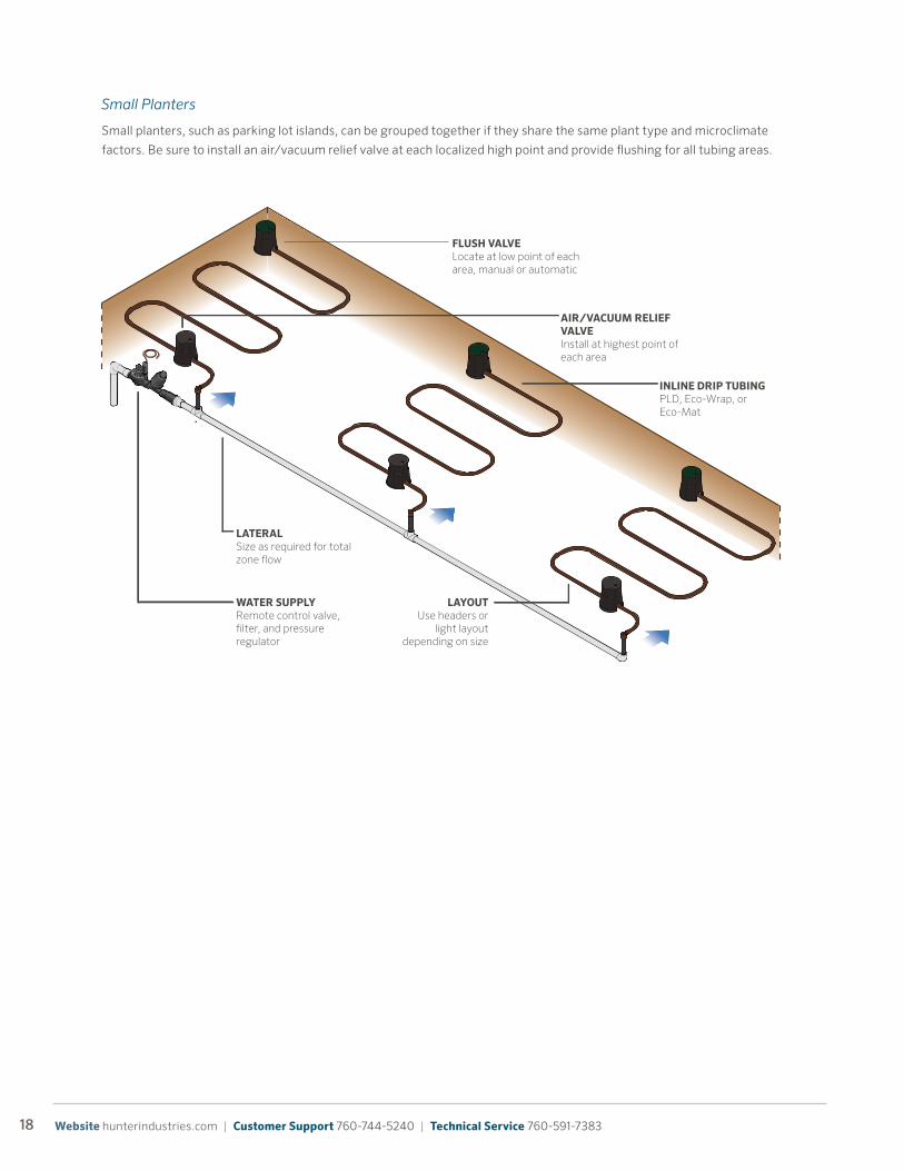
Small Planters
Small planters, such as parking lot islands, can be grouped together if they share the same plant type and microclimate
factors. Be sure to install an air/vacuum relief valve at each localized high point and provide flushing for all tubing areas.
FLUSH VALVELocate at low point of each area, manual or automatic
WATER SUPPLYRemote control valve, �lter, and pressure regulator
LAYOUTUse headers or
light layout depending on size
LATERALSize as required for total zone �ow
AIR/VACUUM RELIEF VALVEInstall at highest point of each area
INLINE DRIP TUBINGPLD, Eco-Wrap, or Eco-Mat
19 Learn more. Visit hunterindustries.com or contact your local sales manager.
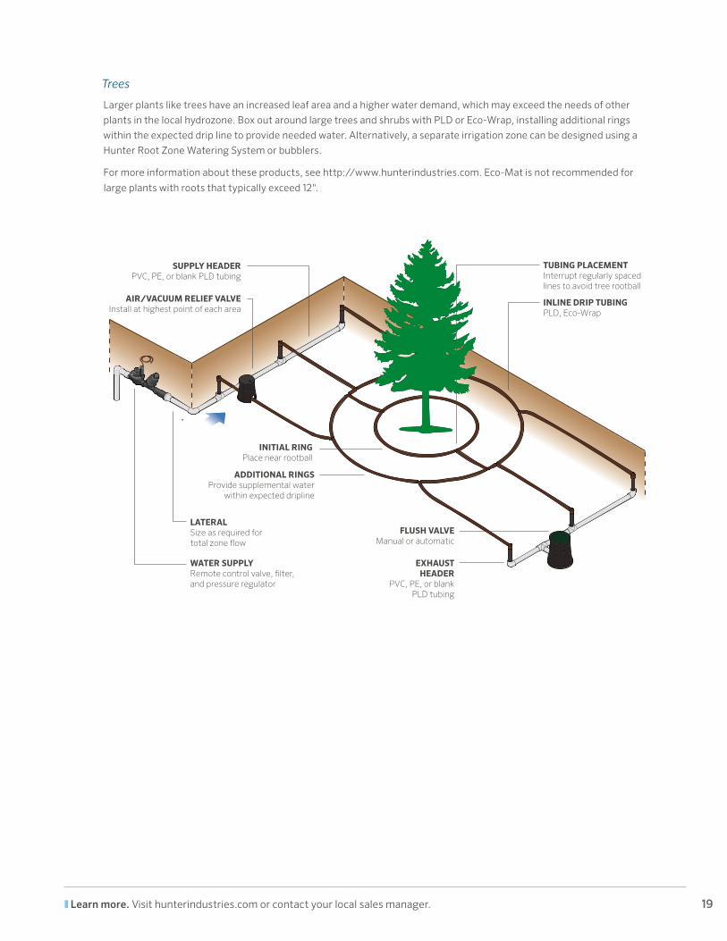
Trees
Larger plants like trees have an increased leaf area and a higher water demand, which may exceed the needs of other
plants in the local hydrozone. Box out around large trees and shrubs with PLD or Eco-Wrap, installing additional rings
within the expected drip line to provide needed water. Alternatively, a separate irrigation zone can be designed using a
Hunter Root Zone Watering System or bubblers.
For more information about these products, see http://www.hunterindustries.com. Eco-Mat is not recommended for
large plants with roots that typically exceed 12".
FLUSH VALVEManual or automatic
EXHAUST HEADER
PVC, PE, or blank PLD tubing
INITIAL RINGPlace near rootball
ADDITIONAL RINGSProvide supplemental water
within expected dripline
WATER SUPPLYRemote control valve, �lter, and pressure regulator
LATERALSize as required for total zone �ow
AIR/VACUUM RELIEF VALVEInstall at highest point of each area
SUPPLY HEADERPVC, PE, or blank PLD tubing
INLINE DRIP TUBINGPLD, Eco-Wrap
TUBING PLACEMENTInterrupt regularly spaced lines to avoid tree rootball
20 Website hunterindustries.com | Customer Support 760-744-5240 | Technical Service 760-591-7383
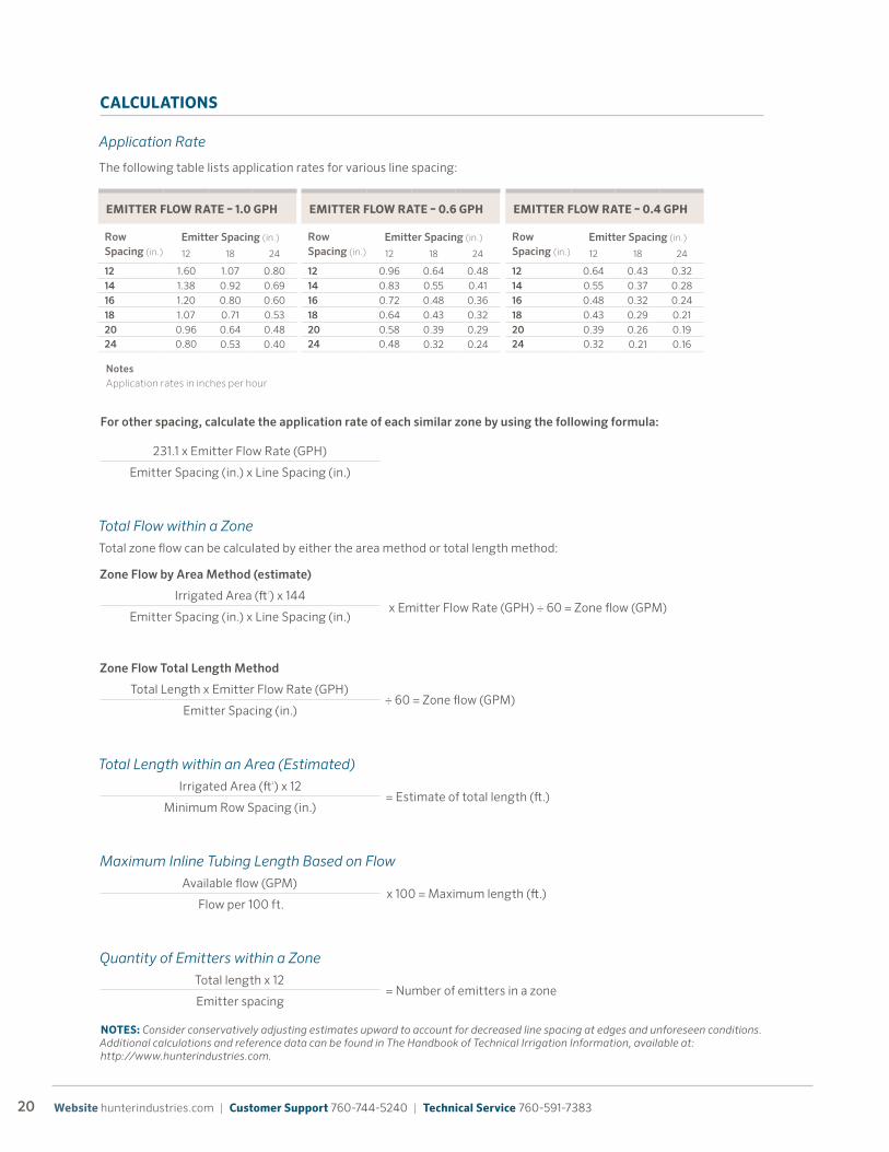
CALCULATIONS
Application Rate
The following table lists application rates for various line spacing:
NOTES: Consider conservatively adjusting estimates upward to account for decreased line spacing at edges and unforeseen conditions. Additional calculations and reference data can be found in The Handbook of Technical Irrigation Information, available at: http://www.hunterindustries.com.
EMITTER FLOW RATE – 1.0 GPH
Row Spacing (in.)
Emitter Spacing (in.)
12 18 24
12 1.60 1.07 0.80
14 1.38 0.92 0.69
16 1.20 0.80 0.60
18 1.07 0.71 0.53
20 0.96 0.64 0.4824 0.80 0.53 0.40
NotesApplication rates in inches per hour
EMITTER LINE LENGTH – 0.4 GPH
Pressure(PSI)
Emitter Spacing (in.)
12 18 24
15.0 289 401 502
20.0 354 494 620
25.0 405 563 706
30.0 441 621 783
35.0 481 671 842
40.0 508 719 910
45.0 542 755 94950.0 558 784 988
EMITTER LINE LENGTH – 0.6 GPH
Pressure(PSI)
Emitter Spacing (in.)
12 18 24
15.0 173 240 300
20.0 230 320 402
25.0 265 373 471
30.0 299 417 523
35.0 333 462 580
40.0 342 483 611
45.0 364 518 65750.0 387 543 685
EMITTER LINE LENGTH – 1.0 GPH
Pressure(PSI)
Emitter Spacing (in.)
12 18 24
15.0 126 176 222
20.0 169 235 295
25.0 197 276 346
30.0 218 308 390
35.0 240 337 425
40.0 263 362 452
45.0 271 384 48650.0 288 401 503
EMITTER FLOW RATE – 0.6 GPH
Row Spacing (in.)
Emitter Spacing (in.)
12 18 24
12 0.96 0.64 0.48
14 0.83 0.55 0.41
16 0.72 0.48 0.36
18 0.64 0.43 0.32
20 0.58 0.39 0.2924 0.48 0.32 0.24
EMITTER FLOW RATE – 0.4 GPH
Row Spacing (in.)
Emitter Spacing (in.)
12 18 24
12 0.64 0.43 0.32
14 0.55 0.37 0.28
16 0.48 0.32 0.24
18 0.43 0.29 0.21
20 0.39 0.26 0.1924 0.32 0.21 0.16
PLD EMITTER LINE MAXIMUM LENGTH CHARTS
PLD APPLICATION RATES
QUICK REFERENCE CHART – GPM PER 100'
Emitter(GPH)
Emitter Spacing (in.)
12 18 24
0.4 0.67 0.44 0.33
0.6 1.00 0.67 0.501.0 1.67 1.11 0.83
PLD FLOW CONVERSION CHARTS
For other spacing, calculate the application rate of each similar zone by using the following formula:
231.1 x Emitter Flow Rate (GPH)
Emitter Spacing (in.) x Line Spacing (in.)
Total Flow within a ZoneTotal zone flow can be calculated by either the area method or total length method:
Zone Flow by Area Method (estimate)
Irrigated Area (ft2) x 144 x Emitter Flow Rate (GPH) ÷ 60 = Zone flow (GPM)
Emitter Spacing (in.) x Line Spacing (in.)
Zone Flow Total Length Method
Total Length x Emitter Flow Rate (GPH)÷ 60 = Zone flow (GPM)
Emitter Spacing (in.)
Total Length within an Area (Estimated)Irrigated Area (ft2) x 12
= Estimate of total length (ft.)Minimum Row Spacing (in.)
Maximum Inline Tubing Length Based on FlowAvailable flow (GPM)
x 100 = Maximum length (ft.)Flow per 100 ft.
Quantity of Emitters within a ZoneTotal length x 12
= Number of emitters in a zoneEmitter spacing

21 Learn more. Visit hunterindustries.com or contact your local sales manager.
INSTALLATION
PREPARATION
PLD can be installed at grade or shallow subsurface
applications and Eco-Wrap can be installed in all subsur-
face applications. Either can be installed by a variety of
methods:
Eco-Mat requires excavation of the entire installation
area. Prior to installing Eco-Mat:
Ensure that all required materials, fittings, and accesso-
ries are available prior to laying inline drip tubing. Lay out
only as much tubing as can be connected and flushed in
one continuous operation. Otherwise, the chances of dirt
and other foreign particles in the system increase.
Aerated AreasWhere aeration may occur, be sure to install subsurface drip tubing 6" below finished grade and ensure that aeration occurs at
depths no greater than 4”.
Graded Area
Prepared for Eco-Mat installation
• Pre-graded and excavated
• Vibratory plow
• With line pulling equipment
• Trenching (with a narrow blade rotary trencher or by hand)
• Excavate the area to the specified installation depth
• Remove any stones or sharp-edged objects and create an even subgrade
• Note the location of each valve, the mainline, trees and large shrubs, and other objects
22 Website hunterindustries.com | Customer Support 760-744-5240 | Technical Service 760-591-7383
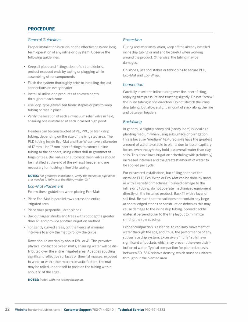
PROCEDURE
General Guidelines
Proper installation is crucial to the effectiveness and long-
term operation of any inline drip system. Observe the
following guidelines:
Headers can be constructed of PE, PVC, or blank drip
tubing, depending on the size of the irrigated area. The
PLD tubing inside Eco-Mat and Eco-Wrap have a diameter
of 17 mm. Use 17 mm insert fittings to connect inline
tubing to the headers, using either drill-in grommet fit-
tings or tees. Ball valves or automatic flush valves should
be installed at the end of the exhaust header and are
necessary for flushing inline drip tubing.
NOTES: For grommet installation, verify the minimum pipe diam-eter needed to fully seat the fitting—often 1¼".
Eco-Mat Placement Follow these guidelines when placing Eco-Mat:
Rows should overlap by about 12%, or 4". This provides
physical contact between mats, ensuring water will be dis-
tributed over the entire irrigated area. At edges abutting
significant reflective surfaces or thermal masses, exposed
to wind, or with other micro-climactic factors, the mat
may be rolled under itself to position the tubing within
about 8" of the edge.
NOTES: Install with the tubing facing up.
Protection
During and after installation, keep off the already installed
inline drip tubing or mat and be careful when working
around the product. Otherwise, the tubing may be
damaged.
On slopes, use sod stakes or fabric pins to secure PLD,
Eco-Mat and Eco-Wrap.
Connection
Carefully insert the inline tubing over the insert fitting,
applying firm pressure and twisting slightly. Do not “screw”
the inline tubing in one direction. Do not stretch the inline
drip tubing, but allow a slight amount of slack along the line
and between headers.
Backfilling
In general, a slightly sandy soil (sandy loam) is ideal as a
planting medium when using subsurface drip irrigation.
This is because “medium” textured soils have the greatest
amount of water available to plants due to lesser capillary
forces, even though they hold less overall water than clay
soils. This also allows irrigation scheduling with (relatively)
increased intervals and the greatest amount of water to
be applied per cycle.
For excavated installations, backfilling on top of the
installed PLD, Eco-Wrap or Eco-Mat can be done by hand
or with a variety of machines. To avoid damage to the
inline drip tubing, do not operate mechanized equipment
directly on the installed product. Backfill with a layer of
soil first. Be sure that the soil does not contain any large
or sharp-edged stones or construction debris as this may
cause damage to the inline drip tubing. Spread backfill
material perpendicular to the line layout to minimize
shifting the row spacing.
Proper compaction is essential to capillary movement of
water through the soil, and, thus, the performance of any
subsurface drip system. Excessively “fluffy” soils have
significant air pockets which may prevent the even distri-
bution of water. Typical compaction for planted areas is
between 80–85% relative density, which must be uniform
throughout the planted area.
• Keep all pipes and fittings clear of dirt and debris, protect exposed ends by taping or plugging while assembling other components
• Flush the system thoroughly prior to installing the last connections on every header
• Install all inline drip products at an even depth throughout each zone
• Use loop-type galvanized fabric staples or pins to keep tubing or mat in place
• Verify the location of each air/vacuum relief valve in field, ensuring one is installed at each localized high point
• Place Eco-Mat in parallel rows across the entire irrigated area
• Place rows perpendicular to slopes
• Box out larger shrubs and trees with root depths greater than 12" and provide another irrigation method
• For gently curved areas, cut the fleece at minimal intervals to allow the mat to follow the curve
23 Learn more. Visit hunterindustries.com or contact your local sales manager.
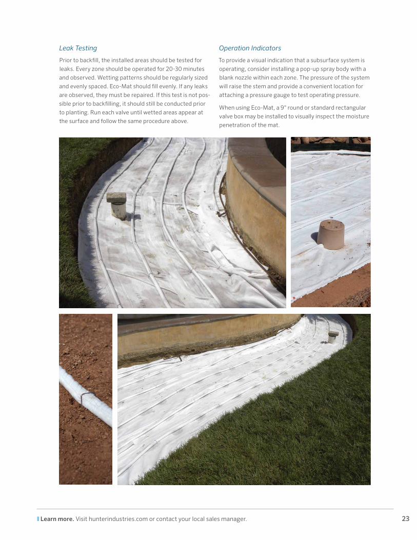
Leak Testing
Prior to backfill, the installed areas should be tested for
leaks. Every zone should be operated for 20-30 minutes
and observed. Wetting patterns should be regularly sized
and evenly spaced. Eco-Mat should fill evenly. If any leaks
are observed, they must be repaired. If this test is not pos-
sible prior to backfilling, it should still be conducted prior
to planting. Run each valve until wetted areas appear at
the surface and follow the same procedure above.
Operation Indicators
To provide a visual indication that a subsurface system is
operating, consider installing a pop-up spray body with a
blank nozzle within each zone. The pressure of the system
will raise the stem and provide a convenient location for
attaching a pressure gauge to test operating pressure.
When using Eco-Mat, a 9" round or standard rectangular
valve box may be installed to visually inspect the moisture
penetration of the mat.
24 Website hunterindustries.com | Customer Support 760-744-5240 | Technical Service 760-591-7383
OPERATION AND MAINTENANCE
INITIAL OPERATION
Before the initial operation, all pipes should be flushed
with open flush valves on exhaust headers to remove any
debris in the inline drip tubing.
During plant establishment you’ll need to irrigate close
to or at the soil’s maximum carrying capacity to train
roots to grow toward the wetted area. Once the roots are
established, overhead irrigation can be stopped. This
typically takes from three to six weeks.
When germinating seed, overhead irrigation is essential,
in addition to regular operation of the inline irrigation
system. The overhead irrigation can be stopped when the
seedings and roots develop.
When establishing sod, run the subsurface irrigation
system long enough to reach the soil’s carrying capacity
until the roots knit with the soil. Ensure proper contact
between the sod and the wetted soil by rolling. Overhead
irrigation is recommended when the sod is first installed
(to water in the sod and prevent drying out) and generally
is not otherwise needed.
Especially during the first weeks after the installation of
any irrigation system, the system should be inspected
regularly to verify appropriate water application and
adjust irrigation scheduling as required.
Recommended System Inspection
• Water source
• Control valve
• Filter, including specified filter element
• Tubing and connections
• Air relief valves
• Flush valves
1. Review the installation and make sure the specified components have been installed. Check markings on the inline drip tubing to ensure authentic Hunter products have been used. Verify row spacing (and for PLD, emitter spacing per specified product).
2. Verify the following are installed and check for leaks while operating:
3. Run the system for an extended period and observe the wetted pattern (if possible). Verify consistent wetting pattern is evident on the surface.
4. Measure the pressure at the control valve and at each flush valve. Record the pressure and note for reference to aid future troubleshooting.
5. Note the current controller schedule per valve, including run time, days per week, and flow (if available).
25 Learn more. Visit hunterindustries.com or contact your local sales manager.
SCHEDULING
If no regular operating schedule has been prepared, the
controller may be programmed using recommended
times listed in the chart below as a guideline. The values
in the table below are based on broad generic information
(without considering specific plant, climate, or soil condi-
tions). The optimum run time and frequency will depend
on many factors.
For all inline drip products, pulsing (scheduling several
shorter irrigation phases per day instead of one long
phase) promotes capillary distribution of water. This
avoids saturating the soil and is recommended for any run
time longer than 12 minutes. Pulsing can be done by set-
ting multiple start times or using Hunter controllers with
an automatic “Cycle and Soak” feature. For more informa-
tion, see http://www.hunterindustries.com.
Scheduling is key to preventing root intrusion. By main-
taining a consistent and healthy level of moisture in the
soil, roots will exhibit strong and consistent growth and
will not need to seek out “new” sources of water.
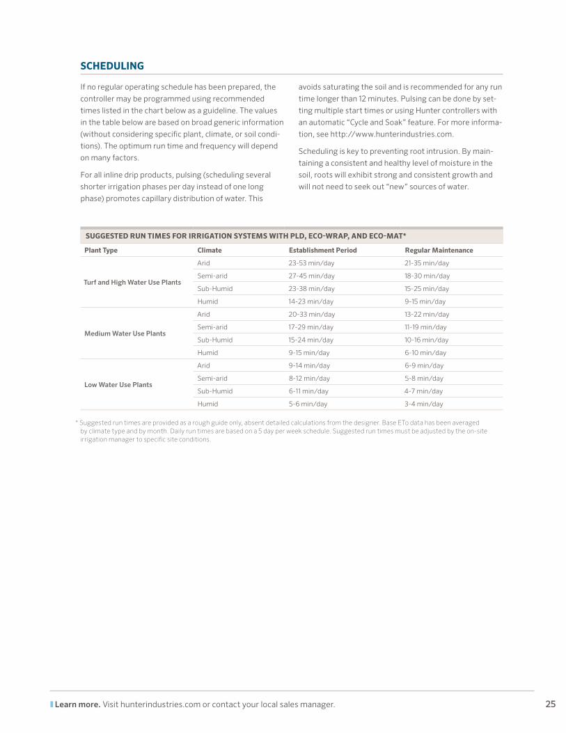
SUGGESTED RUN TIMES FOR IRRIGATION SYSTEMS WITH PLD, ECO-WRAP, AND ECO-MAT*
Plant Type Climate Establishment Period Regular Maintenance
Turf and High Water Use Plants
Arid 23-53 min/day 21-35 min/day
Semi-arid 27-45 min/day 18-30 min/day
Sub-Humid 23-38 min/day 15-25 min/day
Humid 14-23 min/day 9-15 min/day
Medium Water Use Plants
Arid 20-33 min/day 13-22 min/day
Semi-arid 17-29 min/day 11-19 min/day
Sub-Humid 15-24 min/day 10-16 min/day
Humid 9-15 min/day 6-10 min/day
Low Water Use Plants
Arid 9-14 min/day 6-9 min/day
Semi-arid 8-12 min/day 5-8 min/day
Sub-Humid 6-11 min/day 4-7 min/day
Humid 5-6 min/day 3-4 min/day
* Suggested run times are provided as a rough guide only, absent detailed calculations from the designer. Base ETo data has been averaged by climate type and by month. Daily run times are based on a 5 day per week schedule. Suggested run times must be adjusted by the on-site irrigation manager to specific site conditions.
26 Website hunterindustries.com | Customer Support 760-744-5240 | Technical Service 760-591-7383
MAINTENANCE
Flushing
Flushing inline drip irrigation systems is a crucial main-
tenance procedure. If used, automatic flushing valves
help avoid, but may not prevent, particulate build-up.
At a minimum, manual flushing and visual inspection of
the water is recommended annually. To manually flush
a system with automatic flush valves, disassemble or
remove the flush valves first.
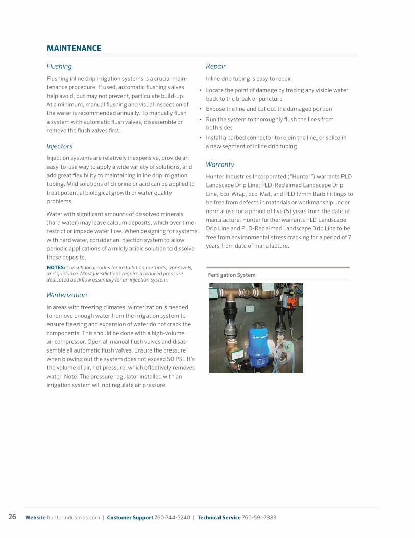
Injectors
Injection systems are relatively inexpensive, provide an
easy-to-use way to apply a wide variety of solutions, and
add great flexibility to maintaining inline drip irrigation
tubing. Mild solutions of chlorine or acid can be applied to
treat potential biological growth or water quality
problems.
Water with significant amounts of dissolved minerals
(hard water) may leave calcium deposits, which over time
restrict or impede water flow. When designing for systems
with hard water, consider an injection system to allow
periodic applications of a mildly acidic solution to dissolve
these deposits.
NOTES: Consult local codes for installation methods, approvals, and guidance. Most jurisdictions require a reduced pressure dedicated backflow assembly for an injection system.
Winterization
In areas with freezing climates, winterization is needed
to remove enough water from the irrigation system to
ensure freezing and expansion of water do not crack the
components. This should be done with a high-volume
air compressor. Open all manual flush valves and disas-
semble all automatic flush valves. Ensure the pressure
when blowing out the system does not exceed 50 PSI. It’s
the volume of air, not pressure, which effectively removes
water. Note: The pressure regulator installed with an
irrigation system will not regulate air pressure.
Repair
Inline drip tubing is easy to repair:
Warranty
Hunter Industries Incorporated (“Hunter”) warrants PLD
Landscape Drip Line, PLD-Reclaimed Landscape Drip
Line, Eco-Wrap, Eco-Mat, and PLD 17mm Barb Fittings to
be free from defects in materials or workmanship under
normal use for a period of five (5) years from the date of
manufacture. Hunter further warrants PLD Landscape
Drip Line and PLD-Reclaimed Landscape Drip Line to be
free from environmental stress cracking for a period of 7
years from date of manufacture.
Fertigation System
• Locate the point of damage by tracing any visible water back to the break or puncture
• Expose the line and cut out the damaged portion
• Run the system to thoroughly flush the lines from both sides
• Install a barbed connector to rejoin the line, or splice in a new segment of inline drip tubing
27 Learn more. Visit hunterindustries.com or contact your local sales manager.
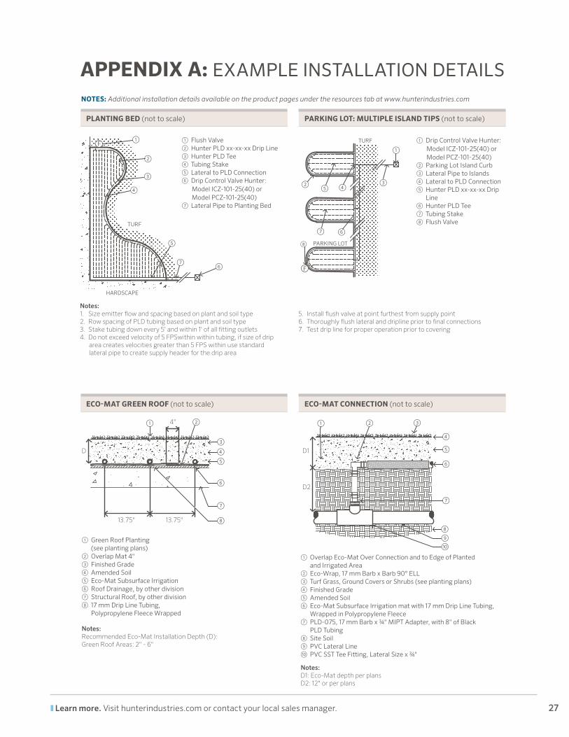
APPENDIX A: EXAMPLE INSTALLATION DETAILS NOTES: Additional installation details available on the product pages under the resources tab at www.hunterindustries.com
HARDSCAPE
TURF
①
②
③
④
⑤
⑦⑥
① Flush Valve② Hunter PLD xx-xx-xx Drip Line③ Hunter PLD Tee④ Tubing Stake⑤ Lateral to PLD Connection⑥ Drip Control Valve Hunter: Model ICZ-101-25(40) or Model PCZ-101-25(40)⑦ Lateral Pipe to Planting Bed
Notes:1. Size emitter �ow and spacing based on plant and soil type2. Row spacing of PLD tubing based on plant and soil type3. Stake tubing down every 5' and within 1' of all �tting outlets4. Do not exceed velocity of 5 FPSwithin tubing, if size of drip area
creates velocities greater than 5 FPSwithin use standard lateral pipe to create supply header for the drip area
5. Install �ush valve at point furthest from supply point6. Thoroughly �ush lateral and dripline prior to �nal connections7. Test drip line for proper operation prior to covering
F
① Overlap Eco-Mat Over Connection and to Edge of Planted and Irrigated Area② Eco-Wrap, 17 mm Barb x Barb 90° ELL③ Turf Grass, Ground Covers or Shrubs (see planting plans)④ Finished Grade⑤ Amended Soil⑥ Eco-Mat Subsurface Irrigation mat with 17 mm Drip Line Tubing, Wrapped in Polypropylene Fleece⑦ PLD-075, 17 mm Barb x ¾" MIPT Adapter, with 8" of Black PLD Tubing⑧ Site Soil⑨ PVC Lateral Line⑩ PVC SST Tee Fitting, Lateral Size x ¾"
Notes:D1: Eco-Mat depth per plansD2: 12" or per plans
① ② ③
④
⑤
⑥
⑧
⑦
⑨⑩
D1
D2
① Drip Control Valve Hunter: Model ICZ-101-25(40) or Model PCZ-101-25(40)② Parking Lot Island Curb③ Lateral Pipe to Islands④ Lateral to PLD Connection⑤ Hunter PLD xx-xx-xx Drip Line⑥ Hunter PLD Tee⑦ Tubing Stake➇ Flush Valve
Notes:1. Size emitter �ow and spacing based on plant and soil type2. Row spacing of PLD tubing based on plant and soil type3. Stake tubing down every 5' and within 1' of all �tting outlets4. Do not exceed velocity of 5 FPSwithin within tubing, if size of drip
area creates velocities greater than 5 FPS within use standard lateral pipe to create supply header for the drip area
5. Install �ush valve at point furthest from supply point6. Thoroughly �ush lateral and dripline prior to �nal connections7. Test drip line for proper operation prior to covering
F
①
② ③④⑤
⑦ ⑥
➇
TURF
PARKING LOT
PLANTING BED (not to scale) PARKING LOT: MULTIPLE ISLAND TIPS (not to scale)
① Green Roof Planting (see planting plans)② Overlap Mat 4" ③ Finished Grade④ Amended Soil⑤ Eco-Mat Subsurface Irrigation⑥ Roof Drainage, by other division⑦ Structural Roof, by other division➇ 17 mm Drip Line Tubing, Polypropylene Fleece Wrapped
Notes:Recommended Eco-Mat Installation Depth (D):Green Roof Areas: 2" - 6"
13.75"
D
13.75"
4"①
③④⑤
⑥
⑦
⑧
②
ECO-MAT GREEN ROOF (not to scale) ECO-MAT CONNECTION (not to scale)
Notes:1. Size emitter �ow and spacing based on plant and soil type2. Row spacing of PLD tubing based on plant and soil type3. Stake tubing down every 5' and within 1' of all �tting outlets4. Do not exceed velocity of 5 FPSwithin within tubing, if size of drip
area creates velocities greater than 5 FPS within use standard lateral pipe to create supply header for the drip area
5. Install �ush valve at point furthest from supply point6. Thoroughly �ush lateral and dripline prior to �nal connections7. Test drip line for proper operation prior to covering

28 Website hunterindustries.com | Customer Support 760-744-5240 | Technical Service 760-591-7383
APPENDIX B: TECHNICAL PRODUCT DATA
COEFFICIENT OF VARIATION
NOTES: Hunter publishes CV values for all pressures throughout the operating range. For best performance, regulate inline pressures to 30 PSI.
15 PSI – 1.2
20 PSI – 1.7
25 PSI – 0.9
30 PSI – 0.6
35 PSI – 1.1
40 PSI – 3.4
45 PSI – 4.2
50 PSI – 4.8
PLD
PLD Application Rates
PLD Flow Conversion Chart
ECO-WRAP
EMITTER FLOW RATE – 1.0 GPH
Row Spacing (in.)
Emitter Spacing (in.)
12 18 24
12 1.60 1.07 0.80
14 1.38 0.92 0.69
16 1.20 0.80 0.60
18 1.07 0.71 0.53
20 0.96 0.64 0.4824 0.80 0.53 0.40
NotesApplication rates in inches per hour
EMITTER LINE LENGTH – 0.4 GPH
Pressure(PSI)
Emitter Spacing (in.)
12 18 24
15.0 289 401 502
20.0 354 494 620
25.0 405 563 706
30.0 441 621 783
35.0 481 671 842
40.0 508 719 910
45.0 542 755 94950.0 558 784 988
EMITTER LINE LENGTH – 0.6 GPH
Pressure(PSI)
Emitter Spacing (in.)
12 18 24
15.0 173 240 300
20.0 230 320 402
25.0 265 373 471
30.0 299 417 523
35.0 333 462 580
40.0 342 483 611
45.0 364 518 65750.0 387 543 685
EMITTER LINE LENGTH – 1.0 GPH
Pressure(PSI)
Emitter Spacing (in.)
12 18 24
15.0 126 176 222
20.0 169 235 295
25.0 197 276 346
30.0 218 308 390
35.0 240 337 425
40.0 263 362 452
45.0 271 384 48650.0 288 401 503
EMITTER FLOW RATE – 0.6 GPH
Row Spacing (in.)
Emitter Spacing (in.)
12 18 24
12 0.96 0.64 0.48
14 0.83 0.55 0.41
16 0.72 0.48 0.36
18 0.64 0.43 0.32
20 0.58 0.39 0.2924 0.48 0.32 0.24
EMITTER FLOW RATE – 0.4 GPH
Row Spacing (in.)
Emitter Spacing (in.)
12 18 24
12 0.64 0.43 0.32
14 0.55 0.37 0.28
16 0.48 0.32 0.24
18 0.43 0.29 0.21
20 0.39 0.26 0.1924 0.32 0.21 0.16
PLD EMITTER LINE MAXIMUM LENGTH CHARTS
PLD APPLICATION RATES
QUICK REFERENCE CHART – GPM PER 100'
Emitter(GPH)
Emitter Spacing (in.)
12 18 24
0.4 0.67 0.44 0.33
0.6 1.00 0.67 0.501.0 1.67 1.11 0.83
PLD FLOW CONVERSION CHARTS
• Outside diameter drip pipe: 17 mm
• Quantity of water per dripper: 0.6 GPH, pressure compensating, non-draining
• Emitter spacing: 12"
• Outside diameter of enveloped pipe: 14"
• Roll Length: 250 ft.
• Maximum lateral length (depends on pressure): up to 387 ft.
• Working pressure range: 15-50 PSI
• Weight per roll: 17 lbs.
• Measurement per roll: - Outside diameter: 36" - Inside diameter: 16" - Width: 17"
• Rolls per pallet: 20
29 Learn more. Visit hunterindustries.com or contact your local sales manager.
ECO-MAT
FITTINGS
INSERT FITTINGS
MODEL DESCRIPTION
PLD050 Barb to ½" NPT Adapter
PLD075 Barb to ¾" NPT Adapter
PLDCPL Barb to Barb Coupling
PLDELB Barb to Barb, 90° Elbow
PLDTEE Barbed Tee
PLDCAP Barb to End Cap
PLDBV Barbed Valve
PLD075TBTEE ¾" Female Thread x 17 mm Barb Tee
PLDAVR Air Relief Valve
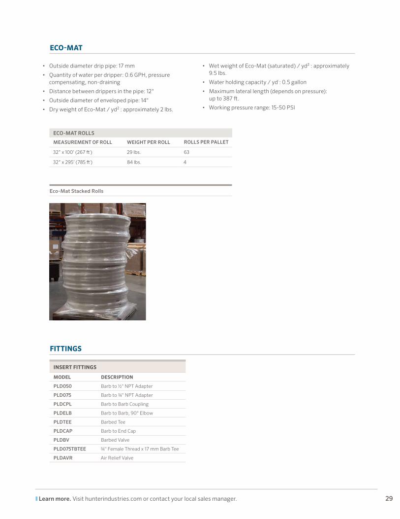
Eco-Mat Stacked Rolls
• Outside diameter drip pipe: 17 mm
• Quantity of water per dripper: 0.6 GPH, pressure compensating, non-draining
• Distance between drippers in the pipe: 12"
• Outside diameter of enveloped pipe: 14"
• Dry weight of Eco-Mat / yd² : approximately 2 lbs.
• Wet weight of Eco-Mat (saturated) / yd² : approximately 9.5 lbs.
• Water holding capacity / yd2 : 0.5 gallon
• Maximum lateral length (depends on pressure): up to 387 ft.
• Working pressure range: 15-50 PSI
ECO-MAT ROLLS
MEASUREMENT OF ROLL WEIGHT PER ROLL ROLLS PER PALLET
32” x 100’ (267 ft2) 29 lbs. 63
32” x 295’ (785 ft2) 84 lbs. 4
Helping our customers succeed is what drives us. While our passion
for innovation and engineering is built into everything we do, it is our
commitment to exceptional support that we hope will keep you in
the Hunter family of customers for years to come.
© 2012 Hunter Industries Incorporated Please recycle. LIT-496 B 6/15
This brochure was printed on Forest Stewardship Council™ (FSC) certified paper with soy inks. The FSC is an international organization established to promote the responsible management of the world’s forests. FSC
Website hunterindustries.com | Customer Support 760-744-5240 | Technical Service 760-591-7383
Printed using 100% Wind Energy, (RECs)
Gregory R. Hunter, President of Hunter Industries
Top Related