


Languages
Pages
Legal

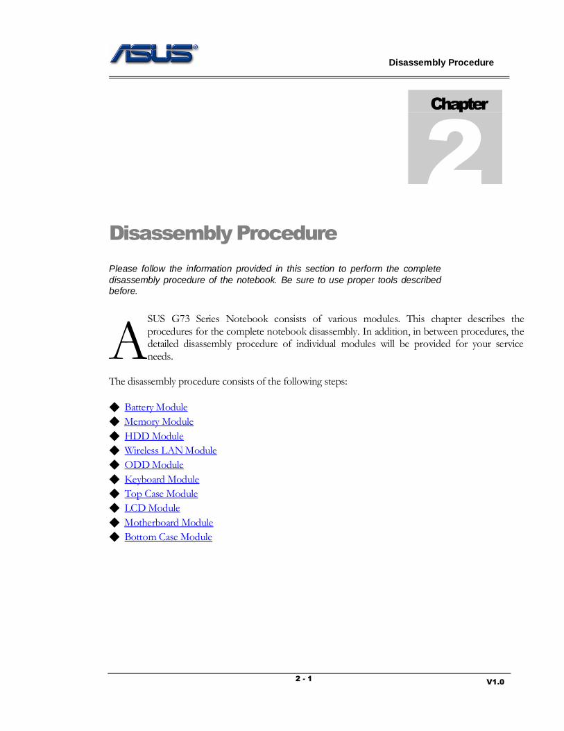
Disassembly Procedure
V1.0 2 - 1
Disassembly Procedure
Please follow the information provided in this section to perform the complete
disassembly procedure of the notebook. Be sure to use proper tools described
before.
SUS G73 Series Notebook consists of various modules. This chapter describes the
procedures for the complete notebook disassembly. In addition, in between procedures, the detailed disassembly procedure of individual modules will be provided for your service
needs.
The disassembly procedure consists of the following steps:
◆ Battery Module
◆ Memory Module
◆ HDD Module
◆ Wireless LAN Module
◆ ODD Module
◆ Keyboard Module
◆ Top Case Module
◆ LCD Module
◆ Motherboard Module
◆ Bottom Case Module
Chapter
2
A

Disassembly Procedure
V1.0 2 - 2
Battery Module
The illustration below shows how to remove the battery module.
Remove Battery Module
Open latch 1 and hold the latch 2 when take the battery away.
BACK
Memory Module
The illustration shows how to remove the Memory Module form the notebook.
Remove Memory Module
1. Remove 2 screws (M2.5*5) on the bottom door and take away the bottom door.
B A T T E R Y
M E M O R Y
Disassembly Procedure
V1.0 2 - 3
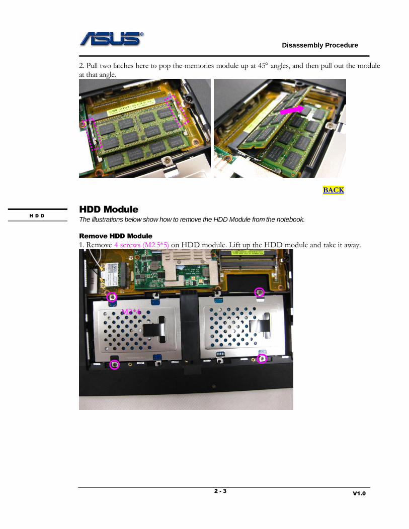
2. Pull two latches here to pop the memories module up at 45 angles, and then pull out the module at that angle.
BACK
HDD Module
The illustrations below show how to remove the HDD Module from the notebook.
Remove HDD Module
1. Remove 4 screws (M2.5*5) on HDD module. Lift up the HDD module and take it away.
H D D
M2*4

Disassembly Procedure
V1.0 2 - 4
2. Remove 4 screws (M3*4) to separate HDD from HDD housing
BACK
M3*3 M3*3
Disassembly Procedure
V1.0 2 - 5
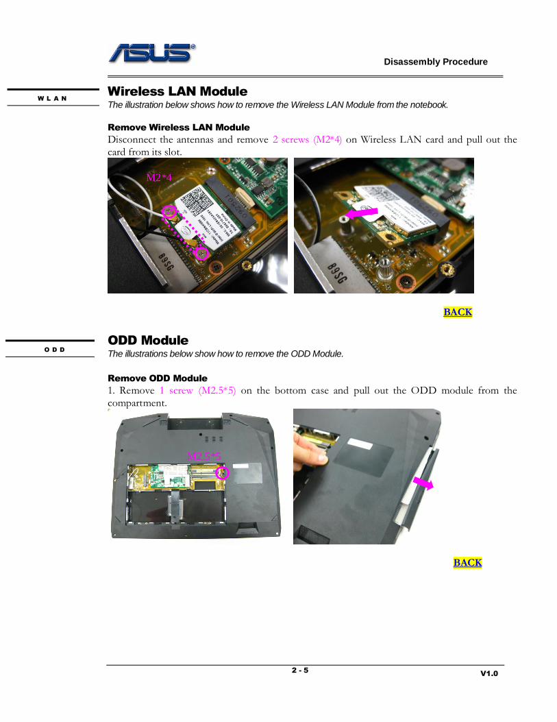
Wireless LAN Module
The illustration below shows how to remove the Wireless LAN Module from the notebook.
Remove Wireless LAN Module
Disconnect the antennas and remove 2 screws (M2*4) on Wireless LAN card and pull out the
card from its slot.
BACK
ODD Module
The illustrations below show how to remove the ODD Module.
Remove ODD Module
1. Remove 1 screw (M2.5*5) on the bottom case and pull out the ODD module from the
compartment.
BACK
O D D
W L A N
M2*4
M2.5*5

Disassembly Procedure
V1.0 2 - 6
Keyboard Module
The illustrations below show how to remove the Keyboard and disassemble the Keyboard Cover.
Remove the Keyboard
1. Open 5 latches (ESC, F5, F9, PrtSc and End) on keyboard module by a pair of tweezers.
2. Turn over the keyboard plate and disconnect the keyboard FPC, LED FPC and remove the
keyboard plate.
K E Y B O A R
Disassembly Procedure
V1.0 2 - 7
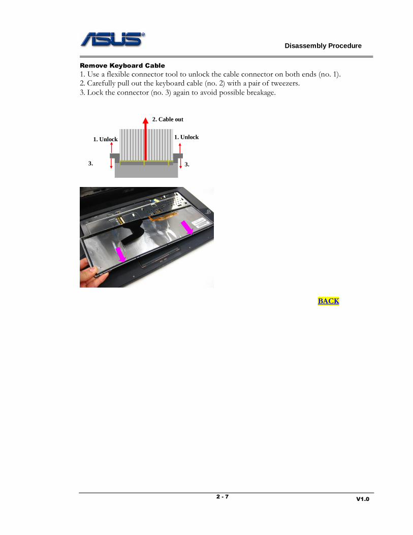
Remove Keyboard Cable
1. Use a flexible connector tool to unlock the cable connector on both ends (no. 1). 2. Carefully pull out the keyboard cable (no. 2) with a pair of tweezers.
3. Lock the connector (no. 3) again to avoid possible breakage.
BACK
1. Unlock
2. Cable out
3.
Lock
1. Unlock
3.
Lock

Disassembly Procedure
V1.0 2 - 8
Top Case Module
The illustrations below show how to remove and disassemble the Top Case Module of the notebook.
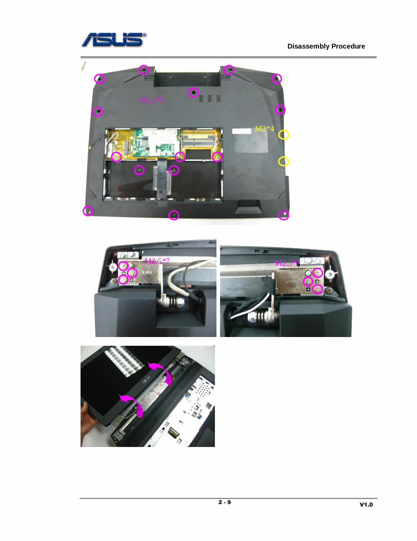
Remove the Top Case Module
1. Remove 2 screws (M2*4) on the bottom case. Then pry the hinge cover by a plastic blade and
remove the hinge cover.
2. Remove 17 screws (M2.5*5, M2*4) on the bottom case. Then remove 6 screws (M2.5*7) on the LCD hinges and lay down the LCD module.
T O P C A S E
M2*4
Disassembly Procedure
V1.0 2 - 9
M2.5*5
M2*4
M2.5*7 M2.5*7

Disassembly Procedure
V1.0 2 - 10
3. Remove 6 screws (M2.5*5) on the top case. Then disconnect the switch board FPC, speaker cable and the touchpad FPC.
4. Pry the edges of the top case and remove the top case to take it away.
Switch Board
FPC Speaker cable
Touchpad FPC
M2.5*5

Disassembly Procedure
V1.0 2 - 11
Disassemble the Top Case Module
5. Tear off the mylars on the touchpad. Remove 2 screws (M2*5) on the touchpad bracket. Disconnect the touchpad FPC and remove the touchpad module.
6. Remove 2 screws (M2.5*5) on the touchpad bracket and separate the touchpad board and the
touchpad bracket.
M2*3

Disassembly Procedure
V1.0 2 - 12
7. Remove 3 screws (M2*3) on the power switch board. Remove the power switch board from the
top case.
8. Remove 1 screw (M2.5*5) on the speaker and take away the speaker.
BACK
M2.5*5
M2*3
M2.5*5

Disassembly Procedure
V1.0 2 - 13
LCD Module
The illustrations below show how to remove and disassemble the LCD Module.
Remove the LCD Module
1. Disconnect the following the cable from the motherboard: LCD light bar cable, LVDS cable,
CMOS MIC cable. Pull out the WLAN antennas from the hole in the motherboard. Pry the latch fixing the cables and release the cables. Separate the LCD module from the whole system.
L C D
CMOS MIC cable
LVDS cable
LCD Light Bar cable Pull out the WLAN
antennas from the hole here.

Disassembly Procedure
V1.0 2 - 14
Disassemble the LCD Module
2. Remove 2 screws (M2.5*6) on the LCD bezel. Pry the edges of LCD bezel and remove the front bezel.
M2.5*6
Disassembly Procedure
V1.0 2 - 15
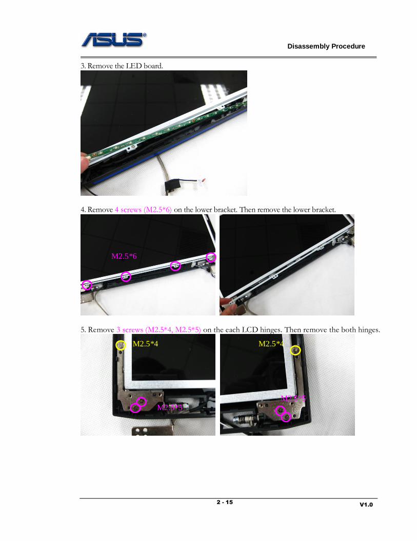
3. Remove the LED board.
4. Remove 4 screws (M2.5*6) on the lower bracket. Then remove the lower bracket.
5. Remove 3 screws (M2.5*4, M2.5*5) on the each LCD hinges. Then remove the both hinges.
M2.5*6
M2.5*5 M2.5*5
M2.5*4 M2.5*4
Disassembly Procedure
V1.0 2 - 16
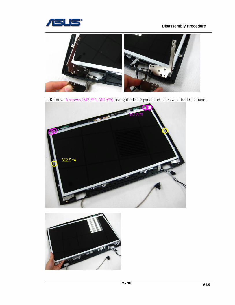
5. Remove 6 screws (M2.5*4, M2.5*5) fixing the LCD panel and take away the LCD panel.
M2.5*5
M2.5*4

Disassembly Procedure
V1.0 2 - 17
6. Remove 4 screws (M2.5*4) on the LCD up bracket and remove the up bracket.
7. Disconnect the camera and its cable. Then remove the CMOS MIC cable from its cover.
M2.5*4

Disassembly Procedure
V1.0 2 - 18
8. Disconnect the LVDS cable from the LCD panel. Remove 8 screws (M2*3) on the LCD brackets and separate the LCD brackets.
BACK
M2*3 M2*3

Disassembly Procedure
V1.0 2 - 19
Motherboard Module
The illustrations below show how to disassemble and remove the Motherboard Module.
Remove the Motherboard Module
1. Remove 3 screws (M2*6) on each fan. Disconnect the fan cables. Remove 2 fans.
2. Remove 3 screws (M2.5*5) on the motherboard. Then disconnect the following cables: LAN board cable, Bluetooth cable, audio board cable and the SATA FFC. Remove the motherboard
from the bottom case.
M O T H E R B O A R D
M2*6
M2*6

Disassembly Procedure
V1.0 2 - 20
M2.5*5
LAN board cable
Bluetooth cable
Audio board cable SATA FFC

Disassembly Procedure
V1.0 2 - 21
Disassemble the Motherboard Module
3. Remove 4 screws (M2*4) on the heat sink. Then remove the heat sink.
4. Using the single slot screw driver to turn the non-removable screw to loosen the CPU. Then suck up the CPU by the vacuum handling tool.
5. Loosen 4 screws on the VGA thermal. Then remove the thermal. Remove 2 screws (M2*3) on the VGA card and remove the VGA card.
M2*4
Disassembly Procedure
V1.0 2 - 22
BACK
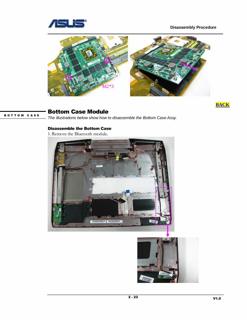
Bottom Case Module
The illustrations below show how to disassemble the Bottom Case Assy.
Disassemble the Bottom Case
1. Remove the Bluetooth module.
B O T T O M C A S E
M2*3

Disassembly Procedure
V1.0 2 - 23
2. Remove 2 screws (M2*4) fixing the HDD board and remove it. Remove 2 screws to separate the HDD board and its bracket.
3. Remove 2 screws (M2.5*5) on the audio board. Turn over the audio board and disconnect the speaker cable. Remove the audio board and the speaker.
M2*4
M2*4
M2.5*5
Disassembly Procedure
V1.0 2 - 24
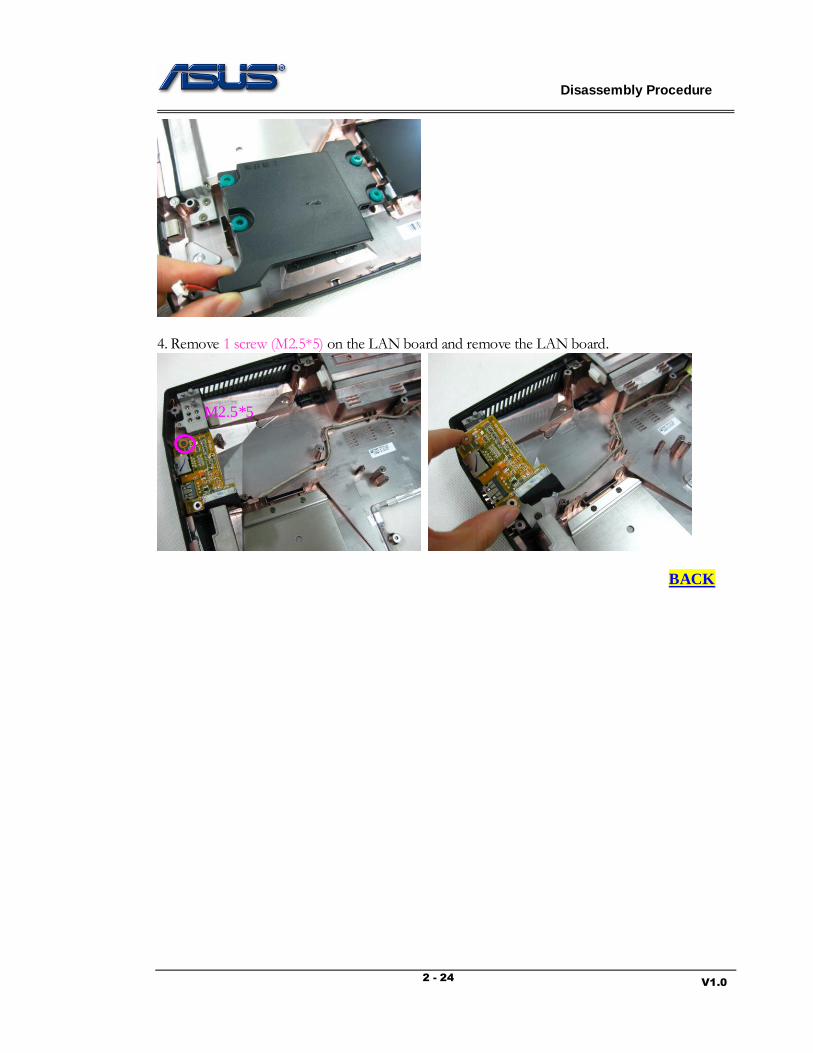
4. Remove 1 screw (M2.5*5) on the LAN board and remove the LAN board.
BACK
M2.5*5
Top Related