


Languages
Pages
Legal


Digital Relays and Capacitive Voltage Transformers:Balancing Speed and Transient Overreach
GER-3986

5 3 r d A n n u a l C o n f e r e n c e f o r P r o t e c t i v e R e l a y E n g i n e e r s
DISTANCE RELAYS AND
CAPACITIVE VOLTAGE TRANSFORMERS —BALANCING SPEED AND TRANSIENT OVERREACH
Bogdan [email protected]
(905) 201 2199
Dave Sharples*
[email protected](905) 201 2168
Vince [email protected]
(905) 201 2108
Marzio [email protected]
(905) 201 2056
GE Power Management215 Anderson Avenue
Markham, OntarioCanada L6E 1B3
*Consultant
College Station, April 11-13, 2000
Distance Relays and Capacitive Voltage Transformers – Balancing Speed and Transient Overreach
Page 2 of 22
1. Introduction
Capacitive Voltage Transformers (CVTs) are the predominant source of the voltage signalsfor distance relays in High Voltage (HV) and Extra High Voltage (EHV) systems.
CVTs provide a cost-efficient way of obtaining secondary voltages for EHV systems. Theycreate however, certain problems for distance relays. During line faults, when the primary volt-age collapses and the energy stored in the stack capacitors and the tuning reactor of a CVT needsto be dissipated, the CVT generates severe transients that affect the performance of protectiverelays.
The CVT caused transients are of significant magnitude and comparatively long duration.This becomes particularly important for large Source Impedance Ratios (SIR — the ratio of thesystem equivalent impedance and the relay reach impedance) when the fault loop voltage can beas low as a few percent of the nominal voltage for faults at the relay reach point. Such a smallsignal is buried beneath the CVT transient making it extremely difficult to distinguish quicklybetween faults at the reach point and faults within the protection zone.
Electromechanical relays can cope with unfavorable CVT transients due to their natural me-chanical inertia at the expense of slower operation.
Digital relays are designed for high-speed tripping and therefore they face certain CVT-related problems.
CVT transients can affect both the transient overreach (a relay operates during faults locatedout of its set reach) and the speed of operation (slow tripping for high SIRs) and directionality.
This paper begins with analysis of the CVT transients (Section 2). The influence of the CVTtransients on the performance of digital distance relays follows (Sections 3 and 4). A new algo-rithm balancing transient overreach and speed of operation, its hardware implementation and theresults of testing are presented in Section 5. The paper discusses transient overreach issues ratherthen directionality as the latter is effectively controlled with the memory polarization.
2. CVT Transients
2.1. Equivalent circuit of a CVT
A generic CVT consists of a capacitve voltage divider, tuning reactor, step-down transformerand ferroresonance suppression circuit (the additional communication equipment is not siginifi-cant in these considerations).
Under line fault conditions, when the voltage drops and there is no threat of exceeding theknee-point of the magnetizing characteristic of the step-down transformer, a CVT can be repre-sented by the equivalent linear circuit as shown in Figure 1. The analyzed CVT contains a par-ticular ferroresonance suppression circuit. The analysis, however, is similar to other types offerroresonance circuits. In this paper we will follow the CVT model shown in Figure 1.
The linear circuit of Figure 1 can be further simplified as shown in Figure 2.

Distance Relays and Capacitive Voltage Transformers – Balancing Speed and Transient Overreach
Page 3 of 22
R
C1
Lf
Rf
f
R0
L0
v2C
T1L
m
RT2
LT2
RT1
LT1
RFe
L
vi
C2
v1
C
Figure 1. Equivalent circuit diagram of a CVT.
R
i
LC
vLf
Rf
fCR
0v
2
Figure 2. Simplified model of a CVT from Figure 1.
The parameters in the circuit of Figure 2 are:
C sum of the stack capacitances,L, R equivalent inductance and resistance, respectively, of the tuning reactor and the
step down transformer,R0 burden resistance,f subscript for parameters of the anti-resonance circuit.
For illustration, in this paper we will follow a numerical example of the following two sample500kV CVTs (all the secondary parameters are re-calculated for the intermediate voltage level):
• CVT-1 (“high-C CVT”):
R0 = 1.03997 105 — load resistance, ΩLf = 315.3 — suppression inductance, HCf = 0.0285 10-6 — suppression capacitance, FRf = 77379 — suppression resistance, ΩR = 3289 — resistance, ΩC = 9.1605 10-8 — sum of dividing capacitances, FL = 76.136 — inductance, H
• CVT-2 (“extra high-C CVT”):
R0 = 2.08584 105 — load resistance, ΩLf = 616.35 — suppression inductance, HCf = 0.01134 10-6 — suppression capacitance, FRf = 148519 — suppression resistance, Ω
Distance Relays and Capacitive Voltage Transformers – Balancing Speed and Transient Overreach
Page 4 of 22
R = 1536 — resistance, ΩC = 0.162442 10-6 — sum of dividing capacitances, FL = 48.136 — inductance, H
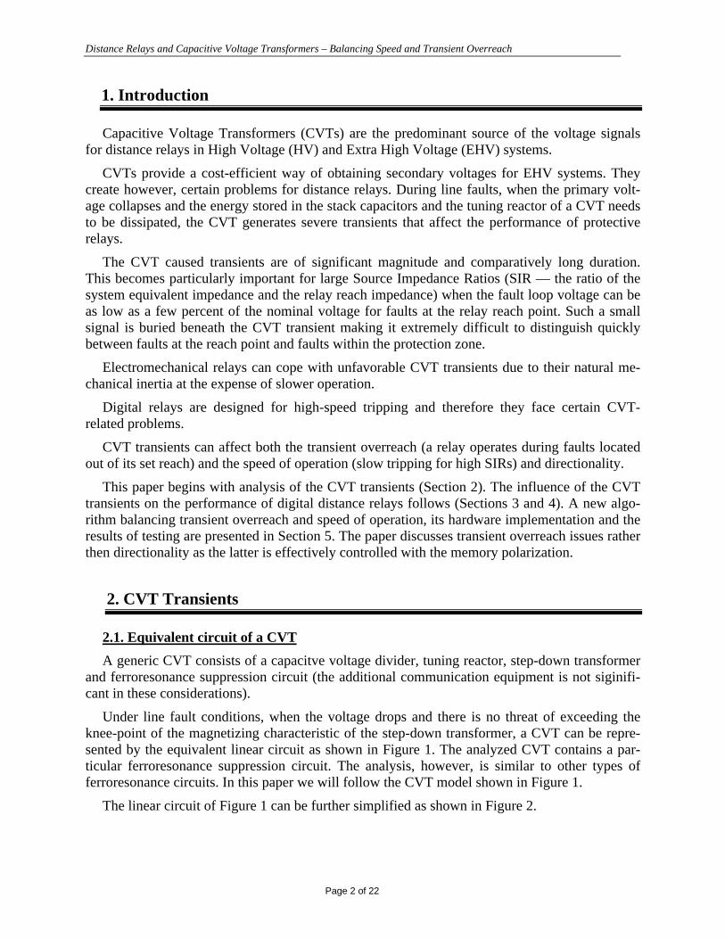
2.2. CVT transients – sample waveforms
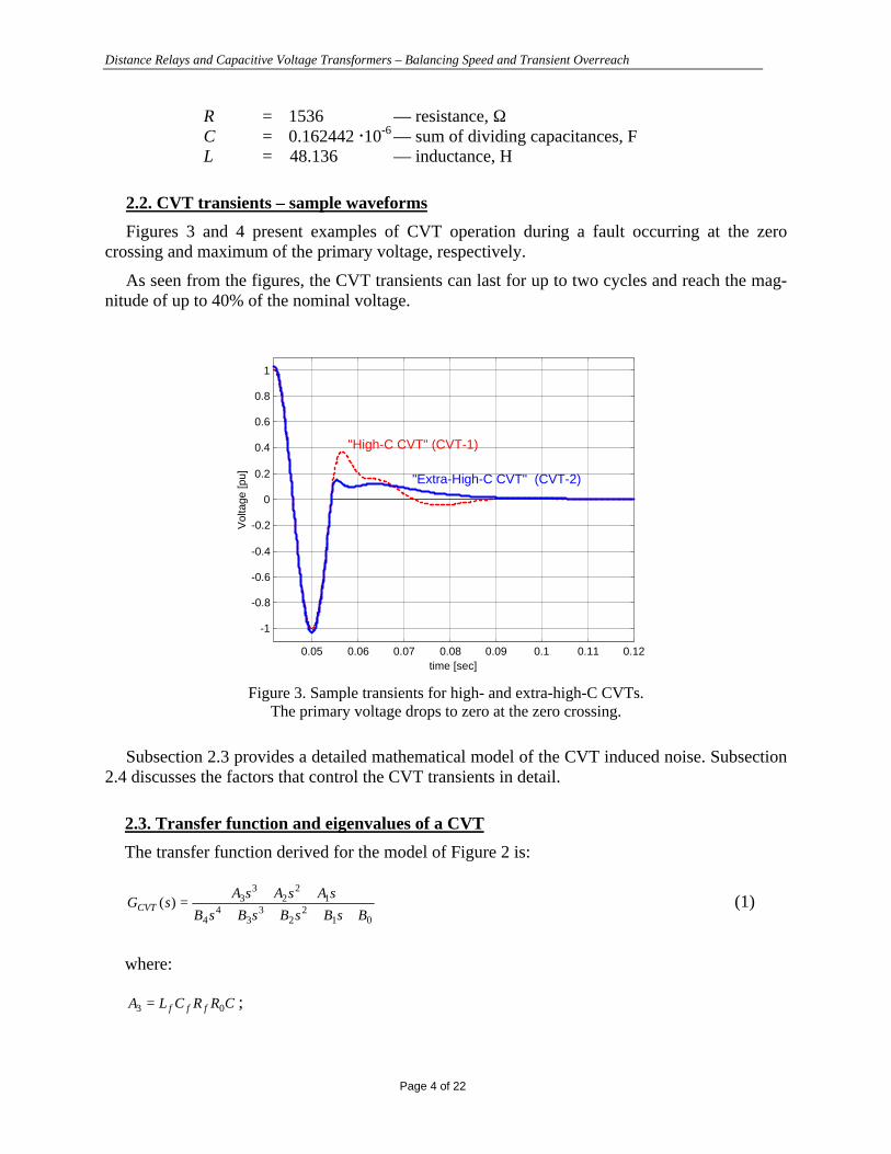
Figures 3 and 4 present examples of CVT operation during a fault occurring at the zerocrossing and maximum of the primary voltage, respectively.
As seen from the figures, the CVT transients can last for up to two cycles and reach the mag-nitude of up to 40% of the nominal voltage.
0.05 0.06 0.07 0.08 0.09 0.1 0.11 0.12
-1
-0.8
-0.6
-0.4
-0.2
0
0.2
0.4
0.6
0.8
1
Vol
tage
[pu]
time [sec]
"High-C CVT" (CVT-1)
"Extra-High-C CVT" (CVT-2)
Figure 3. Sample transients for high- and extra-high-C CVTs.The primary voltage drops to zero at the zero crossing.
Subsection 2.3 provides a detailed mathematical model of the CVT induced noise. Subsection2.4 discusses the factors that control the CVT transients in detail.
2.3. Transfer function and eigenvalues of a CVT
The transfer function derived for the model of Figure 2 is:
012
23
34
4
12
23
3)(BsBsBsBsB
sAsAsAsGCVT
++++++
= (1)
where:
CRRCLA fff 03 = ;
Distance Relays and Capacitive Voltage Transformers – Balancing Speed and Transient Overreach
Page 5 of 22
0.05 0.06 0.07 0.08 0.09 0.1 0.11 0.12
-1
-0.8
-0.6
-0.4
-0.2
0
0.2
0.4
0.6
0.8
1
Vol
tage
[pu]
time [sec]
"Extra-High-C CVT" (CVT-2)
"High-C CVT" (CVT-1)
Figure 4. Sample transients for high- and extra-high-C CVTs.The primary voltage drops to zero from the voltage peak.
CRLA f 02 = ;
CRRA f 01 = ;
LCRRCLB fff )( 04 += ;
CRRCLRRCRCLLCLB fffffff 003 )( +++= ;
CRLRRCLRCLRRLCB ffffff 0002 )()( +++++=
CRRLRRRCB fff 001 )( +++= ;
00 RRB f +=
For example, for CVT-1 (example of a high-C CVT) one obtains:
( )( ) ( )5242
52
)(10626.39.62610401.45.192
10113.15.453739.582
⋅++⋅⋅++
⋅++=
ssss
sssG sCVT (2a)
and for CVT-2 (example of a extra high-C CVT):
( )( ) ( ) ( ) ( )4.1056.2387258.993
10431.18.593245.1784 52
)( +⋅+⋅+⋅+⋅++
=ssss
sssG sCVT (2b)
Distance Relays and Capacitive Voltage Transformers – Balancing Speed and Transient Overreach
Page 6 of 22
The eigenvalues determining the nature of the transient induced by the CVT can be calculatednow from the transfer function. For the two considered CVTs the eigenvalues are:
• CVT-1 (high-C CVT):
-313.43 + j514.13-313.43 - j514.13-96.27 + j186.39-96.27 - j186.39
The above values determine two aperiodically decaying oscillatory components with the fol-lowing time constants and frequencies, respectively:
T = 3.1905 [ms] and f = 81.8261 [Hz]
T = 10.3876 [ms] and f = 29.6647 [Hz]
• CVT-2 (extra high-C CVT):
-993.8011-724.9701-238.6495-105.3577
The above values determine four aperiodically decaying dc components with the time con-stants respectively:
1.0062 [ms]1.3794 [ms]4.1902 [ms]9.4915 [ms]
An extra-high-C CVT has all its eigenvalues real. This results in a decaying non-oscillatorydistortion (see Figure 5 for illustration). A high-C CVT has all its eigenvalues complex (pairs ofconjugate values) resulting in decaying oscillatory distortion (see Figure 6 for illustration).
From the digital signal processing point of view, the values of parameters of the CVT noise donot make the filtering easy. The frequencies of the oscillatory components (high-C CVT) arequite close to 60Hz where the information signal is. In addition, their time constants are in theorder of the power cycle. The time constants of the dc components (extra high-C CVT) are of thesame order (maximum-to-minimum ratio is about 10) — this means that none of the componentscan be neglected and an estimator would have to trace and suppress all four decaying dc compo-nents.
Based on the above observations it is justified to assume the following signal model for thesecondary voltage of a CVT:
( ) )(111)()( cos tnoisetCVTt vtVvv +++= ϕω (3)
where:

Distance Relays and Capacitive Voltage Transformers – Balancing Speed and Transient Overreach
Page 7 of 22
vnoise is a high frequency noise including harmonics and decaying high frequencyoscillatory components,
V1, ϕ1 are parameters of a fundamental frequency phasor to be filtered or estimated,vCVT is a CVT induced transient assuming one of the following forms:
−= ∑
= kkktCVT T
tAv exp
4
1)( (4a)
or
( )
−+= ∑
= kkk
kktCVT T
ttAv expcos 00
2
1)( ϕω (4b)
or
( )
−+
−+= ∑
= kkktCVT T
tA
Tt
tAv expexpcos3
21001)( ϕω (4c)
Equations (4) mean that the CVT induced transient can be:
• combination of four aperiodically decaying dc components (extra high-C CVT),• combination of two oscillatory decaying components (high-C CVT),• combination of one oscillatory decaying component and two aperiodically decaying dc com-
ponents (general case).
Certainly, the parameters of the voltage signal model are unknown. The presented numericalexamples can be used as some indication of the range and relations between the time constantsand frequencies. The initial magnitudes and angles in (4) depend on the pre-fault conditions andthe fault inception angle.
Ideally, the signal model (3)-(4) should be used to design either a filter or a phasor estimatorfor the voltage signal for a digital distance relay.
2.4. CVT transients – the contributing factors
The mathematical relations given by the signal model of the “CVT noise” (3)-(4) have thefollowing explanation.
As the CVT-generated transients result from the energy stored in the stack capacitors and thetuning reactor, the transients are basically controlled by the parameters of the CVT itself and thepoint on wave at which the fault occurs.
The compensating reactor is tuned by a CVT manufacturer to ensure zero phase shift betweenthe primary and secondary voltages, and from this perspective, the inductance of the reactor is aconstant value dependent only on the capacitances used to set-up the divider.
The shunt parameters of the step-down transformer practically do not contribute to the CVTtransients during fault conditions when the voltage collapses.
Consequently, the transients are basically controlled by the following factors:

Distance Relays and Capacitive Voltage Transformers – Balancing Speed and Transient Overreach
Page 8 of 22
• Sum of the stack capacitances.• Shape and parameters of the ferroresonance suppression circuits.• CVT burden.• Point on wave when a fault occurs.
0 0.005 0.01 0.015 0.02 0.025 0.03 0.035 0.04 0.045 0.05-0.8
-0.6
-0.4
-0.2
0
0.2
0.4
0.6
time [sec]
V
CVT-2noise component 2 (1.4ms)
noise component 4 (9.5ms)
60 Hz "information"
noise component 1 (1ms)
noise component 3 (4.2ms)
Figure 5. Comparison of the components of the CVT noise with a low 60Hz signal (extra high-C CVT).
0 0.005 0.01 0.015 0.02 0.025 0.03 0.035 0.04 0.045 0.05-0.1
-0.05
0
0.05
0.1
0.15
0.2
0.25
0.3
time [sec]
V
CVT-1noise component 1 (3ms, 81Hz)
noise component 2 (10ms, 29.7Hz)
60 Hz "information"
Figure 6. Comparison of the components of the CVT noise with a low 60Hz signal (high-C CVT).

Distance Relays and Capacitive Voltage Transformers – Balancing Speed and Transient Overreach
Page 9 of 22
Sum of stack capacitancesThe higher the sum of the stack capacitances, the lower the magnitude of the transients.
Therefore, judging only from the magnitude of the CVT transient, one should recommend CVTswith higher sum of the stack capacitances to be used to feed distance relays with the voltage sig-nals.
On the other hand, the CVTs with larger capacitors are more expensive. Also, the behaviourof a distance relay depends on the applied filtering and measuring algorithms. In many instancesthe magnitude alone of the CVT transient is of a secondary importance for transient overreachand speed of operation.
Typically, the sum of the stack capacitances is in the range of 100nF. From this perspective,CVTs are classified as of “normal-C”, “high-C” and “extra-high-C” types. The threshold valuesare rather fuzzy. For example, the CVT-1 used in this paper has its stack capacitances summingto 91.6nF, while the CVT-2 – to 162.4nF.
When testing distance relays one should consider a CVT model of the high-C type first. It is,however, necessary to test a given relay using different types of CVTs as the magnitude alone ofthe CVT transient may be of a secondary importance for some algorithms.
Ferroresonance suppression circuitA ferroresonance suppression circuit is designed to prevent subsynchronous oscillations due
to saturation of the core of a step-down transformer during overvoltage conditions.
The ferroresonance circuit loads a CVT and creates an extra path — apart from the burden —for the dissipating energy. Therefore, the damping circuit has significant impact on the charac-teristic of the CVT transients.
A specific design of a ferroresonance damping circuit is often treated as proprietary informa-tion and is seldom available. However, there are two generic models of a ferroresonance sup-pression circuit that will be considered.
One design consists of a resistor in series with a parallel LC branch. The LC subcircuit istuned to the nominal frequency (60Hz or 50Hz) and behaves as an open circuit at the nominalfrequency. Under off-nominal frequencies the LC circuit draws some current and the energy dis-sipates in the series resistor. We will refer to this RLC band-pass filter as a type 1 ferroresonancesuppression circuit (sometimes it is called an “active suppression circuit”).
Another design uses a resistor and saturable inductor connected together with a flash-over airgap. The RL circuit burdens the CVT permanently. In addition, the inductor saturates at about150% of the nominal voltage. The air gap may trigger above that level inserting yet another re-sistor into the circuit to provide more damping. We will refer to this anti-resonance circuit as atype 2 ferrorezonance suppression circuit (sometimes it is called a “passive suppression circuit”).
As a rule, the CVT with a type 2 circuit has a less distorted output voltage.
If the details of the ferroresonance suppression circuit are unknown, one should, consider themore severe case and assume the type 1 ferroresonance circuit when testing distance relays.
CVT burdenThe CVT burden is one of the dissipating paths for the energy accumulated in the CVT cir-
cuitry. Therefore, better CVT performance is obtained when the CVT is fully loaded.
Distance Relays and Capacitive Voltage Transformers – Balancing Speed and Transient Overreach
Page 10 of 22
Electromechanical relays can load CVTs naturally due to their higher burden. Digital relays,in turn, create a very small load compared with the rated burden of CVTs (100-400VA). There-fore, when using digital relays it is recommended that the CVT be fully loaded, using artificialload if necessary, to avoid extensive transients.
When testing distance relays one should consider not only the rated burden of a CVT, but alsotest distance relays with CVTs operating on a small load.
Fault inception angle (point on wave)The most severe transients are generated when a fault occurs at the zero crossing of the pri-
mary voltage (compare Figures 3 and 4). The accumulated energy is then at its maximum result-ing in larger magnitudes of the transient components. The least severe transient occurs duringfaults initiated at the maximum wave point.
From a statistical point of view faults appear more often at voltages large enough to initiatethe insulation breakdown (i.e. close to the maximum point on wave). However, when testingdistance relays one must not neglect faults initiated at the zero crossing as they may “occur”when switching onto a fault.
2.5. CVT transients and high SIRs
CVT transients can create drastic problems for distance relaying in conjunction with highSIRs.
Considering solid faults at the reach point one may approximate the voltage at the relay loca-tion using the following equation:
SIR
VV fault +
≅1
nominal (5)
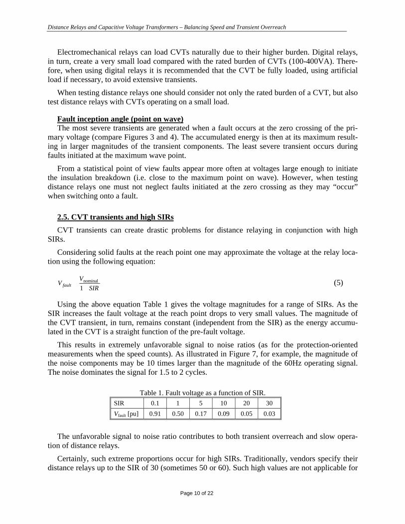
Using the above equation Table 1 gives the voltage magnitudes for a range of SIRs. As theSIR increases the fault voltage at the reach point drops to very small values. The magnitude ofthe CVT transient, in turn, remains constant (independent from the SIR) as the energy accumu-lated in the CVT is a straight function of the pre-fault voltage.
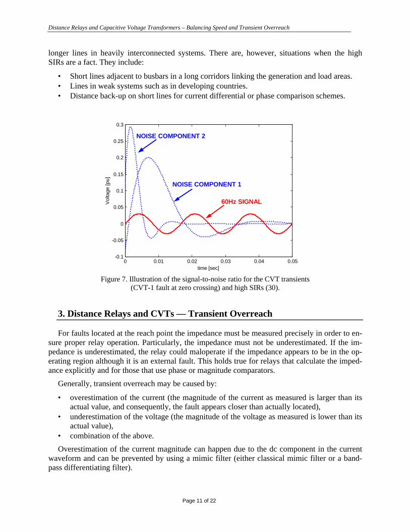
This results in extremely unfavorable signal to noise ratios (as for the protection-orientedmeasurements when the speed counts). As illustrated in Figure 7, for example, the magnitude ofthe noise components may be 10 times larger than the magnitude of the 60Hz operating signal.The noise dominates the signal for 1.5 to 2 cycles.
Table 1. Fault voltage as a function of SIR.SIR 0.1 1 5 10 20 30
Vfault [pu] 0.91 0.50 0.17 0.09 0.05 0.03
The unfavorable signal to noise ratio contributes to both transient overreach and slow opera-tion of distance relays.
Certainly, such extreme proportions occur for high SIRs. Traditionally, vendors specify theirdistance relays up to the SIR of 30 (sometimes 50 or 60). Such high values are not applicable for
Distance Relays and Capacitive Voltage Transformers – Balancing Speed and Transient Overreach
Page 11 of 22
longer lines in heavily interconnected systems. There are, however, situations when the highSIRs are a fact. They include:
• Short lines adjacent to busbars in a long corridors linking the generation and load areas.• Lines in weak systems such as in developing countries.• Distance back-up on short lines for current differential or phase comparison schemes.
0 0.01 0.02 0.03 0.04 0.05-0.1
-0.05
0
0.05
0.1
0.15
0.2
0.25
0.3
time [sec]
Vol
tage
[pu]
NOISE COMPONENT 2
60Hz SIGNAL
NOISE COMPONENT 1
Figure 7. Illustration of the signal-to-noise ratio for the CVT transients(CVT-1 fault at zero crossing) and high SIRs (30).
3. Distance Relays and CVTs — Transient Overreach
For faults located at the reach point the impedance must be measured precisely in order to en-sure proper relay operation. Particularly, the impedance must not be underestimated. If the im-pedance is underestimated, the relay could maloperate if the impedance appears to be in the op-erating region although it is an external fault. This holds true for relays that calculate the imped-ance explicitly and for those that use phase or magnitude comparators.
Generally, transient overreach may be caused by:
• overestimation of the current (the magnitude of the current as measured is larger than itsactual value, and consequently, the fault appears closer than actually located),
• underestimation of the voltage (the magnitude of the voltage as measured is lower than itsactual value),
• combination of the above.
Overestimation of the current magnitude can happen due to the dc component in the currentwaveform and can be prevented by using a mimic filter (either classical mimic filter or a band-pass differentiating filter).
Distance Relays and Capacitive Voltage Transformers – Balancing Speed and Transient Overreach
Page 12 of 22
Underestimation of the voltage can happen due to CVT transients and is much more difficultto control.
3.1. Voltage estimation
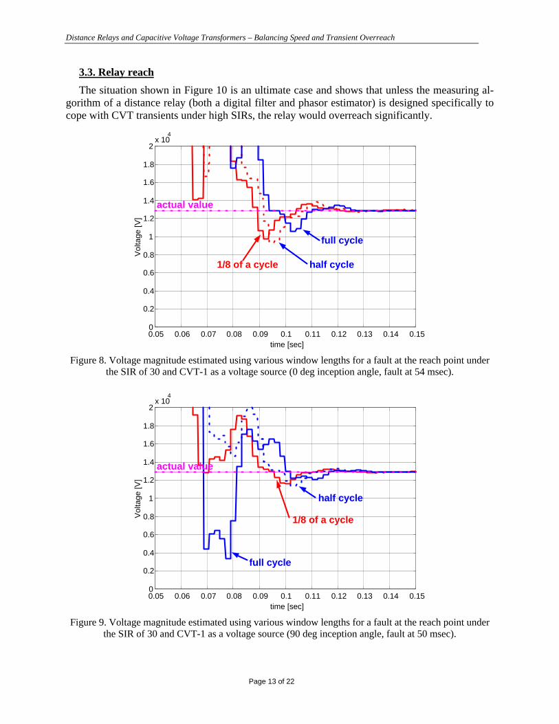
To illustrate the problem Figures 8 and 9 present sample voltage waveforms (CVT-1,SIR=30) and the estimates of the magnitude obtained using the Fourier algorithm with the win-dow of 1/8th of a power cycle, half-, and full-cycle.
Analysis of a large number of simulations similar to the presented samples leads to the fol-lowing observations:
(a) Underestimation of the voltage magnitude can be significant (contributing up to 80-90% ofthe error). Assuming the current magnitude is being measured correctly at the moment whenthe voltage is underestimated, the impedance becomes underestimated proportionally to thevoltage magnitude (80-90% of transient overreach).
(b) Underestimation of the voltage magnitude occurs 20-40msec after the fault initiation. Thismay lead to the idea of introducing security counts (deliberate delay) some time after thefault occurrence to prevent transient overreach. This solution, however, is not robust sincethe danger of transient overreach may occur as early as 20msec – the security counts intro-duced so early would slow down a relay significantly for high SIRs.
(c) At some point in time, the noise or some of its components assume the magnitude close tothe 60Hz voltage but opposite phase (see Figure 7 – the noise component 1 resembles the in-verted 60Hz signal during the 18-25msec time interval). The 60Hz signal and the noise com-ponents cancel mutually to certain extent, and therefore, the phasor estimator tends to under-estimate the magnitude.
(d) Underestimation of the voltage magnitude is independent from the window size of the phasorestimator and the fault inception angle. Unexpectedly, larger errors may occur for long datawindows during less severe transients (see Figure 9). This reinforces the call for thoroughtesting and negates some of the common assumptions that the fault at the zero crossing al-ways causes the most trouble for distance relays, for example.
3.2. Impedance estimation
Underestimation of the voltage magnitude translates directly (assuming the current beingmeasured accurately) into the negative error in the measured impedance — a fault would seem tobe closer.
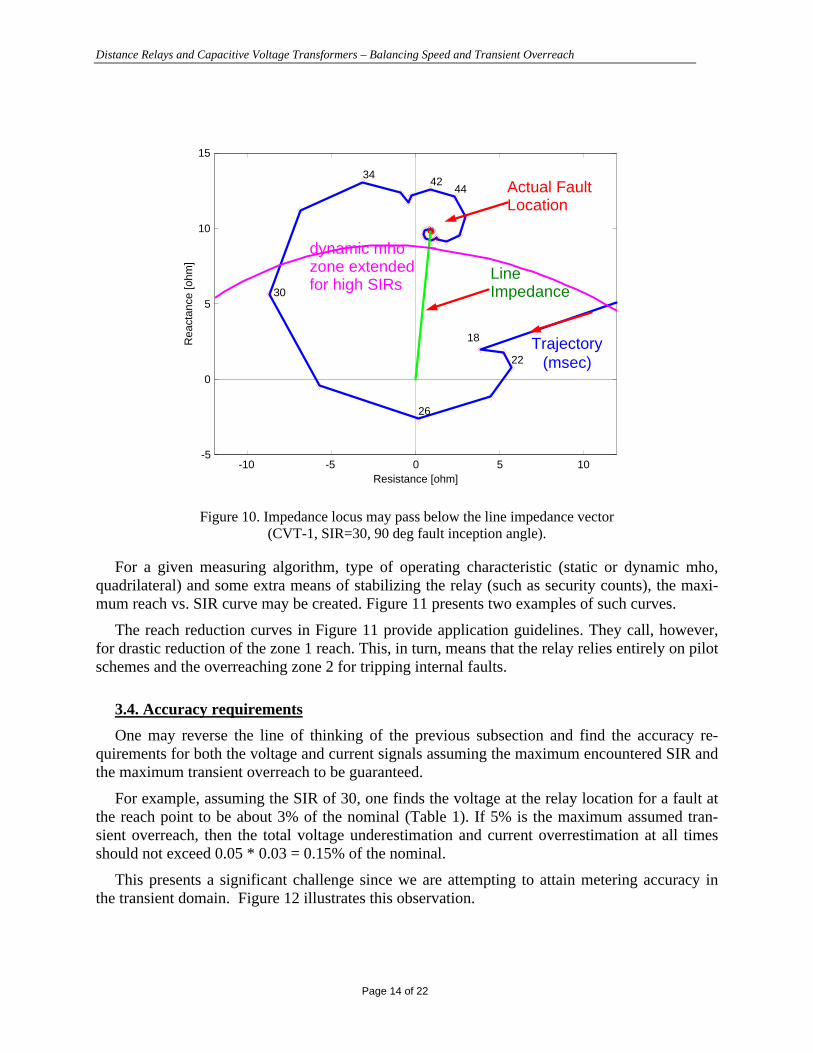
In addition, the phase of the voltage signal may show significant transient errors due to theCVT noise — the phase may flip by 360 degrees before settling to its correct value. This causesthe impedance trajectory to orbit the origin of the Z-plane as shown in Figure 10. This phenome-non is very dangerous for relay stability because even if the impedance is not underestimated bythe magnitude, relays using expanded mho characteristics will maloperate due to the impedanceentering the expanded zone 1 characteristic, especially for high SIRs.
Distance Relays and Capacitive Voltage Transformers – Balancing Speed and Transient Overreach
Page 13 of 22
3.3. Relay reach
The situation shown in Figure 10 is an ultimate case and shows that unless the measuring al-gorithm of a distance relay (both a digital filter and phasor estimator) is designed specifically tocope with CVT transients under high SIRs, the relay would overreach significantly.
0.05 0.06 0.07 0.08 0.09 0.1 0.11 0.12 0.13 0.14 0.150
0.2
0.4
0.6
0.8
1
1.2
1.4
1.6
1.8
2x 10
4V
olta
ge [V
]
time [sec]
1/8 of a cycle
full cycle
half cycle
actual value
Figure 8. Voltage magnitude estimated using various window lengths for a fault at the reach point underthe SIR of 30 and CVT-1 as a voltage source (0 deg inception angle, fault at 54 msec).
0.05 0.06 0.07 0.08 0.09 0.1 0.11 0.12 0.13 0.14 0.150
0.2
0.4
0.6
0.8
1
1.2
1.4
1.6
1.8
2x 10
4
Vol
tage
[V]
time [sec]
1/8 of a cycle
full cycle
half cycle
actual value
Figure 9. Voltage magnitude estimated using various window lengths for a fault at the reach point underthe SIR of 30 and CVT-1 as a voltage source (90 deg inception angle, fault at 50 msec).
Distance Relays and Capacitive Voltage Transformers – Balancing Speed and Transient Overreach
Page 14 of 22
-10 -5 0 5 10-5
0
5
10
15
Rea
ctan
ce [o
hm]
Resistance [ohm]
18
22
26
30
3442
44 Actual FaultLocation
LineImpedance
Trajectory(msec)
dynamic mhozone extendedfor high SIRs
Figure 10. Impedance locus may pass below the line impedance vector(CVT-1, SIR=30, 90 deg fault inception angle).
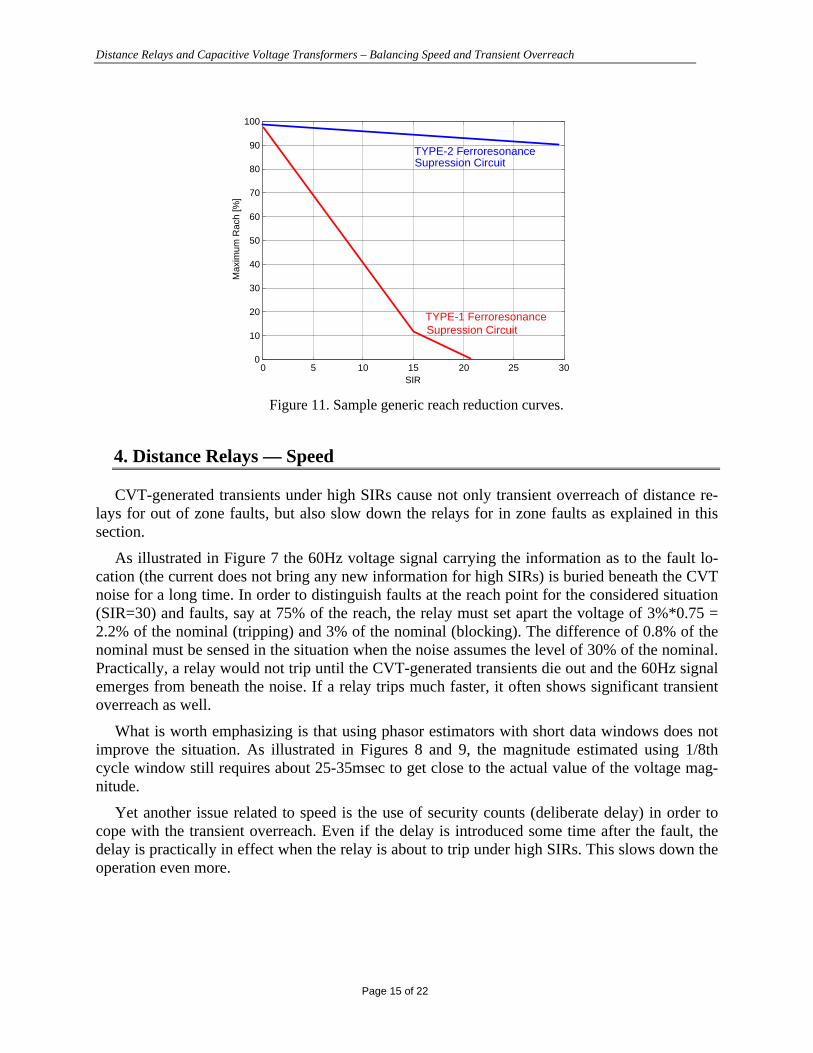
For a given measuring algorithm, type of operating characteristic (static or dynamic mho,quadrilateral) and some extra means of stabilizing the relay (such as security counts), the maxi-mum reach vs. SIR curve may be created. Figure 11 presents two examples of such curves.
The reach reduction curves in Figure 11 provide application guidelines. They call, however,for drastic reduction of the zone 1 reach. This, in turn, means that the relay relies entirely on pilotschemes and the overreaching zone 2 for tripping internal faults.
3.4. Accuracy requirements
One may reverse the line of thinking of the previous subsection and find the accuracy re-quirements for both the voltage and current signals assuming the maximum encountered SIR andthe maximum transient overreach to be guaranteed.
For example, assuming the SIR of 30, one finds the voltage at the relay location for a fault atthe reach point to be about 3% of the nominal (Table 1). If 5% is the maximum assumed tran-sient overreach, then the total voltage underestimation and current overrestimation at all timesshould not exceed 0.05 * 0.03 = 0.15% of the nominal.
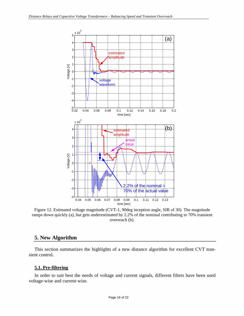
This presents a significant challenge since we are attempting to attain metering accuracy inthe transient domain. Figure 12 illustrates this observation.
Distance Relays and Capacitive Voltage Transformers – Balancing Speed and Transient Overreach
Page 15 of 22
0 5 10 15 20 25 300
10
20
30
40
50
60
70
80
90
100
Max
imum
Rac
h [%
]
SIR
TYPE-2 FerroresonanceSupression Circuit
TYPE-1 FerroresonanceSupression Circuit
Figure 11. Sample generic reach reduction curves.
4. Distance Relays — Speed
CVT-generated transients under high SIRs cause not only transient overreach of distance re-lays for out of zone faults, but also slow down the relays for in zone faults as explained in thissection.
As illustrated in Figure 7 the 60Hz voltage signal carrying the information as to the fault lo-cation (the current does not bring any new information for high SIRs) is buried beneath the CVTnoise for a long time. In order to distinguish faults at the reach point for the considered situation(SIR=30) and faults, say at 75% of the reach, the relay must set apart the voltage of 3%*0.75 =2.2% of the nominal (tripping) and 3% of the nominal (blocking). The difference of 0.8% of thenominal must be sensed in the situation when the noise assumes the level of 30% of the nominal.Practically, a relay would not trip until the CVT-generated transients die out and the 60Hz signalemerges from beneath the noise. If a relay trips much faster, it often shows significant transientoverreach as well.
What is worth emphasizing is that using phasor estimators with short data windows does notimprove the situation. As illustrated in Figures 8 and 9, the magnitude estimated using 1/8thcycle window still requires about 25-35msec to get close to the actual value of the voltage mag-nitude.
Yet another issue related to speed is the use of security counts (deliberate delay) in order tocope with the transient overreach. Even if the delay is introduced some time after the fault, thedelay is practically in effect when the relay is about to trip under high SIRs. This slows down theoperation even more.
Distance Relays and Capacitive Voltage Transformers – Balancing Speed and Transient Overreach
Page 16 of 22
0.02 0.04 0.06 0.08 0.1 0.12 0.14 0.16 0.18 0.2-5
-4
-3
-2
-1
0
1
2
3
4
5x 10
5
Vol
tage
[V]
time [sec]
voltagewaveform
estimatedamplitude
(a)
0.04 0.05 0.06 0.07 0.08 0.09 0.1 0.11 0.12 0.13-4
-3
-2
-1
0
1
2
3
4
x 104
Vol
tage
[V]
time [sec]
estimatedamplitude
(b)
actualvalue
2.2% of the nominal = 70% of the actual value
Figure 12. Estimated voltage magnitude (CVT-1, 90deg inception angle, SIR of 30). The magnituderamps down quickly (a), but gets underestimated by 2.2% of the nominal contributing to 70% transient
overreach (b).
5. New Algorithm
This section summarizes the highlights of a new distance algorithm for excellent CVT tran-sient control.
5.1. Pre-filtering
In order to suit best the needs of voltage and current signals, different filters have been usedvoltage-wise and current-wise.

Distance Relays and Capacitive Voltage Transformers – Balancing Speed and Transient Overreach
Page 17 of 22
The currents are pre-filtered using a “modified mimic” filter. The filter is a stationary FiniteImpulse Response (FIR) filter which has a much better frequency response compared to the clas-sical mimic filter.
The voltages are pre-filtered using a special, designed to cope with CVT transients, non-symmetrical FIR filter with the window length of approximately 3/2nd of a power cycle. Due toits optimal design, the delay introduced by the filter is much lower than a power cycle. The filterperforms very well for both CVT transients and high frequency noise.
5.2. Phasor estimation
Likewise, different phasor estimators are used for the voltage and current signals. The currentphasors are measured using the full-cycle Fourier algorithm. The voltage phasors are estimatedusing the half-cycle Fourier algorithm.
The combination of the pre-filtering and phasor estimation algorithms ensures the followingaccuracy:
• Currents: less than 3% transient overshoot due to the dc components.• Voltages: less than 0.6% (of the nominal) transient underestimation due to the CVT tran-
sients.
The combination of the above accuracy result in transient overreach ranging from 1% (forSIRs up to 5) to about 20% (SIR = 30).
In order to reduce the transient overreach further, a double zone 1 has been implemented asshown in Figure 13.
DelayedTrip
InstantaneousTrip
R
X
Figure 13. Instantaneous and delayed zones 1.
The inner zone 1 has its reach dynamically adjusted using the voltage magnitude. The dy-namic reach varies from 80% of the actual (set) reach for the SIR of 30, up to 95% for the SIR of0.1. The inner zone is completely secure and therefore no delay is applied there. It ensures fast
Distance Relays and Capacitive Voltage Transformers – Balancing Speed and Transient Overreach
Page 18 of 22
operation for faults located at 0-80% of the reach for high SIRs, and for 0-95% of the reach forlow SIRs.
The outer zone 1 has its reach fixed at 100% of the actual (reach setting) and applies somedelay to prevent maloperation.
As a result, the transient overreach has been reduced to a very small value (~1-5% over theSIRs up to 30) at the expense of slowing down the relay only for faults close to the reach point.
5.3. Distance comparators
Let us use the mho characteristic to illustrate the concept of double-reach zone 1 in more de-tail. The mho distance element uses dynamic (memory polarized) characteristics with “self-tilting” reactance and memory-polarized zero- and negative-sequence directional supervision.
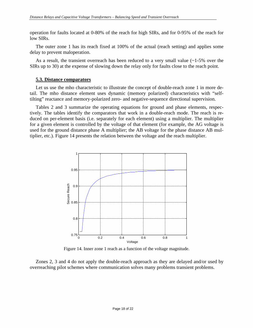
Tables 2 and 3 summarize the operating equations for ground and phase elements, respec-tively. The tables identify the comparators that work in a double-reach mode. The reach is re-duced on per-element basis (i.e. separately for each element) using a multiplier. The multiplierfor a given element is controlled by the voltage of that element (for example, the AG voltage isused for the ground distance phase A multiplier; the AB voltage for the phase distance AB mul-tiplier, etc.). Figure 14 presents the relation between the voltage and the reach multiplier.
0 0.2 0.4 0.6 0.8 10.75
0.8
0.85
0.9
0.95
1
Secu
re R
each
Voltage
Figure 14. Inner zone 1 reach as a function of the voltage magnitude.
Zones 2, 3 and 4 do not apply the double-reach approach as they are delayed and/or used byoverreaching pilot schemes where communication solves many problems transient problems.

Distance Relays and Capacitive Voltage Transformers – Balancing Speed and Transient Overreach
Page 19 of 22
Table 2. Ground distance elements.
Characteristic Phase Comparator Double Reach (Y/N)
Dynamic mho IZ-V vs. Vmem (pos) Y
Reactance IZ-V vs. I0Z Y
Zero-sequence directional I0Z vs. Vmem (pos) N
Negative-sequence directional I2Z vs. Vmem (pos) N
Table 3. Phase distance elements.
Characteristic Phase Comparator Double Reach (Y/N)
Dynamic mho IZ-V vs. Vmem (pos) Y
Reactance IZ-V vs. IZ Y
Directional IZ vs. Vmem (pos) N
5.4. Hardware implementation
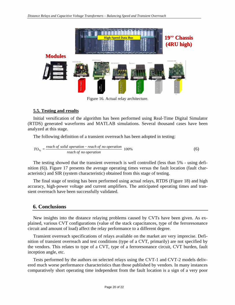
The described algorithm has been implemented using the concept of a “universal relay” — amodular, scaleable and upgradable engine for protective relaying. Figure 15 presents the basichardware modules of the relay; while Figure 16 — the actual implementation.
High-Speed Data BusHigh-Speed Data Bus
Pow
er S
uppl
yP
ower
Sup
ply
CP
UC
PU
Mai
n P
roce
ssor
Mai
n P
roce
ssor
DSP
& M
agne
tics
DSP
& M
agne
tics
DS
P p
roce
ssor
+ C
T/V
Ts
DS
P p
roce
ssor
+ C
T/V
Ts
DIG
ITA
L I
/OD
IGIT
AL
I/O
Sta
tus
Inpu
ts /
Con
trol
Ou
tpu
tsS
tatu
s In
puts
/ C
ontr
ol O
utp
uts
AN
AL
OG
I/O
AN
AL
OG
I/O
An
alog
Tra
nsd
uce
r I/
OA
nal
og T
ran
sdu
cer
I/O
CO
MM
UN
ICA
TIO
NS
CO
MM
UN
ICA
TIO
NS
(Eth
ern
et, H
DL
C, U
AR
T)
(Eth
ern
et, H
DL
C, U
AR
T)
DisplayDisplayDisplay
KeypadKeypadKeypad
LEDModules
LEDLEDModulesModules
LEDModules
LEDLEDModulesModules
LEDModules
LEDLEDModulesModules
Modular HMI PanelModular HMI Panel
Figure 15. Modular hardware architecture.
Distance Relays and Capacitive Voltage Transformers – Balancing Speed and Transient Overreach
Page 20 of 22
19’’ Chassis19’’ Chassis(4RU high)(4RU high)
Pow
er S
uppl
yP
ower
Sup
ply
CP
UC
PU
Mai
n P
roce
ssor
Mai
n P
roce
ssor
DSP
& M
agne
tics
DSP
& M
agne
tics
DS
P p
roce
ssor
+ C
T/V
Ts
DS
P p
roce
ssor
+ C
T/V
Ts
DIG
ITA
L I
/OD
IGIT
AL
I/O
Sta
tus
Inpu
ts /
Con
trol
Ou
tpu
tsS
tatu
s In
puts
/ C
ontr
ol O
utp
uts
AN
AL
OG
I/O
AN
AL
OG
I/O
An
alog
Tra
nsd
uce
r I/
OA
nal
og T
ran
sdu
cer
I/O
CO
MM
UN
ICA
TIO
NS
CO
MM
UN
ICA
TIO
NS
(Eth
ern
et, H
DL
C, U
AR
T)
(Eth
ern
et, H
DL
C, U
AR
T)
High-Speed Data BusHigh-Speed Data Bus
ModulesModules
Figure 16. Actual relay architecture.
5.5. Testing and results
Initial versification of the algorithm has been performed using Real-Time Digital Simulator(RTDS) generated waveforms and MATLAB simulations. Several thousand cases have beenanalyzed at this stage.
The following definition of a transient overreach has been adopted in testing:
%100% ⋅−
=operationnoofreach
operationnoofreachoperationsolidofreachTO (6)
The testing showed that the transient overreach is well controlled (less than 5% - using defi-nition (6)). Figure 17 presents the average operating times versus the fault location (fault char-acteristic) and SIR (system characteristic) obtained from this stage of testing.
The final stage of testing has been performed using actual relays, RTDS (Figure 18) and highaccuracy, high-power voltage and current amplifiers. The anticipated operating times and tran-sient overreach have been successfully validated.
6. Conclusions
New insights into the distance relaying problems caused by CVTs have been given. As ex-plained, various CVT configurations (value of the stack capacitances, type of the ferroresonancecircuit and amount of load) affect the relay performance to a different degree.
Transient overreach specifications of relays available on the market are very imprecise. Defi-nition of transient overreach and test conditions (type of a CVT, primarily) are not specified bythe vendors. This relates to type of a CVT, type of a ferroresonance circuit, CVT burden, faultinception angle, etc.
Tests performed by the authors on selected relays using the CVT-1 and CVT-2 models deliv-ered much worse performance characteristics than those published by vendors. In many instancescomparatively short operating time independent from the fault location is a sign of a very poor

Distance Relays and Capacitive Voltage Transformers – Balancing Speed and Transient Overreach
Page 21 of 22
CVT transient control under high SIRs. In response to that, a new algorithm has been presentedin this paper that ensures superior performance in terms of transient overreach without signifi-cant sacrificing the speed of operation.
0 10 20 30 40 50 60 70 800.4
0.6
0.8
1
1.2
1.4
1.6
1.8
2
2.2
2.4
Ave
rage
tim
e (c
ycle
s)
X/Xm (%)
SIR=1
SIR=3
SIR=5
SIR=20
SIR=15
SIR=10
SIR=30
SIR=0.1
10-1
100
101
102
0
20
40
60
805
10
15
20
25
30
35
40
SIRX/Xm
Ave
rage
tim
e
SIR
X/X
m
10 15
15
20
20
20
25
25
25
25
30
30
10-1
100
101
10
20
30
40
50
60
70
Figure 17. Average operating times of the new algorithm (MATLAB).

Distance Relays and Capacitive Voltage Transformers – Balancing Speed and Transient Overreach
Page 22 of 22
Figure 18. RTDS hardware used in testing.
v v v
Biographies
Bogdan Kasztenny received his M.Sc. (89) and Ph.D. (92) degrees (both with honors) from the Wroclaw Univer-sity of Technology (WUT), Poland. In 1989 he joined the Department of Electrical Engineering of WUT. In 1994 hewas with Southern Illinois University in Carbondale as a Visiting Assistant Professor. From 1994 till 1997 he wasinvolved in applied research for Asea Brown Boveri in the area of transformer and series compensated line protec-tion. During the academic year 1997/98 Dr.Kasztenny was with Texas A&M University as a Senior Fulbright Fel-low, and then, till 1999 - as a Visiting Assistant Professor. Currently, Dr.Kasztenny works for General ElectricCompany as a Senior Application/Invention Engineer. Dr.Kasztenny is a Senior Member of IEEE, holds 2 patents,and has published more than 90 technical papers.
Dave Sharples after early experience with the Electricity Authority in the UK graduated from the University ofManchester (UK) with a M.Sc. (Tech) degree in 1963. After experience with the English Electric Meter Relay andInstrument Division he emigrated to Canada to join Ontario Hydro. Following early retirement in 1993 he has actedas a protection consultant, most recently with GE Power Management.
Vince Asaro graduated from Ryerson Polytechnical Institute, Toronto, Ontario Canada, in 1988 with a Bachelor ofElectrical Engineering Technology specializing in control systems. He then worked for Perkin Elmer Photovac de-signing hardware and firmware for gas analytical equipment. . In 1997 he joined General Electric - Power Manage-ment and is now the lead firmware designer for the D60 distance relay and is responsible for firmware developmentfor new products.
Marzio Pozzuoli graduated from Ryerson Polytechnical Institute, Toronto, Ontario Canada, in 1987 with a Bachelorof Electrical Engineering Technology specializing in control systems. He then worked for Johnson Controls design-ing industrial automation systems. He was involved in the design of Partial Discharge Analysis systems for largerotating electric machinery with FES International. In 1994 he joined General Electric – Power Management and isthe Technology Manager responsible for the engineering and development of new products.
Top Related