


Languages
Pages
Legal


Degree's Final Project
Bachelor's Degree in Industrial Technology Engineering
Development of a Python application for
monitoring RF messages using one NRF24L01
board and a USB-MPSSE cable
REPORT
Author: Joan Ràfols Bellés Directors/s: Juan Manuel Moreno Eguilaz Call: June 2016
School of Industrial Engineering of
Barcelona

Development of a Python application for monitoring RF messages using one NRF24L01 board and a USB-MPSSE cable 1
Summary
The objective of this project is to build a python application to monitor radiofrequency (RF) packets
on a personal computer (PC). In order to do this, a NRF24L01 board will be used together with a
USB-MPSSE cable to connect the board with the PC. This system attempts to replicate a sniffer
functionality, capable of receiving packets from different transmitters with very little information
from their configuration. This functionality, which goes beyond regular packet reception, allows
the user not only to catch messages from transmitters with little information of their configurations
but also to provide message monitoring from devices with different configurations at the same
time.
This report attempts to give the reader a progressive introduction to RF communications starting
from a basic communication mode in which regular messages are sent and received throughout
the NRF24L01 and ending with a far more complex mode where the application catches the
packets just by knowing the first 3 bytes from their address, no matter how long it is and also
without knowing the CRC length. Then it will not only extract the message from the unknown
packet but also predict the transmitters configuration and configure the receiver accordingly to
optimize the reception of the following packets.
None of these latter functionalities are provided by the NRF24L01 itself. Therefore, this project
presents a software based enhancement of the NRF24L01 possibilities, extending these chip
processing capabilities to the PC processor.
In addition, a deep insight into the Graphic User Interface creation is given coupled with the
interaction of some basic libraries that have been adapted to meet these project necessities.
Two examples of these functionality extensions have been implemented in the application and
are detailed in this report. These are: Fast file download and Focus.
Finally, this report explains the conversion of the python application into an executable file for
Windows, meaning that this application can be executed in every Microsoft Windows OS without
requiring neither python or any of its modules installation.

2 Report

Development of a Python application for monitoring RF messages using one NRF24L01 board and a USB-MPSSE cable 3
Index
SUMMARY ____________________________________________________ 0
INDEX ________________________________________________________ 3
ANNEX _______________________________________________________ 6
1. GLOSSARY _______________________________________________ 7
2. INTRODUCTION ___________________________________________ 8
2.1. Objectives ...........................................................................................................8
2.2. Scope ..................................................................................................................9
2.3. Overview .............................................................................................................9
3. HARDWARE _____________________________________________ 11
3.1. nRF24L01+ board ........................................................................................... 11
3.2. USB Hi-Speed – MPSSE Cable (C232HM-DDHSL-0) ................................. 11
3.3. Connections ..................................................................................................... 12
4. SOFTWARE STRUCTURE __________________________________ 16
5. LIBRARIES ______________________________________________ 17
5.1. First level classes: ftdi and SPI ....................................................................... 17
5.2. Second level class NRF24L01 ....................................................................... 19
6. GUI _____________________________________________________ 22
6.1. Title bar ............................................................................................................ 24
6.2. Minimize and close buttons............................................................................. 24
6.3. Labels, input fields and output fields .............................................................. 25
6.4. Status bar ......................................................................................................... 25
7. APP.PY FILE _____________________________________________ 26
7.1. GeneralModeFunctions class ......................................................................... 26
7.1.1. Inheritance........................................................................................................... 26
7.1.2. Methods ............................................................................................................... 27
7.1.2.1. listening() ............................................................................................... 27
7.1.2.2. stop_listening() ...................................................................................... 27
7.1.2.3. end_Get_CheckConnection() ............................................................... 27
7.1.2.4. add_to_record(s) ................................................................................... 27
7.1.2.5. Change_mode() .................................................................................... 28
7.2. QThread classes ............................................................................................. 28
4 Report
7.2.1. Intro class ............................................................................................................. 28
7.2.2. Move class ........................................................................................................... 29
7.2.3. GetConnection class ........................................................................................... 29
7.2.3.1. Checkconnection class ............................................................................ 30
7.2.4. ListeningLoop class ............................................................................................. 30
7.2.5. PacketValidation class ......................................................................................... 31
7.3. Manual mode ................................................................................................... 31
7.3.1. ManualMode class ............................................................................................... 34
7.3.1.1. The constructor ........................................................................................ 34
7.3.1.2. apply_new_parameters() method ........................................................... 35
7.3.1.3. read() method .......................................................................................... 35
7.3.1.4. tx_message() method .............................................................................. 35
7.3.1.5. sending() method ..................................................................................... 35
7.3.2. Example ............................................................................................................... 35
7.4. Multireceiving mode ........................................................................................ 41
7.4.1. Multireceiving_mode class .................................................................................. 41
7.4.1.1. apply_new_parameters() ......................................................................... 41
7.4.1.2. read() ........................................................................................................ 43
7.4.2. Example ............................................................................................................... 44
7.5. Automatic mode ............................................................................................... 47
7.5.1. Enhanced ShockBurst packet ............................................................................. 48
7.5.2. Receiving process ............................................................................................... 48
7.5.3. CRC ...................................................................................................................... 50
7.5.3.1. CRC manual calculation .......................................................................... 51
7.5.4. Message extraction.............................................................................................. 53
7.5.5. PID. Avoiding retransmissions ............................................................................ 54
7.5.6. First try-outs ......................................................................................................... 55
7.5.7. Automatic_mode class ........................................................................................ 57
7.5.7.1. apply_new_parameters ........................................................................... 57
7.5.7.2. read() ........................................................................................................ 59
7.5.7.3. packet_validation class ............................................................................ 59
7.5.7.4. filter_duplicities() ...................................................................................... 59
7.5.8. Example ............................................................................................................... 59
7.5.9. Extra functionalities .............................................................................................. 61
7.5.9.1. Fast file download .................................................................................... 61
7.5.9.2. Focus........................................................................................................ 63

Development of a Python application for monitoring RF messages using one NRF24L01 board and a USB-MPSSE cable 5
7.6. Tests................................................................................................................. 64
7.6.1. Manual mode ...................................................................................................... 64
7.6.2. Multireceiving mode: ........................................................................................... 67
7.6.3. Automatic mode .................................................................................................. 69
8. COMPATIBILITY __________________________________________ 72
9. FUTURE WORKS _________________________________________ 73
10. ENVIRONMENTAL FOOTPRINT _____________________________ 74
11. COSTS AND TIME PLANNING ______________________________ 75
CONCLUSIONS _______________________________________________ 76
BIBLIOGRAPHY ______________________________________________ 77
Figures ....................................................................................................................... 78
6 Report
Annexes
A. APPLICATION’S CODE _____________________________________ 1
A.1. first_level_class.py ............................................................................................. 1
A.2. second_level_class.py....................................................................................... 7
A.3. app.py ............................................................................................................... 14
A.4. manual_mode.py ............................................................................................. 30
A.5. multireceiving_mode.py ................................................................................... 38
A.6. automatic_mode.py ......................................................................................... 46
A.7. CRC.py ............................................................................................................. 54
B. FIRST_LEVEL_CLASS.PY DOCUMENTATION SCREENSHOTS ___ 57
C. PACKET SENDING - MANUAL MODE CODE___________________ 59
D. PACKET SENDING – AUTOMATIC/MULTIRECEIVING MODE
CODE ___________________________________________________ 81
E. FILE SENDING CODE ______________________________________ 85
E.1. File converter ................................................................................................... 85
E.2. C files to send the file ...................................................................................... 85
F. KEYBOARD SENDING CODE _______________________________ 91
G. CRC FULL CALCULATION _________________________________ 98
Development of a Python application for monitoring RF messages using one NRF24L01 board and a USB-MPSSE cable 7
1. Glossary
DI/DO: Data In/Out.
C232HM-DDHSL-0: USB Hi-Speed – MPSSE Cable’s reference.
CE: Chip enable.
CSN: Chip Select (active low).
GND: Ground.
GPIOL: General Purpose Input/Output.
GUI: Graphic User Interface.
JTAG: Joint Test Action Group.
MCU: Microcontroller Unit.
MISO: Master In Slave Out.
MOSI: Master Out Slave In.
MPSSE: Multi-Protocol Synchronous Serial Engine.
RF: Radio Frequency.
SCK/SK: Serial Clock.
SPI: Serial Peripheral Interface.
VCC: Collector to Collector Voltage.
CRC: Circuit redundancy check.
SAR: Specific energy absorption rate.

8 Report
2. Introduction
This project arises from the necessity of the Electronic Engineering Department from ETSEIB –
UPC to have a low cost device to monitor RF communications. This device permits to catch
packets with different configurations and provide feedback in order to fix any problem that may
occur. Moreover, this project can be used as a learning tool for the students to understand how
the communication works and what is the roll of every part of the packet structure.
2.1. Objectives
Although there are some inevitable hardware items inherent to the project that need to be tackled,
fundamentally, this is a software development based project. The main objective is to develop a
GUI application which, together with a couple of low cost devices, can replicate the functionality
of a RF sniffer. In order to achieve that goal, the project needs to get through several stages
including:
The development of a python library to access SPI hardware.
The development of a python library to communicate with a nRF24L01 board, that means,
being able to configure the chip as well as to send and receive data.
The manual implementation of a “Promiscuous reception” mode, which provides the
sniffer with the possibility of tracking several addresses at a time.
Take profit of this “Promiscuous reception” and the Enhanced Shockburst packet to use
the CRC in order to get the message with no more information from the transmitted packet
than the first 3 bytes of the address and the working frequency.
Upon these libraries, build a python GUI application which prevents the user from any
contact with neither the python code nor the python terminal (that means, no programming
notions required) as well as providing a windows .exe file so that the user can use this
app in almost any computer.
Keep record of the device configuration and all the packet transaction done in the last use
of the application and save it in a text file.

Development of a Python application for monitoring RF messages using one NRF24L01 board and a USB-MPSSE cable 9
2.2. Scope
This project does not contain a detailed explanation of all the characteristics of the hardware
devices. As mentioned before, this is a software development based project. Therefore, only the
necessary information to understand how the program works will be covered.
This project contains a detailed insight into programing procedures and the RF package
communication.
2.3. Overview
This project consists in the development of GUI (Graphic User Interface) application to control a
NRF24L01 board. This board is capable of both receiving and transmitting RF (Radiofrequency)
packets from other boards and is connected to the PC via USB cable. The whole system will be
named sniffer, which is able to catch and analyse packets sent by other NRF24L01 boards.
The application is divided in three different modes. Three different ways of configuring the board
in order to obtain different functionalities. Their sequential development permits the following
mode to soak up all the experience acquired in the previous one.
The first one is called Manual mode and it could be seen as an introduction to the NRF24L01
basic procedures such as changing registers and sending/receiving messages.
The second one, Multireceiving mode, is a previous stage before moving on to the complexity of
the last mode. It allows the sniffer to receive packets from different addresses, which typically
corresponds to different transmitters. Moreover, this mode gives information about the address
from which every message comes from.
Up to this point, it can be easily noticed that it is all about changing registers. Nevertheless, the
third mode, Automatic mode, takes this project into a whole new level of complexity where the
NRF24L01 functionalities are insufficient and a few smart plays are needed so that the board can
do the trick. The chief aim of this mode is to implement the so called “Promiscuous reading”, which
means receiving packets without knowing the last bytes of the address. However, it was
acknowledged that this mode did not deserve its name, since the user should still introduce some
NRF24L01 parameters (apart from a partial address and the frequency) that made this mode not
even close to being automatic. Not before acquiring a deep knowledge of the packet structure, a
solution to this problem could be found. A glimmer of hope was delivered to this mode when the

10 Report
enormous potential of the CRC was discovered. The CRC is a one or two bytes’ code, located at
the very end of the packet, that is calculated over the whole packet. Although it could seem a
minor element within the packet structure, it provided a lot of room for improvement allowing this
mode to just give as parameters the first 3 bytes from the address (no matter its total length) and
the working frequency in order to extract the message and important information about the
transmitters configuration. It should be noted that the board is incapable of processing a packet
in that way, therefore it has been configured to just store as much bytes as possible in its FIFO
(First In First Out) after receiving the first 3 bytes from the address. This permitted catching
packets and being able to process them (this is message, CRC length, PID and full address
extraction) out of the NRF24L01 which gives the application free rein to work with that bunch of
bits. Obviously, this enhancement of capabilities did not come at any cost. Reducing the address
length results in more noise being captured which couple with a slower message extraction
became a problem when sending large packets. Many measures were taken in that sense, such
as the CRC calculation function optimization and a multithreading programming structure. Both
actions increased considerably the processing speed. Not satisfied with that, two more
functionalities were implemented taking the flexibility of an Automatic mode, and the processing
speed of a standard packet reception. How this is achieved will be explained at length in this
report.
It is also worth mentioning that great efforts have been devoted into GUI development in an
attempt to stand out among the basic Window’s window giving this app a personalised and
professional outfit.
Finally, the reader can complement this report with an exhaustive documentation over all the
classes and methods that this application contains which is available on the CD and in many links
within this report. This documentation has been built with sphinx. Annex B provides screenshots
regarding the first_level_class.py file as an example.

Development of a Python application for monitoring RF messages using one NRF24L01 board and a USB-MPSSE cable 11
3. Hardware
There are 3 devices involving this project which allow the design of a radio system through which
communication with other devices can be established. These are the followings:
The nRF24L01+ Single Chip 2.4GHz Transceiver (NRF24L01 board) [1]
A USB Hi-Speed – MPSSE Cable (C232HM-DDHSL-0) [2]
A personal computer
3.1. nRF24L01+ board
This NRF24L01 board is able to both transmit and receive RF data. It simply needs an MCU to
start working. The communication between the computer and the nRF24L01 board is established
through a Serial Peripheral interface (SPI). This chip is compatible with Enhanced ShockBurst,
which is, according to the datasheet [1], “a packet based data link layer that features automatic
packet assembly and timing, automatic acknowledgement and retransmissions of packets”. All
the content the reader needs to know in order to understand this project is fully covered in the
datasheet mentioned before.
3.2. USB Hi-Speed – MPSSE Cable (C232HM-DDHSL-0)
This cable is able to transmit the data sent by the computer through a USB port into the
Fig. 3.1 nRF24L01 RF Board (B). Source: http://www.waveshare.com
dshttp://www.waveshare.com/product/nrf24l01-rf-board-b.htm
http://www.waveshare.com/product/nrf24l01-rf-board-b.htm
http://www.waveshare.com/product/nrf24l01-rf-board-b.htm
http://www.waveshare.com/product/nrf24l01-rf-board-b.htm

12 Report
nRF24L01+ and vice versa, acting as a link between them. Although it is not of paramount
importance for this project, the datasheet [2] covers every characteristic and functionality
regarding this device.
3.3. Connections
NRF24L01 pins:
MPSSE Cable Connections:
Fig. 3.2 USB Hi-Speed – MPSSE Cable. Source: www.ftdichip.com.
Fig. 3.3 NRF24L01 RF Board (B) Pin Definition. Source: www.waveshare.com.

Development of a Python application for monitoring RF messages using one NRF24L01 board and a USB-MPSSE cable 13
The cable description as shown in Fig. 3.4 can be found in this cable datasheet [2]. It is important
to draw attention to the fact that although the figure uses JTAG nomenclature, the SPI interface
will be used for this project, which is displayed in the datasheet [2] as well.
Table 3.1 represents the connections that will be used over the whole project:
NRF24L01 MPSSE Cable
CE GPIOL1 - Purple
SCK SK - Orange
CSN CS - Brown
MOSI DO - Yellow
MISO DI - Green
GND GND – Black
VCC VCC – Red
Fig 3.4 C232HM MPSSE Cable Connections (JTAG nomenclature). Source: www.ftdichip.com.
Table 3.1 NRF24L01 – MPSSE Cable connections. Own source.
14 Report
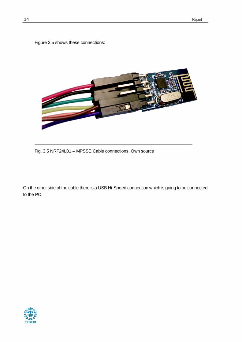
Figure 3.5 shows these connections:
On the other side of the cable there is a USB Hi-Speed connection which is going to be connected
to the PC.
Fig. 3.5 NRF24L01 – MPSSE Cable connections. Own source

Development of a Python application for monitoring RF messages using one NRF24L01 board and a USB-MPSSE cable 15
Fig. 3.7 shows the whole sniffer (NRF24L01 + USB Hi-Speed – MPSSE cable + PC):
Fig. 3.6 USB Hi-Speed - PC connection. Own source.
Fig. 3.7 Sniffer hardware. Own source

16 Report
4. Software structure
This project has been designed with a structure based on software layers, as shown in Fig. 3.8.
It covers from the libraries upon which the whole program is sustained to the GUI and all of its
elements that allow eventually the interaction between the user and the NRF24L01.
The whole project consists of 7 python files. The following diagram provides a clear vision of the
relationships between this files and its classes:
Note there are a few files which support the app.py file such as the GUI and the CRC files, that
do not inherit from the first or second level classes. This report will cover from the base to the top
of the shown software pyramid.
3 main
classes
Total: 11 classes
NRF24L01
SPI
ftdi
Fig. 3.8 Software structure. Own source.
first_level_class.py
second_level_class.py
GUI files:
manual_mode.py
automatic_mode.py
multireceiving_mode.py
CRC file: CRC.py
app.py
ManualMode
AutomaticMode
MultireceivingMode
Development of a Python application for monitoring RF messages using one NRF24L01 board and a USB-MPSSE cable 17
5. Libraries
This section presents the libraries that have been taken from other authors [3, 4] and have been
modified and optimized to fit the needs of this project.
5.1. First level classes: ftdi and SPI
These two classes [3], once have been adequately modified (annex A.1), are able to transmit and
receive data through the FTDI cable. However, it is important to take into account that these
classes were not built to support communication with a NRF24L01. In fact, they were only able to
detect the cable and read registers. Moreover, module d2xx needs to be installed.
The most important elements of these classes are the read and write methods from SPI class.
Almost every method in this file lives to eventually support these two functions. Therefore, it is
necessary to understand how they work.
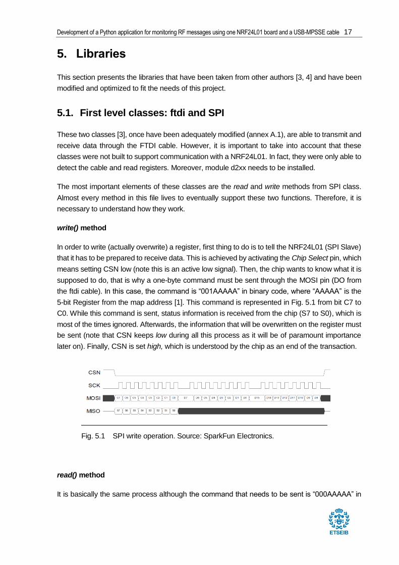
write() method
In order to write (actually overwrite) a register, first thing to do is to tell the NRF24L01 (SPI Slave)
that it has to be prepared to receive data. This is achieved by activating the Chip Select pin, which
means setting CSN low (note this is an active low signal). Then, the chip wants to know what it is
supposed to do, that is why a one-byte command must be sent through the MOSI pin (DO from
the ftdi cable). In this case, the command is “001AAAAA” in binary code, where “AAAAA” is the
5-bit Register from the map address [1]. This command is represented in Fig. 5.1 from bit C7 to
C0. While this command is sent, status information is received from the chip (S7 to S0), which is
most of the times ignored. Afterwards, the information that will be overwritten on the register must
be sent (note that CSN keeps low during all this process as it will be of paramount importance
later on). Finally, CSN is set high, which is understood by the chip as an end of the transaction.
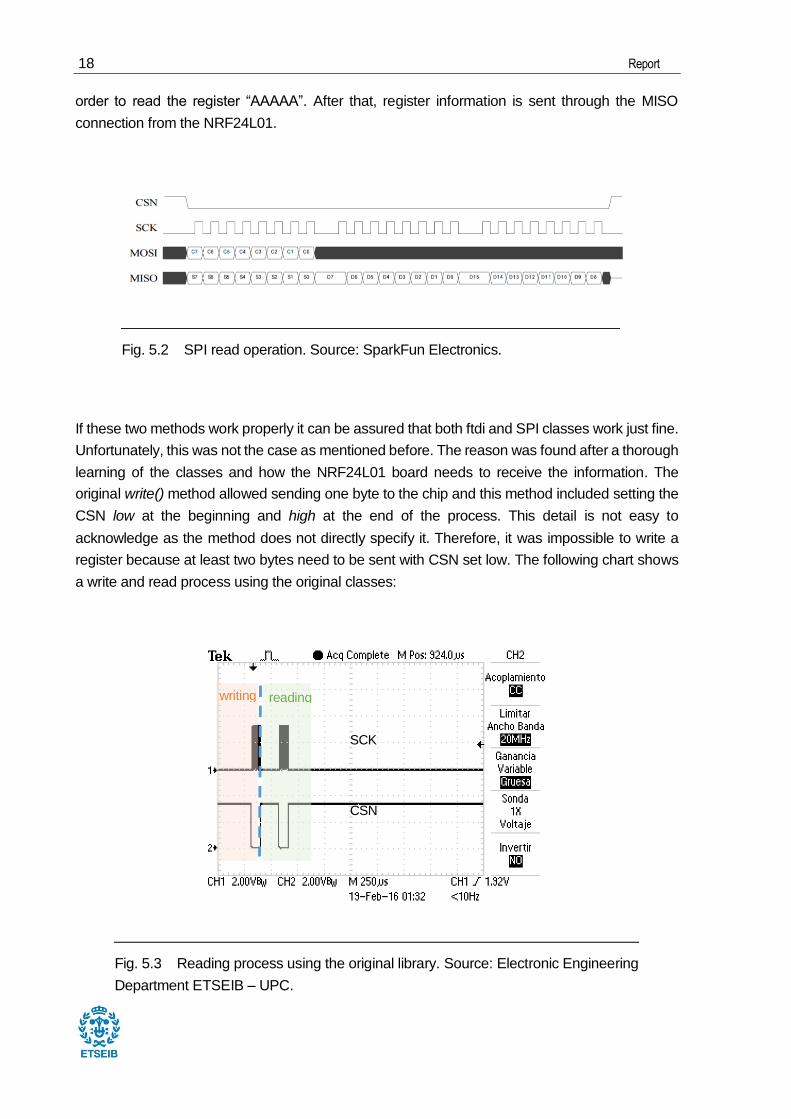
read() method
It is basically the same process although the command that needs to be sent is “000AAAAA” in
Fig. 5.1 SPI write operation. Source: SparkFun Electronics.
18 Report
order to read the register “AAAAA”. After that, register information is sent through the MISO
connection from the NRF24L01.
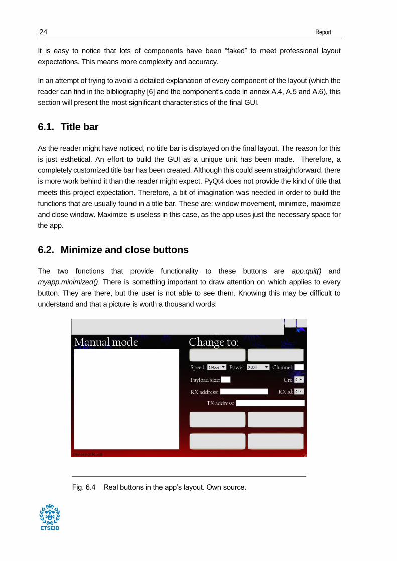
If these two methods work properly it can be assured that both ftdi and SPI classes work just fine.
Unfortunately, this was not the case as mentioned before. The reason was found after a thorough
learning of the classes and how the NRF24L01 board needs to receive the information. The
original write() method allowed sending one byte to the chip and this method included setting the
CSN low at the beginning and high at the end of the process. This detail is not easy to
acknowledge as the method does not directly specify it. Therefore, it was impossible to write a
register because at least two bytes need to be sent with CSN set low. The following chart shows
a write and read process using the original classes:
Fig. 5.3 Reading process using the original library. Source: Electronic Engineering
Department ETSEIB – UPC.
Fig. 5.2 SPI read operation. Source: SparkFun Electronics.
SCK
CSN
reading writing

Development of a Python application for monitoring RF messages using one NRF24L01 board and a USB-MPSSE cable 19
Fig. 5.3 shows the SCK output of the FTDI cable, which is the SPI Clock signal, and the SPI Chip
Select signal CSN. The reason for choosing the SCK to show the two processes is simply
because this signal shows when communication is taking place so that both writing and reading
processes can be seen. Every peak level represents a byte sent or received regarding the write
and read methods explained before. It is easy to see that the CSN signal is not working properly.
Here is how it performs once the original library has been modified:
Once the problem was identified, the next step was to decide how to modify these methods in
order to optimize their utility. Since the number of bytes written and read could vary depending on
what was read or written (not only one byte registers), the decision of removing CSN actions was
taken. Thus, the function of these methods has been limited to reading and writing one byte. This
allows great flexibility when building upper level classes. Moreover, the classes have been
modified in terms of removing useless methods and duplicities, in order to adapt the code to meet
this project needs. A full description of the methods regarding these classes can be found here.
Annex A.1 provides the python file containing both classes.
5.2. Second level class NRF24L01
Although first_level_class.py provides basic communication with the chip, a more complex
communication process is needed as the main objective is to be able to receive and send data
from and to another device. A micropython NRF24L01 class [4] has been used for this purpose.
Since this project does not operate with micropython it is necessary to adapt the code in that
sense. In addition, it is especially important to fully understand the methods of the NRF24L01
class in order to link successfully this class with the first level classes. A full description of the file
Fig. 5.4 Reading process with the modified library. Source: Electronic
Engineering Department ETSEIB – UPC.
u

20 Report
that contains this class is available here. The full code is available in annex A.2. These are the
main characteristics regarding this class.
Resetting and initializing
SPI class must be initialized so that all of its methods are available and ready to use. After
initialization, every relevant register is set to a default value.
Low(pin) and high(pin) methods
Set CSN or CE (Chip Enable) into a low or high level. These methods, coupled with the read and
write from the SPI class, give free rein to the other methods to perform any communication
process with total flexibility.
Reg_read() and reg_write() methods
These functions were specially built to read and write registers because of its use all over the
code. With these methods the NRF24L01 device can be freely configured. The class contains a
bunch of methods which permit a direct and intuitive configuration of the most important registers
such as flush_rx(), flush_tx(), set_power_speed(), setcrc(),...
Listening methods
This class also contains methods that will be used in a listening process such as:
open_rx_pipe: enables the pipe and the autoacknowledgement feature for that pipe
(which will be explained later) after writing the address in the correct pipe. In case the
pipe number is 2 or more, the last 4 bytes will be stored in pipe 1 address register and
the first one (in case the address is 5 bytes long) is stored in the respective pipe. Note
that all the pipes must have the same length.
Fig. 5.5 addressing data pipes. Source: SparkFun Electronics.

Development of a Python application for monitoring RF messages using one NRF24L01 board and a USB-MPSSE cable 21
start_listening(): it sets the chip in a RX mode, which means that the device is listening
from this point on. Besides, the FIFOs are cleaned to ensure that new data can be stored.
stop_listening(): sets the chip back to a standby mode which prevents the NRF24L01
from capturing more packets.
start_sending(msg): sends a packet containing the message “msg” according to the
configuration that has been applied to the chip.

22 Report
6. GUI
Before reaching the top of the pyramid, it makes sense to explain how the Graphic User Interface
has been built as in the next section everything will be put together.
PyQt4 [4,5], a python module from Riverbank computing (www.riverbankcomputing.com), has
been used for this purpose. According to Riverbank computing [5], PyQt is a set of Python v2 and
v3 bindings for The Qt Company's Qt application framework and runs on all platforms supported
by Qt including Windows, MacOS/X and Linux. The bindings are implemented as a set of Python
modules and contain over 1,000 classes. Although it provides a handful of components, only
QtGui and QtCore will be used for this project.
Besides, the GUI has been developed using Qt Designer, which is a Qt’s tool that helps building
a GUI. It basically consists on dragging and dropping elements onto a window until you got
everything you need. Then, it just needs to be saved and converted to a py file format. It is worth
mentioning that although this is a useful tool, the result is a really basic GUI, which makes almost
inevitable the manual modifications of the given class.
The developed application is formed by three GUI classes according to each mode available in
the app. Every class is contained in a different file, so that the reader can quickly distinguish
between interfaces. These files are manual_mode.py, automatic_mode.py and
multireceiving_mode.py. It is important to draw attention to the fact that the classes that are going
Fig. 6.1 Qt Designer interface. Shaping the GUI. Own Source.

Development of a Python application for monitoring RF messages using one NRF24L01 board and a USB-MPSSE cable 23
to be explained here are the final result from a series of intermediate steps which goes from the
most basic GUI developed with Qt Designer to a more complex layout (manually modified). Here
is a before/after layout:
Fig 6.2 First basic layout made with Qt Designer. Own source.
Fig 6.3 Final layout (manually modified). Own source.
24 Report
It is easy to notice that lots of components have been “faked” to meet professional layout
expectations. This means more complexity and accuracy.
In an attempt of trying to avoid a detailed explanation of every component of the layout (which the
reader can find in the bibliography [6] and the component’s code in annex A.4, A.5 and A.6), this
section will present the most significant characteristics of the final GUI.
6.1. Title bar
As the reader might have noticed, no title bar is displayed on the final layout. The reason for this
is just esthetical. An effort to build the GUI as a unique unit has been made. Therefore, a
completely customized title bar has been created. Although this could seem straightforward, there
is more work behind it than the reader might expect. PyQt4 does not provide the kind of title that
meets this project expectation. Therefore, a bit of imagination was needed in order to build the
functions that are usually found in a title bar. These are: window movement, minimize, maximize
and close window. Maximize is useless in this case, as the app uses just the necessary space for
the app.
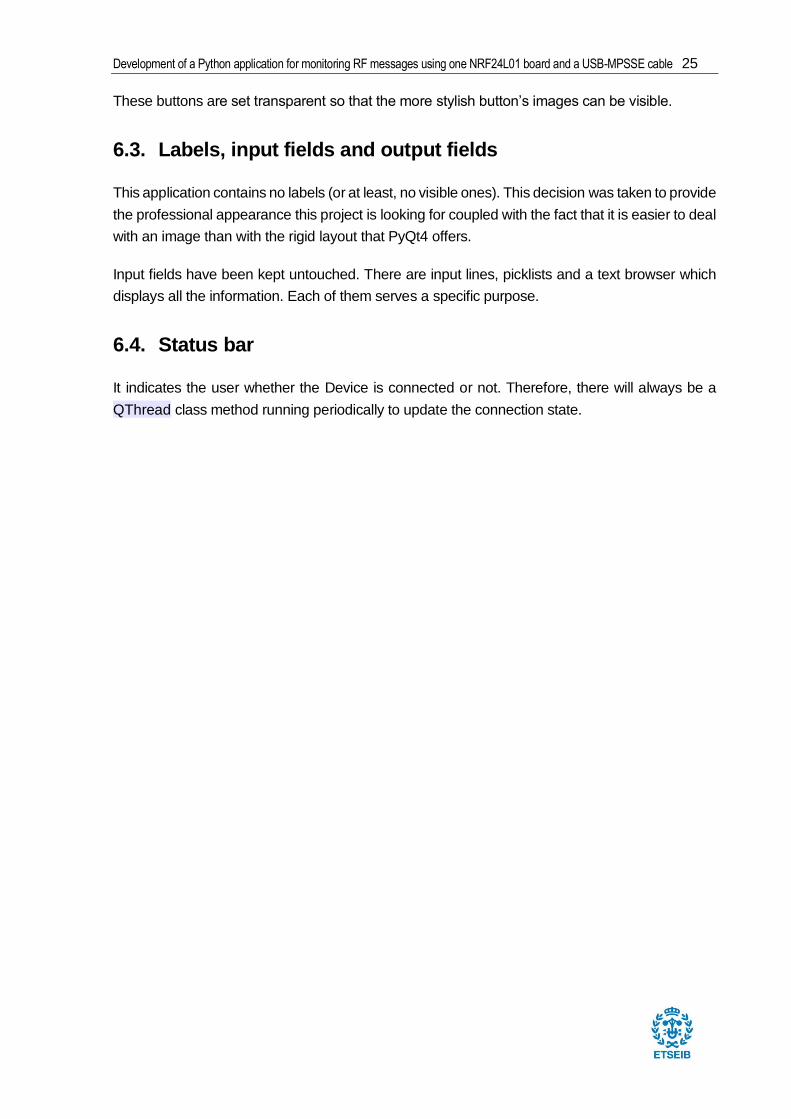
6.2. Minimize and close buttons
The two functions that provide functionality to these buttons are app.quit() and
myapp.minimized(). There is something important to draw attention on which applies to every
button. They are there, but the user is not able to see them. Knowing this may be difficult to
understand and that a picture is worth a thousand words:
Fig. 6.4 Real buttons in the app’s layout. Own source.
Development of a Python application for monitoring RF messages using one NRF24L01 board and a USB-MPSSE cable 25
These buttons are set transparent so that the more stylish button’s images can be visible.
6.3. Labels, input fields and output fields
This application contains no labels (or at least, no visible ones). This decision was taken to provide
the professional appearance this project is looking for coupled with the fact that it is easier to deal
with an image than with the rigid layout that PyQt4 offers.
Input fields have been kept untouched. There are input lines, picklists and a text browser which
displays all the information. Each of them serves a specific purpose.
6.4. Status bar
It indicates the user whether the Device is connected or not. Therefore, there will always be a
QThread class method running periodically to update the connection state.

26 Report
7. app.py file
Once all the necessary tools to build this application have been exposed, it is time to put
everything together and make it work. Since the app will display three configuration modes, it has
been considered sensible to maintain the same structure in the code as well. Therefore, in the
app.py file, three main classes (ManualMode, AutomaticMode and MultireceivingMode) can be
found corresponding to each mode. The other classes support these latter ones. This file acts as
a controller which manages the input parameters and actions that the user displays through the
GUI and translate these inputs into actions that the NRF24L01 class can understand and vice
versa. Detailed documentation about this file can be found here. The full code is available in annex
A.3. This is how this section will be structure:
GeneralModeFunctions class
QThread classes
Manual mode
Multireceiving mode
Automatic mode
Tests
7.1. GeneralModeFunctions class
Since most of the methods and attributes are similar in every mode class (if not equal), the
decision of joining all these methods and attributes together in one single class was taken. This
class was named GeneralModeFunctions.
7.1.1. Inheritance
Because these mode classes inherit from QtGui.QMainWindow, GeneralModeFunctions
needs to inherit this class to actually be able to execute the methods and attributes from the mode
classes without problems. This is the inheritance structure:
QtGui.QMainWindow()
GeneralModeFunctions()
ManualMode() AutomaticMode() MultireceivingMode
Fig 7.1 Mode classes’ Inheritance structure. Own source.

Development of a Python application for monitoring RF messages using one NRF24L01 board and a USB-MPSSE cable 27
7.1.2. Methods
These methods are available to every mode class.
7.1.2.1. listening()
It is triggered when clicking the “Listen” button. This function is a very important one not only
because it sets the NRF24L01 in a listening state but also because in order to do that, it has to
call another class named ListeningLoop which is a thread. The reason of being of this thread is
the need of a loop when listening. If the loop was written in this method, the app would get stuck
and would not respond. Therefore, the loop must be executed in another class that runs
simultaneously together with one of the mode classes. If the method fails execution, a message
will let the user know whether it is due to a loss of connection or because the parameters have
not been applied yet. If it is owing to a loss of connection by popping up a message box informing
the user about the problem.
7.1.2.2. stop_listening()
It runs when the “Stop” button is clicked. It makes the NRF24L01 stop listening, which means
returning to a standby state (which also consumes less energy). A message confirming the
execution of this method is shown on the text browser. If the method fails, it will proceed as in the
listening() method.
7.1.2.3. end_Get_CheckConnection()
It is executed when a signal is received from GetConnection or CheckConnection class.
That is, when connection is established or lost. It just updates the status bar, terminates the thread
from which the signal comes from and starts the other one. Note that there is always one thread
running, GetConnection or CheckConnection.
7.1.2.4. add_to_record(s)
Normally, displays information to the user via the text browser. It also saves the displayed
information in a text file named as the mode that is currently running. This information is
overwritten every time the app is executed. This avoids deluging the folder with hundreds of files.
Nevertheless, if Focus or Fast file download modes are enabled it plays a whole different role

28 Report
which is explained in detail on the sphinx documentation available here.
7.1.2.5. Change_mode()
This method is executed when the user presses the “Manual mode”, “Automatic mode” or
“Multireceiving mode” button. It closes the current GUI and opens a new one according to the
mode that the user chose. It also terminates the threads if they were running and passes the new
window's position.
7.2. QThread classes
All the classes that are presented in this section inherit from QtCore.QThread and are isolated
from the main classes for one of two reasons. A huge number of calculations take place in their
run() method which prevents the app from running correctly, which is the case of
packet_validation(), or because these classes’ run() method contain a loop that needs to be
executed simultaneously together with the current mode class. Note that all these classes
automatically execute its run method (where all the code is located) when the class is started.
These classes are:
7.2.1. Intro class
This class is only initialized and started by ManualMode class. It is only executed the first time
that ManualMode is called. It provides a 3 seconds Introduction image to the app and its owner
which is the following.

Development of a Python application for monitoring RF messages using one NRF24L01 board and a USB-MPSSE cable 29
7.2.2. Move class
Since this app has an especial title bar and the function of dragging the window is executed when
pressing long invisible button at the top of the window, this functionality is carried out by this class.
Whenever the button is “pressed” (not clicked), the run() method from this class is executed. This
method consists of a loop which maintains the relative distance (and angle, of course) between
the mouse and the window while the button is pressed. Nevertheless, it is possible that the loop
does not update fast enough the relative distance which causes the mouse being outside the
button which stopped the loop because the mouse was no longer pressing the button but another
part of the screen. This problem was tackled by focusing on the on the mouse state (left click
pressed or not pressed) instead of focusing on the button once the button was pressed.
7.2.3. GetConnection class
This class is triggered every time the device is disconnected. Therefore, it will run at least one
time, right at the beginning. It basically consists of a loop that is constantly trying to stablish
communication with the device. If it can, the state of the status bar will change to “Connected” in
green and a message confirming this connection is displayed in the text browser.
Fig. 7.2 Introduction image to the app. Own source.

30 Report
7.2.3.1. Checkconnection class
Whenever the GetConnection loop stops running, the Checkconnection loop does. In this
case, this loop does not check the device connection, as this would mean sending information
through the FTDI cable and expecting something in return. This is not good practice since the app
could be applying parameters or be in the listening loop while this happens which would turn out
badly due to the fact that both signals would be sent through the cable simultaneously.
Notwithstanding this, it is possible to check the cable’s connection without interfering with the
device and this is what this class actually does.
7.2.4. ListeningLoop class
It runs a loop in which it checks if the any() method from the NRF24L01 class returns True and, if
so, sends a signal to the current mode class when something is received. If the device is
disconnected while running this loop, a signal is sent to the current mode class which triggers a
method that pops up a message on the screen informing of this unexpected disconnection.
Fig. 7.3 Status bar states. Own source.
Fig. 7.4 Error message box due to an unexpected device disconnection. Own source.
Development of a Python application for monitoring RF messages using one NRF24L01 board and a USB-MPSSE cable 31
7.2.5. PacketValidation class
This class is of paramount importance not only for its complexity but also because it to catch a
packet without knowing almost anything about it. The process regarding this class will be tackled
in section 7.5.4.
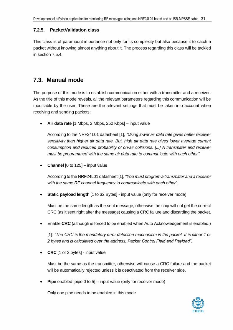
7.3. Manual mode
The purpose of this mode is to establish communication either with a transmitter and a receiver.
As the title of this mode reveals, all the relevant parameters regarding this communication will be
modifiable by the user. These are the relevant settings that must be taken into account when
receiving and sending packets:
Air data rate [1 Mbps, 2 Mbps, 250 Kbps] – input value
According to the NRF24L01 datasheet [1], “Using lower air data rate gives better receiver
sensitivity than higher air data rate. But, high air data rate gives lower average current
consumption and reduced probability of on-air collisions. [...] A transmitter and receiver
must be programmed with the same air data rate to communicate with each other”.
Channel [0 to 125] – input value
According to the NRF24L01 datasheet [1], “You must program a transmitter and a receiver
with the same RF channel frequency to communicate with each other”.
Static payload length [1 to 32 Bytes] - input value (only for receiver mode)
Must be the same length as the sent message, otherwise the chip will not get the correct
CRC (as it sent right after the message) causing a CRC failure and discarding the packet.
Enable CRC (although is forced to be enabled when Auto Acknowledgement is enabled.)
[1]: “The CRC is the mandatory error detection mechanism in the packet. It is either 1 or
2 bytes and is calculated over the address, Packet Control Field and Payload”.
CRC [1 or 2 bytes] - input value
Must be the same as the transmitter, otherwise will cause a CRC failure and the packet
will be automatically rejected unless it is deactivated from the receiver side.
Pipe enabled [pipe 0 to 5] – input value (only for receiver mode)
Only one pipe needs to be enabled in this mode.

32 Report
Enhanced ShockBurst enabled for the chosen pipe
Normally, messages are sent with Enhanced ShockBurst enabled.
Pipe address – input value
Must be the same as the transmitter address and set in the pipe address that has been
enabled
PWR_UP, PRIM_RX registers and CE must be set high to enter in RX mode
PWR_UP - if set high, the NRF24L01 enters standby-I mode.
CE - if set high, the NRF24L01 enters standby-II mode.
RIM_RX - if set high, the device enters in RX mode.
Dynamic Payload – This feature permits automatic payload detection for the receiver
only if Dynamic Payload has been enabled from the transmitter, otherwise the payload length will not be set in the transmitted packet
The following table shows how both the receiver and the transmitter should be configured to be
able to communicate with each other:
Input Settings
Air rate Same for the receiver and the transmitter
Channel Same for the receiver and the transmitter
CRC Same for the receiver and the transmitter
Pipe Not relevant
Pipe address Same for the receiver and the transmitter
Registers’ configuration
Register Receiver Transmitter
00
0b1001 (1 byte CRC)
0b1101 (2 bytes CRC)
0b1000 (1 byte CRC)
0b1100 (2 bytes CRC)
01
0b111111 – Enhanced
ShockBurst enabled in all
pipes
Not relevant

Development of a Python application for monitoring RF messages using one NRF24L01 board and a USB-MPSSE cable 33
02 0b111111 – Enable all pipes Not relevant
03 Address width for all pipes Address width (related to
register 10)
04 Not relevant Not relevant
05 Same for the receiver and the
transmitter
Same for the receiver and
the transmitter
06 Same for the receiver and the
transmitter
Same for the receiver and
the transmitter
07 Not relevant Not relevant
08 Not relevant Not relevant
09 Default Default
0A
One of these registers must fit
the TX address sent by the
transmitter (notice LSB is
written first)
Not relevant
0B The register that corresponds
to the chosen pipe to receive
the information must have the
same length as the TX
address from the transmitter
Not relevant
0C Not relevant
0D Not relevant
0E Not relevant
0F Not relevant
10
Not relevant The introduced address
must equal the chosen RX
pipe address (notice LSB is
written first)
11
Choose the desired payload
width for the chosen pipe
Not relevant
12 Not relevant
13 Not relevant

34 Report
14 Not relevant
15 Not relevant
16 Not relevant
17 Default Not relevant
1C Not relevant Not relevant
1D Not relevant Not relevant
If all these registers were overwritten in both the transmitter and the receiver and CE signal was
set high in both chips (first on the receiver and then the transmitter so that the message can be
received before being sent and not after), the message should be saved in the RX FIFO from the
receiver which can be easily accessed with the R_RX_PAYLOAD command as will be shown in
the following section.
7.3.1. ManualMode class
The mode classes contain the specific attributes and methods regarding the mode (annex A.3).
7.3.1.1. The constructor
As this class inherits from GeneralModeFunctions, two parameters must be passed to the
inherited class which are: an instance of the GUI class from the corresponding mode and the
name of the text file that is going to be used as a record.
This class needs no other attribute to run properly (apart from the ones inherited). However, there
is a short presentation which turns up every time the program is executed where the logo of the
app appears together with the owner’s name.
It is actually very basic. There is a global variable which is True by default so that the first time the
if statement is executed, it initializes an Intro() instance and then starts the QThread class. This
QThread class (Intro()) runs automatically its method run(), which makes the program wait for
3 seconds before hiding the intro and letting the user see the Manual mode interface.
Table 7.1 Registers’ configuration. Own source.

Development of a Python application for monitoring RF messages using one NRF24L01 board and a USB-MPSSE cable 35
7.3.1.2. apply_new_parameters() method
It tries to apply the input parameters chosen by the user into the NRF24L01. If it fails a message
box will tell the user whether is it due to an unacceptable input or because the app lost connection
with the chip (if this is the case, GetConnection class will be started, which will wait for the device
to be connected). If it succeeds, parameters will appear on the text browser together with a
message confirming the success. It also checks if the user has clicked on stop_listening() after
clicking on listening. If not, stop_listening() method is executed before applying the parameters.
7.3.1.3. read() method
It gets the message by calling the recv() method from the NRF24L01 class and prints it on the
text browser
7.3.1.4. tx_message() method
Opens an input window were the user can write the message that wants to send. The message
must be written as in the Address input field. When the user clicks the “OK” button this method
calls the sending() method.
7.3.1.5. sending() method
This method actually sends the packet by calling start_sending() from the NRF24L01 class. After
that, it checks whether the message was correctly sent. Then it waits for the acknowledgement
packet in case that option was checked by the user. When the acknowledgement packet has
been received, a message informs the user about that fact.
7.3.2. Example
In this example, both the transmitter and the receiver can be configured with this application as
will be shown.
The transmitter and the receiver will have the following characteristics:
Address: 0xB2B3B4
Message (transmitter): 0x01
Air rate: 1Mbps
Power (transmitter): 0 dBm
CRC: 1 byte
Pipe number used (receiver): 0

36 Report
Using the app, the chip configuration is as follows:
Register Map configuration
Register Receiver Transmitter
00 0x09 0x08
01 0x01 0x3F
02 0x01 0x3F
03 0x01 0x02
04 0x68 0x0A
05 0x40 0x40
06 0x7 0x07
07 0x0E 0x0E
08 0x00 0x1A
09 0x00 0x00
0A 0xB4 0xB3 0xB2 0x01 0x04 0xB3
0B 0x00 0xC2
0C 0x00 0xC3
0D 0x00 0xC4
0E 0x00 0xC5
0F 0x00 0xC6
10 0x00 0xB4 0xB3 0xB2
11 0x01 0x05
12 0x00 0x00
13 0x00 0x00
14 0x00 0x00
Development of a Python application for monitoring RF messages using one NRF24L01 board and a USB-MPSSE cable 37
15 0x00 0x00
16 0x00 0x00
17 0x11 0x01
1C 0x3F 0x3F
1D 0x3F 0x3F
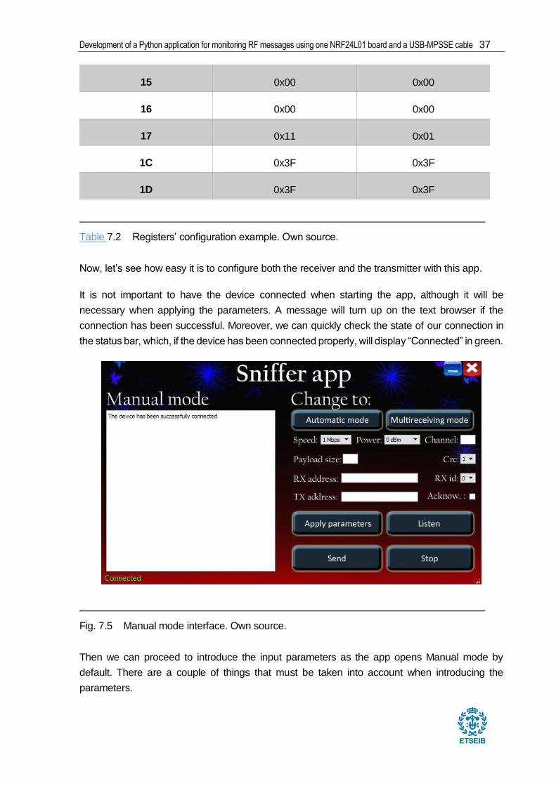
Now, let’s see how easy it is to configure both the receiver and the transmitter with this app.
It is not important to have the device connected when starting the app, although it will be
necessary when applying the parameters. A message will turn up on the text browser if the
connection has been successful. Moreover, we can quickly check the state of our connection in
the status bar, which, if the device has been connected properly, will display “Connected” in green.
Then we can proceed to introduce the input parameters as the app opens Manual mode by
default. There are a couple of things that must be taken into account when introducing the
parameters.
Table 7.2 Registers’ configuration example. Own source.
Fig. 7.5 Manual mode interface. Own source.

38 Report
All numbers must be written as in hexadecimal format separating every byte with a space.
For example: b1 b3 c5 01
The address can be of 3, 4 or 5 bytes long
The address is written in reverse to the register it is written from the Least Significant Byte
(LSB) to the Most Significant Byte (MSB). That is because it is easier to understand the
address writing first the MSB (this will be of paramount importance in the Automatic
mode).
Receiver:
The transmitters code for this example is available in annex C. This configuration can be easily
set throughout the app by fulfilling the parameters and clicking on “Apply parameters”.
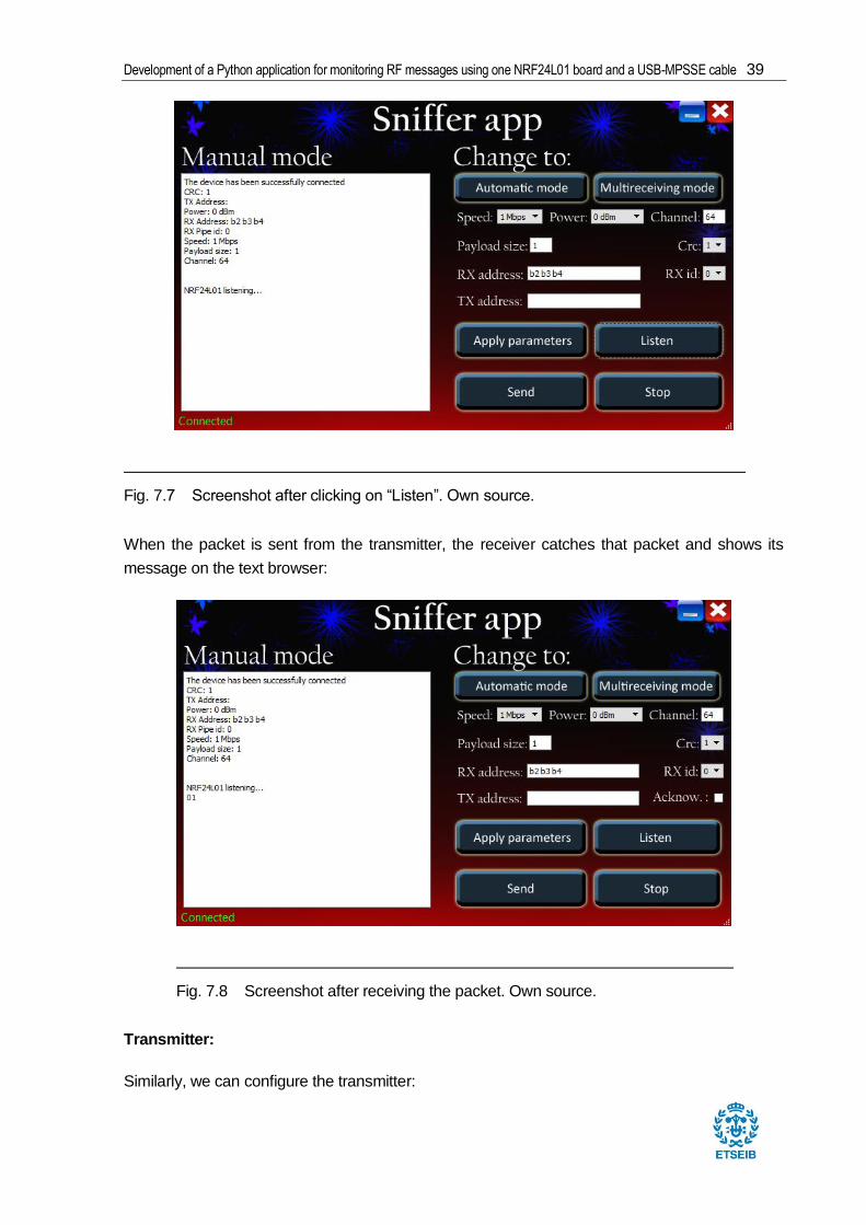
Now we just need to click on “Listen” to start receiving packets:
Fig. 7.6 Screenshot after clicking on “Apply parameters”. Own source.
Development of a Python application for monitoring RF messages using one NRF24L01 board and a USB-MPSSE cable 39
When the packet is sent from the transmitter, the receiver catches that packet and shows its
message on the text browser:
Transmitter:
Similarly, we can configure the transmitter:
Fig. 7.7 Screenshot after clicking on “Listen”. Own source.
Fig. 7.8 Screenshot after receiving the packet. Own source.
40 Report
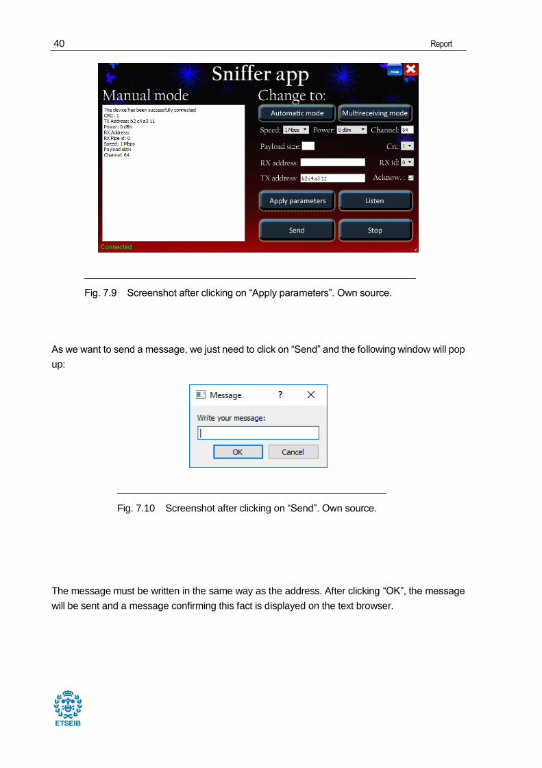
As we want to send a message, we just need to click on “Send” and the following window will pop
up:
The message must be written in the same way as the address. After clicking “OK”, the message
will be sent and a message confirming this fact is displayed on the text browser.
Fig. 7.9 Screenshot after clicking on “Apply parameters”. Own source.
Fig. 7.10 Screenshot after clicking on “Send”. Own source.

Development of a Python application for monitoring RF messages using one NRF24L01 board and a USB-MPSSE cable 41
7.4. Multireceiving mode
Once all the problems from the Manual mode have been overcome, this mode turns out really
simple (annex A.3). The strong point of it is the capacity of receiving messages from different
addresses, this is, the possibility to communicate among different devices at the same time. This
can be achieved thanks to the 6 receiving pipes integrated in the NRF24L01.
7.4.1. Multireceiving_mode class
The methods that make this class work are the followings.
7.4.1.1. apply_new_parameters()
This method configures the NRF24L01 to be ready for listening. Notice that this method leaves
the chip in a low energy consumption state. This means, it is not “listening” yet. Here is the
configuration table where the reader can see which fields are required and how they must be
fulfilled.
Fig. 7.11 Screenshot after clicking on “OK”. Own source.

42 Report
Input Settings
Air rate Same for the receiver and the transmitter
Channel Same for the receiver and the transmitter
CRC Same for the receiver and the transmitter
Pipe Not relevant
Pipe address Same first three bytes for the receiver and the transmitter
Register Map configuration
Register Receiver Transmitter
00 0b1000 (1 byte CRC)
0b1100 (2 bytes CRC)
0x0C
01 0b111111 – Enhanced
ShockBurst enabled in all
pipes
Not relevant
02 0b111111 – Enable all pipes Not relevant
03 Address width for all pipes Address width (related to
register 10)
04 Not relevant Not relevant
05 Same for the receiver and the
transmitter
Same for the receiver and
the transmitter
06 Same for the receiver and the
transmitter
Same for the receiver and
the transmitter
07 Not relevant Not relevant
08 Not relevant Not relevant
09 Default Default
0A One of these registers must fit Not relevant

Development of a Python application for monitoring RF messages using one NRF24L01 board and a USB-MPSSE cable 43
0B the TX address sent by the
transmitter (notice LSB is
written first)
Not relevant
0C Not relevant
0D Not relevant
0E Not relevant
0F Not relevant
10 Not relevant The introduced address
must equal one enabled
RX pipe address (notice
LSB is written first)
11 The pipe that is going to be
used must have a 32 bytes
payload width
Not relevant
12 Not relevant Not relevant
13 Not relevant Not relevant
14 Not relevant Not relevant
15 Not relevant Not relevant
16 Not relevant Not relevant
17 Default Default
1C Not relevant Not relevant
1D Not relevant Dynamic Payload Length
Enabled
7.4.1.2. read()
This method is similar to the read() from Manual mode. Nevertheless, it also prints the pipe from
where the message has been caught on the screen so that the user can easily tell which
Table 7.3 Registers’ configuration. Own source.

44 Report
transmitter is sending the information by checking the address of the pipe.
7.4.2. Example
Transmitter’s code for this example is available in annex D. To perform this example and actually
use the functionality that this mode provides, several transmitters are needed. For this example,
3 transmitters were used:
These transmitters have been configured as follows (annex D):
Transmitters’ packet characteristics
Addresses 0xB1 0xB2 0xB3 0xB4 0x01/02/03
Channel 64 (2464 [MHz])
Air rate 1Mbps
Power 0 dBm
Fig. 7.12 Receiver (left hand) connected to the laptop and 3 transmitters connected to
Open18F4520 boards. Own source.

Development of a Python application for monitoring RF messages using one NRF24L01 board and a USB-MPSSE cable 45
CRC 2 Bytes
Dynamic Payload Enabled
Message 1 2 4 8 15
In order to receive all the packets sent by the transmitter, the following parameters must be set
within the app to configure the receiver accordingly.
After applying the parameters, the user just needs to click on “Listen” to be ready to receive
packets. The following image shows the messages that have been received coupled with the pipe
that contains the address from which the messages have been sent. This means that the user
can easily recognise the transmitter that sent the message.
Table 7.4 Transmitters’ packet characteristics. Own source.
Fig. 7.13 Example parameters. Transmitters’ addresses are set in pipes 0, 2 and 4. Own
source.

46 Report
Fig. 7.14 Screenshot of the messages that have been received from different pipes. Own
source.

Development of a Python application for monitoring RF messages using one NRF24L01 board and a USB-MPSSE cable 47
7.5. Automatic mode
This is probably the most complex mode in this application. Its aim is to get the message from a
3, 4 or 5 bytes address packet, knowing only the first 4 or even 3 bytes and nothing else (it also
works with 5). This “nothing else” has important consequences. It allows the receiver to extract
the message sent by different transmitters regardless of their configurations (address length,
payload length and the CRC length). It basically reads every message contained in a packet that
starts with the first 3 chosen bytes. The implications are impressive, however, this adds a lot of
complexity to the message extraction, problems that will need to be tackled.
This mode is an enhanced variant of the so called Promiscuous Reading [10], which is the ability
to receive a packet by knowing just a part of its address. It allows the receiver to get messages
from up to 65793 different transmitters in contrast with the 6 different pipes that the device
provides thanks to the Multireceiver functionality. Unfortunately, this Promiscuous Reading is not
available in the NRF24L01, therefore, it will be applied manually using software.
This is achieved by configuring the receiver to receive a 3 or 4 bytes address with Enhanced
Shockburst disabled. By doing so, the device will not check anything that comes after the address
(mainly the CRC) and will just pass as much data to RX FIFO (first in, first out) as it can store (32
bytes).
Up to this point, the device is able to capture the packet, which contains the message.
Nevertheless, this packet is hidden among many other bits. This means that the chip will not know
either where the message exactly begins or where it ends. This makes it almost impossible to
extract the correct message, even knowing it is among this large row of ones and zeros that the
device has captured. Here are a few samples to exemplify this point:
1
The answer to this problem lies in the Enhanced ShockBurst packet structure. Messages are
1 PCF (Packet Control Field) include the payload length, the PID and the no acknowledgement bit.
Fig. 7.15 This figure shows that it is not possible (a priori) to know for sure where the
message begins and where it ends. Own source.
48 Report
usually wrapped up in an Enhanced ShockBurst packet format. This packet contains (apart from
the message) metadata such as the length of the message, the PID (Packet Identity), the No
Acknowledgement bit and a CRC validation. These parts of the packet will not only help in the
message extraction, but also provide important information about the transmitters configuration
such as the CRC length and the full address which will be very useful in future sections.
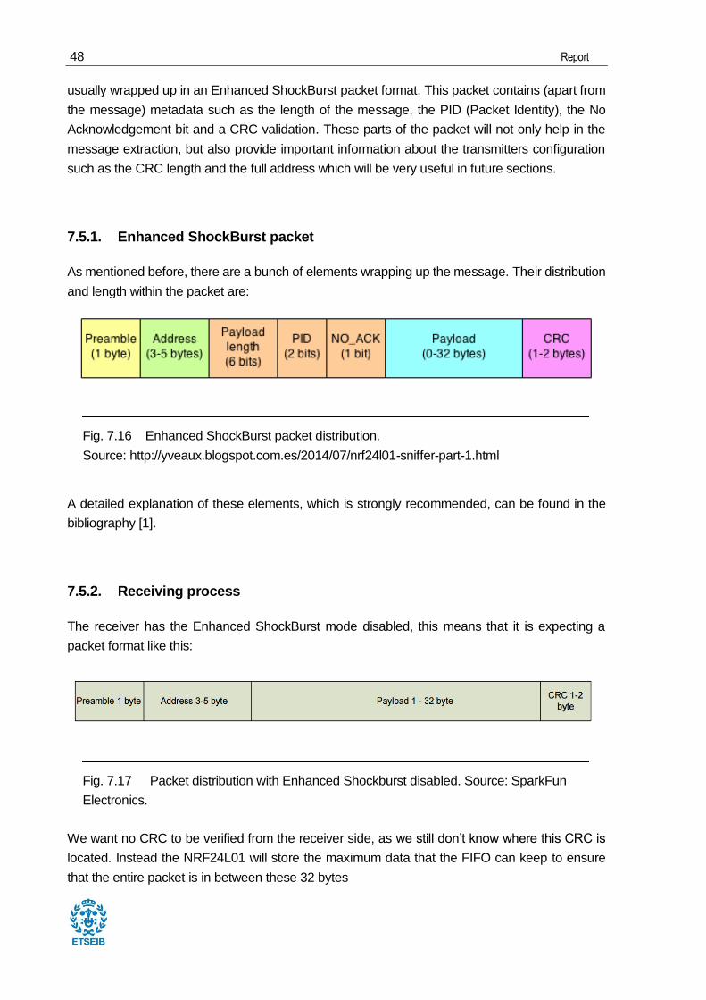
7.5.1. Enhanced ShockBurst packet
As mentioned before, there are a bunch of elements wrapping up the message. Their distribution
and length within the packet are:
A detailed explanation of these elements, which is strongly recommended, can be found in the
bibliography [1].
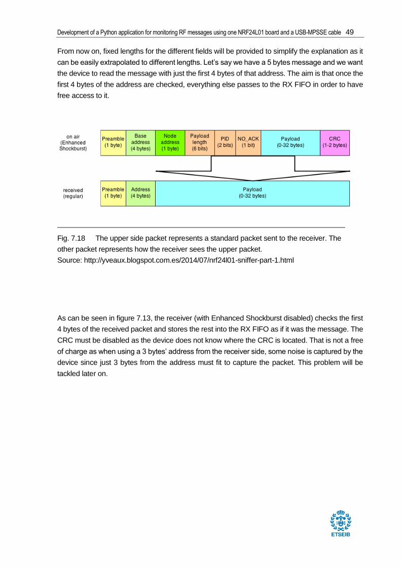
7.5.2. Receiving process
The receiver has the Enhanced ShockBurst mode disabled, this means that it is expecting a
packet format like this:
We want no CRC to be verified from the receiver side, as we still don’t know where this CRC is
located. Instead the NRF24L01 will store the maximum data that the FIFO can keep to ensure
that the entire packet is in between these 32 bytes
Fig. 7.16 Enhanced ShockBurst packet distribution.
Source: http://yveaux.blogspot.com.es/2014/07/nrf24l01-sniffer-part-1.html
Fig. 7.17 Packet distribution with Enhanced Shockburst disabled. Source: SparkFun
Electronics.
Development of a Python application for monitoring RF messages using one NRF24L01 board and a USB-MPSSE cable 49
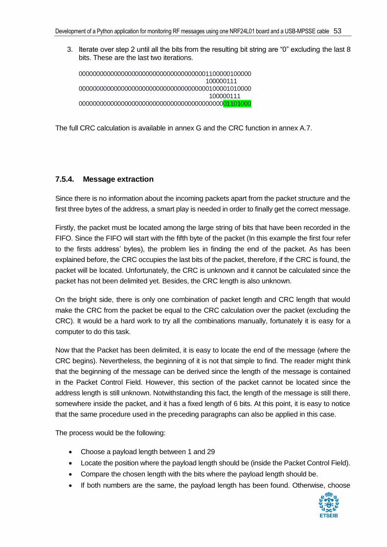
From now on, fixed lengths for the different fields will be provided to simplify the explanation as it
can be easily extrapolated to different lengths. Let’s say we have a 5 bytes message and we want
the device to read the message with just the first 4 bytes of that address. The aim is that once the
first 4 bytes of the address are checked, everything else passes to the RX FIFO in order to have
free access to it.
As can be seen in figure 7.13, the receiver (with Enhanced Shockburst disabled) checks the first
4 bytes of the received packet and stores the rest into the RX FIFO as if it was the message. The
CRC must be disabled as the device does not know where the CRC is located. That is not a free
of charge as when using a 3 bytes’ address from the receiver side, some noise is captured by the
device since just 3 bytes from the address must fit to capture the packet. This problem will be
tackled later on.
Fig. 7.18 The upper side packet represents a standard packet sent to the receiver. The
other packet represents how the receiver sees the upper packet.
Source: http://yveaux.blogspot.com.es/2014/07/nrf24l01-sniffer-part-1.html

50 Report
Now, almost all the packet (except the first 4 bytes from the address that has been checked) can
be accessed with the command R_RX_PAYLOAD.
In order to split the different sections of the packet, the information will be processed at a bit level
rather than at a byte level due to the 9 bits of the Packet Control Field. The Bitstring module will
be used for this purpose.
With all the packet information available in the RX FIFO a way needs to be found to locate every
section of the packet in order to locate the message and the full address from where the message
has been sent.
First thing to do is to delimitate the packet. Note that if the CRC is found, the packet will be
delimited since it is located right at the end of the packet. However, that is only one advantage of
finding the CRC. As we are going to see in the next section, finding the CRC will necessarily
validate the message.
7.5.3. CRC
This section explains the importance of calculating the CRC [7, 8, 9] and the process that has
Fig. 7.19 Noise detected knowing the first 3 bytes from the address. Own source.

Development of a Python application for monitoring RF messages using one NRF24L01 board and a USB-MPSSE cable 51
been followed in order to manually get it. The CRC manual calculation is important for the
following reasons:
Packet validation: The CRC is calculated over the whole packet (excluding, of course,
the CRC itself) to ensure that the receiver receives the right information from the
transmitter. This is very helpful when receiving with a 3 bytes’ address as it is easy to
receive dummy data.
Guessing packets’ payload length: if payload length is unknown, it can be derived (as
will be explained) once the CRC is located. This means knowing exactly where the
message is located (because the end of the payload is the beginning of the CRC) and
being able to extract it, which is the main aim of all these calculations.
Since the payload length is normally contained in the Packet Control Field (unless it is disabled),
this mode will “guess” the packets’ address length.
The consequence of using the CRC are impressive. Just by knowing the first 3 bytes of a
message’s address, this mode is able to present the message without errors.
But before delving into how to extract the message from a completely unknown packet, the CRC
needs to be correctly calculated.
7.5.3.1. CRC manual calculation
According to the datasheet [1]:
“The CRC is the mandatory error detection mechanism in the packet. It is either 1 or 2 bytes and
is calculated over the address, Packet Control Field and Payload.
The polynomial for 1 byte CRC is X8 + X2 + X + 1. Initial value 0xFF.
The polynomial for 2 byte CRC is X16 + X12 + X5 + 1. Initial value 0xFFFF.”
As it has been said before, CRC is calculated over a bit string which is not multiple of 8 (due to
the Packet Control Field). This is unfortunate not only because it makes it compulsory to work at
a bit level (which consume more resources) but because CRC functions available on the internet
work at a byte level which compels this project to have its own CRC calculation function.
This function has the following characteristics:
Arguments:
The bit string from which the CRC will be derived.

52 Report
An integer regarding the CRC’s length.
Return:
The resulting CRC’s bit string.
The CRC’s calculation procedure has been deeply analysed and can be found in the bibliography.
Although some modifications can be added to this procedure, it basically consists on performing
an XOR operation between the message and the polynomial in every iteration until you get the
desired CRC length. The polynomial degree must equal the desired CRC bit length. In this case,
an initial step is added to this process, which is performing an XOR operation between the
message and an initial bit string which is going to be 0xFF for the one-byte CRC and 0xFFFF for
the two-bytes CRC. The following example will provide a better understanding of how the function
works.
This is a real packet sent by a transmitter:
1011001010110011101101000000011100000000101101000
3-bytes address Packet Control Field Message CRC
Since the CRC is one-byte length, the polynomial X8 + X2 + X + 1 (100000111 converted to bit
code) will be used coupled with an initial value of 0xFF (11111111 converted to bit code) as it has
been mentioned before. The CRC is calculated over the whole packed (excluding the CRC itself),
therefore, the CRC is calculated over the bit string:
10110010101100111011010000000111000000001. In order to perform the calculations
correctly, eight “0” bits need to be appended to the end of this bit string which will end up being
the CRC. Taking all these into account, the next steps need to be followed in order to obtain the
CRC:
1. Align the initial value with the first bit of the given bit string and so on. Perform an XOR
operation between the bits in the same column. The rest remains the same.
1011001010110011101101000000011100000000100000000
11111111 ------------------------------------------------------------------------------------- 0100110110110011101101000000011100000000100000000
2. Align the first bit of the polynomial bit string with the first “1” of the resulting bit string and perform the same XOR operation as in step one.
0100110110110011101101000000011100000000100000000 100000111 ------------------------------------------------------------------------------------- 0000110001110011101101000000011100000000100000000
Development of a Python application for monitoring RF messages using one NRF24L01 board and a USB-MPSSE cable 53
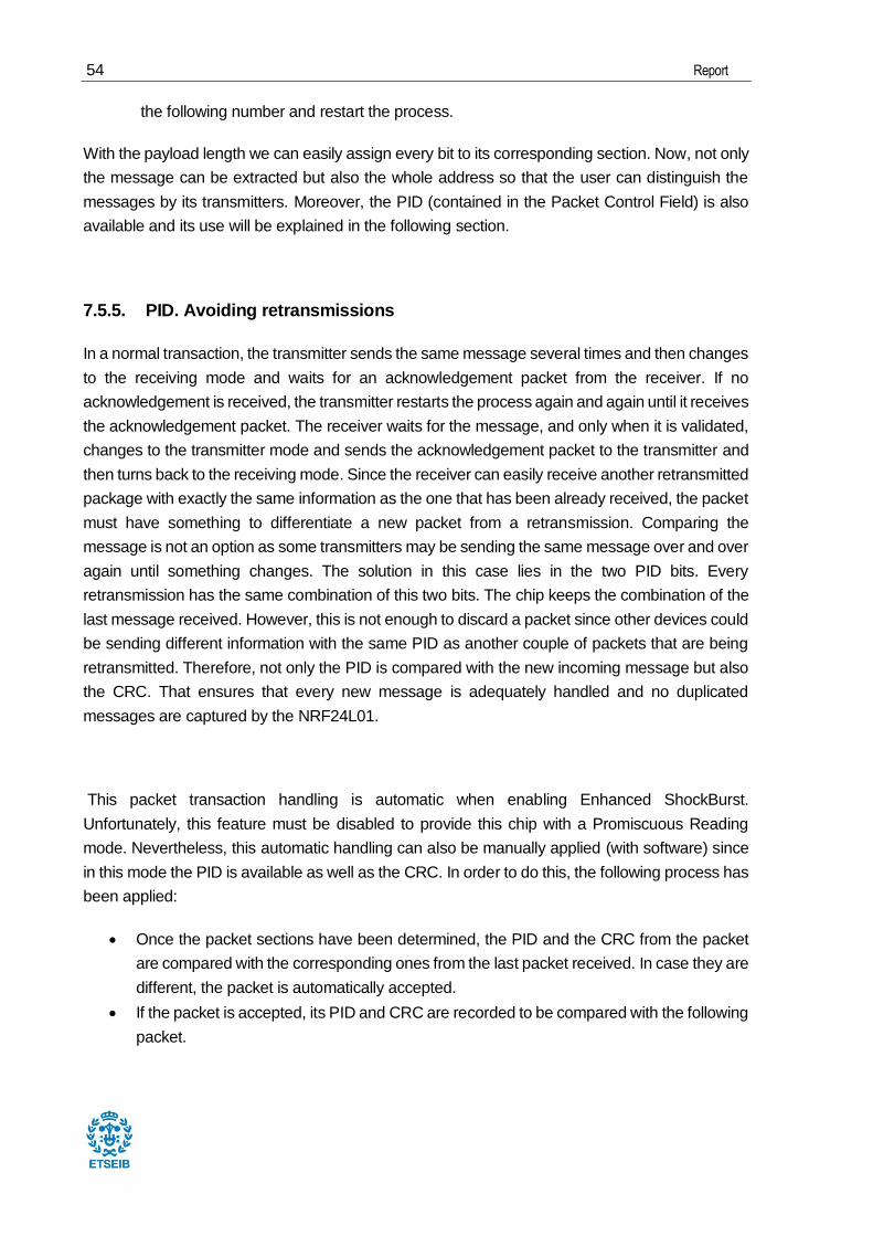
3. Iterate over step 2 until all the bits from the resulting bit string are “0” excluding the last 8 bits. These are the last two iterations. 0000000000000000000000000000000000001100000100000 100000111 0000000000000000000000000000000000000100001010000 100000111 0000000000000000000000000000000000000000001101000
The full CRC calculation is available in annex G and the CRC function in annex A.7.
7.5.4. Message extraction
Since there is no information about the incoming packets apart from the packet structure and the
first three bytes of the address, a smart play is needed in order to finally get the correct message.
Firstly, the packet must be located among the large string of bits that have been recorded in the
FIFO. Since the FIFO will start with the fifth byte of the packet (In this example the first four refer
to the firsts address’ bytes), the problem lies in finding the end of the packet. As has been
explained before, the CRC occupies the last bits of the packet, therefore, if the CRC is found, the
packet will be located. Unfortunately, the CRC is unknown and it cannot be calculated since the
packet has not been delimited yet. Besides, the CRC length is also unknown.
On the bright side, there is only one combination of packet length and CRC length that would
make the CRC from the packet be equal to the CRC calculation over the packet (excluding the
CRC). It would be a hard work to try all the combinations manually, fortunately it is easy for a
computer to do this task.
Now that the Packet has been delimited, it is easy to locate the end of the message (where the
CRC begins). Nevertheless, the beginning of it is not that simple to find. The reader might think
that the beginning of the message can be derived since the length of the message is contained
in the Packet Control Field. However, this section of the packet cannot be located since the
address length is still unknown. Notwithstanding this fact, the length of the message is still there,
somewhere inside the packet, and it has a fixed length of 6 bits. At this point, it is easy to notice
that the same procedure used in the preceding paragraphs can also be applied in this case.
The process would be the following:
Choose a payload length between 1 and 29
Locate the position where the payload length should be (inside the Packet Control Field).
Compare the chosen length with the bits where the payload length should be.
If both numbers are the same, the payload length has been found. Otherwise, choose
54 Report
the following number and restart the process.
With the payload length we can easily assign every bit to its corresponding section. Now, not only
the message can be extracted but also the whole address so that the user can distinguish the
messages by its transmitters. Moreover, the PID (contained in the Packet Control Field) is also
available and its use will be explained in the following section.
7.5.5. PID. Avoiding retransmissions
In a normal transaction, the transmitter sends the same message several times and then changes
to the receiving mode and waits for an acknowledgement packet from the receiver. If no
acknowledgement is received, the transmitter restarts the process again and again until it receives
the acknowledgement packet. The receiver waits for the message, and only when it is validated,
changes to the transmitter mode and sends the acknowledgement packet to the transmitter and
then turns back to the receiving mode. Since the receiver can easily receive another retransmitted
package with exactly the same information as the one that has been already received, the packet
must have something to differentiate a new packet from a retransmission. Comparing the
message is not an option as some transmitters may be sending the same message over and over
again until something changes. The solution in this case lies in the two PID bits. Every
retransmission has the same combination of this two bits. The chip keeps the combination of the
last message received. However, this is not enough to discard a packet since other devices could
be sending different information with the same PID as another couple of packets that are being
retransmitted. Therefore, not only the PID is compared with the new incoming message but also
the CRC. That ensures that every new message is adequately handled and no duplicated
messages are captured by the NRF24L01.
This packet transaction handling is automatic when enabling Enhanced ShockBurst.
Unfortunately, this feature must be disabled to provide this chip with a Promiscuous Reading
mode. Nevertheless, this automatic handling can also be manually applied (with software) since
in this mode the PID is available as well as the CRC. In order to do this, the following process has
been applied:
Once the packet sections have been determined, the PID and the CRC from the packet
are compared with the corresponding ones from the last packet received. In case they are
different, the packet is automatically accepted.
If the packet is accepted, its PID and CRC are recorded to be compared with the following
packet.

Development of a Python application for monitoring RF messages using one NRF24L01 board and a USB-MPSSE cable 55
7.5.6. First try-outs
This section is going to tackle all the problems encountered when putting all the previous points
into practice. This is, explaining the problem and providing the solution that has been
implemented.
Problem:
The first time it ran, the program stopped working when validating the message. This was due to
the large amount of calculations that the main thread had to do when validating the message.
Solution:
The development of a new thread that executes these calculations simultaneously. This thread
named packet_validation, is called every time the the FIFO receives something and, the main aim
of this thread is to determine if the bitstring that the FIFO has captured is a real packet or just
noise. This thread calls the crc_() function several times so it has to performe a large number of
operations.
Problem:
The new thread is not fast enough to tackle all the noise. The thread is reinstanciated before it
actually finishes executing the code.
Solution 1:
Fig. 7.20 Frozen screen when trying to validate the packets. Own source.

56 Report
Up to 10 threads are instanciated to deal with all the noise. This threads are instanciated inside a
list so that its elements are constantly recycled. This gives the threads enough time to perform its
calculations before they are recycled.
Solution 2:
This mode was consuming a great deal of resources which lead this project to an optimization
process. Since the crc_ () is the function that more times is executed by far and the one that takes
more time to be executed, it is sensible to try to enhance its efficiency.
Luckly, there was a lot of room for improvement since the function was developed, in such a way
that the steps in between the calculations could be easily printed to fix any possible error. Both
the old and the new function are available in annex A.7.
This functions’ performance was evaluated in terms of timing. Since the packet_validation() thread
will normally be executed because of the noise, the function will run all the loops till the end. As
will be explained later, validating a noise packet would be equivalent to running 58 times (29 times
every CRC length) a 17 bytes packet. The reason why this test has not been performed within
the application is because it was considered necessary to isolate the problem so that non external
influences could afect the final results. The test was performed 10 times to ensure the reliability
of the results.
RESULTS
crc_func (old version) average 6,624 s
crc_ (optimized version) average 1,0428 s
Time improvement (%) 84,26%
Table 7.5 Time test results. Own source.

Development of a Python application for monitoring RF messages using one NRF24L01 board and a USB-MPSSE cable 57
7.5.7. Automatic_mode class
This section gives an insight over the methods that make this mode do the trick. The code
regarding this class is available in annex A.3.
7.5.7.1. apply_new_parameters
Since this method has been explained in other modes and no further information is necessary,
here is the NRF24L01 configuration for both the transmitter and the receiver. Note the flexibility
from the transmitter’s side.
Input Settings
Air rate Same for the receiver and the transmitter
Channel Same for the receiver and the transmitter
Pipe Not relevant
Pipe address Same first three bytes for the receiver and the transmitter
Register Map configuration
Register Receiver Transmitter
00 0b0 - (CRC disabled) 0x0C
01 0b0 – Enhanced ShockBurst
disabled
Not relevant
02 Enabled at least 1 pipe Not relevant
03 0b11 – 3 bytes long Address width (related to
register 10)
04 Not relevant Not relevant
05 Same for the receiver and the
transmitter
Same for the receiver and
the transmitter
06 Same for the receiver and the
transmitter
Same for the receiver and
the transmitter

58 Report
07 Not relevant Not relevant
08 Not relevant Not relevant
09 Default Default
0A
One of these registers must fit
the last 3 bytes introduced in
the transmitter register 10
Not relevant
0B Not relevant
0C Not relevant
0D Not relevant
0E Not relevant
0F Not relevant
10 Not relevant Last 3 bytes introduced
must equal one enabled RX
pipe address (notice LSB is
written first)
11
The pipe that is going to be
used must have a 32 bytes
payload width
Not relevant
12 Not relevant
13 Not relevant
14 Not relevant
15 Not relevant
16 Not relevant
17 Default Default
1C Not relevant Not relevant
1D Not relevant Dynamic Payload Length
Enabled
Table 7.6 Registers’ configuration. Own source.

Development of a Python application for monitoring RF messages using one NRF24L01 board and a USB-MPSSE cable 59
7.5.7.2. read()
Once the RX FIFO captures a possible packet, this method is called. If Focus or File download
mode are disabled, the data is manipulated in order to obtain the full packet. This means joining
the first 3 bytes from the address to the rest of the packet. Then, the packet validation thread is
called. In future sections will be explained what happens when those modes are enabled.
7.5.7.3. packet_validation class
Although this is not a method of the AutomaticMode class, it is worth explaining this thread in
order to follow a logic sequence of actions.
This class is eventually called by read() and automatically executes its run method. This method
validates the packet as has been explained in the preceding sections. This means trying different
packet length and CRC length until one of them fits with the calculated CRC. It also goes through
a similar process in order to find the payload length and therefore, the address length. It finally
sends back all the extracted information from the packet and presents it to the filter_duplicities()
method from AutomaticMode class.
7.5.7.4. filter_duplicities()
As obvious as it seems, this method filters the retransmission packets so that no duplicated
messages are displayed in the text browser. This is done by comparing the PID and the CRC
from the last message with the PID and CRC from the current packet.
If the message passes this filter, it will be sent to add_to_record(), which will display the message
on the screen.
7.5.8. Example
Transmitter’s code for this example is available in annex D. Let’s take a look at the final Automatic
mode layout:

60 Report
Only 3 parameters are to be set in order to receive the desired packets. In fact, not even the full
length of the address needs to be provided. Just the first 3 bytes are necessary (although more
bytes can be provided). In this example, packets starting with the b3 b2 b2 are going to be caught.
As always, parameters need to be applied by clicking on “Apply new parameters” before clicking
on the “Listen” button.
Fig. 7.21 Final Automatic mode layout. Own source.
Fig. 7.22 Message reception. Own source.
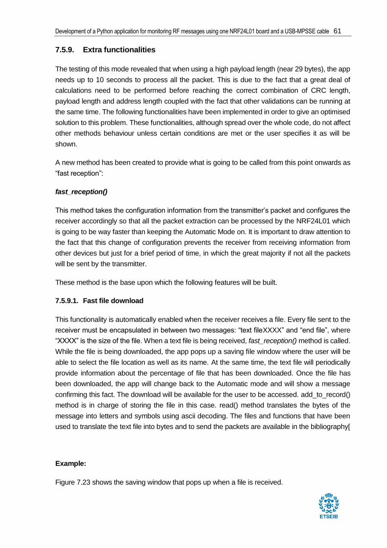
Development of a Python application for monitoring RF messages using one NRF24L01 board and a USB-MPSSE cable 61
7.5.9. Extra functionalities
The testing of this mode revealed that when using a high payload length (near 29 bytes), the app
needs up to 10 seconds to process all the packet. This is due to the fact that a great deal of
calculations need to be performed before reaching the correct combination of CRC length,
payload length and address length coupled with the fact that other validations can be running at
the same time. The following functionalities have been implemented in order to give an optimised
solution to this problem. These functionalities, although spread over the whole code, do not affect
other methods behaviour unless certain conditions are met or the user specifies it as will be
shown.
A new method has been created to provide what is going to be called from this point onwards as
“fast reception”:
fast_reception()
This method takes the configuration information from the transmitter’s packet and configures the
receiver accordingly so that all the packet extraction can be processed by the NRF24L01 which
is going to be way faster than keeping the Automatic Mode on. It is important to draw attention to
the fact that this change of configuration prevents the receiver from receiving information from
other devices but just for a brief period of time, in which the great majority if not all the packets
will be sent by the transmitter.
These method is the base upon which the following features will be built.
7.5.9.1. Fast file download
This functionality is automatically enabled when the receiver receives a file. Every file sent to the
receiver must be encapsulated in between two messages: “text fileXXXX” and “end file”, where
“XXXX” is the size of the file. When a text file is being received, fast_reception() method is called.
While the file is being downloaded, the app pops up a saving file window where the user will be
able to select the file location as well as its name. At the same time, the text file will periodically
provide information about the percentage of file that has been downloaded. Once the file has
been downloaded, the app will change back to the Automatic mode and will show a message
confirming this fact. The download will be available for the user to be accessed. add_to_record()
method is in charge of storing the file in this case. read() method translates the bytes of the
message into letters and symbols using ascii decoding. The files and functions that have been
used to translate the text file into bytes and to send the packets are available in the bibliography[
Example:
Figure 7.23 shows the saving window that pops up when a file is received.
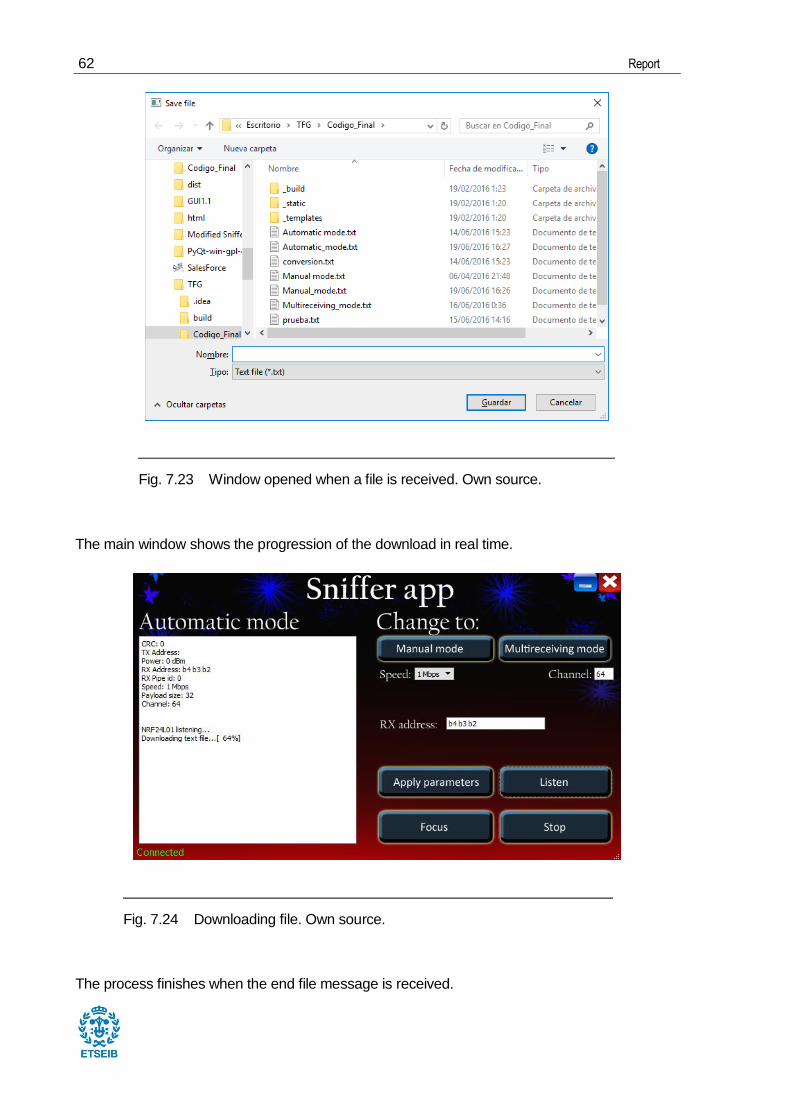
62 Report
The main window shows the progression of the download in real time.
The process finishes when the end file message is received.
Fig. 7.23 Window opened when a file is received. Own source.
Fig. 7.24 Downloading file. Own source.

Development of a Python application for monitoring RF messages using one NRF24L01 board and a USB-MPSSE cable 63
7.5.9.2. Focus
By clicking the “Focus” button, the app will focus its attention on the transmitter that sent the last
packet using fast reception. This allows almost instantaneous message reception taking profit of
the already built fast_reception() method. The messages will appear one after the other since
there is no point in providing information about the address as will be the same for every message
received.This feature is disabled when clicking “Focus” again. It is worth mentioning that this
feature has been adapted to be compatible with a wireless keyboard. Therefore, the messages
that will appear on screen after clicking on focus will be converted regarding the keyboard code.
Example:
Once the first message is received the user can click on “Focus” to focus on the last address
received. Then the application is going to translate every byte received from that address and
concatenate the messages. Every letter that the user types with the keyboard will appear on the
screen almost instantly.
Fig. 7.25 Downloading file. Own source.
Fig. 7.26 Downloaded file. Own source.
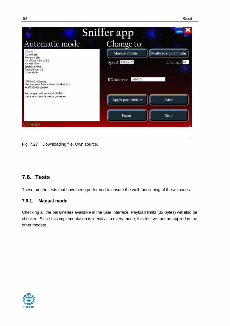
64 Report
7.6. Tests
These are the tests that have been performed to ensure the well-functioning of these modes.
7.6.1. Manual mode
Checking all the parameters available in the user interface. Payload limits (32 bytes) will also be
checked. Since this implementation is identical in every mode, this test will not be applied in the
other modes:
Fig. 7.27 Downloading file. Own source.

Development of a Python application for monitoring RF messages using one NRF24L01 board and a USB-MPSSE cable 65
Fig. 7.28 Message reception. Own source.
Fig. 7.29 Checking receiver parameters. Own source.

66 Report
Fig. 7.30 Checking transmitter parameters. Own source.

Development of a Python application for monitoring RF messages using one NRF24L01 board and a USB-MPSSE cable 67
7.6.2. Multireceiving mode:
Checking all pipes and sending two messages at the same time.

68 Report
Fig. 7.31 Checking multireceiver parameters. Own source.

Development of a Python application for monitoring RF messages using one NRF24L01 board and a USB-MPSSE cable 69
7.6.3. Automatic mode
Checking all address length possibilities from the transmitter and the receiver side. At the same
time, the CRC has been changed as well. Also check that messages are also received when
sending at the same time:
Fig. 7.32 Receiver address length: 3 bytes – Transmitter address length: 3 bytes – CRC: 2.
Own Source.
Fig. 7.33 Receiver address length: 3 bytes – Transmitter address length: 4 bytes – CRC: 1.
Own Source.
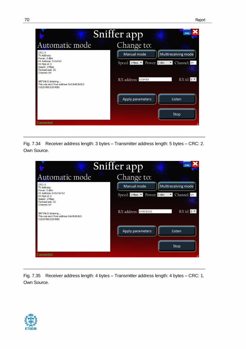
70 Report
Fig. 7.34 Receiver address length: 3 bytes – Transmitter address length: 5 bytes – CRC: 2.
Own Source.
Fig. 7.35 Receiver address length: 4 bytes – Transmitter address length: 4 bytes – CRC: 1.
Own Source.

Development of a Python application for monitoring RF messages using one NRF24L01 board and a USB-MPSSE cable 71
Fig. 7.36 Receiver address length: 4 bytes – Transmitter address length: 5 bytes – CRC: 2.
Own Source.
Fig. 7.37 Receiver address length: 5 bytes – Transmitter address length: 5 bytes – CRC: 1.
Own Source.
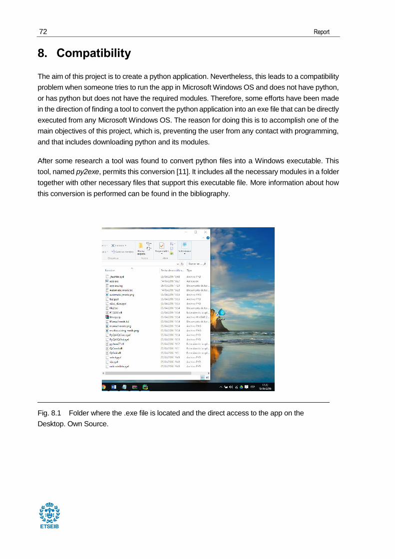
72 Report
8. Compatibility
The aim of this project is to create a python application. Nevertheless, this leads to a compatibility
problem when someone tries to run the app in Microsoft Windows OS and does not have python,
or has python but does not have the required modules. Therefore, some efforts have been made
in the direction of finding a tool to convert the python application into an exe file that can be directly
executed from any Microsoft Windows OS. The reason for doing this is to accomplish one of the
main objectives of this project, which is, preventing the user from any contact with programming,
and that includes downloading python and its modules.
After some research a tool was found to convert python files into a Windows executable. This
tool, named py2exe, permits this conversion [11]. It includes all the necessary modules in a folder
together with other necessary files that support this executable file. More information about how
this conversion is performed can be found in the bibliography.
Fig. 8.1 Folder where the .exe file is located and the direct access to the app on the
Desktop. Own Source.

Development of a Python application for monitoring RF messages using one NRF24L01 board and a USB-MPSSE cable 73
9. Future Works
Since this project has focused its efforts on how this sniffer can receive information, there are a
few aspects that have not been tackled and would be worth of further study. These are some
examples:
This sniffer can, with the app, get the configuration settings from packets sent by different
devices. It would be interesting to give the app the possibility to configure itself based on
received messages. Then, it could reconfigure different devices with different
configurations that are not receiving each other’s packets, into one single configuration
and allow these devices to catch each other’s packets.
The acknowledgement packet has not been tackled in depth since this project, although
includes a message sending feature, is mainly focused on the reception side. Therefore,
it would be interesting to send several packets waiting for the acknowledgement packet
each time so that no errors could arise in the communication process.
Other platforms and programming languages could be used in order to give this sniffer
more flexibility. For instance, with the development of an app for android, the user could
even send pictures or recordings through these devices.
Delving into the last point, it would be interesting to connect somehow this boards to the
speakers’ cable and try to send music through a smartphone or tablet.
The NRF24L01 can be used in the development of a wireless peripheral such as a mouse,
a playstation controller or even the smartphone could be used to control certain actions
on the computer.

74 Report
10. Environmental footprint
Although this is a software development project, hardware parts of this project need to be
analysed in terms of recycling and in the case of the NRF24L01, RF consequences on humans
must also be taken into account.
According to Electronics TakeBack Coalition [12], “Over 1,000 materials, including chlorinated
solvents, brominated flame retardants, PVC, heavy metals, plastics and gases, are used to make
electronic products and their components—semiconductor chips, circuit boards, display panels,
and disk drives. […] About 40% of the heavy metals in landfills, including lead, mercury and
cadmium, comes from electronic equipment discards”. These products are very damaging for the
environment and need to be properly recycled. Therefore, once the user has exploded the first
two ‘R’s (Reduce and Reuse) [13], the recycling process takes place. In order to do so, the user
must find a “Punto limpio”. Ecolec foundation has all these points mapped over the whole country
[14].
According to the “Real Decreto 1066/2001” [15], There is mainly 1 restriction for the frequency
range between 10 MHz and 10 GHz (in which our sniffer works). The average body SAR must
not be greater than 0,08 W/Kg. Considering a person whose total body mass is below average
(~50 Kg) and assuming this person is absorbing all the RF waves, if the NRF24L01 was working
in a transmitter mode at maximum power (1 mW) the SAR would be 0,00002 W/Kg. Therefore, it
can be assured that this device will never be harmful to humans in terms of RF.

Development of a Python application for monitoring RF messages using one NRF24L01 board and a USB-MPSSE cable 75
11. Costs and time planning
COSTS
Quantity Cost/Unit (€/u)
Total item
cost(€)
C232HM-DDHSL-0 1 41,31 41,31
NRF24L01+ 1 3,99 3,99
Pack Open18F4520 Package B
(board, PIC18F4520, nRF24L01+
module, connexion cables, peripherals)
3 73,75 221,25
TOTAL 266,55 €
TIME PLANNING
Hours Cost/hour (€/h) Total cost (€)
Previous study 75 60 4500
GUI building 50 60 3000
Manual mode 25 60 1500
Multireceiving mode 5 60 300
Automatic mode 50 60 3000
Trials and testing 75 60 4500
Documentation 100 60 6000
TOTAL 380 TOTAL 22800 €

76 Report
Conclusions
The aim of this project was to build a python application capable of interacting with a NRF24L01
to act as a sniffer, providing feedback from RF communications between different devices. This
main objective has been successfully achieved and other objectives focused on that direction
have also been successfully implemented within the app. Here is an overview of the relevant
points regarding this project coupled with some problems or difficulties that have been
encountered and how they have been tackled:
Standard communication between several boards have been stablished (Manual and
Multireceiving mode).
The chip allows to catch packets that match their first 3 bytes and saves almost the whole
packet inside the RX FIFO which gives free rein to packet manipulation. This operation
has a 28 bytes’ payload limitation as opposed to the 32 bytes in a regular communication.
This is because almost the whole packet is saved in the RX FIFO rather than just the
message.
Packet treatment procedures such as CRC calculation, message extraction and
retransmissions removal can be processed by the PC.
These latter points allow this application to abuse from the CRC packet validation and
extract the message from that packet together with some relevant information about the
transmitters configuration.
The last point has been proved to be a bit slow when trying to extract long messages
(near to 29 bytes).
This problem has triggered the creation of 2 functionalities (Fast file download and Focus)
that have appeared to be way faster, losing very little flexibility thanks to the fast reception
function.
The system NRF24L01 - USB/MPSSE cable – computer can properly work as a sniffer.
A completely customized GUI has been built with python modules and has been
converted into an executable file for Microsoft Windows OS. This provides easy access
to the application without having to download either python or any of its modules.
To conclude, it is worth mentioning that this application exploits all the resources that this board
provides, taking it to whole new level where not only the message can be acquired from almost
any packet, with no more information than the first 3 bytes, but also relevant information about
the transmitters configuration, which is of paramount importance for the purpose of this
application.

Aquí pot anar el títol del vostre PFC Pág. 77
Bibliography
[1]
[https://www.sparkfun.com/datasheets/Components/SMD/nRF24L01Pluss_Preliminary_Prod
uct_Specification_v1_0.pdf, 05 of June 2016]
[2]
[http://www.ftdichip.com/Support/Documents/DataSheets/Cables/DS_C232HM_MPSSE_CA
BLE.PDF, 05 of June 2016]
[3] [http://m222982.blogspot.com.es/2013/03/ftdi-mpsse-mode-library-part-i-spi.html, 13 of
June 2016]
[4] [https://github.com/micropython/micropython/tree/master/drivers/nrf24l01, 13 of June
2016]
[5] [https://www.riverbankcomputing.com/software/pyqt/download
[6] [http://pyqt.sourceforge.net/Docs/PyQt4/classes.html 4 of May 2016]
[7] [http://www.zlib.net/crc_v3.txt, 30 of April 2016]
[8] [https://en.wikipedia.org/wiki/Cyclic_redundancy_check, 30 of April 2016]
[9] [http://www.lammertbies.nl/comm/info/crc-calculation.html, 30 of April 2016]
[10] [http://yveaux.blogspot.com.es/2014/07/nrf24l01-sniffer-part-1.html, 13 of June 2016]
[11] [http://www.py2exe.org/index.cgi/Tutorial, 6 of June 2016]
[12] [http://www.electronicstakeback.com/how-to-recycle-electronics, 16 of June 2016]
[13] [http://www.consumer.es/web/es/medio_ambiente/urbano/2012/09/10/212515.php, 16 of
June 2016]
[14] [http://www.ecolec.es, 16 of June 2016]
[15] [https://www.boe.es/diario_boe/txt.php?id=BOE-A-2001-18256, 16 of June 2016]

Pág. 78 Memoria
Figures
3.1 [http://www.waveshare.com/product/nrf24l01-rf-board-b.htm, 12 of March 2016]
3.2 [http://www.ftdichip.com/Products/Cables/USBMPSSE.htm, 20 of March 2016]
3.3 [http://www.waveshare.com/w/upload/0/07/NRF24L01-RF-Board-UserManual.pdf, 20 of
March 2016]
3.4 [http://www.ftdichip.com/Products/Cables/USBMPSSE.htm, 20 of March 2016]
5.1 [http://www.waveshare.com/w/upload/4/45/NRF24L01P.pdf, 04 of May 2016]
5.2 [http://www.waveshare.com/w/upload/4/45/NRF24L01P.pdf, 04 of May 2016]
5.3 [http://www.waveshare.com/w/upload/4/45/NRF24L01P.pdf, 04 of May 2016]
Top Related