


Languages
Pages
Legal


DETERMINING DENSITY OF COMPACTED BITUMINOUS MIXTURES TXDOT DESIGNATION: TEX-207-F
CONSTRUCTION DIVISION 1 – 21 EFFECTIVE DATE: NOVEMBER 2016
Test Procedure for
DETERMINING DENSITY OF COMPACTED
BITUMINOUS MIXTURES
TxDOT Designation: Tex-207-F
Effective Date: November 2016
1. SCOPE
1.1 This test method determines the bulk specific gravity (Ga) of compacted bituminous
mixture specimens. Use the Ga of the specimens to calculate the degree of densification
or percent compaction of the bituminous mixture.
1.2 Refer to Table 1 for Superpave and conventional mix nomenclature equivalents. Replace
conventional nomenclature with the Superpave nomenclature when required.
Table 1—Nomenclatures and Definitions
Nomenclatures
Definitions
Conventional Superpave
AC - Asphalt Content
Ag Ps Percent by weight of aggregate in the mixture
As Pb Percent by weight of asphalt binder in the mixture
Ga Gmb Bulk specific gravity of compacted specimens
Ge Gse Effective specific gravity of the combined aggregates
Gr Gmm Theoretical maximum specific gravity
Grc Gmm Theoretical maximum specific gravity corrected for water absorption during
test
Gs Gb Specific gravity of the asphalt binder determined at 77°F (25°C)
Gt Gmax-theo Calculated theoretical maximum specific gravity of the mixture at the
specified AC
1.3 The values given in parentheses (if provided) are not standard and may not be exact
mathematical conversions. Use each system of units separately. Combining values from
the two systems may result in nonconformance with the standard.
DETERMINING DENSITY OF COMPACTED BITUMINOUS MIXTURES TXDOT DESIGNATION: TEX-207-F
CONSTRUCTION DIVISION 2 – 21 EFFECTIVE DATE: NOVEMBER 2016
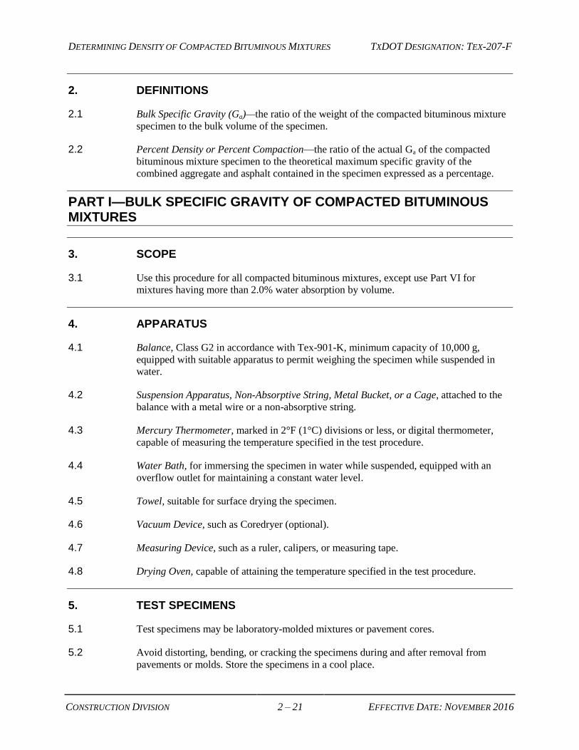
2. DEFINITIONS
2.1 Bulk Specific Gravity (Ga)—the ratio of the weight of the compacted bituminous mixture
specimen to the bulk volume of the specimen.
2.2 Percent Density or Percent Compaction—the ratio of the actual Ga of the compacted
bituminous mixture specimen to the theoretical maximum specific gravity of the
combined aggregate and asphalt contained in the specimen expressed as a percentage.
PART I—BULK SPECIFIC GRAVITY OF COMPACTED BITUMINOUS MIXTURES
3. SCOPE
3.1 Use this procedure for all compacted bituminous mixtures, except use Part VI for
mixtures having more than 2.0% water absorption by volume.
4. APPARATUS
4.1 Balance, Class G2 in accordance with Tex-901-K, minimum capacity of 10,000 g,
equipped with suitable apparatus to permit weighing the specimen while suspended in
water.
4.2 Suspension Apparatus, Non-Absorptive String, Metal Bucket, or a Cage, attached to the
balance with a metal wire or a non-absorptive string.
4.3 Mercury Thermometer, marked in 2°F (1°C) divisions or less, or digital thermometer,
capable of measuring the temperature specified in the test procedure.
4.4 Water Bath, for immersing the specimen in water while suspended, equipped with an
overflow outlet for maintaining a constant water level.
4.5 Towel, suitable for surface drying the specimen.
4.6 Vacuum Device, such as Coredryer (optional).
4.7 Measuring Device, such as a ruler, calipers, or measuring tape.
4.8 Drying Oven, capable of attaining the temperature specified in the test procedure.
5. TEST SPECIMENS
5.1 Test specimens may be laboratory-molded mixtures or pavement cores.
5.2 Avoid distorting, bending, or cracking the specimens during and after removal from
pavements or molds. Store the specimens in a cool place.

DETERMINING DENSITY OF COMPACTED BITUMINOUS MIXTURES TXDOT DESIGNATION: TEX-207-F
CONSTRUCTION DIVISION 3 – 21 EFFECTIVE DATE: NOVEMBER 2016
5.3 Laboratory-Molded Specimens:
5.3.1 Measure and record the specimen height to the nearest 1/16 in.
5.4 Pavement Cores:
5.4.1 For cores with uneven surfaces, follow the instructions in Sections 5.4.3–5.4.12.
5.4.2 For cores with level surfaces, measure the untrimmed core height to the nearest 1/16 in.
and proceed to Section 5.4.8.
Note 1—When measuring the untrimmed core height, do not include foreign matter.
Foreign matter is material extraneous to the pavement layer being tested; examples
include another paving layer, such as hot mix, surface treatment, subgrade, or base
material.
5.4.3 On the top surface of the core, mark the apparent thinnest location with a permanent
marker or paint pen.
5.4.4 Make 3 more marks around the perimeter of the core, at 90, 180, and 270 degrees from
the mark made in Section 5.4.3.
5.4.5 Measure the height of the core at the marked locations. Refer to Note 1.
5.4.6 Take additional measurements around the core if the measurements taken in Section 5.4.5
vary by more than 1/4 in. Mark the location of the additional measurements.
5.4.7 Average the measurements and record the untrimmed core height to the nearest 1/16 in.
5.4.8 Remove visually evident foreign matter from the core with a saw or by any other
satisfactory means.
5.4.9 Ensure that the sample size and number of samples conform to the requirements of
Tex-222-F.
5.4.10 Trim the bottom or top of the core only when necessary to remove any foreign matter and
to provide a level and smooth surface for testing.
5.4.11 Trim the minimum amount of core necessary, but no more than 1/2 in.
Note 2—Do not trim the core if the surface is level and there is not foreign matter
bonded to the surface of the core.
5.4.12 Measure and record the trimmed core height to the nearest 1/16 in.
6. PROCEDURES
6.1 For specimens containing moisture, follow the instructions in Sections 6.2–6.9. For
laboratory-molded specimens, perform the instructions in Sections 6.3–6.9.
6.2 Place the specimen in an oven with the flat side of the specimen on a flat surface to
complete the drying process. Oven-dry the specimen for a minimum of 2 hr. at a
DETERMINING DENSITY OF COMPACTED BITUMINOUS MIXTURES TXDOT DESIGNATION: TEX-207-F
CONSTRUCTION DIVISION 4 – 21 EFFECTIVE DATE: NOVEMBER 2016
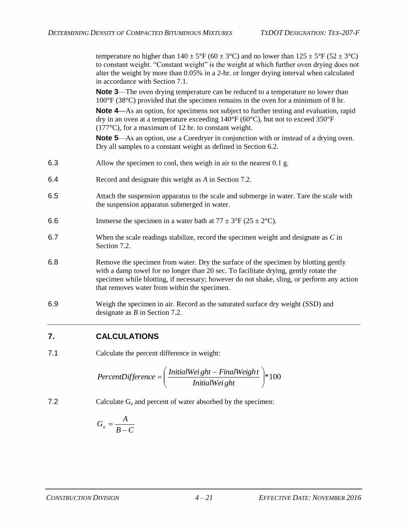
temperature no higher than 140 ± 5°F (60 ± 3°C) and no lower than 125 ± 5°F (52 ± 3°C)
to constant weight. “Constant weight” is the weight at which further oven drying does not
alter the weight by more than 0.05% in a 2-hr. or longer drying interval when calculated
in accordance with Section 7.1.
Note 3—The oven drying temperature can be reduced to a temperature no lower than
100°F (38°C) provided that the specimen remains in the oven for a minimum of 8 hr.
Note 4—As an option, for specimens not subject to further testing and evaluation, rapid
dry in an oven at a temperature exceeding 140°F (60°C), but not to exceed 350°F
(177°C), for a maximum of 12 hr. to constant weight.
Note 5—As an option, use a Coredryer in conjunction with or instead of a drying oven.
Dry all samples to a constant weight as defined in Section 6.2.
6.3 Allow the specimen to cool, then weigh in air to the nearest 0.1 g.
6.4 Record and designate this weight as A in Section 7.2.
6.5 Attach the suspension apparatus to the scale and submerge in water. Tare the scale with
the suspension apparatus submerged in water.
6.6 Immerse the specimen in a water bath at 77 ± 3°F (25 ± 2°C).
6.7 When the scale readings stabilize, record the specimen weight and designate as C in
Section 7.2.
6.8 Remove the specimen from water. Dry the surface of the specimen by blotting gently
with a damp towel for no longer than 20 sec. To facilitate drying, gently rotate the
specimen while blotting, if necessary; however do not shake, sling, or perform any action
that removes water from within the specimen.
6.9 Weigh the specimen in air. Record as the saturated surface dry weight (SSD) and
designate as B in Section 7.2.
7. CALCULATIONS
7.1 Calculate the percent difference in weight:
100*
ghtInitialWei
tFinalWeighghtInitialWeiferencePercentDif
7.2 Calculate Ga and percent of water absorbed by the specimen:
CB
AGa

DETERMINING DENSITY OF COMPACTED BITUMINOUS MIXTURES TXDOT DESIGNATION: TEX-207-F
CONSTRUCTION DIVISION 5 – 21 EFFECTIVE DATE: NOVEMBER 2016
Where:
Ga = bulk specific gravity
A = weight of dry specimen in air, g
B = weight of the SSD specimen in air, g
C = weight of the specimen in water, g.
100B A
Percent absorptionB C
7.3 If the percent absorption exceeds 2%, use the preferred method, Part VI.
PART II—BULK SPECIFIC GRAVITY OF COMPACTED BITUMINOUS MIXTURES USING PARAFFIN
8. SCOPE
8.1 The paraffin method is no longer an accepted process.
8.2 Refer to Part VI of this test procedure for absorptive mixtures (those having more than
2.0% water absorption).
PART III—DETERMINING IN-PLACE DENSITY OF COMPACTED BITUMINOUS MIXTURES (NUCLEAR METHOD)
9. SCOPE
9.1 Use this procedure to determine the in-place density of compacted bituminous mixtures
using a nuclear density gauge.
10. APPARATUS
10.1 Nuclear Density Gauge.
10.2 Portable Reference Standard.
10.3 Calibration Curves for the Nuclear Gauge.
10.4 Scraper Plate and Drill Rod Guide.
10.5 Drill Rod and Driver or Hammer.
10.6 Shovel, Sieve, Trowel, or Straightedge and Miscellaneous Hand Tools.
10.7 Gauge Logbook.
DETERMINING DENSITY OF COMPACTED BITUMINOUS MIXTURES TXDOT DESIGNATION: TEX-207-F
CONSTRUCTION DIVISION 6 – 21 EFFECTIVE DATE: NOVEMBER 2016
11. STANDARDIZATION
11.1 To standardize the nuclear density gauge, turn on the apparatus and allow it to stabilize.
Note 6—Follow the manufacturer’s recommendations in order to ascertain the most
stable and consistent results.
11.2 Perform standardization with the apparatus located at least 25 ft. (8 m) away from other
sources of radioactivity. Clear the area of large masses or other items that may affect the
reference count rate.
Note 7—The preferred location for standardization checking is the pavement location
tested. This is the best method for determining day-to-day variability in the equipment.
11.3 Take a minimum of 4 repetitive readings using Table 2 at the normal measurement
period, and determine the average of these readings.
Note 8—One measurement period of 4 or more times the normal period is acceptable if
available on the apparatus. This constitutes one standardization check.
11.4 Detect the total number of gammas during the period by determining the count per
measurement period. Correct the displayed value for any prescaling built into the
instrument. Record this corrected value as Ns.
Note 9—The prescale value (F) is a divisor, which reduces the actual value for the
purpose of display. The manufacturer will supply this value if other than 1.0.
11.5 Use the value of Ns to determine the count ratios for the current day's use of the
instrument.
Note 10—Perform another standardization check if for any reason the measured density
becomes suspect during the day's use.
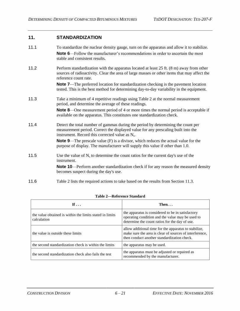
11.6 Table 2 lists the required actions to take based on the results from Section 11.3.
Table 2—Reference Standard
If . . . Then. . .
the value obtained is within the limits stated in limits
calculation
the apparatus is considered to be in satisfactory
operating condition and the value may be used to
determine the count ratios for the day of use.
the value is outside these limits
allow additional time for the apparatus to stabilize,
make sure the area is clear of sources of interference,
then conduct another standardization check.
the second standardization check is within the limits the apparatus may be used.
the second standardization check also fails the test the apparatus must be adjusted or repaired as
recommended by the manufacturer.
DETERMINING DENSITY OF COMPACTED BITUMINOUS MIXTURES TXDOT DESIGNATION: TEX-207-F
CONSTRUCTION DIVISION 7 – 21 EFFECTIVE DATE: NOVEMBER 2016
12. CALCULATIONS
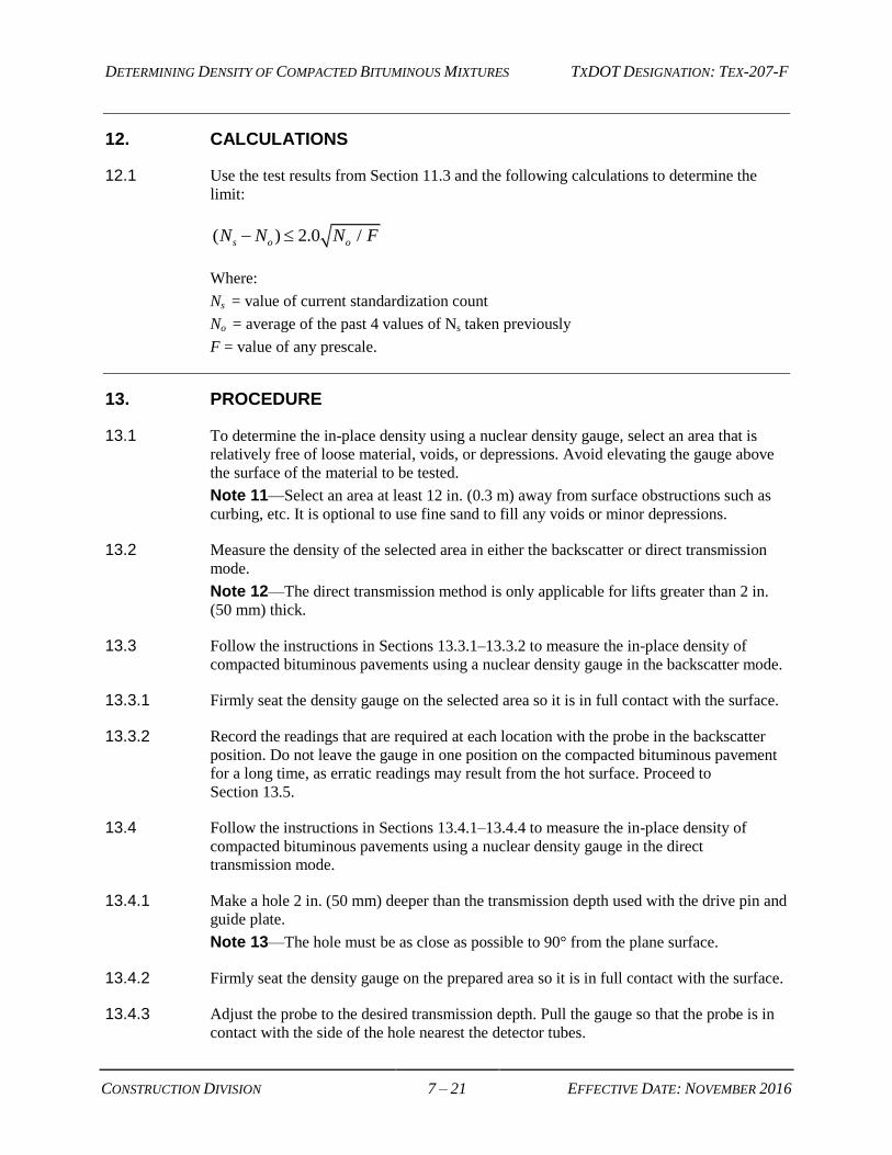
12.1 Use the test results from Section 11.3 and the following calculations to determine the
limit:
( ) 2.0 /s o oN N N F
Where:
Ns = value of current standardization count
No = average of the past 4 values of Ns taken previously
F = value of any prescale.
13. PROCEDURE
13.1 To determine the in-place density using a nuclear density gauge, select an area that is
relatively free of loose material, voids, or depressions. Avoid elevating the gauge above
the surface of the material to be tested.
Note 11—Select an area at least 12 in. (0.3 m) away from surface obstructions such as
curbing, etc. It is optional to use fine sand to fill any voids or minor depressions.
13.2 Measure the density of the selected area in either the backscatter or direct transmission
mode.
Note 12—The direct transmission method is only applicable for lifts greater than 2 in.
(50 mm) thick.
13.3 Follow the instructions in Sections 13.3.1–13.3.2 to measure the in-place density of
compacted bituminous pavements using a nuclear density gauge in the backscatter mode.
13.3.1 Firmly seat the density gauge on the selected area so it is in full contact with the surface.
13.3.2 Record the readings that are required at each location with the probe in the backscatter
position. Do not leave the gauge in one position on the compacted bituminous pavement
for a long time, as erratic readings may result from the hot surface. Proceed to
Section 13.5.
13.4 Follow the instructions in Sections 13.4.1–13.4.4 to measure the in-place density of
compacted bituminous pavements using a nuclear density gauge in the direct
transmission mode.
13.4.1 Make a hole 2 in. (50 mm) deeper than the transmission depth used with the drive pin and
guide plate.
Note 13—The hole must be as close as possible to 90° from the plane surface.
13.4.2 Firmly seat the density gauge on the prepared area so it is in full contact with the surface.
13.4.3 Adjust the probe to the desired transmission depth. Pull the gauge so that the probe is in
contact with the side of the hole nearest the detector tubes.

DETERMINING DENSITY OF COMPACTED BITUMINOUS MIXTURES TXDOT DESIGNATION: TEX-207-F
CONSTRUCTION DIVISION 8 – 21 EFFECTIVE DATE: NOVEMBER 2016
13.4.4 Measure and record the readings required for each location for the particular type of
gauge used. Proceed to Section 13.5.
13.5 Use one of the following methods to determine the in-place density.
13.5.1 Divide the field counts by the standard counts.
OR
13.5.2 Use the appropriate calibration curves, if necessary.
Note 14—Most models are now programmable to provide direct reading of the nuclear
density or percent compaction.
13.6 Take cores or sections of the pavement from the same area selected for the nuclear tests
when correlating the nuclear density to the actual density of the compacted material.
13.7 Measure the Ga of the cores or samples taken from the selected area tested for density as
described in Part I or Part VI. Establish a correlation factor using a minimum of 7 core
densities and 7 nuclear densities. Adjust the nuclear density readings using this
correlation factor to correlate with the actual Ga determined through laboratory testing.
Note 15—When testing thin lifts in the backscatter mode, the influence of underlying
strata with varying densities may render this procedure impractical without special
planning. Most manuals for the nuclear gauge describe the various methods to use with
thin lifts.
13.8 Make correlations as described in Section 13.6 and compare the correlated nuclear
density to the Gr or Grc of the mixture when controlling in-place density with the nuclear
gauge. Calculate the percent density or directly read from programmable models to
determine air-void content.
PART IV—ESTABLISHING ROLLER PATTERNS (CONTROL STRIP METHOD)
14. SCOPE
14.1 Use this procedure to establish roller patterns for bituminous pavement.
15. APPARATUS
15.1 Nuclear Density Gauge.
15.2 Electrical Impedance (Nonnuclear) Density Measurement Gauge (Optional).
15.3 Portable Reference Standard.
15.4 Calibration Curves for the Nuclear Gauge.
15.5 Scraper Plate and Drill Rod Guide.
DETERMINING DENSITY OF COMPACTED BITUMINOUS MIXTURES TXDOT DESIGNATION: TEX-207-F
CONSTRUCTION DIVISION 9 – 21 EFFECTIVE DATE: NOVEMBER 2016
15.6 Drill Rod and Driver or Hammer.
15.7 Shovel, Sieve, Trowel, or Straightedge and Miscellaneous Hand Tools.
15.8 Gauge Logbook.
16. PROCEDURE
16.1 To establish roller patterns (control strip method), refer to the gauge manufacturer’s
instructions for operating the density gauge.
Note 16—Standardize the equipment at the start of each day’s use as described in
Part III when using a nuclear density gauge.
16.2 Establish a control strip approximately 300 ft. (90 m) long and at least 12 ft. (3.5 m) wide
or the width of the paving machine. Select 3 test sites.
Note 17—Avoid areas near edges or overlap of successive passes of the rollers.
16.3 Allow the roller to complete a minimum of 2 coverages of the entire control strip before
checking the density. Perform density tests at the 3 test sites selected. Record the results.
Mark each test site very carefully so that subsequent tests made are in the same position
and location. Use a colored marker keel to outline the gauge before taking the readings.
Take the tests as quickly as possible and release rollers to complete additional coverage
to prevent cooling of unrolled areas.
16.4 Repeat the density tests at the previously marked test sites. Continue this process of
rolling and testing until there is no significant increase in density. Try several different
combinations of equipment, and numbers of passes with each combination, to determine
the most effective rolling pattern.
Note 18—In-place density determined with roadway cores is the final measure of rolling
pattern effectiveness.
16.5 Construct another section, without interruption, using the roller patterns and number of
coverages determined by the control strip after completion of the control strip tests. Take
random density tests on this section to verify the results from the control strip.
Note 19—It may be possible to reduce the required coverages based on these tests.
16.6 Make density tests for job control in accordance with the Guide Schedule of Sampling
and Testing or as often as necessary, when some changes in the compacted material
indicate the need.
17. NOTES
17.1 Visual observation of the surface being compacted is a very important part of this
procedure. Cease rolling and get an evaluation of the roller pattern if obvious signs of
distress develop, such as cracking, shoving, etc. Structural failures due to over-
compaction will cause the density tests to indicate the need for more compaction.
Observe closely and take particular care when using vibratory rollers, since they are more
likely to produce over-compaction in the material.
DETERMINING DENSITY OF COMPACTED BITUMINOUS MIXTURES TXDOT DESIGNATION: TEX-207-F
CONSTRUCTION DIVISION 10 – 21 EFFECTIVE DATE: NOVEMBER 2016
17.2 Use the minimum test time allowed by the particular gauge when measuring density on
hot material, since the gauge may display erratic results if overheated.
17.3 Exercise particular care to clean the bottom of the gauge after using it on asphalt
pavement.
17.4 Use the correlation procedures outlined in Part III, Section 13.7 when using specified
density and rolling patterns with a nuclear density gauge.
17.5 This procedure provides a general guide to establish roller patterns. Follow the
manufacturer’s instruction manual furnished with the particular density gauge for specific
operation of that gauge. This is essential, since several different models and different
brands are in standard use by the Department.
17.6 Nuclear gauges and the user of the nuclear gauges must meet all requirements of the
Department’s radioactive material license, “Nuclear Gauge Operating Procedures,” and
the Texas Rules for Control of Radiation.
PART V—DETERMINING MAT SEGREGATION USING A DENSITY-TESTING GAUGE
18. SCOPE
18.1 Use this procedure to identify segregation in bituminous pavements after placement on
the roadway using a density-testing gauge.
19. APPARATUS
19.1 Nuclear Density Gauge.
19.2 Thin Lift Density Gauge (Optional).
19.3 Electrical Impedance (Nonnuclear) Measurement Gauge (Optional).
19.4 Measuring Tape (Optional).
20. REPORT FORMS
20.1 Use Segregation Density Profile Form to identify segregation in a pavement section.
21. PROCEDURE
21.1 Refer to the manufacturer’s instructions for operating the density gauge.
Note 20—It is not necessary to calibrate the gauge to the mix.
21.2 Profile a 50-ft. (15-m) section of the bituminous pavement.
DETERMINING DENSITY OF COMPACTED BITUMINOUS MIXTURES TXDOT DESIGNATION: TEX-207-F
CONSTRUCTION DIVISION 11 – 21 EFFECTIVE DATE: NOVEMBER 2016
21.3 When profiling a location where the paver stopped for more than 60 seconds, perform the
instructions in Sections 21.3.1–21.3.3.
21.3.1 Identify the location where the paver stopped paving, such as sporadic mix delivery.
21.3.2 Move approximately 10 ft. (3 m) behind the location where the paver stopped paving, and
mark and record this location as the beginning of the profile section.
21.3.3 Proceed to Section 21.6.
21.4 When profiling a random location, randomly select an area, then choose an area with
visible segregation, if possible. Proceed to Section 21.6.
21.5 When profiling an area with segregation of longitudinal streaking greater than the profile
length, perform the instructions in Sections 21.5.1–21.5.5.
21.5.1 Profile the area at an angle in a diagonal direction.
21.5.2 Start the profile with a transverse offset of 2 ft. (0.6 m) from the center of the longitudinal
streak.
21.5.3 End profile with a transverse offset of 2 ft. (0.6 m) on the opposite side of the
longitudinal streak.
21.5.4 Do not start or end a profile less than 1 ft. (0.3 m) from the pavement edge.
21.5.5 Proceed to Section 21.7.
21.6 Determine the transverse offset 2 ft. (0.6 m) or more from the pavement edge. Take
density readings in a longitudinal direction and do not vary from this line. Visually
observe the mat and note the surface texture in the section and the location of any visible
segregated areas. Take additional readings along the transverse offset in areas with
visible segregation. Include any visually segregated areas in the profile.
21.7 After completion of the final rolling patterns, position the density gauge at the identified
location.
21.7.1 Use of a Nuclear Density Gauge:
21.7.1.1 Take three 1-min. readings (minimum time length, longer readings can be used) in
backscatter mode when using a nuclear density gauge at each random sample location.
21.7.1.2 It is optional to use fine sand passing the No. 40 sieve size to fill any voids without
elevating the gauge above the rest of the mat.
21.7.2 Use of an Electrical Impedance Gauge:
21.7.2.1 Take 2 readings; it is not necessary to move the gauge between readings.
21.8 Record the in-place density gauge readings.

DETERMINING DENSITY OF COMPACTED BITUMINOUS MIXTURES TXDOT DESIGNATION: TEX-207-F
CONSTRUCTION DIVISION 12 – 21 EFFECTIVE DATE: NOVEMBER 2016
21.9 Average the readings before moving the density gauge. Compare each individual reading
to the average. Discard any single readings that vary more than 1 pcf (16 kg/m3) from the
average. Take additional readings to replace the discarded readings until all the readings
are within 1 pcf (16 kg/m3) of the average.
21.10 Move the density gauge approximately 5 ft. (1.5 m) forward in the direction of the paving
operation. Take an additional set of readings at any location with visible segregation in
between the 5 ft. (1.5 m) distance.
21.11 Repeat the instructions in Sections 21.7–21.10. Complete a minimum of 10 sets of
readings.
Note 21—Use a nuclear density gauge to verify impedance gauge readings whenever
readings from an impedance gauge may not be accurate.
21.12 Determine the average density from all locations.
21.13 Determine the difference between the highest and lowest average density.
21.14 Determine the difference between the average and lowest average density.
21.15 Record the data using the Example Segregation Profile Worksheet.
PART VI—BULK SPECIFIC GRAVITY OF COMPACTED BITUMINOUS MIXTURES USING THE VACUUM METHOD
22. SCOPE
22.1 Use this procedure to determine the Ga of compacted bituminous mixtures using the
vacuum device. This procedure is applicable for mixtures having more than 2.0% water
absorption by volume.
23. APPARATUS
23.1 Specialized Vacuum Sealing Device.
23.2 Balance, Class G2 in accordance with Tex-901-K, minimum capacity of 10,000 g,
equipped with suitable apparatus to permit weighing of the specimen while suspended in
water.
23.3 Suspension Apparatus, Non-Absorptive String, Metal Bucket, or Cage, attached to the
balance with a metal wire or a non-absorptive string.
23.4 Mercury Thermometer, marked in 2°F (1°C) divisions or less, or digital thermometer,
capable of measuring the temperature specified in the test procedure.
23.5 Water Bath, for immersing the specimen in water while suspended from a scale, equipped
with an overflow outlet for maintaining a constant water level.

DETERMINING DENSITY OF COMPACTED BITUMINOUS MIXTURES TXDOT DESIGNATION: TEX-207-F
CONSTRUCTION DIVISION 13 – 21 EFFECTIVE DATE: NOVEMBER 2016
23.6 Vacuum Device, such as Coredryer (optional).
23.7 Measuring Device, such as a ruler, calipers, or measuring tape.
24. TEST SPECIMENS
24.1 Test specimens may be laboratory-molded mixtures or pavement cores.
24.2 Avoid distorting, bending or cracking the specimens during and after removal from
pavements or molds. Store the specimens in a cool place
24.3 Laboratory-Molded Specimens:
24.3.1 Measure and record the specimen height to the nearest 1/16 in.
24.4 Pavement Cores:
24.4.1 For cores with uneven surfaces, follow the instructions in Sections 24.4.3–24.4.12.
24.4.2 For cores with level surfaces, measure the untrimmed core height to the nearest 1/16 in.
and proceed to Section 24.4.8.
Note 22—When measuring the untrimmed core height, do not include foreign matter.
Foreign matter is material extraneous to the pavement layer being tested; examples
include another paving layer, such as hot mix, surface treatment, subgrade, or base
material.
24.4.3 On the top surface of the core, mark the apparent thinnest location with a permanent
marker or paint pen.
24.4.4 Make 3 more marks around the perimeter of the core, at 90, 180, and 270 degrees from
the mark made in Section 24.4.3.
24.4.5 Measure the height of the core at the marked locations. Refer to Note 21.
24.4.6 Take additional measurements around the core if the measurements taken in
Section 24.4.5 vary by more than 1/4 in. Mark the location of the additional
measurements.
24.4.7 Average the measurements and record the untrimmed core height to the nearest 1/16 in.
24.4.8 Remove visually evident foreign matter from the core with a saw or by any other
satisfactory means.
24.4.9 Ensure that the sample size and number of samples conform to the requirements of
Tex-222-F.
24.4.10 Trim the bottom or top of the core only when necessary to remove any foreign matter and
to provide a level and smooth surface for testing.
24.4.11 Trim the minimum amount of core necessary, but no more than 1/2 in.
DETERMINING DENSITY OF COMPACTED BITUMINOUS MIXTURES TXDOT DESIGNATION: TEX-207-F
CONSTRUCTION DIVISION 14 – 21 EFFECTIVE DATE: NOVEMBER 2016
Note 23—Do not trim the core if the surface is level and there is not foreign matter
bonded to the surface of the core.
24.4.12 Measure and record the trimmed core height to the nearest 1/16 in.
25. MATERIALS
25.1 Use a supply of large and small specialized polymer bags as recommended by the
manufacturer.
26. PROCEDURES
26.1 Vacuum Sealing Device Setup:
26.1.1 Set the vacuum timer.
Note 24—The manufacturer calibrates the vacuum pump timer setting and exhaust at the
factory to eliminate drift and variability due to the sealing process. The vacuum pump
operates for approximately 1 min. Contact the manufacturer for adjustments if the
vacuum pump stops before this time has elapsed.
26.1.2 Set the sealing bar timer in accordance with the vacuum device manufacturer’s
recommendations.
Note 25—Inspect the seal quality after the first sealing operation. Reduce the setting if
the polymer bag stretches or burns. Increase the setting if the seal is not complete or the
bag easily separates.
26.2 Determine the Ga of Compacted Bituminous Mixtures:
26.2.1 Perform the instructions in Sections 26.2.2–26.2.3 for specimens containing moisture.
Proceed to Section 26.2.4 for laboratory-molded specimens.
26.2.2 Proceed to Section 26.2.3 or, as an option, pre-dry the specimen using a Coredryer or air
dry to remove excess moisture.
26.2.3 Place the specimen in an oven with the flat side of the specimen on a flat surface. Oven-
dry the specimen for a minimum of 2 hr. at a temperature no higher than 140 ± 5°F
(60 ± 3°C) and no lower than 125 ± 5°F (52 ± 3°C) to a constant weight. “Constant
weight” is the weight at which further oven drying does not alter the weight by more than
0.05% in a 2-hr. or longer drying interval in accordance with Section 7.1. Refer to Part I,
Notes 3 and 4.
26.2.4 Allow the specimen to cool to room temperature, and then weigh in air to the nearest
0.1 g. Record and designate this weight as A in Section 27.1. Proceed to Section 26.2.7.
26.2.5 Perform the instructions in Section 26.2.7 if testing laboratory-molded specimens or dry
specimens.
DETERMINING DENSITY OF COMPACTED BITUMINOUS MIXTURES TXDOT DESIGNATION: TEX-207-F
CONSTRUCTION DIVISION 15 – 21 EFFECTIVE DATE: NOVEMBER 2016
26.2.6 Allow laboratory-molded specimens or thoroughly dry specimens to cool to room
temperature, then weigh the specimen in air to the nearest 0.1 g. Record and designate
this weight as A in Section 27.1. Proceed to Section 26.2.7.
26.2.7 Open the lid of the vacuum device. Stack or remove rectangular spacer plates in the
vacuum chamber of the vacuum device so there is adequate space for the test specimen.
26.2.8 Place a sliding plate in the vacuum chamber on top of the spacer plates away from the
seal bar.
Note 26—Place the sliding plate in the chamber to reduce friction during the sealing
operation.
26.2.9 Select and use a large or small polymer bag, as recommended by the manufacturer, to
seal the specimen.
26.2.10 Weigh the selected polymer bag and record and designate this weight as B in
Section 27.1.
26.2.11 Determine the Polymer Bag Correction Factor (CF):
26.2.11.1 Calculate the ratio, R, by dividing the weight of the specimen by the weight of the bag.
26.2.11.2 Use the CF Table provided in the manufacturer‘s operator guide.
26.2.11.3 Look up the calculated R-value and record and designate the corresponding correction
factor from the table as CF in Section 27.1.
26.2.12 Vacuum Seal the Specimens:
26.2.12.1 Place the bag inside the chamber.
26.2.12.2 Place the specimen in the polymer bag, carefully avoiding puncturing or tearing the bag.
26.2.12.3 Center the core in the bag, leaving approximately 1 in. (25.4 mm) of slack on the
backside.
26.2.12.4 Position the bag so that approximately 1 in. (25.4 mm) of the open end is evenly against
the sealing bar.
26.2.12.5 Close the lid of the vacuum device and hold firmly for 2–3 sec.
Note 27—The vacuum pump will start, and the lid will stay closed on its own. The
vacuum gauge will read less than 28 in. (50 mm) Hg.
26.2.12.6 The lid of the vacuum device will automatically open upon completion of the sealing
process. Carefully remove the sealed specimen from the chamber. Gently pull on the
polymer bag to ensure the seal is tightly conformed to the specimen. Return to the
instructions in Section 26.2.10 if the seal is not tightly conformed to the specimen.
Note 28—A loose seal may be an indication of a leak.
26.2.13 Determine the type of apparatus to use to weigh the samples suspended in water.
DETERMINING DENSITY OF COMPACTED BITUMINOUS MIXTURES TXDOT DESIGNATION: TEX-207-F
CONSTRUCTION DIVISION 16 – 21 EFFECTIVE DATE: NOVEMBER 2016
26.2.14 Attach the apparatus to the scale and submerge in water. Tare the scale with the apparatus
submerged in water.
26.2.15 Completely submerge the sealed specimen in water at 77 ± 3°F (25 ± 2°C) and record the
weight of the specimen in the bag. Weigh the sealed specimen in water. Record the
weight to the nearest 0.1 g when the scale reading stabilizes. Designate this weight as C
in Section 32.1.
Note 29—Do not allow the polymer bag to touch the sides of the water bath.
26.2.16 Remove the specimen from the polymer bag and reweigh the specimen in air. Compare
this weight to the weight recorded for A in Section 26.2.1 or 26.2.5. If the difference in
weight is greater than 5 g, a leak may have occurred. Dry the sample to a constant weight
and repeat the procedure using a new polymer bag.
26.3 Do not use the test results calculated in this test procedure using the vacuum device if this
method produces a Ga that is higher than the Ga calculated in Part I.
Note 30—Use the results calculated in Part I of this method in this case.
27. CALCULATIONS
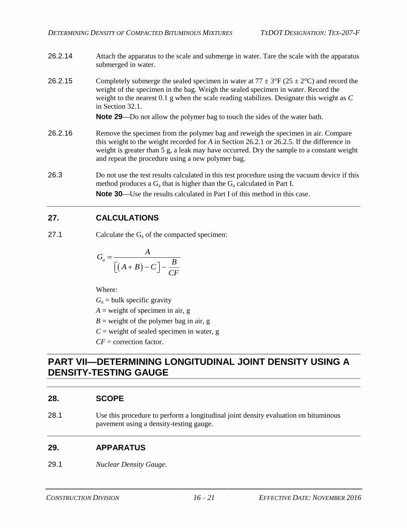
27.1 Calculate the Ga of the compacted specimen:
a
AG
BA B C
CF
Where:
Ga = bulk specific gravity
A = weight of specimen in air, g
B = weight of the polymer bag in air, g
C = weight of sealed specimen in water, g
CF = correction factor.
PART VII—DETERMINING LONGITUDINAL JOINT DENSITY USING A DENSITY-TESTING GAUGE
28. SCOPE
28.1 Use this procedure to perform a longitudinal joint density evaluation on bituminous
pavement using a density-testing gauge.
29. APPARATUS
29.1 Nuclear Density Gauge.
DETERMINING DENSITY OF COMPACTED BITUMINOUS MIXTURES TXDOT DESIGNATION: TEX-207-F
CONSTRUCTION DIVISION 17 – 21 EFFECTIVE DATE: NOVEMBER 2016
29.2 Thin Lift Density Gauge (Optional).
29.3 Electrical Impedance (Nonnuclear) Density Measurement Gauge (Optional).
29.4 Measuring Tape (Optional).
30. FORMS
30.1 Longitudinal Joint Density Profile Form.
31. PROCEDURES
31.1 Perform a Longitudinal Joint Density Using a Density-Testing Gauge:
31.1.1 Refer to the manufacturer’s instructions for operating the density gauge.
31.1.2 Identify the random sample location selected for in-place air void testing. Mark and
record this location as the reference point to perform the joint evaluation.
Note 31—This point must be more than 2 ft. (0.6 m) from the pavement edge.
31.1.3 Position the gauge at the random sample location selected for in-place air void testing
identified in Section 36.1.2 after completion of the final rolling pattern.
31.1.3.1 Use of a Nuclear Density Gauge:
31.1.3.1.1 Take three 1-min. readings (minimum time length, longer readings can be used) in
backscatter mode when using a nuclear density gauge.
31.1.3.1.2 It is optional to use fine sand passing the No. 40 sieve size to fill any voids without
elevating the gauge above the rest of the mat.
31.1.3.2 Use of an Electrical Impedance Gauge:
31.1.3.2.1 Take 2 readings; it is not necessary to move the gauge between readings.
31.1.4 Record the density measurements from the density gauge at the random sample location
selected for in-place air void testing.
31.1.5 Measure the longitudinal joint density at the right and left edge of the mat, which is or
will become a longitudinal joint.
Note 32—Select a location that is perpendicular to the random sample location selected
for in-place air void testing.
Identify the joint type as “Confined” or “Unconfined.”
Note 33—Take additional readings along the longitudinal joint at areas with visible
irregularities or segregation.

DETERMINING DENSITY OF COMPACTED BITUMINOUS MIXTURES TXDOT DESIGNATION: TEX-207-F
CONSTRUCTION DIVISION 18 – 21 EFFECTIVE DATE: NOVEMBER 2016
31.1.6 Position the gauge with the center placed 8 in. (200 mm) from the pavement edge that is
or will become a longitudinal joint. Orient the gauge so the longer dimension of the
gauge is parallel to the longitudinal joint.
31.1.6.1 Use of a Nuclear Density Gauge:
31.1.6.1.1 Take three 1-min. readings (minimum time length, longer readings can be used) in
backscatter mode when using a nuclear density gauge.
31.1.6.1.2 It is optional to use fine sand passing the No. 40 sieve size to fill any voids without
elevating the gauge above the rest of the mat.
31.1.6.2 Use of an Electrical Impedance Gauge:
31.1.6.2.1 Take 2 readings; it is not necessary to move the gauge between readings.
31.1.7 Record the density measurements from the density gauge at the longitudinal joint.
31.1.8 Determine the difference in density between the readings taken at the random sample
location selected for in-place air void testing and the readings taken at the longitudinal
joint.
Note 34—Use a nuclear density gauge to verify impedance gauge readings whenever
readings from an impedance gauge may not be accurate.
31.1.9 Record and report the data using the Example Longitudinal Joint Density Worksheet.
31.2 Determine a Correlated Joint Density:
31.2.1 Record the average Ga of the cores taken at the random sample location selected for in-
place air voids (A).
31.2.2 Record the Gr for each sublot evaluated for joint density (B).
31.2.3 Record the average density gauge reading in pcf (kg/m3) at the longitudinal joint sample
location for in-place air voids (C).
31.2.4 Record the average density gauge reading in pcf (kg/m3) at the interior mat random
sample location for in-place air voids (D).
31.2.5 Record and report the data using the Example Longitudinal Joint Density Worksheet.
32. CALCULATIONS
32.1 Calculate the correlated joint density, CJD (%) of the compacted specimen:
100(%) D
C
B
ACJD
DETERMINING DENSITY OF COMPACTED BITUMINOUS MIXTURES TXDOT DESIGNATION: TEX-207-F
CONSTRUCTION DIVISION 19 – 21 EFFECTIVE DATE: NOVEMBER 2016
Where:
A = Average Ga of cores at random sample location
B = Rice gravity, Gr, for each sublot
C = Average density gauge reading at the longitudinal joint, pcf (kg/m3)
D = Average density gauge reading at the interior mat sample location, pcf (kg/m3).
PART VIII—DETERMINING DENSITY OF PERMEABLE FRICTION COURSE (PFC) AND THIN BONDED WEARING COURSE (TBWC) MIXTURES
33. SCOPE
33.1 Use this procedure to back-calculate the Gr of loose PFC and TBWC mixtures, to
calculate the Ga of laboratory-molded specimens for PFC and TBWC mixtures using
dimensional analysis, and to calculate density of compacted PFC and TBWC mixtures.
34. APPARATUS
34.1 Measuring Device, such as a ruler, calipers, or measuring tape.
35. PROCEDURE
35.1 Back calculate Gr.
35.1.1 Obtain the Ge of the combined aggregate blend.
Note 35—Obtain the Ge from the Summary worksheet of the Mix Design Template.
35.1.2 Record and designate this as Ge in Section 36.1.
35.1.3 Determine the AC of the PFC or TBWC mixture.
Note 36—Determine the AC of PFC-Asphalt Rubber (AR) mixtures by using the asphalt
flow meter. Determine the AC of PFC PG 76 mixtures using an ignition oven in
accordance with Tex-236-F or by using the asphalt flow meter
35.1.4 Record and designate this as As in Section 36.1.
35.1.5 Determine the specific gravity of the asphalt binder. Round to 3 decimal places (0.001).
35.1.6 Record and designate this as Gs in Section 36.1.
35.1.7 Calculate Gr as noted in Section 36.1.
35.2 Calculate Ga using dimensional analysis.
35.2.1 Measure the weight of the laboratory molded specimen in air, to the nearest 0.1 g.
DETERMINING DENSITY OF COMPACTED BITUMINOUS MIXTURES TXDOT DESIGNATION: TEX-207-F
CONSTRUCTION DIVISION 20 – 21 EFFECTIVE DATE: NOVEMBER 2016
35.2.2 Record and designate this weight as W in Section 36.2.
35.2.3 Measure the height of the laboratory-molded specimen, to the nearest 0.1 mm.
35.2.4 Record and designate this height as h in Section 36.2.
35.2.5 Measure the diameter of the laboratory-molded specimen, to the nearest 0.1 mm.
Note 37—The diameter for specimens molded with a Superpave Gyratory Compactor is
150 mm.
35.2.6 Calculate the radius of the laboratory-molded specimen by dividing the diameter, as
determined in Section 34.2.5, by 2.
Note 38—The radius for specimens molded with a Superpave Gyratory Compactor is
75 mm.
35.2.7 Record and designate this as r in Section 36.2.
35.2.8 Calculate Ga as noted in Section 36.2.
Note 39—Numerical value for π is 3.14.
35.3 Calculate density of compacted PFC or TBWC mixture.
35.3.1 Divide the Ga determined in Section 35.2.8 by the Gr determined in Section 35.1.7.
35.3.2 Multiply the results from Section 35.3.1 by 100.
Note 40—Round this calculated value to the tenth decimal place (0.1).
36. CALCULATIONS
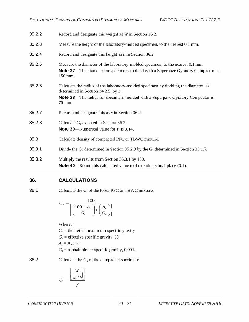
36.1 Calculate the Gr of the loose PFC or TBWC mixture:
s
s
e
s
r
G
A
G
AG
100
100
Where:
Gr = theoretical maximum specific gravity
Ge = effective specific gravity, %
As = AC, %
Gs = asphalt binder specific gravity, 0.001.
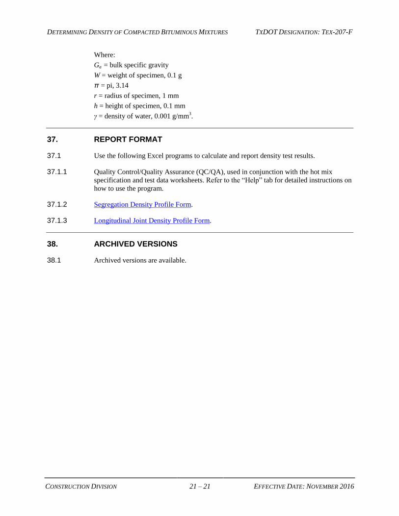
36.2 Calculate the Ga of the compacted specimen:
hr
W
Ga
2
DETERMINING DENSITY OF COMPACTED BITUMINOUS MIXTURES TXDOT DESIGNATION: TEX-207-F
CONSTRUCTION DIVISION 21 – 21 EFFECTIVE DATE: NOVEMBER 2016
Where:
Ga = bulk specific gravity
W = weight of specimen, 0.1 g
π = pi, 3.14
r = radius of specimen, 1 mm
h = height of specimen, 0.1 mm
γ = density of water, 0.001 g/mm3.
37. REPORT FORMAT
37.1 Use the following Excel programs to calculate and report density test results.
37.1.1 Quality Control/Quality Assurance (QC/QA), used in conjunction with the hot mix
specification and test data worksheets. Refer to the “Help” tab for detailed instructions on
how to use the program.
37.1.2 Segregation Density Profile Form.
37.1.3 Longitudinal Joint Density Profile Form.
38. ARCHIVED VERSIONS
38.1 Archived versions are available.
Top Related