


Languages
Pages
Legal


8/11/2019 DEsign and Fabrication of Plywood stressed skin panels
http://slidepdf.com/reader/full/design-and-fabrication-of-plywood-stressed-skin-panels 1/28
P L Y W O O D D E S I G N S P E C I F I C A T I O
A P A
T h e E n g i n e e r e d W o o d A s s o c i a t i o n
F P S E
∑ P R G
M C L E
A R R E G L B L
H Y P
x ( i )
( i ) B
P / R
R T N
R
R N B S T
H Y P
-1 S I N
-1 C O
S-1
x 2
L N
L O G
O N
f g R / S
G S B R
x y
S S T
G T O S I N
C O S x
e x
S U P P L E M E N T 3
Design And Fabrication Of
Plywood Stressed-Skin Panels
Augu st 1990

8/11/2019 DEsign and Fabrication of Plywood stressed skin panels
http://slidepdf.com/reader/full/design-and-fabrication-of-plywood-stressed-skin-panels 2/28
Wood is good. It is the earth’s natural, energy efficient and renewable
building material.
Engineered wood is a better use of wood. It uses less wood to make
more wood products.
That’s why using APA trademarked I-joists, glued laminated timbers, laminated
veneer lumber, plywood and oriented strand board is the right thing to do.
A few facts about wood. We’re not ru nning out of trees. One-third of the United States land base –
731million acres – is covered by forests. About two-thirds of that 731 million acres is
suitable for repeated planting and harvesting of timber. But only about half of the land
suitable for growing timber is open to logging. Mostof that harvestable acreage also is
open to other uses, such as camping, hiking, hunting, etc.
We’re growing more wood every day. American landowners plant more than
twobillion trees every year. In addition, millions of trees seed naturally. The forest
products industry, which comprises about 15 percent of forestland ownership, is
responsible for 41 percent of replanted forest acreage. That works out to more than one
billion trees a year, or about threemillion trees planted every day. This high rate of
replanting accounts for the fact that each year, 27percent more timber is grown
than is harvested.
Man uf act ur in g wood produ cts is
energy efficient. Wood products made
up 47percent of all industrial raw
materials manufactured in the United
States, yet consumed only 4 percent of
the energy needed to manufacture all
industrial raw materials, according
to a1987study.
Good news for a healthy planet. For every ton of wood grown, a young forest
produces 1.07tons of oxygen and absorbs 1.47 tons of carbondioxide.
Wood. It’s the right product for the environment.
Percen t o f Percen t o fMater ial Pr oduction Ener gy Use
Wood 47 4
Steel 23 48
Aluminum 2 8
D O T H E R I G H T T H I N G R I G H T ™
A P A
T h e E n g i n e e r e d W o o d A s s o c i a t i o n
NO T ICE:
The recommendatio ns in
this report apply only to
panels that bea r the APA
trademark. Only panels
bearing th e APA trademar k
are subject to the
Association’ s quali ty
auditing program. RA T E D
S H EA T H I N G
E X P O S U R E 1 S I Z E D
F O R S PA C I N
G 3 2/ 1 6 1 5/ 3 2
I N C H
0 0 0
P S 1 - 9 5
C - D P R P - 1
0 8
T HE ENGIN
EERED
W OOD AS
SOCIAT IO
NA P A
©
1 9 9 6
A P A – T H E E N G I N E E R E D W O O D A S S O C I A T I O N •
A L L R I G
H T S
R E S E R V E D . • A
N
Y
C O
P Y I N
G
, M
O
D I F I C A T I O N
, D I S T R I B U T I O
N
O
R
O
T H E R
U S E
O
F
T H I S
P U B L I C A T I O
N
O T
H E R
T H A N
A S
E X P R E S S L Y
A U T H O
R I Z E D
B Y
A P A
I S
P R O
H I B I T
E D
B Y
T H E
U . S .
C O
P Y R I G
H T
L A W
S .

8/11/2019 DEsign and Fabrication of Plywood stressed skin panels
http://slidepdf.com/reader/full/design-and-fabrication-of-plywood-stressed-skin-panels 3/28
1
This publication presents the
recommended method for the design
and fabrication of glued plywood
stressed-skin panels. Working stressesand other design criteria are given in the
PLYWOOD DESIGN SPECIFICATION,
abbreviated PDS. References are also
made to the American Forest & Paper
Association publication entitled
NATIONAL DESIGN SPECIFICATION
FOR WOOD CONSTRUCTION, and
abbreviated NDS.
The recommended design method is
based on U.S. Forest ProductsLaboratory Report No.R1220,
supplemented with tests by APA – The
Engineered Wood Association. The most
extensive of these tests are reported in
Laboratory ReportNo.82.
Presentation of this design method is
not intended to preclude further
development. Where adequate test data
are available, therefore, the design provi-
sions may be appropriately modified.
If they are modified, any such changeshould be noted when referring to
thispublication.
The plywood use recommendations
contained in this publication are based
on APA – The E ngin eered W ood
Association’s continuing program of
laboratory testing, product research and
comprehensive field experience.
However, there are wide variations in
quality of workmanship and in theconditions under which plywood is used.
Because the Association has no control
over those elements, it cannot accept
responsibility for plywood performance
or designs as actually constructed.
Technical Services Division
APA – T he En gineered Wood Associat ion
A Word on Com pon ents
Plywood-lumber components are major
structural members which depend on
the glued joints to integrate the separatepieces into an efficient unit capable of
carrying greater loads. Materials in these
components may be loaded to an
appreciably higher level than in
conventional construction.
Since improperly designed or fabricated
components could constitute a hazard
to life and property, it is strongly
recommended that components be
designed by qualified architects orengineers, using recognized design
andfabrication methods, and that
adequate quality control be maintained
during manufacture.
To be sure that such quality control has
been carefully maintained, we recom-
mend the services of an independent
testing agency. A requirement that each
unit bear the trademark of an approved
agency will assure adequate
independent inspection.
F O R E W O R D
© 1996 APA - The Engineered Wood Assoc

8/11/2019 DEsign and Fabrication of Plywood stressed skin panels
http://slidepdf.com/reader/full/design-and-fabrication-of-plywood-stressed-skin-panels 4/28
2
C O N T E N T S – D E S I G N A N D F A B R I C A T I O N O F
P L Y W O O D S T R E S S E D - S K I N P A N E L S
Foreword........................................................................................................................................................................... 1
List of Symbols.................................................................................................................................................................. 4
Part 1– Design of Plywood Stressed-Skin Panels.......................................................................................... 7
1. General...................................................................................................................................................................... 7
2. Design Considerations............................................................................................................................................... 7
2.1 Transformed Section............................................................................................................................................ 7
2.2 Design Loads............................................................................................................................................................... 7
2.3 Allowable Working Stresses......................................................................................................................................... 8
2.4 Effective Sections......................................................................................................................................................... 8
2.5 Allowable Deflection.................................................................................................................................................... 8
2.6 Camber....................................................................................................................................................................... 8
2.7 Continuous and Cantilevered Spans............................................................................................................................ 8
2.8 Connections................................................................................................................................................................ 8
3. Flexural-Panel Design......................................................................................................................................................... 9
3.1 General........................................................................................................................................................................ 9
3.2 Trial Section................................................................................................................................................................. 9
3.3 Neutral Axis and Moment of Inertia............................................................................................................................. 10
3.4 Deflection.................................................................................................................................................................... 10
3.5 Bending Moment......................................................................................................................................................... 12
3.6 Rolling Shear................................................................................................................................................................ 14
3.7 Horizontal Shear.......................................................................................................................................................... 15
3.8 Final Allowable Load................................................................................................................................................... 16
© 1996 APA - The Engineered Wood Assoc

8/11/2019 DEsign and Fabrication of Plywood stressed skin panels
http://slidepdf.com/reader/full/design-and-fabrication-of-plywood-stressed-skin-panels 5/28
3
4. Wall-Panel Design............................................................................................................................................................... 16
4.1 General........................................................................................................................................................................ 16
4.2 Vertical-Load Formula.................................................................................................................................................. 16
4.3 Combined Bending and Axial Load............................................................................................................................. 16
Part 2 – Fabrication of Plywood Stressed-Skin Panels ..................................................................................... 171. General .............................................................................................................................................................................. 17
2. Materials............................................................................................................................................................................. 17
2.1 Plywood...................................................................................................................................................................... 17
2.2 Lumber....................................................................................................................................................................... 17
2.3 Glue............................................................................................................................................................................ 17
3. Fabrication......................................................................................................................................................................... 18
3.1 Skins............................................................................................................................................................................ 18
3.2 Framing....................................................................................................................................................................... 18
3.3 Assembly..................................................................................................................................................................... 18
4. Test Samples....................................................................................................................................................................... 19
5. Identification...................................................................................................................................................................... 19
Appendix A – Approximate Design Method ..................................................................................................... 20
Appendix B – Design Example............................................................................................................................... 21
© 1996 APA - The Engineered Wood Assoc

8/11/2019 DEsign and Fabrication of Plywood stressed skin panels
http://slidepdf.com/reader/full/design-and-fabrication-of-plywood-stressed-skin-panels 6/28
4
L I S T O F S Y M B O L S A N D L O C A T I O N
A = Transformed area of a four-foot-wide panel (in.2) – 3.6.2, or a location illustrated in Figure 3.6.1
or area of stringer – Appendix B3
Ast = Actual total cross-sectional area of all stringers (in.2) – 3.4.3
At = Total cross-sectional area of all stringers and T flanges (in.2) – 3.4.4
A|| = Area of parallel plies (in.2) – 4.2
B = Width of section (in.) – 3.6.1, or a location illustrated in 3.6.1
b = Basic spacing, maximum amount of the skin which may be considered to act in conjunction with the stringer for bending
stress calculations (in.) – Table 3.2.2, Sections 3.2.2, 3.5
c = Distance from neutral axis to extreme tension or compression fiber (in.) – 3.5.5, 3.5.6, 3.6.2, Appendix A4
C = Factor for calculating allowable deflection– 3.4.4, Appendix A3
ds = Distance from centroid of stressed-skin panel to centroid of that portion of skin lying outside shear-critical plane of
skin(in.) – 3.6.2
dst = Distance from centroid of stressed-skin panel to centroid of that portion of skin lying outside shear-critical plane of
topskin(in.) – Appendix B14
dsb = Distance from centroid of stressed-skin panel to centroid of that portion of skin lying outside shear-critical plane of
bottom skin (in.) – Appendix B14
E = Modulus of elasticity (lb/in.2) – 3.5.5, 3.6.5, 4.2, Appendix A3
Etop = Modulus of elasticity of top skin (lb/in.2) – 3.4.5
EIg = Gross stiffness (lb-in.2) – 3.4.3, 3.4.4, 3.5.6, 3.6.5, 3.7.3
EIn = Stiffness of section using all material used in locating neutral axis (lb-in.2) – 3.5.3, 3.5.5
Est = Modulus of elasticity of stringers (lb/in.2) – 3.7.3
F = Allowable stress of top or bottom skin (tension or compression) adjusted in accordance with Section 3.5.4
(lb/in.2) – 3.5.5, Appendix A4
Fc = Allowable axial compressive stress for plywood skins (lb/in.2) – 4.2, 4.3
Fp = Allowable splice-plate stress multiplied by the portion of the width actually spliced (lb/in.2) – 3.5.6
Fs = Allowable rolling shear stress (lb/in.2) – 3.6.4, 3.6.5, Appendix A4
Fst = Allowable rolling shear stress in top skin (lb/in.2) – Appendix B16
Fsb = Allowable rolling shear stress in bottom skin (lb/in.2) – Appendix B16
Fv = Allowable horizontal shear stress (lb/in.2) – 3.7.3, Appendix A4
f v = Applied shear stress (lb/in.2) – 3.6.1
G = Modulus of rigidity of stringers (lb/in.2) – 3.4.3, 3.4.4
© 1996 APA - The Engineered Wood Assoc
8/11/2019 DEsign and Fabrication of Plywood stressed skin panels
http://slidepdf.com/reader/full/design-and-fabrication-of-plywood-stressed-skin-panels 7/28
5
I = Moment of inertia of one foot width of skin (in.4) – 3.4.5, 3.6.1 or moment of inertia of stringer – Appendix B3
Ig = Gross moment of inertia (in.4) – 3.3.3, 3.4.1.1, 4.2, Appendices A3, A4
In = Net moment of inertia (in.4) – 3.3.3, 3.5.1.1, Appendix A4
I|| = Effective moment of inertia of plywood parallel to direction of face grain (in.4) – Appendix B3
I⊥ = Effective moment of inertia of plywood perpendicular to direction of face grain (in.4
) – 3.4.5L = Span, length or height (ft)– 3.4.3, 3.4.4, 3.5.5, 3.7.3, 4.2, Appendix A3
l = Clear span between stringers (in.) – 3.4.5
M = Bending moment (lb-in.)– 3.5.5
P = Total load on stressed-skin panel (lb) – 3.4.3
Pa = Allowable axial load on stressed-skin panel (lb)– 4.2
Q = Statical moment of area of skin (in.3/ft of width)– 3.6.1, 3.6.2
Qs = Statical moment for rolling shear (in.3) – 3.6.3, Appendix A4
Qst = Statical moment for rolling shear– top skin (in.3) – Appendix B14
Qsb = Statical moment for rolling shear– bottom skin (in.3) – Appendix B14
Qv = Statical moment of stressed-skin panel (in.3) – 3.7.1, 3.7.3, Appendix A4
S = Section modulus of stressed-skin panel (in.3) – 4.3
t = Stringer width at stringer-to-plywood glueline (in.)– Figure 3.6.1, 3.6.4, 3.6.5, Appendix A4
V = Shear (lb) – 3.6.1
w = Load (lb/ft2) – 3.4.5
wb = Allowable load based on bending (lb/ft2) – 3.5.5, Appendix A4
wbb = Allowable load based on bending for bottom skin (lb) – Appendix B12
wbt = Allowable load based on bending for top skin (lb) – Appendix B12
wp = Allowable load based on splice-plate stress (lb/ft2) – 3.5.6, Appendix A4
ws = Allowable load based on rolling shear stress (lb/ft2) – 3.6.5, Appendix A4
wsb = Allowable load based on rolling shear stress in bottom skin (lb/ft2) – Appendix B16
wst = Allowable load based on rolling shear in top skin (lb/ft2) – Appendix B16
wv = Allowable load based on horizontal shear stress (lb/ft2) – 3.7.3, Appendix A4
w∆ = Allowable load based on deflection (lb/ft2
) – 3.4.4, Appendix A3y′ = Distance from centroid of that portion of plywood panel that lies outside of rolling-shear-critical plane to outermost
fiber(in.) – 3.6.2, Appendix B14
∆ = Deflection of top skin between stringers (in.) – 3.4.5, Appendix B8
∆s = Deflection due to shear (in.) – 3.4.3
© 1996 APA - The Engineered Wood Assoc
8/11/2019 DEsign and Fabrication of Plywood stressed skin panels
http://slidepdf.com/reader/full/design-and-fabrication-of-plywood-stressed-skin-panels 8/28
6
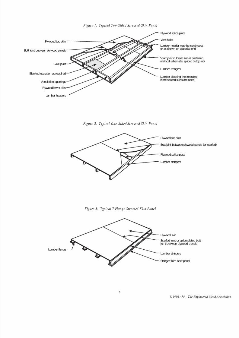
Figure 1. Typical Two-Sided Stressed-Skin Panel
Figure 2. Typical One-Sided Stressed-Skin Panel
Figure 3. Typical T-Flange Stressed-Skin Panel
Plywood splice plate
Vent holesPlywood top skin
Lumber stringers
Plywood lower skin
Lumber headers
Glue joint
Lumber header may be continuousor as shown on opposite end
Scarf joint in lower skin is preferredmethod (alternate: spliced butt joint)
Lumber blocking (not requiredif pre-spliced skins are used)
Blanket insulation as required
Ventilation openings
Butt joint between plywood panels
Butt joint between plywood panels (or scarfed)
Plywood splice plate
Plywood top skin
Lumber stringers
Scarfed joint or splice-plated butt joint between plywood panels
Plywood skin
Lumber stringers
Lumber flange
Stringer from next panel
© 1996 APA - The Engineered Wood Assoc
8/11/2019 DEsign and Fabrication of Plywood stressed skin panels
http://slidepdf.com/reader/full/design-and-fabrication-of-plywood-stressed-skin-panels 9/28
7
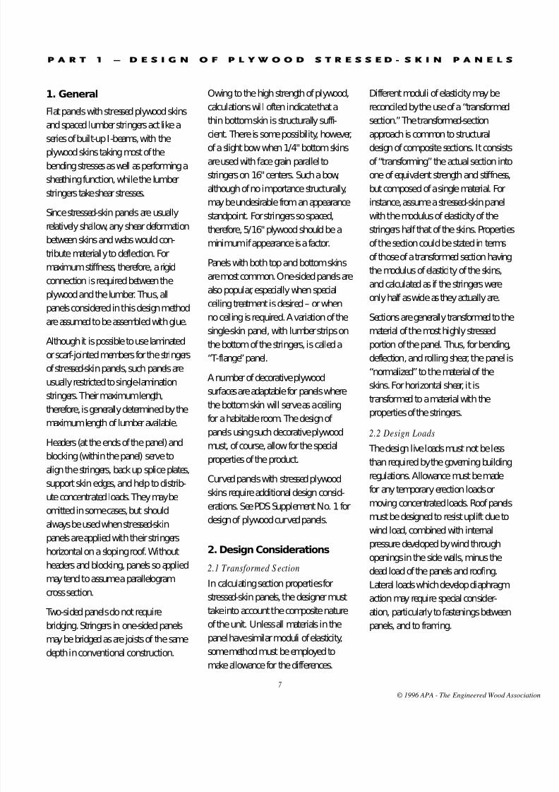
1. General
Flat panels with stressed plywood skins
and spaced lumber stringers act like a
series of built-up I-beams, with theplywood skins taking most of the
bending stresses as well as performing a
sheathing function, while the lumber
stringers take shear stresses.
Since stressed-skin panels are usually
relatively shallow, any shear deformation
between skins and webs would con-
tribute materially to deflection. For
maximum stiffness, therefore, a rigid
connection is required between the
plywood and the lumber. Thus, all
panels considered in this design method
are assumed to be assembled with glue.
Although it is possible to use laminated
or scarf-jointed members for the stringers
of stressed-skin panels, such panels are
usually restricted to single-lamination
stringers. Their maximum length,
therefore, is generally determined by the
maximum length of lumber available.
Headers (at the ends of the panel) and
blocking (within the panel) serve to
align the stringers, back up splice plates,
support skin edges, and help to distrib-
ute concentrated loads. They may be
omitted in some cases, but should
always be used when stressed-skin
panels are applied with their stringers
horizontal on a sloping roof. Withoutheaders and blocking, panels so applied
may tend to assume a parallelogram
cross section.
Two-sided panels do not require
bridging. Stringers in one-sided panels
may be bridged as are joists of the same
depth in conventional construction.
Owing to the high strength of plywood,
calculations will often indicate that a
thin bottom skin is structurally suffi-
cient. There is some possibility, however,of a slight bow when 1/4" bottom skins
are used with face grain parallel to
stringers on 16" centers. Such a bow,
although of no importance structurally,
may be undesirable from an appearance
standpoint. For stringers so spaced,
therefore, 5/16" plywood should be a
minimum if appearance is a factor.
Panels with both top and bottom skins
are most common. One-sided panels arealso popular, especially when special
ceiling treatment is desired – or when
no ceiling is required. A variation of the
single-skin panel, with lumber strips on
the bottom of the stringers, is called a
“T-flange” panel.
A number of decorative plywood
surfaces are adaptable for panels where
the bottom skin will serve as a ceiling
for a habitable room. The design of panels using such decorative plywood
must, of course, allow for the special
properties of the product.
Curved panels with stressed plywood
skins require additional design consid-
erations. See PDS Supplement No.1 for
design of plywood curved panels.
2. Design Considerations2.1 Transformed S ection
In calculating section properties for
stressed-skin panels, the designer must
take into account the composite nature
of the unit. Unless all materials in the
panel have similar moduli of elasticity,
some method must be employed to
make allowance for the differences.
Different moduli of elasticity may be
reconciled by the use of a “transformed
section.” The transformed-section
approach is common to structuraldesign of composite sections. It consists
of “transforming” the actual section into
one of equivalent strength and stiffness,
but composed of a single material. For
instance, assume a stressed-skin panel
with the modulus of elasticity of the
stringers half that of the skins. Properties
of the section could be stated in terms
of those of a transformed section having
the modulus of elasticity of the skins,
and calculated as if the stringers were
only half as wide as they actually are.
Sections are generally transformed to the
material of the most highly stressed
portion of the panel. Thus, for bending,
deflection, and rolling shear, the panel is
“normalized” to the material of the
skins. For horizontal shear, it is
transformed to a material with the
properties of the stringers.
2.2 Design Loads
The design live loads must not be less
than required by the governing building
regulations. Allowance must be made
for any temporary erection loads or
moving concentrated loads. Roof panels
must be designed to resist uplift due to
wind load, combined with internal
pressure developed by wind through
openings in the side walls, minus thedead load of the panels and roofing.
Lateral loads which develop diaphragm
action may require special consider-
ation, particularly to fastenings between
panels, andto framing.
P A R T 1 – D E S I G N O F P L Y W O O D S T R E S S E D - S K I N P A N E L S
© 1996 APA - The Engineered Wood Assoc

8/11/2019 DEsign and Fabrication of Plywood stressed skin panels
http://slidepdf.com/reader/full/design-and-fabrication-of-plywood-stressed-skin-panels 10/28
8
2.3 A llowable Working Stresses
Plywood working stresses are
determined as described in PDS
Section5.4. Lumber working stresses
are determined as described in PDS
Section 5.5. Moisture content in
serviceshould not exceed 16%.
2.4 Effective Sections
For all panels, whether containing
buttjoints or not, deflection and shear
stresses are based on the gross section of
all material having its grain parallel with
the direction of principal stress.
All plywood and all lumber having its
grain parallel to the direction of stress
may be considered effective in resisting
bending stress, except when butt-
jointed and except as reduced for
b-distance in Section3.5.
The best method for splicing skins, both
from the structural and appearance stand-
point, is to scarf-joint the plywood to the
desired length. PDS Section5.6 gives
strength factors for various slopes of scarf.
Another method, considerably simplerthan scarfing, involves the use of
plywood splice plates. Allowable
stressesfor these end joints are also
given in PDS Section5.6. Splice plates
are used only between the stringers, and
consequently there is a certain
percentage of the panel which is not
spliced. When calculating the strength
of the panel at the splices, only the
portion of the skin which is actuallyspliced should be considered effective.
If desired, lengths of splice plates in skins
may be reduced from those listed in the
PDS. The strength of the joint will be
reduced in proportion. Width and
thickness of plates should not be reduced.
2.5 Allowable Deflection
Deflection must not exceed that allowed
by the applicable building code. Maxi-
mum deflections recommended by
most codes are the following
proportions of the spanl in inches:
Floor Panels
Live load only l/360
Dead plus live load l/240
Roof Panels
Live load only l/240
Dead plus live load l/180
More severe limitations may be required
by special conditions.*
2.6 Camber Camber may be provided opposite to
the direction of anticipated deflection
for purposes of appearance or utility.
Itwill have no effect on strength or
actual stiffness.
Where roof and floor panels are
cambered, a recommended minimum
amount is 1.5times the deflection due
to dead load only. This will provide a
nearly level panel under conditions of
no live load after set has occurred.
Additional camber may be introduced as
desired to provide for drainage or
appearance. Roof panels must be
designed to prevent ponding of water.
Ponding may be prevented either by
cambering or by providing slope or
stiffness such that it will not occur.*
2.7 Continuous and
Cantilevered Spans
Stressed-skin panels may be cantilevered
and/or continuous over interior sup-
ports. Stresses can be figured by normal
engineering formulas for multiple-span
application or for cantilever action.
Negative moments, of course, require
that the top skin be adequately spliced
for tension, and the bottom skin thick
enough to perform with the lower
allowable compressive stresses.
2.8 Connections2.8.1 General
Connections of panels to supporting
members must resist uplift as well as
downward loads. Connections between
stressed-skin panels must transfer
concentrated loads between sections
without excessive differential deflection.
Connections should also be detailed to
restrain slight bowing which sometimes
results from moisture changes.
To avoid bowing, which can be caused
by slight expansion of panels, it is advis-
able not to drive them tightly together. A
suitable allowance is about 1/16" at the
side of 4-ft-wide panels, and perhaps
1/4" at the ends of 20-ft-long panels.
2.8.2 Diaphragms
A roof, wall or floor designed as a shear
diaphragm may require more fasteningthan would ordinarily be needed simply
to attach the panels. Such additional
fastening may be designed in accor-
dance with the APA publication entitled
D esign /C onstru ction Guide – D iaphra gm s,
Form No. L350, and with accepted
engineering practice.
The glueline between the stringers and
plywood skins must transfer shear due to
loads in the plane of the panel, as well asshear due to loads perpendicular to the
stressed-skin panels. These shear stresses
*For further discussion, see section on camber inAmerican Institute of Timber Construction Timber
Construction Manual, and AITC Technical Note No. 5
Roo f S lope a nd D rain age for Flat or N early F lat Roofs.
© 1996 APA - The Engineered Wood Assoc

8/11/2019 DEsign and Fabrication of Plywood stressed skin panels
http://slidepdf.com/reader/full/design-and-fabrication-of-plywood-stressed-skin-panels 11/28
9
will be additive and the resultant stress
should be checked against the allowable
rolling shear stress of plywood, appro-
priately adjusted for duration of load.
When analyzing the shear stress,
appropriate load combinations should be
selected, since the diaphragm load will
generally not occur at the same time as
full vertical dead load and live load.
The allowable diaphragm load may be
limited by the glueline stresses, particu-
larly if one-sided or T-flange stressed-
skin panels are used.
3. Flexural Panel Design
3.1 General
Due to the structural efficiency possible
with stressed-skin panels, whereby rela-
tively shallow panels prove adequate for
strength, the design is likely to be con-
trolled by the allowable deflection. The
first aspect of the assumed section to be
checked, therefore, will be deflection.
Moment will be checked next, and shear
last– since it is least likely to control.
Shear will, however, sometimes governwhen one or both skins are thick and
the span is short.
3.2 Trial Section
3.2.1 General
Stressed-skin panels are designed by a
“cut and try” method. A trial section
must first be assumed and then checked
for its ability to do the job intended. The
whole 4-ft-wide panel is usually designed
as a unit, in order to allow for edge con-
ditions. (The equations in the following
sections are based on 4-ft-wide panels.
They will require adjustment for any
other panel width.)
3.2.2 “b Distan ce”
In some cases the whole 4-ft width of
the skins cannot be considered effective,
since there is a tendency for thin
plywood to dish toward the neutral
axisof the panel when stringers are
widely spaced. A Basic Spacing, usually
referred to as the “b distance”, is used
totake this tendency into account.
Theb distance represents the maximum
amount of the skin which may be
considered to act in conjunction with
the stringer for bending stress calcula-
tions. A table ofb distances is given
below. Panels in which the clear distance
between longitudinal members exceeds
2b for both covers should not beconsidered as having stressed skins.
3.2.3 On e-Sided Panels
3.2.3.1 Panels Over 3" Deep–
One-sided stressed-skin panels,
exceptthe shallow ones covered in
Section3.2.3.2 below, are designed just
as are two-sided panels. There is, of
course, no bottom skin to be taken into
account in calculating moment of inertia,
and the resisting moment based on the
bottom of the panel uses the allowable
bending-stress value for the stringers.
A variation on the one-sided panel is
sometimes called a “T-flange” panel,
and is illustrated below. The lumber
“web” and lumber “bottom flange” may
be considered integral for design pur-
poses when they are glued together.
When determining load governed by a
1x4 or 2x4 T-flange, use the allowable
bending stress of the flange lumber. The
allowable tensile stress of the flange
lumber should be used for lx6 and 2x6
T-flanges. The designer should use engi-
neering judgment when selecting the
allowable stress for other size T-flanges.
Table 3.2.2 Basic Spacing, b , For Various Plyw ood T hicknesses
Basic Spacing,b (inches)*
Plywood Face Grain || to Stringers Face Grain⊥ to Stringers
Thickness 3, 4, 5-ply 5, 6-ply 3, 4, 5-ply 5, 6-ply(in.) 3-layer 5-layer 3-layer 5-layer
Unsanded Panels5/16 12 – 13 –3/8 14 – 17 –
15/32, 1/2 18 22 21 2719/32, 5/8 23 28 22 3123/32, 3/4 31 32 29 31
Sanded Panels1/4 9 – 10 –
11/32 12 – 13 –3/8 19 – 15 –
15/32 19 22 18 24
1/2 20 24 19 2619/32 – 27 – 285/8 – 28 – 30
23/32 – 33 – 343/4 – 35 – 36
Touch-Sanded Panels1/2 19 24 21 27
19/32, 5/8 26 28 24 2923/32, 3/4 32 34 28 36
1-1/8 (2-4-1) – 55 – 55
*Use value in boldface for plywood thickness and orientation unless another layup is specified and available.
© 1996 APA - The Engineered Wood Assoc

8/11/2019 DEsign and Fabrication of Plywood stressed skin panels
http://slidepdf.com/reader/full/design-and-fabrication-of-plywood-stressed-skin-panels 12/28
10
3.2.3.2 Panels Less Than 3" Deep– In
one-sided stressed-skin panels less than
3" deep, the tendency for the skins to
dish is more serious than in other
panels. This factor should be taken into
account in their design. When designing
such shallow sections, a value of 0.5b
should be used in place of the full b
value given in the table. (See Sections
3.4.1.2 and3.5.1.2.)
3.3 Neutral Axis and Moment
of Inertia
3.3.1 A llowance for Surfacing
To allow for resurfacing of lumber
members for gluing, they should be
considered 1/16" smaller in dimensionperpendicular to each gluing surface
than their standard lumber size.
Stringers for two-sided panels, which
have two gluing surfaces, should then
be considered 1/8" smaller than their
standard lumber size.
3.3.2 Transformed S ection
Since stiffness of plywood skins may be
different from that of lumber stringers, it
is necessary to calculate on the basis of a
“transformed section.” A transformed
section is a section equivalent in
strength and stiffness to the actual one,
but “transformed” to the properties of
one material. Use of such a device
simplifies calculation.
Where a portion of a section is to be
transformed to another material, its
actual area must be multiplied by the
ratio of its actual stiffness to that of the
other material, thus arriving at an
“effective” area of the new material.
3.3.3 Gross and Net Sections
It will sometimes be necessary to
compute one moment of inertia fordeflection and shear, and another for
bending stress, since the two consider-
ations are based on different aspects of
panel behavior. Allowable bending
stresses are determined by applying
suitable reduction factors to the stresses
obtained at ultimate; allowable deflec-
tions are arbitrarily set, and applied, of
course, to the behavior of the panel in
its working range. “Dishing” of the skinsat high load has been mentioned in
Section 3.2.2. Because of it, a smaller
net section may be effective at ultimate
loads than in the working range. For
thin skins and wide stringer spacings,
therefore, this net moment of inertia
forbending, In, may be less than the
gross moment of inertia for deflection
and shear, Ig.
3.3.4 Calculation Method
The usual system for figuring neutral
axis and moment of inertia involves
taking moments about the plane of the
bottom of the panel. Use the actual
resurfaced cross-sectional area of the
lumber members, modified as appro-
priate by transformed section, also
considering applicableb distances.
3.4 Deflection
3.4.1 Cross Section
3.4.1.1 Other Than Shallow One-
Sided Sections– The full 4-ft width of
plywood is used for neutral-axis and
moment-of-inertia calculations for deflec-
tion of most panels. This includes panels
like the one sketched below, which does
not have a stringer at each edge. The
resultant moment of inertia is called the
“gross moment of inertia,” or Ig.
3.4.1.2 Shallow One-Sided Sections–
As mentioned in Section 3.2.3.2, for
one-sided sections less than 3" deep, the
gross width may be used in computing
the moment of inertia only when theclear distance between stringers is less
thanb (from Table 3.2.2). When the
clear distance is greater thanb, the
flange width for stiffness calculations
must be taken as the sum of the stringer
width plus a distance equal to 0.25b on
each side of each stringer (except, of
course, for exterior stringers where only
part of that distance is available).*
3.4.2 N eutral Ax is for Deflection
Different moduli of elasticity must be
reconciled by use of a transformed
section in computing both the neutral
axis and the moment of inertia. In the
neutral-axis calculation, one way of
allowing for differences in moduli is to
multiply each A|| by its appropriate E.
(See Appendix B, Section B5.)
3.4.3 Stiffness
The EI, using the neutral axis computed
in 3.4.2, will be a stiffness factor for
bending deflection alone. It will not
include shear deflection.
Figure 3.2.3 “T-Flange” Panels
Plywood Top Skin
Lumber Flange
Lumber Stringer (web)
*This jump, from gross width where spacing
between stringers isb, to slightly over half the gross
width where spacing is greater thanb, is inaccordance with test results. See Laboratory Report
No. 82, STRESSED-SKIN PANEL TESTS, Figure13.
© 1996 APA - The Engineered Wood Assoc

8/11/2019 DEsign and Fabrication of Plywood stressed skin panels
http://slidepdf.com/reader/full/design-and-fabrication-of-plywood-stressed-skin-panels 13/28
In dealing with overall stiffness of the
panel, use gross stiffness (EIg). It reflects
the composite nature of the panel. In
later calculations, values for effective
moment of inertia will be required. They
can be obtained by dividing the EI by
the appropriate E for the part of the
panel being considered. (See Appen-
dixA for simplified equations when
moduli of elasticity of skins and
stringersare essentially equal, and
maybe considered to cancel.)
Shear deflection should be considered
separately for stressed-skin panels,
whereas for most timber design it is
“automatically” taken into account in
the modulus of elasticity. The moduli
listed for timber materials are not
actually moduli for pure bending.
Listedvalues for plywood include a
10%allowance, and lumber values
include a 3% allowance for shear
deflection. These factors are good
approximations for most applications,
but are excessive for most stressed-skin
panels. (See Appendix A for short form,
“Approximate” design method which
uses listed values.)
Bending deflection must be calculated
using a true value for bending modulus
of elasticity. This true value is obtained
by restoring the amounts mentionedabove as having been removed from the
modulus of elasticity to approximate
shear deflection. A value for shear
deflection, computed separately, is then
added to the first figure representing the
moment deflection. The simple-span
shear deflection for uniform (also
quarter-point) loading is given by
thefollowing equation:
∆s = 1.8 PL _____ AstG
where
∆s= shear deflection (in.)
P= total load on panel (lb)
L= span length (ft)
Ast= actual total cross-sectional area of
all stringers (in.2)
G= modulus of rigidity of stringers
(psi). G may be taken as 0.06 of
the true bending modulus of
elasticity of stringers.
This equation gives the shear deflection
for uniform loading or quarter-point
loading. The shear deflection for a single
concentrated load at the center is double
this amount; the shear deflection of a
cantilever with a uniformly distributed
load is four times this amount.
3.4.4 A llowable Load
Combining equations for bending and
shear deflections for a uniformly loaded
simple-span panel, the allowable load
based on deflection is then given by
thefollowing:*
w∆=1 __________________
CL [7.5L2+
0.6 ] ____ ___ EIg AtG
where
w∆= allowable load based on
deflection (psf)C= factor for allowable deflection,
usually 360 for floors,
240 for roofs*
L= span length (ft)
EIg= stiffness factor from Section 3.4.3
for a 4-ft-wide panel (lb-in.2)
At= actual total cross-sectional area of
all stringers, and T-flanges if
applicable (in.2)
G= modulus of rigidity of stringers
(psi). G may be taken as 0.06 of
the true bending modulus of
elasticity of stringers.
Figure 3.4.1.1 Total Panel W idth Effective(without reference to b distance)
Figure 3.4.1.2 Effective Width is Sum of Widths S hown Sha ded
b⁄4 b⁄4
b⁄4b⁄4 b⁄4
b⁄4
b⁄4
Eff.
Eff.Eff.
Eff.
Eff.
1 1
*Note that if the allowable-deflection factor, C, is
based on live load only, this equation will yieldallowable live load, to which dead load may be added.
© 1996 APA - The Engineered Wood Assoc

8/11/2019 DEsign and Fabrication of Plywood stressed skin panels
http://slidepdf.com/reader/full/design-and-fabrication-of-plywood-stressed-skin-panels 14/28
1 2
The constants shown in the above
equation result from collecting constants
for the simple-span beam equations,
appropriately adjusted for panel width
and conversion of units. For instance,
7.5= 5 x 4 x 1 x 1728 ___ __ 384 12
3.4.5 Top-Skin Deflection
In addition to computing the deflection
of the whole panel acting as a unit, the
designer must also check the deflection
of the top skin between stringers.
Sections are usually selected such that
deflection only must be checked for this
top skin, but for unusual applications
moment and shear should also beinvestigated. For two-sided panels, this
skin will be a fixed-end “beam” for
which the equation is:
∆ =4wl 4 __________
384 EtopI 12
where
A = deflection (in.)
w = load (psf)
l = clear span between stringers (in.)
Etop= modulus of elasticity for top
skin(psi)
I = moment of inertia (in direction
perpendicular to stringers) of
1-ft width of top skin (in.4).
For one-sided panels with four stringers,
the skin will act like a 3-span beam,
with the following equation:
∆ =4wl 4 ________
581 EI 12
where all symbols are as above. (For the
refined method which includes shear
deflection of the plywood, see PDS
Section 3.1.3.)
In most stressed-skin panels, the face
grain will be parallel to supports and it
will therefore be necessary to use in
these equations the correct I value for
the perpendicular direction. This value
for I⊥ can be taken from the PDS.
3.5 Bending Moment
3.5.1 Cross Section
3.5.1.1 Other Than Shallow One-
Sided Sections – As mentioned in
Section 3.3.3, for bending considerations
only it is sometimes necessary to calcu-
late using the reduced section provided
by using theb distance to arrive at
effective skin widths. If the clear distance
between stringers is less thanb, theeffective width of skin is equal to the full
panel width. Neutral axis and moment
of inertia are then as figured above for
deflection. If the clear distance is greater
thanb, the effective width of skins must
be reduced. It equals the sum of the
widths of the stringers plus a portion of
the skin extending a distance equal to
0.5b each side of each stringer (except,
of course, for outside stringers where
only part of that distance is available).
The resultant moment of inertia is called
the “net moment of inertia,” or In.
3.5.1.2 Shallow One-Sided Sections –
The neutral axis and moment of inertiaused for shallow one-sided panels are
the same as those used above for deflec-
tion; that is, using 0.25b instead of 0.5b
when stringer spacing is greater thanb
(Figure 3.4.1.2).
3.5.2 N eutral Axis for Moment
A new neutral axis for bending should
be computed using the proper section
determined in the paragraph above.
Only those plies whose grain is parallelto the span are used. As for deflection,
the different stiffnesses of the materials
must be considered.
3.5.3 Moment of Inertia
The EIn of the section for bending is
computed considering the material
usedin locating the neutral axis.
l ∆
Figure 3.4.5 Top-Skin Deflection
Figure 3.5.1
Effective Width of Top Skin
(Often Equals Full Panel Width)
Effective Width of Bottom Skin
(Usually Reduced for b Distance)
N.A.
b ⁄2 b ⁄2b ⁄2 b ⁄2
Eff. Eff. Eff.
© 1996 APA - The Engineered Wood Assoc

8/11/2019 DEsign and Fabrication of Plywood stressed skin panels
http://slidepdf.com/reader/full/design-and-fabrication-of-plywood-stressed-skin-panels 15/28
1 3
3.5.4 Allowable St resses
As the spacing between framing
members is increased, the allowable
load is reduced in two ways. The first
has been accounted for in considering
theb distance. The second involves
reductions in allowable stresses. The
allowable stresses, both in tension and
compression, for the grade of plywood
used, are reduced in accordance with
Figure 3.5.4.
This reduction is to provide against
buckling of the skins. It applies to
working stresses in both tension and
compression parallel to grain, but not
torolling-shear stresses.3.5.5 Allowable Load
Most stressed-skin panels with spaced
stringers are not symmetrical about the
neutral axis. For such “unbalanced
sections,” it will be necessary to calcu-
late the allowable load in bending as
determined both by the top skin and
bythe bottom. The lower of these
values will then govern, unless there is
asplice in an area of high moment. (If there is, an additional check on the
splice will be required.)
For uniform loads, the general equation
M =FI __ c
reduces to the following:
wb =8F (EIn) _______ 48 cL2E
where
wb= allowable load based on bending
(psf)
F= allowable stress (either tension or
compression adjusted in accor-
dance with Sec. 3.5.4) (psi)
EIn= stiffness factor computed in
Section 3.5.3 for bending (lb-in.2)
c= distance from neutral axis to
extreme tension or compression
fiber (in.)
L= span (ft)E= appropriate modulus of elasticity
for the skin being considered (psi).
3.5.6 Splice-Plate Design
Resisting moment of the splice must be
computed using the allowable stresses
from PLYWOOD DESIGN SPECIFICA-
TION Section5.6. In the case of splice
plates, this allowable stress is applied
over only the width of skin actually cov-
ered by splice plates. The gross I is used
for calculating this splice-plate resisting
moment, since full width of skins is
effective at this point, due to the stiffen-
ing effect of splice plate and blocking.
The following equation is valid for a splice
plate at the point of maximum moment.
wp =8Fp (EIg) _______ 48 cL2E
where
wp= allowable load based on splice-
place stress (psf)
Fp= allowable splice-plate stress
multiplied by the proportion of
the width actually spliced (psi)
EIg= Stiffness factor computed in
Section 3.4.3 for deflection (lb-in.2)
and other symbols are as above.
If the splice is in an area of high
moment, and is found to control the
design, often the best thing to do is to
change the location of the splice to an
area of lower stress.
Figure 3.5.4Stress Reduction Factor for Framing M ember Spa cing
P e r c e n t a g e o f A l l o w a b l e S t r e s s
Ratio of Clear Distance Between Longitudinal Members to Basic Spacing, b
(66.7%)
0 0.5 1.0 1.5 2.0
100%
90%
80%
70%
60%
© 1996 APA - The Engineered Wood Assoc

8/11/2019 DEsign and Fabrication of Plywood stressed skin panels
http://slidepdf.com/reader/full/design-and-fabrication-of-plywood-stressed-skin-panels 16/28
1 4
3.6 Rolling Shear
3.6.1 L ocation of Critical Stress
When the plywood skin has its face grain
parallel to the longitudinal framing
members, as is usually the case, the criti-
cal shear plane lies within the plywood.
It is between the inner face ply and the
adjacent perpendicular ply (at A or B).
When the face grain of the skin is
perpendicular to the framing members,
the critical rolling-shear plane lies
between the inner face and the framing
member (at A' or B').
The standard equation for shear is
f v =
VQ. ___
IB
An “unbalanced” stressed-skin panel
has two values for Q – one for the
thicker skin, and one for the thinner.
Since the Q of the thicker skin is almost
always larger than that of the thinner
skin, it is generally sufficient to compute
rolling shear only for the thicker skin.
3.6.2 Transformed S ection
In calculating Q, as in calculating neutralaxis and moment of inertia, it is necessary
to use a “transformed section.” The
approach used here, however, is typically
different. The Q calculated is for that area
outside the shear-critical plane, not the Q
for the entire skin. Since skins are typi-
cally applied with face grain parallel to
the stringers, the skin’s shear-critical
plane is at the first glueline away from the
stringer. In a 5-ply skin, for instance, theQ is calculated for the outer four plies.
Table 3.6.2 eliminates the complication
which is involved in calculating the Q
for this transformed section. With this
table, the designer can calculate the Q
of the plies outside the critical plane by
simply multiplying the two numbers.
One of these numbers is given directly
in the table. It represents the “trans-
formed” area of the required plies, A,
fora 4-ft-wide panel.
The distance (ds) by which this area
must be multiplied is not presented
directly, but is easy to obtain. It is the
distance from the centroid of the trans-
formed area to the neutral axis of the
stressed-skin panel. Note that the neutral
axis is as determined for deflection, in
Section 3.4.2. To obtain ds, subtract from
the total distance between N.A. and
outside of panel, c, the distance between
outside of panel and centroid of
transformed area outside the critical plane
for rolling shear, y'. In equation form,
ds = c – y'
3.6.3 Statical Moment
The Qs, or statical moment for rolling
shear, is then given by the following
equation:
Qs = A ds
3.6.4 A llowable Capacity
It is convenient to compute a value for
the sum of the allowable shear stress
times the applicable shear width, ΣFst,
over all joints. Note that due to stress
concentrations, the allowable stress in
rolling shear for exterior stringers is only
half that for interior stringers.
This reduction applies to exterior
stringers whose clear distance to the
panel edge is less than half the clear
distance between stringers.
3.6.5 A llowable Load
The allowable uniform load on a simple-
span stressed-skin panel as determined
by rolling shear can be expressed by the
following equation:
ws =2(EIg)ΣFst _________
4QsLE
where
ws= allowable load based on rolling
shear stress (psf)
EIg= stiffness factor, computed in
Section 3.4.3 (lb-in.2)
Figure 3.6.1 Location of Critical Rolling S hear Stress
t t
t t
B'
B
B
B'
A'
A
A
A'
© 1996 APA - The Engineered Wood Assoc
8/11/2019 DEsign and Fabrication of Plywood stressed skin panels
http://slidepdf.com/reader/full/design-and-fabrication-of-plywood-stressed-skin-panels 17/28
1 5
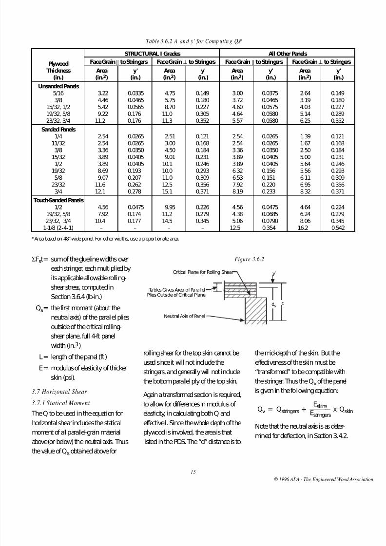
Table 3.6.2 A an d y' for Comp utin g Qs*
STRUCTURAL I Grades All Other Panels
Plywood Face Grain || to Stringers Face Grain⊥ to Stringers Face Grain || to Stringers Face Grain⊥ to Stringers
Thickness Area y' Area y' Area y' Area y'(in.) (in.2) (in.) (in.2) (in.) (in.2) (in.) (in.2) (in.)
Unsanded Panels
5/16 3.22 0.0335 4.75 0.149 3.00 0.0375 2.64 0.1493/8 4.46 0.0465 5.75 0.180 3.72 0.0465 3.19 0.18015/32, 1/2 5.42 0.0565 8.70 0.227 4.60 0.0575 4.03 0.22719/32, 5/8 9.22 0.176 11.0 0.305 4.64 0.0580 5.14 0.28923/32, 3/4 11.2 0.176 11.3 0.352 5.57 0.0580 6.25 0.352
Sanded Panels1/4 2.54 0.0265 2.51 0.121 2.54 0.0265 1.39 0.121
11/32 2.54 0.0265 3.00 0.168 2.54 0.0265 1.67 0.1683/8 3.36 0.0350 4.50 0.184 3.36 0.0350 2.50 0.184
15/32 3.89 0.0405 9.01 0.231 3.89 0.0405 5.00 0.2311/2 3.89 0.0405 10.1 0.246 3.89 0.0405 5.64 0.246
19/32 8.69 0.193 10.0 0.293 6.32 0.156 5.56 0.2935/8 9.07 0.207 11.0 0.309 6.53 0.151 6.11 0.309
23/32 11.6 0.262 12.5 0.356 7.92 0.220 6.95 0.356
3/4 12.1 0.278 15.1 0.371 8.19 0.233 8.32 0.371Touch-Sanded PaneIs
1/2 4.56 0.0475 9.95 0.226 4.56 0.0475 4.64 0.22419/32, 5/8 7.92 0.174 11.2 0.279 4.38 0.0685 6.24 0.27923/32, 3/4 10.4 0.177 14.5 0.345 5.06 0.0790 8.06 0.345
1-1/8 (2•4•1) – – – – 12.5 0.354 16.2 0.542
*Area based on 48"-wide panel. For other widths, use a proportionate area.
Figure 3.6.2
Tables Gives Area of ParallelPlies Outside of Critical Plane
Critical Plane for Rolling Shear
Neutral Axis of Panel
y′
dsc
ΣFst= sum of the glueline widths over
each stringer, each multiplied by
its applicable allowable rolling-
shear stress, computed inSection 3.6.4 (lb-in.)
Qs= the first moment (about the
neutral axis) of the parallel plies
outside of the critical rolling-
shear plane, full 4-ft panel
width(in.3)
L= length of the panel (ft)
E= modulus of elasticity of thicker
skin (psi).
3.7 Horizontal Shear
3.7.1 Statical Moment
The Q to be used in the equation for
horizontal shear includes the statical
moment of all parallel-grain material
above (or below) the neutral axis. Thus
the value of Qsobtained above for
rolling shear for the top skin cannot be
used since it will not include the
stringers, and generally will not include
the bottom parallel ply of the top skin.
Again a transformed section is required,
to allow for differences in modulus of
elasticity, in calculating both Q and
effective I. Since the whole depth of the
plywood is involved, the area is that
listed in the PDS. The “d” distance is to
the mid-depth of the skin. But the
effectiveness of the skin must be
“transformed” to be compatible with
thestringer. Thus the Qvof the panelisgiven in the following equation:
Qv = Qstringers +Eskins
x Qskin ________
Estringers
Note that the neutral axis is as deter-
mined for deflection, in Section 3.4.2.
© 1996 APA - The Engineered Wood Assoc

8/11/2019 DEsign and Fabrication of Plywood stressed skin panels
http://slidepdf.com/reader/full/design-and-fabrication-of-plywood-stressed-skin-panels 18/28
1 6
4. Wall Panel Design
4.1 General
Stressed-skin panels used for walls, or
other applications where they are loaded
in axial compression, can be designed in
accordance with standard procedures.In practice, when these panels are used
for walls, their thickness is usually deter-
mined by appearance, acoustics, or
insulation requirements, and sometimes
by the necessity for wind resistance, but
seldom by their actual load-bearing
capacity as columns.
4.2 Vertical-Load Formula
Few practical end joints for stressed-skin
panels will provide any appreciabledegree of fixity. Under vertical load,
therefore, panels will behave as pin-
ended columns. The pin-ended-column
equations reduce to:
Pa =3.619 EIg
or FcA|| ________
144 L2
whichever is less
where
Pa = allowable axial load on the
panel (lb)
E = appropriate modulus of elasticity
(see below) (psi)
Ig = gross moment of inertia of panel
about neutral axis (in.4)
L = unsupported vertical height of
panel (ft)
Fc = allowable compressive stress
(axial) for plywood skins (psi)
A|| = total vertical-grain material of
stringers and skins (in.2).
Where the moduli of elasticity of skins
and stringers are nearly alike, the modu-
lus of elasticity of the skins may be used.
Otherwise, calculate EIgas in Section3.4.3 for use in this equation.
4.3 Com bined Bending and Axial Load
When designing wall panels subject to
wind loads, or any other panels where
bending and axial stresses are both pre-
sent, the usual combined-load equation,
P/A±
M/S 1, reduces to the
___ ____ Fa Fb
following:
P+
M/S 1.0
__ ____ Pa Fc
where
P= total allowable axial load on the
panel with combined loading (lb)
Pa= allowable axial load on the panel
(from Section 4.2) if axial load only
existed (lb)
M= total allowable bending moment
on the stressed-skin panel withcombined loading (in.-lb)
S= section modulus of stressed-skin
panel (compression side) =
In/c(in.3)
Fc= allowable stress in compression
parallel to grain from PDS Table 3
(psi).
Values for Paand Fccan be adjusted for
duration of load. See PDS Section 3.3.
3.7.2 A llowable Shear Stress
Allowable horizontal shear stresses for
stress-grade lumber are given in the
NATIONAL DESIGN SPECIFICATION
FOR WOOD CONSTRUCTION (NDS).
3.7.3 Allowable Load The equation for allowable uniform load
on a stressed-skin panel is as follows:
wv =2(EIg)ΣFvt _________
4QvLEst
where
wv= allowable load based on
horizontal shear stress (psf)
EIg= Stiffness factor, computed in
Section 3.4.3 (lb-in.2)
Fv= allowable horizontal shear stress
in the lumber stringers (psi)
t= stringer width (in.)
Qv= first moment about the neutral
axis of all parallel-grain material
above (or below) the neutral axis
of the 4-ft-wide panel (in.3)
L = length of the panel (ft)
Est = modulus of elasticity of stringers(psi).
3.8 Final A llowable Load
The final allowable load on the panel is
the lowest of the figures obtained in
Section 3.4 through 3.7 above.
© 1996 APA - The Engineered Wood Assoc
8/11/2019 DEsign and Fabrication of Plywood stressed skin panels
http://slidepdf.com/reader/full/design-and-fabrication-of-plywood-stressed-skin-panels 19/28
1 7
1. General
1.1
This specification covers the fabrication
of glued plywood stressed-skin panels,with spaced stringers of lumber or
plywood, and with skins of plywood
glued to one or both sides.
1.2
Plywood stressed-skin panels should be
designed by a qualified architect or
engineer in accordance with the latest
edition of the APAPLYWOOD DESIGN
SPECIFICATION (PDS), using the
method set forth in Part1 of this PDS
Supplement. Other design methods
may be employed, provided they are
supported by adequate test data.
1.3
Plywood stressed-skin panels shall be
fabricated and assembled in accordance
with engineering drawings and speci-
fications, except that minimum
requirements herein shall be observed.
1.4
The plywood use recommendations
contained in this publication are based
on APA’scontinuing program of
laboratory testing, product research and
comprehensive field experience. How-
ever, there are wide variations in quality
of workmanship and in the conditions
under which plywood is used. Because
the Association has no control over
those elements, it cannot accept
responsibility for plywood performance
or designs as actually constructed.
2. Materials
2.1 Plywood
2.1.1
Plywood shall conform with the latest
edition of U.S. Product Standard PS-1 for
Construction and Industrial Plywood.
Each original panel shall bear the trade-
mark of APA – Th e En gineered Wood
Association . Any precut plywood shall be
accompanied by an affidavit from the pre-
cutter certifying that each original panel
was of the specified type and grade, and
carried thetrademark of APA – The
Engineered W ood A ssociation.
2.1.2
At time of gluing, the plywood shall be
conditioned to a moisture content
between 7% and 16%. Pieces to beassembled into a single stressed-skin
panel shall be selected for moisture
content to conform with Section 3.3.1.
2.1.3
Surfaces of plywood to be glued shall be
clean and free from oil, dust, paper tape,
and other material which would be detri-
mental to satisfactory gluing. Medium
density overlaid surfaces shall not be
relied on for a structural glue bond.
2.2 Lumber
2.2.1
Grades shall be in accordance with
current lumber grading rules, except thatknotholes up to the same size as the
sound and tight knots specified for the
grade by the grading rules may be per-
mitted. When lumber is resawn, it shall
be regraded on the basis of the new size.
2.2.2
At time of gluing, the lumber shall be
conditioned to a moisture content
between 7% and 16%. Pieces to be
assembled into a single stressed-skin
panel shall be selected for moisture
content to conform with Section 3.3.1.
2.2.3
Surfaces of lumber to be glued shall be
clean and free from oil, dust, and other
foreign matter which would be detri-
mental to satisfactory gluing. Each piece
of lumber shall be machine finished, but
not sanded, to a smooth surface with amaximum allowable variation of 1/32" in
the surface to be glued. Warp, twist, cup
or other characteristics which would
prevent intimate contact of mating glued
surfaces shall not be permitted.
2.3 Glue
2.3.1
Glue shall be of the type specified by
designer for anticipated exposure
conditions.
P A R T 2 – F A B R I C A T I O N O F P L Y W O O D
S T R E S S E D - S K I N P A N E L S
© 1996 APA - The Engineered Wood Assoc

8/11/2019 DEsign and Fabrication of Plywood stressed skin panels
http://slidepdf.com/reader/full/design-and-fabrication-of-plywood-stressed-skin-panels 20/28
1 8
2.3.2
Interior type glue shall conform with
ASTM Specification D4689. Exterior
type glue shall conform with ASTM
Specification D2559.
2.3.3Mixing, spreading, storage-, pot-, and
working-life, and assembly time and
temperature shall be in accordance with
the manufacturers’ recommendations.
3. Fabrication
3.1 Skins
3.1.1
Slope of scarf and finger joints inplywood skins shall not be steeper than
1 in 8 in the tension skin, and 1 in 5 in
the compression skin. Scarf and finger
joints shall be glued under pressure over
their full contact area, and shall meet
the requirements of PS1, Section 3.9.
Inaddition, the aggregate width of all
knots and knotholes falling wholly
within the critical section shall be not
more than 10" on each face of the
jointed panel for a 4-ft-wide panel, and
proportionately for other widths. The
critical section for a scarf joint shall be
defined as a 12"-wide strip, 6" on each
side of the joint in the panel face,
extending across the width of the panel.
3.1.2
Butt joints in plywood skins shall be
backed with plywood splice plates cen-
tered over the joint and glued over their
full contact area. Splice plates shall be at
least equal in thickness to the skin,
except that minimum thickness shall be
15/32" if nail-glued. Minimum splice
plate lengths, face grain parallel with that
of the skin, shall be as follows (unless
otherwise called for in the design):
Skin Thickness Splice Plate Length
1/4" 6"
5/16" 8"
3/8" sanded 10"
3/8" unsanded 12"
15/32" & 1/2" 14"
19/32" - 3/4" 16"
3.1.3
Surfaces of high density overlaidplywood to be glued shall be roughened,
as by a light sanding, before gluing.
3.2 Framin g
3.2.1
Scarf and finger joints may be used in
stringers, provided the joints are as
required for the grade and stress used in
the design. Knots or knotholes in the
end joints shall be limited to thosepermitted by the lumber grade, but in
any case shall not exceed 1/4 the
nominal width of the piece.
3.2.2
The edges of the framing members to
which the plywood skins are to be glued
shall be surfaced prior to assembly to
provide a maximum variation in depth
of 1/1 6" for all members in a panel.
(Allow for actual thickness of any spliceplates superimposed on blocking.)
3.3 Assembly
3.3.1
The range of moisture content of the
various pieces assembled into a single
stressed-skin panel shall not exceed5%.
3.3.2
Plywood skins shall be glued to framing
members over their full contact area,
using means that will provide close con-
tact and substantially uniform pressure.
Where clamping or other positive
mechanical means are used, the pressure
on the net framing area shall be sufficient
to provide adequate contact and ensure
good glue bond (100 to 150psi on the
net glued area is recommended), andshall be uniformly distributed by caul
plates, beams, or other effective means.
In place of mechanical pressure methods,
nail-gluing may be used. Nail sizes and
spacings shown in the following schedule
are suggested as a guide:
Nails shall be at least 4d for plywood
up to 3/8" thick, 6d for 1/2" to 7/8"
plywood, 8d for 1" to 1-1/8" plywood.
They shall be spaced not to exceed
3"along the framing members for
plywood through 3/8", or 4" for
plywood 15/32" and thicker, using
one line for lumber 2" wide or less,
and two lines for lumber more than
2" and up to 4"wide.
Application of pressure or nailing may
start at any point, but shall progress to
an end or ends. In any case, it shall be
the responsibility of the fabricator to
produce a continuous glue bond
which meets or exceeds applicable
specifications.
© 1996 APA - The Engineered Wood Assoc

8/11/2019 DEsign and Fabrication of Plywood stressed skin panels
http://slidepdf.com/reader/full/design-and-fabrication-of-plywood-stressed-skin-panels 21/28
1 9
3.3.3
Where a tongue-and-groove type panel
edge joint is specified (and not other-
wise detailed), the longitudinal framing
member forming the tongue shall be of
at least 2" nominal width, set out
3/4"± 1/16" from the plywood edge.
Edges of the tongue shall be eased so as
to provide a flat area at least 3/8" wide.
Any corresponding framing member
forming the base of the groove shall be
set back 1/4" to 1" more than the
amount by which the tongue protrudes.
One skin may be cut back slightly to
provide a tight fit for the opposite skin.
3.3.4Unless otherwise specified, panel length
and width shall be accurate within±
1/8". Panel edges shall be straight within
1/16" for an 8-ft length and proportion-
ately for other lengths. Panels in the
same group shall not vary in thickness
by more than 1/16", nor differ from
design thickness by more than 1/8".
Panels shall be square, as measured on
the diagonals, within 1/8" for a 4-ft-widepanel and proportionately for other
widths. Panels shall lie flat at all points
within 1/4" for 4-ftx8-ft panels, and
proportionately for other sizes. Panel
edge cross sections shall be square
within 1/16" for constructions with
lumber stringers 4" deep, and
proportionately for other sizes.
3.3.5
Insulation, vapor-barrier materials andventilation shall be provided as specified
in the design. Such materials shall be
securely fastened in the assembly in
such a way that they cannot interfere in
the process of gluing the plywood skins,
or with the ventilation pattern. When
ventilation is specified, panels shall be
vented through blocking and headers on
the cool side of the insulation. Provision
shall be made to line up the vent holes
within and between panels. Stringers
shall not be notched for ventilation,
unless so specified.
4. Test Samples
4.1
When glue-bond test samples are
takenfrom a member, if not otherwiseobtained from trim, they shall be taken
as cores approximately 2" in diameter,
drilled perpendicular to the plane of the
skins, and no deeper than 3/4" into any
framing member.
4.2
No samples shall be taken from the
same skin at cross sections closer
together than 12" along the span of the
panel, except as detailed in Paragraph4.2.2 below. Samples shall be taken at a
distance from the panel ends not greater
than the panel depth, except as follows:
4.2.1
One sample may be taken from one of
the outside longitudinal framing
members, within the outer quarters of
the panel length, provided the framing
member is notched no deeper than
1/2"below its edge. The other outside
longitudinal framing member may be
sampled similarly, but at the opposite
end of the panel.
4.2.2No more than two samples per butt
joint at any one cross section may be
taken from skin splice plates. They shall
be located midway between longitudinal
framing members, and shall be aligned
longitudinally, one on each side of
thebutt joint.
4.3
Where glue-bond test samples have
been taken, holes shall be neatly
plugged with glued wood inserts.
5. Identification
Each member shall be identified by the
appropriate trademark of an indepen-
dent inspection and testing agency,
legibly applied so as to be clearly visible.
Locate trademark approximately 2feet
from either end, except appearance of
installed panel shall be considered.
© 1996 APA - The Engineered Wood Assoc

8/11/2019 DEsign and Fabrication of Plywood stressed skin panels
http://slidepdf.com/reader/full/design-and-fabrication-of-plywood-stressed-skin-panels 22/28
2 0
A1. General
If all construction materials in the panel
havesimilar moduli of elasticity, an
“Approximate” method of design maybe used in place of the “Transformed
Section” method described on page7.
This method will yield answers in
substantial agreement with the more
refined method so long as moduli of
elasticity of skins and stringers do not
differ by more than about 10%.
A2. Neutral Axis
The E values are not used in determining
the N.A. as on pages10, 11 or 12.
A3. Deflection
The shear deflection allowance is not
restored to the E of the skins and
stringers of the panel as on page11.Approximate shear deflection can then
be included in the bending deflection
formula. For uniformly loaded simple-
span panels the allowable load would be:
w∆ =E (Ig) _______
7.5 CL3
Igfrom page 11
(This equation is conservative, as shear
deflection in a stressed-skin panel isseldom as large as 10%.)
A4. Strength
The shear deflection allowance is not
restored to the E of the skins and
stringers of the panel as on page12.E is therefore eliminated in the
equations on pages13, 14, 15, and 16.
For uniformly loaded simple-span
panels, the allowable load would be:
wb =F (In)
for bending _____ 6 cL2
wp =F (Ig)
splice plate _____ 6 cL2
ws = (Ig)ΣFst rolling shear _______ 2 QsL
wv =(Ig) Fvt
horizontal shear ______ 2 QvL
(These equations are exact if stiffnesses
of skins and stringers are equal.)
A P P E N D I X A – A P P R O X I M A T E D E S I G N M E T H O D
© 1996 APA - The Engineered Wood Assoc

8/11/2019 DEsign and Fabrication of Plywood stressed skin panels
http://slidepdf.com/reader/full/design-and-fabrication-of-plywood-stressed-skin-panels 23/28
B1. General
Since this example is intended for use as a general guide
through this publication and the PDS, review of those sections
pertinent to your specific design is recommended beforeproceeding. Section references refer to Part1.
Preliminary considerations as to the grade of plywood and
lumber to be used for a given design should include a check on
availability. Where full exterior durability is not required for the
plywood, APA plywood Exposure1 may be specified, generally
permitting the use of higher allowable plywood shear stresses.
B2. Problem
Design a floor panel for a 14-ft span.Live Load: 40psf Dead Load: 10psf
Deflection Limitation:l/360 under liveload only.
B3. Trial Section (See Section 3.2)
Try the section sketched below
Top Skin – 19/32" APA RATED STURD-I-FLOOR 20 oc EXP1
marked PS-1. (For this thickness and stringer spacing, a 5-ply
5-layer panel should be used for resistance to concentrated
floor loads.)
A|| = 2.354 in.2/ft (PDS Table 1)
I|| = 0.123 in.4/ft (PDS Table 1)
I⊥ = 0.016 in.4/ft (PDS Table 1)
Bottom Skin – 5/16" APA RATED SHEATHING 20/0 EXP 1
marked PS-1.
2 1
A|| = 1.491 in.2/ft (PDS Table 1)
I|| = 0.022 in.4/ft (PDS Table 1)
Clear distance=
48 – 3 x 1.5 – 1 – 0.75= 13.9"
between stringers
__________________
3 Total splice plate width = 3(13.9 – 2(0.25)) = 40.2"
*Includes a 1/8" reduction in depth to allow for resurfacing.
B4. Basic Spacing
(See Section 3.2.2)
From Table 3.2.2
for 19/32" 5-ply 5-layer touch-sanded plywood, face grain
parallel to stringers,
b = 28"
for 5/16" unsanded plywood, b = 12"
B5. Neutral Axis for Deflection
(See Section 3.4.2)
Values of A|| of plywood from PDS Table1.
Item E A|| A||E y A||Ey
Top Skin 1,800,000 x 1.1* = 1,980,000 4 x 2.354 = 9.42 18,600,000 5.984 111,300,000
Stringers 1,800,000 x 1.03**= 1,850,000 4 x 8.06 = 32.2 59,600,000 3.000 178,800,000
Bottom Skin 1,800,000 x 1.1* = 1,980,000 4 x 1.491= 5.96 11,800,000 0.156 1,840,000 _____ ___________ ____________
Total 47.6 90,000,000 291,940,000
**PDS 5.4.4
**PDS 5.5.5
–y =ΣA||Ey
=291,940,000
= 3.24" _____ __________
ΣA||E 90,000,000
A P P E N D I X B – D E S I G N E X A M P L E
(1/4" gapeach side of splice plate)
2 x 6 Douglas fir-
larch No. 1 andbetter stringers
spliceplate
A* = 8.06 in.2
I* = 19.4 in.4
0.594"
5.375"
1"
13.9"
3 / 4"
0.3125"
1-1 / 2"
1-1 / 2"
4' - 0"
0.594"5.984" 5.375"
N.A.
–y
3.0" 0.312" 0.156"
© 1996 APA - The Engineered Wood Assoc

8/11/2019 DEsign and Fabrication of Plywood stressed skin panels
http://slidepdf.com/reader/full/design-and-fabrication-of-plywood-stressed-skin-panels 24/28
2 2
B9. Neutral Axis for Bending Moment
(See Section 3.5.2)
Effective width of top skin = 48"
Effective width of bottom skin= 48"– 3(13.9– 12)= 42.3"
Item E A A|| A||E y A||Ey
Top Skin 1,980,000 4 x 2.354 = 9.42 18,600,000 5.984 111,300,000
Stringers 1,850,000 4 x 8.0625 = 32.2 59,600,000 3.00 178,800,000
Bottom Skin 1,980,000 42.3
x 1.491 = 5.26 10,400,000 0.156 1,620,000 ____
12 ___________ ____________
Total 88,600,000 291,720,000
–y =ΣA||Ey
=281,720,000
= 3.30" _____ __________
ΣA||E 88,600,000
B10. Stiffness for Bending (See Section 3.5.3)
Item E Io A|| d d2 A||d2 Io+A||d
2 E(Io+A||d2)
Top Skin 1,980,000 .492 9.42 2.69 7.24 68.2 68.7 136,000,000
Stringers 1,850,000 77.6 32.2 0.29 0.084 2.71 80.3 149,000,000
Bottom Skin 1,980,000 0.078 5.26 3.14 9.86 51.9 52.0 103,000,000 __________ _____________
Total In = 201.0 388,000,000
EIn = 388,000,000 lb-in2per 4-ft width
B11. Allowable Stresses (See Section 3.5.4)
Top skin allowable compressive stress.
Basic Fc from PDS Table 3 = 1540 psi
clear dist.=
13.9= 0.496 ________ ____
b 28
From Figure 3.5.4, stress reduction factor = 1.00
therefore, Fc = 1.00 x 1540 = 1540 psi
Bot tom skin allow able tensile stress.
B6. Stiffness (See Section 3.4.3)
Item E I* A|| d d2 A||d2 I + A||d
2 E(I + A||d2)
Top Skin 1,980,000 .492 9.42 2.74 7.51 70.7 71.2 141,000,000
Stringers 1,850,000 77.6 32.2 0.24 0.058 1.87 79.5 147,000,000
Bottom Skin 1,980,000 .088 5.96 3.09 9.55 56.9 57.0 113,000,000 ______ ____________
Total Ig = 207.7 401,000,000
*Values of I of plywood from PDS Table 1 adjusted for four-foot width.
EIg= 401,000,000 lb-in.2per 4-ft width
B7. Allowable Load Based on Deflection(See Section 3.4.4)
G = 0.06 x 1,850,000 = 111,000 psi
w∆ =1 _________________
CL7.5L2
+0.6 ____ ___ [ EIg AtG]
=1 _______________________________________
360 x 147.5 x 142
+0.6 ___________ _____________ [401,000,000 32.2 x 111,000]
=1 _____________________________
5040 [0.00000367 + 0.00000017]
w∆ = 51.7 psf Live Load > 40 psf, OK
For purposes of comparing with other allowable load figures,
add 10psf dead load. Then
w∆ = 61.7psf Total Load > 50 psf, OK
B8. Top-Skin Deflection (See Section 3.4.5)
l = 16 = 0.0444" ___ ___ 360 360
∆ =wl4 ______________
384 x EI x 12
=40 x 13.94 ___________________________
384 x 1,800,000 x 0.016 x 12
∆ l = 0.0113" < 0.0444" OK ___ 360
0.594"
0.312"
2.74"3.04"
5.375"
0.24" 3.09"–y = 3.24"
Effective Width of Skin
5.984"
N.A.
13.9" Clear Distance
3.0" 0.156"
–y
2.98"2.69"
N.A.
0.29" 3.14" –y = 3.30"
© 1996 APA - The Engineered Wood Assoc

8/11/2019 DEsign and Fabrication of Plywood stressed skin panels
http://slidepdf.com/reader/full/design-and-fabrication-of-plywood-stressed-skin-panels 25/28
2 3
Basic Ft from PDS Table 3 = 1650 psi
clear dist.=
13.9= 1.16 ________ ____
b 12
From the graph in Section 3.5.4,
stress reduction factor = 0.667
therefore, Ft = 0.667 x 1650 = 1100 psi
B12. Allowable Load Based on Bending Stress
(See Section 3.5.5)
Allowable load if bottom skin controls
wbb =8Ft (EIn) _______ 48 cL2E
=8 x 1100 x 388,000,000 __________________________
48 x 3.30 x 142 x 1,980,000
wbb= 55.5 psf > 50 psf, OK
Allowable load if top skin controls
wbt =8Fc(EIn) _______ 48cL2E
=8 x 1540 x 388,000,000 __________________________
48 x 2.98 x 142 x 1,980,000
wbt= 86.1 psf, > 50 psf, OK
B13. Skin Splices (See Section 3.5.6)
Tension Splice
Ft = 1200 psi (from PDS Table 5.6.1.2)
Splice plate to be 13.4" wide
Ration of splice-plate width to total skin width
=3 x 13.4
= 0.838 ________ 48
Allowable stress = 1200 x 0.838 = 1000 psi
wp= 8F (EIg)
48 cL2E
=8 x 1000 x 401,000,000 __________________________
48 x 3.24 x 142 x 1,980,000
wp= 53.2 psf> 50 psf, OK
Com pression S plice
OK by inspection. See PDS Section 5.6.1.2 and 5.6.2.2.
B14. Statical Moment for Rolling Shear
(See Section 3.6.3)
From table in Section 3.6.2,
A for top skin = 4.38 sq in. for a 4-ft panel, and y′ =
0.0685"
Thendst = c – y′ = 3.04" – 0.0685" = 2.97"
Qst = A dst
= 4.38 x 2.97
Qst = 13.0 in.3per 4-ft-wide panel.
dsb = 3.24 – 0.0375 – 3.20
Qsb = 3.00 x 3.20 = 9.6 in3/4-ft-wide panel.
B15. Allowable Capacity (See Section 3.6.4)
From PDS Table 3, Fs= 53 psi at interior stringers;53
psi at exterior stringers __
2
ΣFst = (53x 1.5)+(2 x 53 x 1.5)+(0.75 x
53) __ __ 2 2
= 40 + 159 + 20
ΣFst= 219 lb/in.
Critical Plane For RoIling Shear 0.0685"
3.04"
2.97"
Area of ParallelPlies Above CriticalPlane = 4.38 sq in.(Table 3.6.2)
Neutral Axis of Panel
0.75"1.5" 1.5" 1.5"
© 1996 APA - The Engineered Wood Assoc
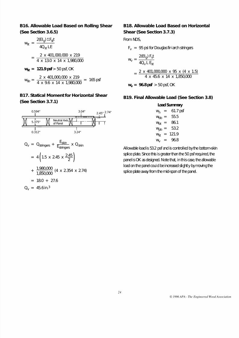
8/11/2019 DEsign and Fabrication of Plywood stressed skin panels
http://slidepdf.com/reader/full/design-and-fabrication-of-plywood-stressed-skin-panels 26/28
2 4
B16. Allowable Load Based on Rolling Shear
(See Section 3.6.5)
wst =2(EIg)ΣFstt _________
4Qst LE
=
2 x 401,000,000 x 219 ________________________ 4 x 13.0 x 14 x 1,980,000
wst = 121.9 psf> 50 psf, OK
wsb =2 x 401,000,000 x 219
= 165psf _______________________ 4 x 9.6 x 14 x 1,980,000
B17. Statical Moment for Horizontal Shear
(See Section 3.7.1)
Qv = Qstringers +Eskin x Qskin
______ Estringers
= 4(1.5 x 2.45 x 2.45) ____ 2
+1,980,000
(4 x 2.354 x 2.74) _________ 1,850,000
= 18.0 + 27.6
Qv = 45.6 in.3
B18. Allowable Load Based on Horizontal
Shear (See Section 3.7.3)
From NDS,
Fv = 95 psi for Douglas fir-larch stringers
wv =2(EI
g
) Fv
t ________ 4QvL Est
=2 x 401,000,000 x 95 x (4 x 1.5) ______________________________
4 x 45.6 x 14 x 1,850,000
wv = 96.8 psf > 50 psf, OK
B19. Final Allowable Load (See Section 3.8)
Load Summary
w∆ = 61.7 psf
wbb = 55.5wbt = 86.1
wpb = 53.2
wst = 121.9
wv = 96.8
Allowable load is 53.2psf and is controlled by the bottom-skin
splice plate. Since this is greater than the 50psf required, the
panel is OK as designed. Note that, in this case, the allowable
load on the panel could be increased slightly by moving the
splice plate away from the mid-span of the panel.
0.594" 3.04"2.45" 2.74"
5.375"
0.312" 3.24"
Neutral Axisof Panel
© 1996 APA - The Engineered Wood Assoc

8/11/2019 DEsign and Fabrication of Plywood stressed skin panels
http://slidepdf.com/reader/full/design-and-fabrication-of-plywood-stressed-skin-panels 27/28
APA RESEARCH AND TESTING
A PA – The En gin eered W ood A ssoci at ion ’s 3 7,0 00-square-foo t R esea rch
Center in Tacoma, Washington is the most sophisticated facility for basic
pa nel research an d tes tin g in th e w orld . The cen ter is staffed wi th an
experienced corps of engineers, wood scientists, an d wood product t echni-
cians. T heir research and developm ent a ssignm ents directly or indirectly
benefit all specifiers an d users of engineered wood products.
© 1996 APA - The Engineered Wood Assoc
8/11/2019 DEsign and Fabrication of Plywood stressed skin panels
http://slidepdf.com/reader/full/design-and-fabrication-of-plywood-stressed-skin-panels 28/28
We have field representatives in mostmajor U.S. cities and in Canada who can
help answer questions involving APAtrademarked products. For additional
assistance in specifying APA engineeredwood products, get in touch with your
nearest APA regional office. Call or write:
WESTERN REGI O N7011 So. 19th St. P.O. Box 11700 Tacoma, Washington 98411-0700
(253) 565-6600 Fax: (253) 565-7265
EASTERN REGI O N2130 Barrett Park Drive, Suite 102Kennesaw, Georgia 30144-3681
(770) 427-9371 Fax: (770) 423-1703
U.S. HEADQUARTERSAND INTERNATIONALMARKETING DIVISION
7011 So. 19th St. P.O. Box 11700 Tacoma, Washington 98411-0700
(253) 565-6600 Fax: (253) 565-7265
PRO DU CT SUPPORT HELP DESK(253) 620-7400
E-mail Address: [email protected]
(Offices: Antwerp, Belgium; Bournemouth,UnitedKingdom; Hamburg, Germany;Mexico City, Mexico; Tokyo, J apan.) For
Caribbean/Latin America, contactheadquarters in Tacoma.
The product use recommendatio ns in this publ icat i on a re based on APA – The Engineered Wood Association’ s continui ng programs of la boratory tes t ing, product research, and comprehensive field experi- ence. However, because the Association has no control over quality of workmanship or the conditions under which engineered wood prod ucts are used, it cannot accept responsi- bility for p roduct performance or designs as actually constructed. Because engineered wood p roduct performance requirements vary geographically, consult your lo cal archi- tect, engineer or design professional to assure compliance wit h code, construction,and performance requirements.
Form No. U813LRevised April 1996/0100
www.apawood.org
@ W
e b Add r e s s
:
Top Related