


Languages
Pages
Legal


1
Description - References
Seal Gas Booster SGB20 pneumatic drive
Seal Gas Booster SGB20-EL electric drive
Seal Gas Booster SGB20-2C double cylinder high flow pneumatic drive
Seal Gas Booster SGB20-PN/PR gland packing pneumatic drive
2 - 3
44
8
12
16
Page
Short instructions: installation - start up - shutdown 20
Contents

2 3
Seal Gas Booster
APPLICABLE STANDARDSThe applicable codes and standards are:- European Directive No. 97/23/EC (PED)- European Directive No. 94/9/EC (ATEX)- ASME VIII Div. 1- ANSI B16.34- NACE MR01.75
As an option can be added a 1-stages or a 3-stages ball valve whose function is to open/closethe seal gas inlet to the booster and the two seal gas outlets to centrifugal compressor.
3 STAGES BALL VALVE
The magnetic booster is used to ensure seal gas flow to centrifugal compressorstart-up or when compressor is in pressurized shutdown.The booster is realized as a seal-less reciprocating compressor driven by apneumatic motor.The pneumatic motor move the driving leverism jointly with a Taurus shapepermament high efficiency magnet.The piston of the reciprocating compressor is dragged by the external magneticfield without any mechanicallink. In this way the booster has a completely sealed construction without theneed of any seal system.Booster assembly shall be suitable for horizonthal or vertical mounting.Vertical mounting anyhow will be realized maintaining horizonthal movementof the booster piston.
1 STAGE BALL VALVE
Vetco Aibel x Statoil - North Sea - Visund Platform - NorwayTotalfinaelf - Akpo - NigeriaAdgas - Oag Project - Feed Gas Compressor - Das Island (Uae)Eni Petrobel - El Gamil Ph.Ii - EgyptSaipem - Webster & Stoner - AlgeriaPetrofac x Adco - Asab Cds - UaeJacobs - GermanyChevron Australia Pty Ltd., Gorgon Lng, Barrow Island, AustraliaAbb For Sonatrach, Haoud Berkaoui - AlgeriaApache North Sea Ltd., Forties Alpha Satellite Platform Project, Offshore North SeaSonatrach / Bp / Statoil - In Amenas - AlgeriaTotal E&P Uk - Laggan Tormore Project - Shetland Gas Plant - Shetland Isles - United KingdomFoster Wheeler - So.Na.Ra. - Limbe - CamerounSamsung Engineering Co.Ltd. For Gasco - Gasco Pure Case Unit 394 Onshore Gas DevelopmentPh.Iii - Habshan - UaeWorley Parson For Exxonmobil Canada Properties - Hebron Topside - Offshore Newfoundland AndLabrador - CanadaPetrobras - Cessao Onerosa - Fpso - BrazilCarigali Hess Operating Company Sdn Bhd - Cakerawala Compression Platform (Ckx) BoosterCompression Project - Malaysia / Thailand Joint Development Area
Some references
4 5
SGB20 pneumatic driveSeal Gas Booster
SERIES
SGB20
1713 3
6 14
47
14
5
32
1
6
26
24
13
310149
15
AIR VENTSNUBBER INLET(to be connected by GE/NP)Mod. SS-4SA-E/A 1/4” NPT-FAir pressure 0,2+0,8 Bar
LIFTINGEYEBOLTS
92
974 110448,5
Connector forearning bossesNo 1 Threadedhole ø M14x2
780
340
300
NO 4 THROUGHHOLES ø 20FOR BOOSTERINSTALLATION
590,5383,580
180
524
350
350
820
262
ø 3
0
Disassemblymin. 300 90 325
164
AirExhaustlubricatingoilrecovery
LUBRICATED AIR DISCHARGECONN. 1/2” NPT-F TO TANK RECOVERY
AIR VENTILATION OUT
FLUIDOUTLET
FLUIDINLET
AIRMAN SUPPLY4+9 BarConn. ø 1/2” NPT-F
*
*
* Dimension according to flange type
3/2 SOLENOIDVALVE
A
B
B
A
Functional diagram
Air filter reducer with gauge - 1/4” NPT-FD.A. pneumatic cylinder5/2 pneumatic distributorFlow regulatorManifoldAir inlet 3/2 solenoid valve 1/2” - 24 VdcBooster housingAir vent snubber element - conn. 1/4” NPT-F-Air inlet pneumatic switchOil recovery tankLubricator conn. 3/8”Air exhaust 1/4”Air exhaust 1/2”
ABCDEFGHILMNOP
HSnubber element1/4” NPT-F
Air ventexhaust
O
M
Air + oilexhaust
B
E
A
L
O G
F
P
NAir main supply Connection and location
of lubricator at Customer care
Electric supply24 Vdc
D D
CB
13
5 42
1
2
3
OPTIONAL
1
2
3
4
5
6
7
8
9
10
11
12
13
14
15
16
17
18
19
20
21
22
23
24
25
26
Housing
Cylinder
Head
Stud
Nuts
IN/Out flanges
Magnetic piston assembly
-
-
-
-
-
Pneumatic cylinder
Lifting eye
-
-
Air filter with gauge
-
-
-
-
-
-
Pneumatic distributor
-
Self-aligning joint
1
1
2
12
12
2
1
-
-
-
-
-
2
2
-
-
1
-
-
-
-
-
-
1
-
2
Pos. Description Q.ty
Identificationof the Booster
6 7
SGB20 pneumatic drive
Seal Gas Booster
SERIES SGB20
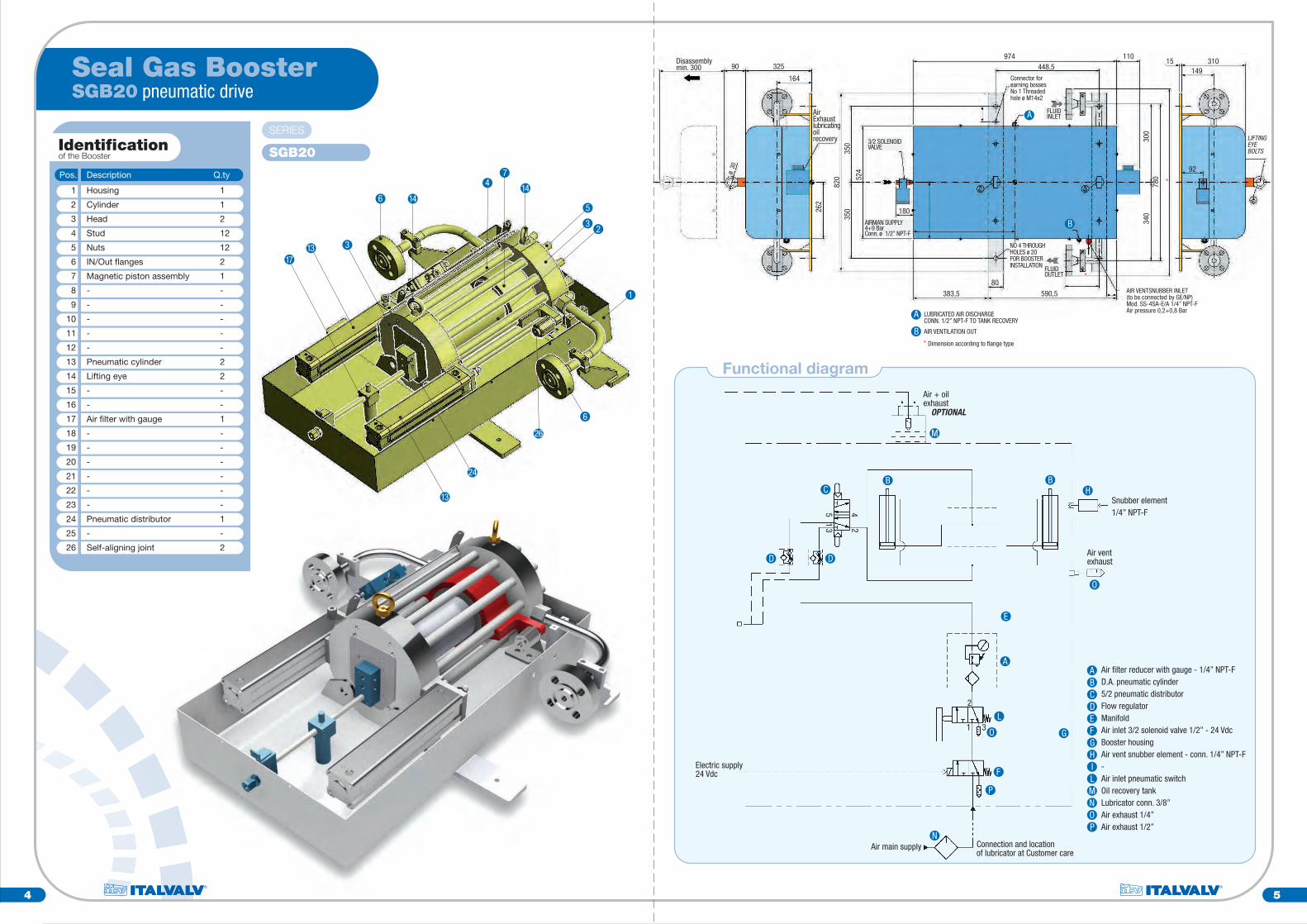
Standard Materials
FR 58/90 ED
Yes
LP Version MP Version HP Version
Nitronic 50
No
SERIES SGB20
Cylinder
Heads
O-Rings
Stud & Nuts
Connection Flanges
NACE Mr0175 Compliance
316/316L
Silicone Endura V91A
ASTM A193 B8M / ASTM 194 8M
AISI 316/316L
Yes
Bohler L334
Yes
316/316L
Technical FeaturesSERIES SGB20
Design pressure
Design standards
120 Bar-g 200 Bar-g
Ratings LP Version MP Version HP Version350 Bar-g
Process fluid
Mounting
Weight
Design temperature °C
Design flow
Boosting p (bar)
Displacement
Pneumatic cylinders consumption
Instrument air supply
Air ventilation consumption
Natural Gas or Others
Horizontal Or Wall (Vertical With Horizontal Movement Of The Piston)
Approx. K 220
Up To 80 °C / Up To 140 °C (HT Version)
7.2 Am @ 60 Cycles Per Minute
1 Bar
2000 Cm3
40 Sm3/h at 6 Bar-g air supply / 28 Sm3/h at 4 Bar-g air supply
Min.4-Norm.6-Max 9
3.5 Sm3/h
ANSI B16.34 NACE MR0175 - ASME VIII Div.1 ATEX 94/9/CE - P.E.D. 97/23/CE
DESCRIPTION TYPEBooster Inlet / Outlet
Main air supply
Air ventilation supply
Threaded type: 3/4” ANSI B1.20.11/2” NPT-F1/4” NPT-F
Standard Connections
Flanged type: 3/4” ANSI 300/600/900/1500/2500 RJ/RF
SOLENOID VALVE 3/2 - 24 Vdc/110 Vdc
AIR LUBRICATOR 3/8”
AIR TANK RECOVERY EXHAUST
Option
PNEUMATIC DRIVE
12 14 16 18 20 22 24 26 28 30 32 34 36 38 40 42 44 46 48 50 52 54 56 58 60
60
50
40
30
20
10
0
Stroke [Strokes/min]
Air C
onsu
mpt
ion
[Nm
^3/
h]
SEAL GAS BOOSTER Pneumatic Drive [Air Consumption/Stroke]
AIR CONSUMPTION CHART4 barg
4.5 barg
5 barg
5.5 barg
6 barg
6.5 barg
min.300 224 870
185
86,9
100
245
177
920
820
520
150
150
350
350
6060 20
390
390
20
820
372
min
.200
448,5
* 100 15 372172
min.100
281,5 528,5
80
60
80
A
B
C
D
E
F
WALL SUPPORTS INSTALLATION DETAIL
700
448,5
N. 4
thro
ugh
hole
s ø2
0
8 9
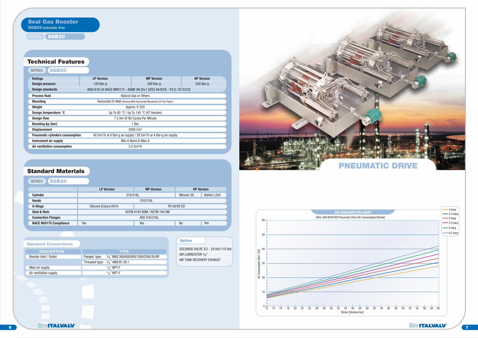
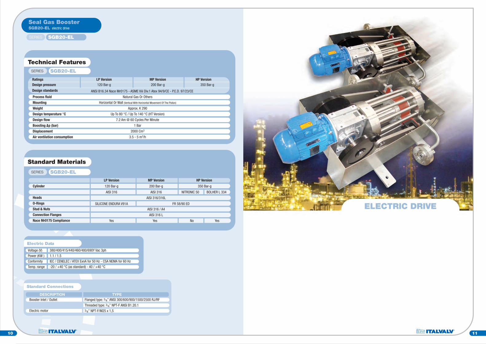
SGB20-EL electric driveSeal Gas Booster
SERIES
SGB20-EL
* Dimension according to flange type
Electric motorElectric connectionAir vent snubber element /connection at Customer care)Through holes for booster installationThreaded hole for electric ground connectionAir vent exhsaust
ABCDEF
16
143
215
20
47
5
3
1
1618
11
Functional diagram
Air ventilationexhsaust
OUTLETINLET
Electric supply
Electric motorGear reducerRod-Crank leverismMagnetic pistonAir ventilationSeal gas booster housing
ABCDEF
E
C
D
C
D
A
F
1
2
3
4
5
6
7
8
9
10
11
12
13
14
15
16
17
18
19
20
Housing
Cylinder
Head
Stud
Nuts
-
Magnetic piston assembly
-
-
-
IN/Out flanges
-
-
Lifting eye
Connecting rod
Crank
-
Gear reducer
-
Electric motor
1
1
2
12
12
-
1
-
-
-
2
-
-
2
2
2
-
1
-
1
Pos. Description Q.ty
Identificationof the Booster
10 11
SGB20-EL electric drive
Seal Gas Booster
SERIES SGB20-EL
Standard Materials
LP Version MP Version HP Version
SERIES SGB20-EL
120 Bar-g 200 Bar-g 350 Bar-g
AISI 316 AISI 316 NITRONIC 50 BOLHER L 334
AISI 316/316L
SILICONE ENDURA V91A FR 58/90 ED
AISI 316 / A4
AISI 316 L
Cylinder
Heads
O-Rings
Stud & Nuts
Connection Flanges
Nace Mr0175 Compliance Yes Yes No Yes
Electric Data
Voltage (V)
Power (KW )
Conformity
Temp. range
380/400/415/440/460/480/690Y Vac 3ph
1.1 / 1.5
IEC / CENELEC / ATEX ExnA for 50 Hz - CSA NEMA for 60 Hz
-20 / +40 °C (as standard) - 40 / +40 °C
Technical FeaturesSERIES SGB20-EL
Design pressure
Design standards
120 Bar-g 200 Bar-g
Ratings LP Version MP Version HP Version350 Bar-g
Process fluid
Mounting
Weight
Design temperature °C
Design flow
Boosting p (bar)
Displacement
Air ventilation consumption
Natural Gas Or Others
Horizontal Or Wall (Vertical With Horizontal Movement Of The Piston)
Approx. K 290
Up To 80 °C / Up To 140 °C (HT Version)
7.2 Am @ 60 Cycles Per Minute
1 Bar
2000 Cm3
3.5 - 5 m3/h
ANSI B16.34 Nace Mr0175 - ASME Viii Div.1 Atex 94/9/CE - P.E.D. 97/23/CE
DESCRIPTION TYPEBooster Inlet / Outlet
Electric motor
Standard Connections
Flanged type: 3/4” ANSI 300/600/900/1500/2500 RJ/RF
Threaded type: 3/4” NPT-F ANSI B1.20.13/4” NPT-F/M25 x 1,5
ELECTRIC DRIVE
1024
1090
LIFTING EYEø i30
LIFTING EYEø i30
545
100 588,5 501,5
60 80 80
550
267
100
Air exsaust
Airfilter+lubricator
Solenoidvalve 3/2”
140
900
Air lubricatingexsaust tank
No 1threaded hole ø M14for electric ground conn.
Air vent inlet snubberto be connected by Customer
656
980
700
700
980
448,5
AIR MAINSUPPLY10
0
5021
0
287
570
BOOSTER INSTALLATION DETAIL
No 4 throughholes ø 20
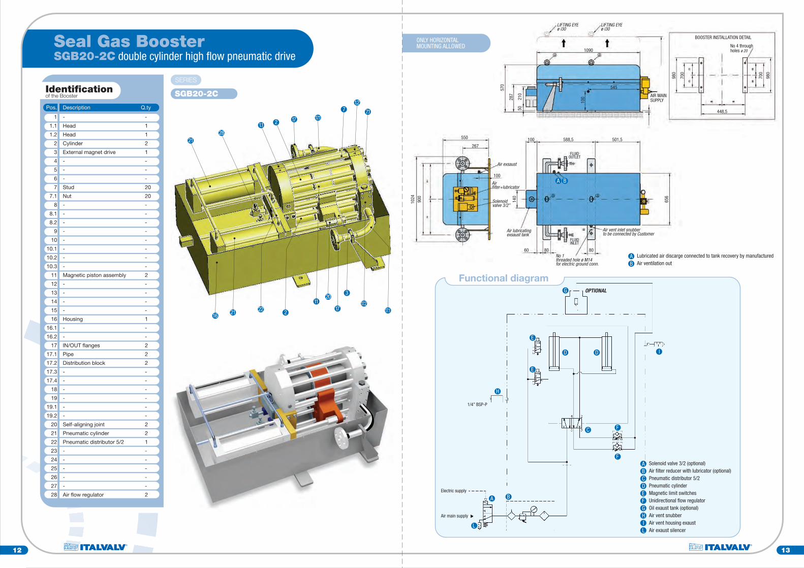
Lubricated air discarge connected to tank recovery by manufacturedAir ventilation out
AB
A B
FLUIDINLET
FLUIDOUTLET
12 13
SGB20-2C double cylinder high flow pneumatic driveSeal Gas Booster
SERIES
SGB20-2C
2128
1.1 2 17 17.1
1.27 7.1
11 17.2
3
17.1172
20
2221
ONLY HORIZONTALMOUNTING ALLOWED
1/4” BSP-P
Electric supply
Air main supply
Functional diagram
Solenoid valve 3/2 (optional)Air filter reducer with lubricator (optional)Pneumatic distributor 5/2Pneumatic cylinderMagnetic limit switchesUnidirectional flow regulatorOil exaust tank (optional)Air vent snubberAir vent housing exaustAir exaust silencer
ABCDEFGHIL
G
E
D D
E
H
I
F
F
C
A B
L
OPTIONAL
16
1
1.1
1.2
2
3
4
5
6
7
7.1
8
8.1
8.2
9
10
10.1
10.2
10.3
11
12
13
14
15
16
16.1
16.2
17
17.1
17.2
17.3
17.4
18
19
19.1
19.2
20
21
22
23
24
25
26
27
28
-
Head
Head
Cylinder
External magnet drive
-
-
-
Stud
Nut
-
-
-
-
-
-
-
-
Magnetic piston assembly
-
-
-
-
Housing
-
-
IN/OUT flanges
Pipe
Distribution block
-
-
-
-
-
-
Self-aligning joint
Pneumatic cylinder
Pneumatic distributor 5/2
-
-
-
-
-
Air flow regulator
-
1
1
2
1
-
-
-
20
20
-
-
-
-
-
-
-
-
2
-
-
-
-
1
-
-
2
2
2
-
-
-
-
-
-
2
2
1
-
-
-
-
-
2
Pos. Description Q.ty
Identificationof the Booster

14 15
SGB20-2C double cylinder high flowpneumatic drive
Seal Gas Booster
SERIES SGB20-2C
SOLENOID VALVE 3/2 - 24 Vdc/110 Vdc
AIR FILTER REDUCER 1/2”
AIR LUBRICATOR 1/2”
AIR EXHAUST RECOVERY
Option
Technical FeaturesSERIES SGB20-2C
120 Bar-g 200 Bar-g
Series
Design pressure
Design standards
LP Version MP Version HP Version350 Bar-g
ASME VIII div.1 - ASME B16.34 Ed. 2004 - 97/23/EC P.E.D. - 94/9/EC ATEX
Process fluid
Mounting
Weight
Design temperature °C
Design flow
Boosting p (bar)
Displacement
Pneumatic cylinders consumption
Instrument air supply (Bar-g)
Air ventilation consumption
Natural gas or other
Horizontal (Mandatory)
Approx. Kg. 600
140 for magnets
12 Am3/h @ 50 cycles per minute
1
4000 cm3
1555 Sm3/h @ 6 Bar-g air supply / 110 Sm3/h @ 4 Bar-g air supply
Min. 4 °© Norm. 6 - Max 9
10.8 Sm3/h
Standard Materials
LP Version MP Version HP Version
SERIES SGB20-2C
AISI 316LHousing
Cylinder (double)
Head
Gaskets
Bolting
IN/OUT connection flanges
AISI 316L NITRONIC 50 BOLHER L334
AISI 316L
ENDURA V91A ED FR 58/90
B8M / A4
AISI 316L
DESCRIPTION TYPEBooster Inlet / Outlet
Main air supply
Air ventilation supply
Standard Connections
Flanged type: 3/4” ANSI 300/600/900/1500/2500 RJ - RF
Threaded type: 3/4” NPT-F ANSI B1.20.1 1/2” NPT-F1/2” NPT-F1/4” NPT-F
DOUBLE CYLINDERHIGH FLOW PNEUMATIC DRIVE
12 14 16 18 20 22 24 26 28 30 32 34 36 38 40 42 44 46 48 50 52 54 56 58 60
6050403020100
Stroke [Strokes/min]
Air C
onsu
mpt
ion
[Nm
^3/
h]
SEAL GAS BOOSTER Double Cylinder Pneumatic Drive [Air Consumption/Stroke]
AIR CONSUMPTION CHART
708090
100110120130140150160170180190200210
4 barg
4.5 barg
5 barg
5.5 barg
6 barg
6.5 barg

INLET/OUTLET1” W.N. FLANGESSCHEDULE No 160s
240
280
1420
550 870
394
215 650
AIR SUPPLY CONN 1/2 NPT-F
ø 32
5
350
184
No 4HOLESø 20
PROTECTION CABINET
256LEAK-OFFø 1/4” NPT-F
LIFTINGEYELET ø 30
740
LUBRICATOR CONN 1/4”(at customer care)
220
220
200
PNEUMATIC CYLINDERFLUID
OUTLET
FLUIDINLET
ø 20,7
ø 33,4
37° 3
0°
45°
16 17
SERIES
SGB20-PN/PR
421
18 1 2.1 2.23
5
2
11
13122032
1533
32
AIR INLETCONN. 1/2” NPT-F
Functional diagram
C
B
AD.A. Pneumatic cylinder5/2 Double pilot pneumatic distributorFlow regulator
ABC
PRINCIPLE OF OPERATIONWhen the Seal Gas Booster is powered pneumatically, thepiston in the pneumatic cylinder double acting, connectedto the piston in the high pressure cylinder by means of aconnecting rod, it reciprocates the high pressure pistoncompressing the gas contained in it coming from the processconnection of the flange input, creating in this way acontinuous flow and a pressure differential drop betweeninlet and outlet of the Seal Gas Booster.
LEAK-OFFCONNECTION
1/4”NPT-F
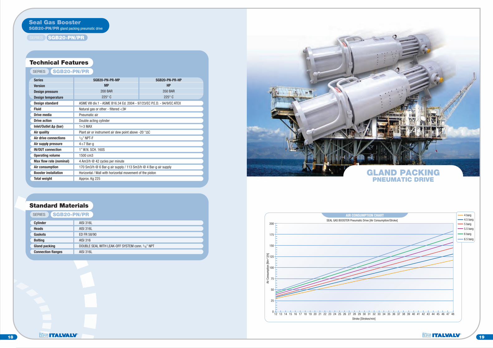
SGB20-PN/PR gland packing pneumatic driveSeal Gas Booster
1
2
2.1
2.2
3
4
5
6
7
8
9
10
11
12
13
14
15
15.1
16
17
18
19
20
21
22
23
24
25
26
27
28
29
30
31
32
33
34
35
Cylinder
Drive side head
Head
Upper head
Stud
-
In/Out flanges
-
-
-
-
-
Supports
Self-aligning joint
High pressure piston stem
-
Pneumatic cylinder
-
-
-
Leak-off
-
Pneumatic distributor
Flow regulator
-
-
-
-
-
-
-
-
-
-
Pneumatic piston head
Stud
-
-
1
1
1
1
16
-
2
-
-
-
-
-
2
1
1
-
1
-
-
-
1
-
1
1
-
-
-
-
-
-
-
-
-
-
2
4
-
-
Pos. Description Q.ty
Identificationof the Booster
18 19
SGB20-PN/PR gland packing pneumatic drive
Seal Gas Booster
SERIES SGB20-PN/PR
Technical FeaturesSERIES SGB20-PN/PR
ASME VIII div.1 - ASME B16.34 Ed. 2004 - 97/23/EC P.E.D. - 94/9/EC ATEX
Natural gas or other - filtered <3
Pneumatic air
Double acting cylinder
1 3 MAX
Plant air or instrument air dew point above -20 °∆C1/2” NPT-F
4 7 Bar-g
1” W.N. SCH. 160S
1500 cm3
4 Am3/h @ 42 cycles per minute
170 Sm3/h @ 6 Bar-g air supply / 113 Sm3/h @ 4 Bar-g air supply
Horizontal / Wall with horizontal movement of the piston
Approx. Kg 225
MP
200 BAR
225° C
SGB20-PN-PR-MPSeries
Version
Design pressure
Design temperature
Design standard
Fluid
Drive media
Drive action
Inlet/Outlet p (bar)
Air quality
Air drive connections
Air supply pressure
IN/OUT connection
Operating volume
Max flow rate (nominal)
Air consumption
Booster installation
Total weight
HP
350 BAR
225° C
SGB20-PN-PR-HP
Standard MaterialsSERIES SGB20-PN/PR
AISI 316L
AISI 316L
ED FR 58/90
AISI 316
DOUBLE SEAL WITH LEAK-OFF SYSTEM conn. 1/4” NPT
AISI 316L
Cylinder
Heads
Gaskets
Bolting
Gland packing
Connection flanges
GLAND PACKINGPNEUMATIC DRIVE
12 13 14 15 16 17 18 19 20 21 22 23 24 25 26 27 28 29 30 31 32 33 34 35 36
100
75
50
25
0
Stroke [Strokes/min]
Air C
onsu
mpt
ion
[Nm
^3/
h]
SEAL GAS BOOSTER Pneumatic Drive [Air Consumption/Stroke]
AIR CONSUMPTION CHART 4 barg
4.5 barg
5 barg
5.5 barg
6 barg
6.5 barg
125
150
175
200
37 38 39 40 41 42 43 44 45 46 47 48

20
Only qualified personnel can install the device. When coupling, follow the security standard in force for thiskind of operation both for personnel and machinery. In detail, follow every particular prescription indicated inthis instruction handbook.Anyway, respect the following prescriptions:Before assembling check the Seal Gas Booster preservation state.Qualified personnel must assemble the pneumatic and mechanical parts.Respect every safety standard in force when connecting to energy sources (electrical, pneumatic, and so on).Install the Seal Gas Booster to the floor in horizontal position or wall position keeping horizontal movementof the piston.Lock the Seal Gas Booster to the plan using the relevant holes by designed screws or tie rod.Connect the main air supply to the inlet threaded connection in the front side of the seal gas booster. and alsothe air ventilation to the ventilation device (pressure reducer or snubber element) located in the left side ofthe booster housing.WARNING: For the correct operation of the seal gas booster the connection of the air ventilation is mandatory!WARNING: For the high temperature booster HT series the air ventilation must always be present even if thebooster is not operational!Connect the pipe media to the lateral flanges blocking the tie rods operating in cross after having installed thering joint gaskets.WARNING: Make sure that INLET / OUTLET flow direction indications are respected to grant the correctworking of the system!WARNING: use only filtered process fluid not to damage the System Booster (3µ grade min. suggested).
Short Instructions
Before the Seal Gas Booster starts check its correct functionality:• Check if the pneumatic connections are correct.• Check if the air supply medium (pneumatic drive booster) or the electric power supply (electric drive booster)
are correct.Only for pneumatic drive booster: use only filtered and lubricated air.• Max. pressure and temperature values must not exceed the nameplate data,• Check if the Seal Gas Booster movement is regular (cycles/min) as indicated on the system nameplate data.• Check the air ventilation correct setting (0.2÷0.8 bar suggested) applied to the ventilation device (reducer
pressure or snubber element).
START-UP1. Connect the ventilation air supply (pressure reducer or snubber element).2. Connect the power supply drive (air or electric) of the booster.3. Connect the process gas fluid to the inlet booster increasing gradually the fluid pressure up to the operating
value.
SHUTDOWN1. Disconnect the inlet process gas fluid decreasing the pressure gradually.2. Disconnect the power supply drive of the booster (air or electric).3. Disconnect the ventilation air supply (pressure reducer or snubber element).
PNEUMATIC DRIVE SEAL GAS BOOSTERSTANDARD TESTS AND INSPECTIONS
POS. TESTING AND INSPECTION REF. SPECIFICATIONS OR STANDARD SUPPLIER
TYPE APPLICABLE TO PROCEDURE ACCEPTABILITY
Chemical analysis andmechanical properties
Visual and dimensionalinspection
Hydraulic test
Functional test
Check complianceof materials
Inspections of certificateand documentation
Parts under pressure
Assembled booster
Cylinder
Assembled booster
Only for explosion-proofaccessories
ASTM or applicablematerial specification
Construction drawings
ITALVALV Standard
ITALVALV Standard
ASTM or applicablematerial specification
Construction drawings
No leaks allowed
ITALVALV Standard
Check spec. requirements
ITALVALV Standard
Procedure
1
2
3
5
6
7
Pneumatic leakage test Cylinder ITALVALV Standard No leaks allowed4
ELECTRIC DRIVE SEAL GAS BOOSTERSTANDARD TESTS AND INSPECTIONS
POS. TESTING AND INSPECTION REF. SPECIFICATIONS OR STANDARD SUPPLIER
TYPE APPLICABLE TO PROCEDURE ACCEPTABILITY
Chemical analysis andmechanical properties
Visual and dimensionalinspection
Hydraulic test
Routine Test
Functional test
Check complianceof material
Parts under pressure
Assembled booster
Cylinder
Assembled booster
Only for explosion-proofaccessories
ASTM or applicablematerial specification
Construction drawings
ITALVALV Standard
Manufacturer Standard
ASTM or applicablematerial specification
Construction drawings
No leaks allowed
Manufacturer Standard
ITALVALV Standard
Check spec. requirements
1
2
3
5
6
7
Inspections of certificateand documentation
8
Only for explosion-proofaccessories
ITALVALV Standard
ITALVALV Standard
Procedure
Pneumatic leakage test Cylinder ITALVALV Standard No leaks allowed4
Installation
Testing
System start-up - Shutdown

Series
E d i t e d 2 0 1 4
SGB20
Seal GasBooster
Seal GasBooster
SGB20-EL
SGB20-PN/PR
SGB20-2C
Top Related