


Languages
Pages
Legal


Datalink8 Copyright 1998, Professor John T. Gorgone 1
DATA LINK LAYER
DATA LINK CONTROL PROTOCOLS

Datalink8 Copyright 1998, Professor John T. Gorgone 2
GOALS OF THE DATA LINK CONTROL LAYER
n To provide the basic communication function of moving information blocks over an unreliable communication channel and detecting bit errors introduced by the channel.
n To mange the orderly transmission and reception on channel with multiple attached transmitters and/or receivers.
n To be efficient, high performing and utilize the maximum available bandwidth of the communication channel.
n To be easy to implement, within hardware and by small microcomputers.

Datalink8 Copyright 1998, Professor John T. Gorgone 3
DATA LINK PROTOCOLS
Grammar of data communication.
Rules and procedures for control of data communication links.
Etiquette of data exchange on a communications link.

Datalink8 Copyright 1998, Professor John T. Gorgone 4
ELEMENTS OF NETWORK PROTOCOL
1. SyntaxCode and character setBlock structureMessage length and typeFramingCommand format
2. SemanticsHandshakingIdentificationInformation TransferTransparency ControlError controlTermination
3. TimingSynchronizationPrecedenceOrder of transmissionSequence controlFlow controlTime-out control

Datalink8 Copyright 1998, Professor John T. Gorgone 5
Requirements for communications between directly connected stations.
• Frame synchronization• Variety of line configurations
• Flow control
• Error control• Addressing
• Link management
• Control and data on same link

Datalink8 Copyright 1998, Professor John T. Gorgone 6
The data link control layer/protocol provides an envelope for the transmission of message blocks over a communication channel.It detects bit error introduced by the communication channel anddelivers only good blocks (those without errors).Basic functions performed by data link protocols are:
Framing of informationBit error detection
DATA LINK CONTROL FUNCTIONS
DataLink
Protocol
MessageBlocks
MessageBlocks
Communication Channel
DataLink
Protocol

Datalink8 Copyright 1998, Professor John T. Gorgone 7
ADDITIONAL DATA LINK CONTROL FUNCTIONS
n Error Correction
n Sequencing
n Receipt and Flow Control
– The correction of information blocks with bit errors and delivery of all blocks.
– The delivery of all blocks in proper sequence, without missing blocks or duplicate blocks, even when correcting for bit errors.
– The notification to the sender of the proper delivery of information blocks and control by the destination on the rate of information flow.

Datalink8 Copyright 1998, Professor John T. Gorgone 8
CONTROL FUNCTIONS (Continued)
n Addressing
n Pipelining and Performance
n Priority
n Security
– The addressing of an information block to one, some, or all possible destinations.
– The ability to send multiple blocks through the communication channel simultaneously and the ability of the link control layer to specify performance characteristics (delay, throughput).
– An interface to queue and order messages for transmission.
– The protection of data being sent over the channel.

Datalink8 Copyright 1998, Professor John T. Gorgone 9
DATA LINK CONTROL INFORMATION RESTRICTIONS
n Block Size
n Information representation
n Physical Channel Requirements
n Topology Constraints
– The maximum and minimum size data blocks accepted by the data link control mechanism.
– The codes sets, byte sizes and information formats accepted by the mechanism.
– The required characteristics of the physical media.
– Restriction on the paths of data flow due to the location of users and their connected channels.

Datalink8 Copyright 1998, Professor John T. Gorgone 10
STAND ALONE USE
Data link control protocols can also be used by themselves (outside network architectures) to create a single error free sequential path between two computers and/or devices.
DataLink
ProtocolUnreliable Channel
DataLink
Protocol
Reliable Sequential Path

Datalink8 Copyright 1998, Professor John T. Gorgone 11
RELATIONSHIP TO NETWORK ARCHITECTURE
Link control protocols (Modules) can be thought of as black box creating a sequential error - free data link from a channel that has some probability of introducing errors.
They are used within network architecture structures to create error-free paths between nodes connected by data channels. These point to point paths are used by the higher level layer to create end to end paths.
SwitchSwitchPT TO PT PATH PT TO PT PATHNode Node
PT TO PT PATH
End to End Path

Datalink8 Copyright 1998, Professor John T. Gorgone 12
Topology of a Data Link refers to the Physical Arrangement of stations in a link.
TOPOLOGY
Computer(Primary)
(1.) Point-to-Point
Computer
(2.) Multipoint or Multidrop
Secondary Device
SS
SSSS
SSS S S S

Datalink8 Copyright 1998, Professor John T. Gorgone 13
Duplexity of a link refers to the direction and timing of the signal flow.
DUPLEXITY
Simplex One direction
Half-Duplex Two-way alternate
Full-Duplex Two-way simultaneous

Datalink8 Copyright 1998, Professor John T. Gorgone 14
DATA LINK CONFIGURATIONS
P S
P transmits while S receives
P S
P receives while S transmits
P S
Both stations can transmit while they receive
(a) Half-Duplex (b) Full DuplexPoint-to-Point Point-to-Point

Datalink8 Copyright 1998, Professor John T. Gorgone 15
DATA LINK CONFIGURATIONS (Continued)
(c) Multi-multipoint (e) Multipoint Duplex
P S1
S2
S3
P S1
S2
S3
FDX FDXFDXHDX

Datalink8 Copyright 1998, Professor John T. Gorgone 16
DATA LINK CONFIGURATIONS (Continued)
(d) Multi-point half-duplex
P S1
S2
S3
P S1
S2
S3
HDX HDX HDX HDX

Datalink8 Copyright 1998, Professor John T. Gorgone 17
THREE PHASES OFCOMMUNICATION CONTROL
n Establishment
n Data Transfer
n Termination

Datalink8 Copyright 1998, Professor John T. Gorgone 18
Station 1 Station 2 Station 2 Station 1
Establishment
Data Transfer
Termination
ENQ
NAK ACK
NAK ACKInvalid orno reply
Invalid orno reply
Error Recovery
Error Recovery
Frame
EOTPoint-to-Point HDX

Datalink8 Copyright 1998, Professor John T. Gorgone 19
POLLING = PERMISSION
Primary Secondary Primary Secondary
Poll Poll
NAKData
ACK
Polled terminal hasnothing to send
Polled terminal hasdata to send
Multipoint link with one station as a primary station

Datalink8 Copyright 1998, Professor John T. Gorgone 20
Primary Secondary
Select
ACK
Data
ACK
Select
Primary Secondary
Select+
Data
ACK
Fast select
SELECTION = TO SEND DATA
Datalink8 Copyright 1998, Professor John T. Gorgone 21
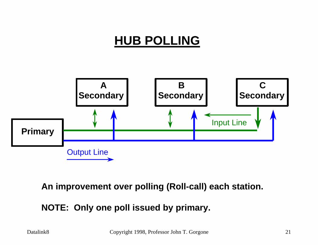
HUB POLLING
Secondary
Primary
SecondarySecondary
Output Line
Input Line
A B C
An improvement over polling (Roll-call) each station.
NOTE: Only one poll issued by primary.

Datalink8 Copyright 1998, Professor John T. Gorgone 22
CONTENTION
n Contention is another form of line discipline.
n No primary station.
n All stations are peer (equal) stations.
n Any station may transmit if the line if free.
n Both transmitter and receiver stations must be identified (an address is needed for each).

Datalink8 Copyright 1998, Professor John T. Gorgone 23
ADDRESS IMPLICATIONSFOR LINE DISCIPLINE
Point-to-Point:No address is needed
Primary-Secondary Multipoint:One address is needed to identify the secondary station
Peer Multipoint:Two addresses are needed
Primary (Sender or/Transmitter)Secondary (Receiver(s))

Datalink8 Copyright 1998, Professor John T. Gorgone 24
FLOW CONTROL
Assures that a transmitting station does not overwhelm a receiving station with data.
Stop-and-Wait
n Each frame of data is acknowledgedn Only one frame outstanding
Sliding Window
n Station may send frames from an allowable "Window"n Multiple frames outstandingn Numbered frames
1.
2.

Datalink8 Copyright 1998, Professor John T. Gorgone 25
t0
+at0
+1t0
+1+a
+1+2at0
t0
+1t0
+at0
+1+at0
+1+2at0
t0

Datalink8 Copyright 1998, Professor John T. Gorgone 26
The bit length (distance to travel) is less than the frame length (message) or the frame length is greater than the bit length. Example: LANS
The frame length (message) is less than the bit length (distance to travel) or the bit length is greater than the frame length. Example: Satellite

Datalink8 Copyright 1998, Professor John T. Gorgone 27
ExampleStop-and-wait Protocol1000-bit frame1 megabit satellite channel
Time(Millisecond) Event
0 A starts sending frame1 Last bit sent; A waits
270 1st bit arrives at B271 Last bit arrives at B271 B send ACK541 ACK arrives at A
1. How long does station A wait ? ms?2. What is the channel utilization = ? %?

Datalink8 Copyright 1998, Professor John T. Gorgone 28
ExampleStop-and-wait1000-bit frame1 megabit satellite channel
Time(Millisecond) Event
0 A starts sending frame1 Last bit sent; A waits
270 1st bit arrives at B271 Last bit arrives at B271 B send ACK541 ACK arrives at A
1. How long does station A wait = 541-1 = 540ms 2. What is the channel utilization =1/541 or <1%

Datalink8 Copyright 1998, Professor John T. Gorgone 29
Sliding Window Protocol
• With stop & wait protocol serious inefficiencies of link utilization will occur if the bit length of the link is greater than the frame length.
• To improve link utilization multiple frames must be in transit at one time.
• This technique is known as the sliding window protocol.
Datalink8 Copyright 1998, Professor John T. Gorgone 30
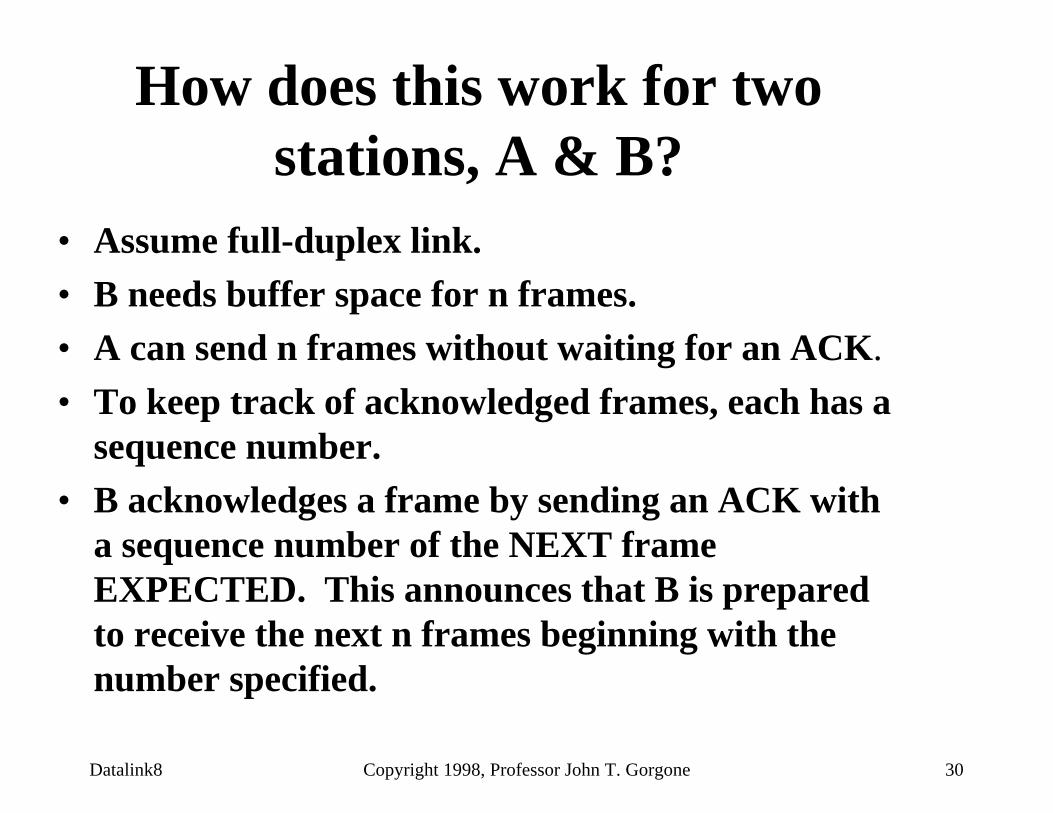
How does this work for two stations, A & B?
• Assume full-duplex link.• B needs buffer space for n frames.• A can send n frames without waiting for an ACK.
• To keep track of acknowledged frames, each has a sequence number.
• B acknowledges a frame by sending an ACK with a sequence number of the NEXT frame EXPECTED. This announces that B is prepared to receive the next n frames beginning with the number specified.

Datalink8 Copyright 1998, Professor John T. Gorgone 31
Sliding Window continued
• Multiple frames can be acknowledged with this scheme.
• A keeps a list of sequence numbers it is allowed to send.
• B keeps a list of sequence numbers it is prepared to receive.
• These lists are thought of as a window of frames, hence the name: Sliding Window Flow Control.
Datalink8 Copyright 1998, Professor John T. Gorgone 32
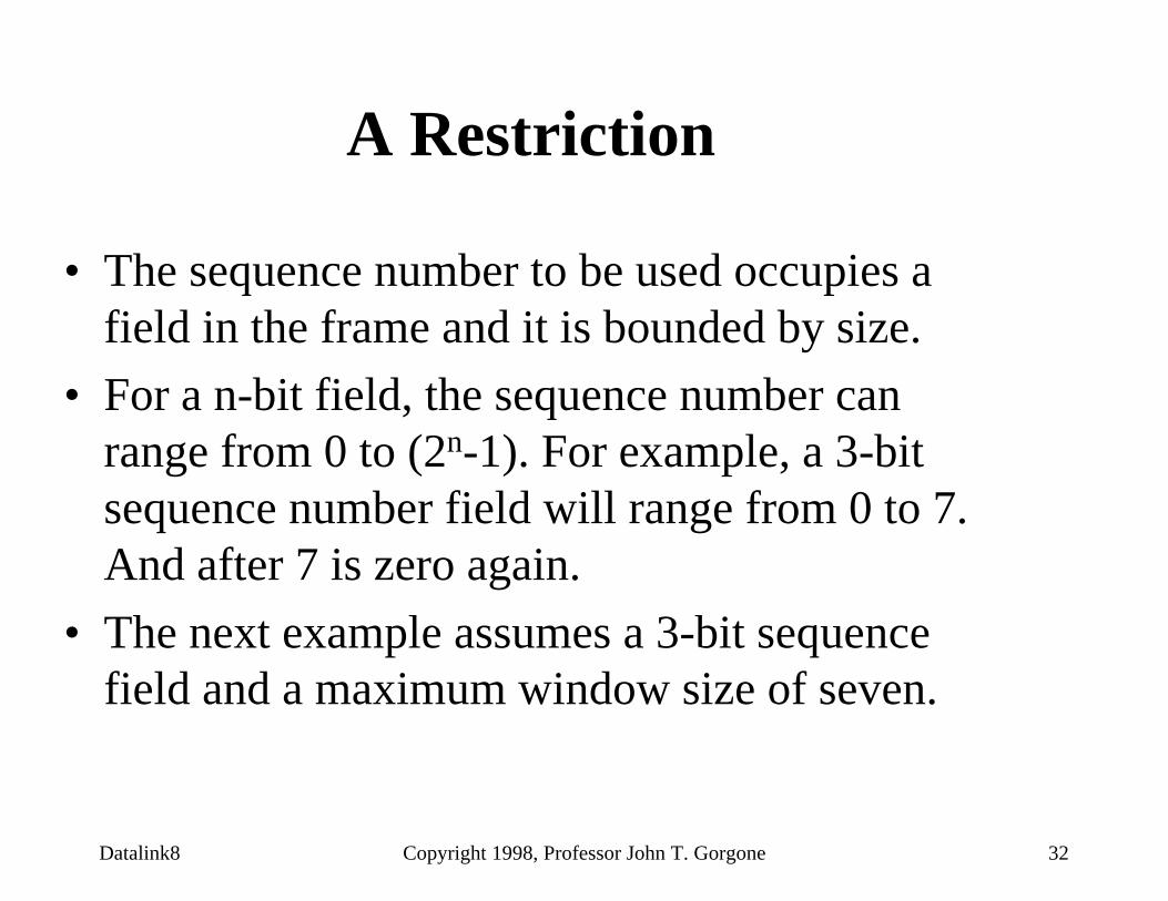
A Restriction
• The sequence number to be used occupies a field in the frame and it is bounded by size.
• For a n-bit field, the sequence number can range from 0 to (2n-1). For example, a 3-bit sequence number field will range from 0 to 7. And after 7 is zero again.
• The next example assumes a 3-bit sequence field and a maximum window size of seven.

Datalink8 Copyright 1998, Professor John T. Gorgone 33
A may send 7 of 8 frames.Frame #s 0,1,2,3,4,5,6,7
Sending Machine A Sending Machine B
A shrinks its list witheach transmission. A can still send 4 more frames,#s 3,4,5,6.
A expands its counter witheach acknowledgment andmay send 7 frames starting with #s 3,4,5,6,7,0,1. A sends #s 3 thru 0 and shrinks its list to one frame, sequence #1. A can send only one more frame.
In the mean time, A receives ACK4 and expands its counter.
A may now only send 2 more frames.
B is prepared to receive7 frames. Frames #s 0,1,2,3,4,5,6
B acknowledges all3 frames (ACK3) and adjustsits list to receive 7more. Frame #s 3,4,5,6,7,0,1.
Ns = Sequence No. of frame sent
Nr = Sequence No. of next frame Expected
Nr = 4
Ns = 7
Ns = 0
Ns = 3
Ns = 4
Ns = 5
Ns = 6
Nr = 3
Ns = 0
Ns = 2
Ns = 1
Ns = 2
Ns = 1
SLIDING WINDOW FLOW CONTROL
ACK3
ACK4
B decides to limit the flow of frames and sends an ACK4.
It adjusts its list to receive 7 frames, #s 4,5,6,7,0,1,2

Datalink8 Copyright 1998, Professor John T. Gorgone 34
1. Sender transmits 8 frames, frame #s 0 - 7.2. All 8 frames arrive and are ACKnowledged.3. All ACKs for the 8 frames are lost.4. Sender must Time Out and Retransmit frame #s 0 - 7.5. Receiver unknowingly accepts the 8 DUPLICATE frames!
Why can you only send 7 of 8 frames at any one time?
Example

Datalink8 Copyright 1998, Professor John T. Gorgone 35
1. Sender transmits 8 frames, 0 - 7.2. All 8 frames arrive and are ACKnowledged.3. All 8 ACKs are lost.4. Sender must Time Out and Retransmit frames #s 0 - 7.5. Receiver unknowingly accepts the 8 DUPLICATE frames!
Why can you only send 7 of 8 frames at any one time?
Example
Solution: Restrict the window size to 2 - 1 or 7 outstanding frames.
2 - 1 XXX = 3 position field son = 3
2 - 1 = 2 - 1= (2 X 2 X 2) - 1= 8 - 1= 7
n
n
n
3

Datalink8 Copyright 1998, Professor John T. Gorgone 36
To determine the maximum window size use 2 - 1.
For a 3-bit position field it is 7.
For a 6-bit position field:
Max. window size: 2 - 164 - 163
For a 7-bit position field it would be: 2 - 1128 - 1127
n
6
7

Datalink8 Copyright 1998, Professor John T. Gorgone 37
ERROR CONTROL
Automatic Repeat Request (ARQ)
n Positive Acknowledgment (ACK)
n Negative Acknowledgment (NAK)
n Time-out - Retransmit Frame
n Frame Labeling

Datalink8 Copyright 1998, Professor John T. Gorgone 38
ERROR CONTROL TECHNIQUES
nStop-and-Wait ARQnFrames numbered 0,1
nContinuous ARQ
Go-Back-NSelective Repeat

Datalink8 Copyright 1998, Professor John T. Gorgone 39
1
1
1
0
0
0
A B
A B
A B
1
1
NAK1
Frames queued for transmission
1
1
1
Frames awaitingACK/NAK
Frames intransit
Frames Retained
Frame 1retransmitted
Frame 1in error,
NAK1 sent
(a) Stop-and-Wait ARQ
Datalink8 Copyright 1998, Professor John T. Gorgone 40
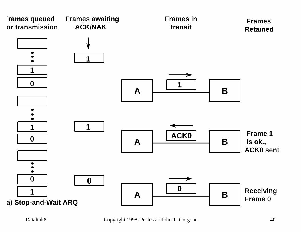
1
1
0
0
1
0
A B
A B
A B
1
0
ACK0
Frames queued for transmission
0
1
1
Frames awaitingACK/NAK
Frames intransit
Frames Retained
Receiving Frame 0
Frame 1is ok.,
ACK0 sent
(a) Stop-and-Wait ARQ

Datalink8 Copyright 1998, Professor John T. Gorgone 41
7
6
5
43
2
1
7
654
3
2
7
654
3
2
A B 1
ACK 2
4 3 2
A B 1
NAK 2
5 4 3
A B 1
ACK 5
4 3 2
Retransmit
Frame 2 in error,NAK2 is sent and
Frame 3, 4 and5 are discarded
(b) Go-Back-N Continuous ARQ
Frames queued for transmission
Frames awaitingACK/NAK
Frames intransit
Frames Retained

Datalink8 Copyright 1998, Professor John T. Gorgone 42
0 1 2 3 4 5 32 4 65 7 0
0 1 32 4 65E D D D
ACK 1 ACK 2 NAK 2 ACK 3 ACK 4 ACK 5 ACK 6
Error DiscardedFrames

Datalink8 Copyright 1998, Professor John T. Gorgone 43
7
6
5
43
2
1
7
654
3
2
3
2
76
5
4
A BACK 2
4 3 2
A BACK 6
7 6 2
A BNAK 2
5 4 3
(c) Selective-repeat Continuous ARQ
Frames queued for transmission
Frames awaitingACK/NAK
Frames intransit
Frames Retained
543
1
1
1
Frame 1 is valid,ACK 2 sent
Frame 2 is in error, NAK2is sent
Frame 3,4 and 5retained until 2arrives correctlyand ACK6 willacknowledge2, 3, 4 and 5

Datalink8 Copyright 1998, Professor John T. Gorgone 44
SELECTIVE REPEAT ARQ
0 1 2 3 4 5 2 6 7 0
0 1 3 4 5 2 6E
ACK 1 ACK 2 NAK 2 ACK 6
Error Buffered byReceiver
Frames 2-5released
NOTE: CUMULATIVE ACKs are not used becauseframes may be accepted out of order.

Datalink8 Copyright 1998, Professor John T. Gorgone 45
WINDOW SIZE FOR SELECTIVE REPEAT Example
1. Sender transmit frame #s 0 thru 6.2. Receiver ACKs all seven frames.3. All ACKs are lost.4. Sender T.O. and retransmit frame #s 0 thru 6.5. Receiver ready to accept new frame #s 7, 0, 1, 2, 3,
4, 5 (sequence numbers 7 - 13).6. Receiver assumes that frame #s 0 thru 5 are new
frames when in fact they are duplicates.

Datalink8 Copyright 1998, Professor John T. Gorgone 46
SOLUTION
Restrictive window size:
Maximum window size should be NO MORE THAT 1/2 THE RANGE OF THE SEQUENCE
NUMBERS.
If range is 0 - 7, then (1/2 * 8/1) only 4 frames can be outstanding.

Datalink8 Copyright 1998, Professor John T. Gorgone 47
Restrictive Window Size For Selective Repeat
Example
1. Sender transmit frame #s 0 thru 3.2. Receiver ACKs all four frames.3. All ACKs are lost.4. Sender T.O. and retransmit frame #s 0 thru 3.5. Receiver ready to accept new frames #s 4,5,6,7
(sequence numbers 4 - 7).6. Receiver discards frame #s 0 thru 0 as duplicates
since it is waiting on frame #4.7. Receiver sends ACK4.

Datalink8 Copyright 1998, Professor John T. Gorgone 48
BIT-ORIENTED LINK CONTROL PROTOCOLS
n HDLC = High-level Data Link Control (ISO 3309, ISO 4335)
n ADCCP = Advanced Data Communication Control Procedures.(ANSI X3.66), -- Same as HDLCAdopted by U.S. National Bureau of Standards(FIPS PUB 71-1) and by Federal TelecommunicationsStandards Committee (FED-STD-1003A)
n LAP-B = Link Access Procedure, Balanced(ITU-T/CCITT) -- Subset of HDLC and is part of the X.25packet-switched network standard.
n SDLC = Synchronous Data Link Control(IBM) -- Subset of HDLC but is not a standard

Datalink8 Copyright 1998, Professor John T. Gorgone 49
EXAMPLES OF CHARACTER ORIENTED PROTOCOLS
ANSI-DLC (x3.28)
ECMA-16, and ISO IS1745
IBM BSC
IATA SLC
DEC DDCMP
Basic mode control procedures for data communication systems
Binary Synchronous Communication
Synchronous Link Control
Digital Data Communications Message Protocol (Byte count oriented)
1.
2.
3.
4.
5.

Datalink8 Copyright 1998, Professor John T. Gorgone 50
ANSI X34-1976COMMUNICATIONSCONTROLCHARACTERS
CHARACTER MEANING CODE(H…I)
SOHSTXETXEOTENQACKDLENAKSYNETB
Start of Heading Start of TextEnd of TextEnd of TransmissionEnquiryAcknowledgment Data Link Escape Negative ACK Synchronous IdleEnd of Transmission Block
Block
00000010000010000001100001000000101000011000100000010101001011000101110010111

Datalink8 Copyright 1998, Professor John T. Gorgone 51
OTHER COMMUNICATIONCHARACTERS
DLE< Reverse InterruptDLE; WACK (Wait Positive Acknowledgment)DLE= Start of Transmission Block
DC1 XOnDC3 XOffDC2 Enable PeripheralDC4 Disable Peripheral

Datalink8 Copyright 1998, Professor John T. Gorgone 52
HDLC Basic Characteristics
n Three station types:n Primary Station, Secondary Station, and
Combined Stationn Two link configurations:
n Unbalanced: for point-to-point & multipointoperations
n Balanced: used only in point-to-point operations
n Three data transfer modes of operation:n NRM, ABM, and ARM

Datalink8 Copyright 1998, Professor John T. Gorgone 53
HDLC LINK CONFIGURATIONS
(a) Unbalanced configuration - Multipoint or Point-to-Point
(b) Balanced configuration - only used in Point-to-Point (FDX)
Responses
Commands
Responses
Commands
~ ~Primary
SecondarySecondary
Combined Combined

Datalink8 Copyright 1998, Professor John T. Gorgone 54
HDLC MODES (DATA TRANSFER MODES)
n Normal Response Mode (NRM)– Unbalanced configuration– Primary initiates all exchanges (Polling & Selecting)– Secondary may only respond to a poll from the secondary – Used on Multipoint lines and on Point-to-Point links (host to terminal)
n Asynchronous Balanced Mode (ABM)– Balanced configurations– Combined stations (Peer), either may initiate transmission– Full-Duplex Point-to-Point links
n Asynchronous Response Mode (ARM)– Unbalanced configurations– Secondary may initiate an exchange (Hub Polling, Other)
Datalink8 Copyright 1998, Professor John T. Gorgone 55
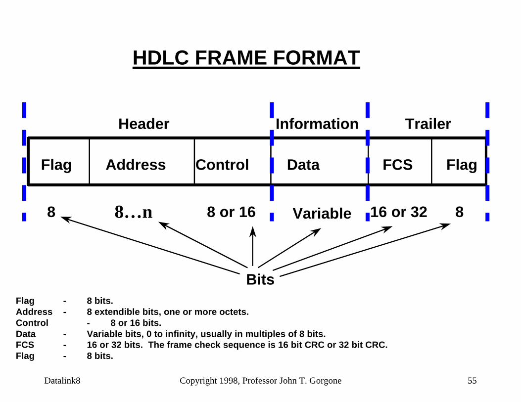
HDLC FRAME FORMAT
Flag Address Control Data FCS Flag
Header Information Trailer
8 8 or 16 Variable 816 or 32
BitsFlag - 8 bits.Address - 8 extendible bits, one or more octets.Control - 8 or 16 bits.Data - Variable bits, 0 to infinity, usually in multiples of 8 bits.FCS - 16 or 32 bits. The frame check sequence is 16 bit CRC or 32 bit CRC.Flag - 8 bits.
8…n

Datalink8 Copyright 1998, Professor John T. Gorgone 56
ADDRESS FIELD
Normal - 8 bits long.
Extended - address length in multiples of seven bits.
All-stations address.
All 1s = Primary sending to all secondary stations.
1st bit
8 bits
1st bit
- - - - - - - -
1 1 1 1 1 1 1 1
1 = Last Octet ofaddress field
0 = Count Octet as partof address field
0 0 07 Bits 7 Bits 7 Bits

Datalink8 Copyright 1998, Professor John T. Gorgone 57
Three Types of HDLC Frames
n Information Frame or I-Frame
n Supervisory Frame or S-Frame
n Unnumbered Frame or U-Frame
n Identification of the frame is determined in the Control Field.

Datalink8 Copyright 1998, Professor John T. Gorgone 58
CONTROL FIELD
I: Information
S: Supervisory
U: Unnumbered
3-Frame Types1 2 3 4 5 6 7 8
0
1
11
0
N(S)
S
M M
N(R)
N(R)
P/F
P/F
P/F
N(S) = Send sequence numberN(R) = Receive sequence numberS = Supervisory function bitsM = Unnumbered function bitsP/F = Poll/final bitP = Poll (primary)F = Final (secondary)

Datalink8 Copyright 1998, Professor John T. Gorgone 59
CONTROL FIELD FORMAT
1 2 3 4 5 6 7 80
1
1 1
0
N (S)
S
M
P/F
P/F
P/F
N (R)
N (R)
M
3 TypesI: Information (User Data)
S: Supervisory
U: Unnumbered
Identify frame types
N(S) = Send sequence numberN(R) = Receive sequence numberS = Supervisory function bitsM = Unnumbered function bitsP/F = Poll/final bitP = Poll (Primary)F = Final (secondary)
Datalink8 Copyright 1998, Professor John T. Gorgone 60
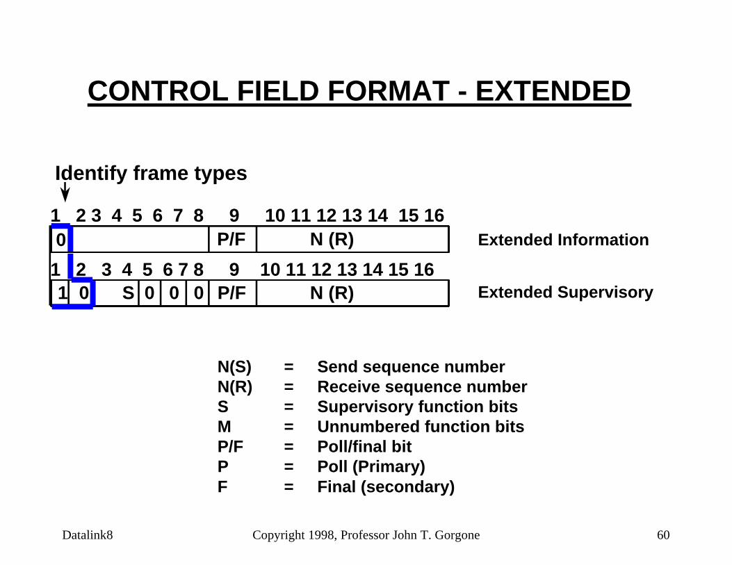
CONTROL FIELD FORMAT - EXTENDED
1 2 3 4 5 6 7 8 9 10 11 12 13 14 15 16
1 2 3 4 5 6 7 8 9 10 11 12 13 14 15 16
Identify frame types
0
1 0 0 0 0S P/F
P/F
N (R)
N (R) Extended Information
Extended Supervisory
N(S) = Send sequence numberN(R) = Receive sequence numberS = Supervisory function bitsM = Unnumbered function bitsP/F = Poll/final bitP = Poll (Primary)F = Final (secondary)

Datalink8 Copyright 1998, Professor John T. Gorgone 61
Flag Fields: BIT STUFFING
Flag Pattern: 01111110 - Unique Pattern- Used to Syn
Original Stream:
. . . 111111111111011111101111110. . .Transmitter will insert an extra 0 bit after sending five 1's (except for flag fields)
HDLC allows arbitrary bit patterns. So, the flag pattern may appear inside a frame, thus destroying frame-levelsynchronization. To avoid this problem, bit stuffing is used.

Datalink8 Copyright 1998, Professor John T. Gorgone 62
BIT STUFFING (Continued)
After Bit-Stuffing: Inserted extra 0 bit
. . .11111011111011011111010111110. . . .
Receiver detects 5 1's and examines 6th bitIf 6th bit = 0 then delete,If 6th bit = 1 and 7th bit = 0 then a flag,If 6th bit = 1 and 7th bit = 1 then send abort condition
With the use of bit stuffing, arbitrary bit patterns can be used in the data field--this is known as data transparency.

Datalink8 Copyright 1998, Professor John T. Gorgone 63
Examples
Flag Flag
Flag FlagFlag
Flag Flag
Flag FlagFlag
(a) An inverted bit splits a frame in two
(b) An inverted bit merges two frames
Transmitted frame
bit inverted
received frame
Transmitted frame
bit inverted
received frame
Two pitfalls of bit stuffing

HDLC COMMANDS AND RESPONSES
NAME FUNCTION DESCRIPTION
Information (I) C/R Exchange user dataSupervisory (S)
Receive Ready (RR) C/R Positive acknowledgment; ready to receive I-frameReceive Not Ready (RNR) C/R Positive acknowledgment; not ready to receive
Reject (REJ) C/R Negative acknowledgment; go back NSelective Reject (SREJ) C/R Negative acknowledgment; selective repeat
Unnumbered (U)Set Normal Response/
Extended mode (SNRM/SNRME)C Set mode; extended = two octet control field
Set Asynchronous Response/Extended mode (SARM/SARME)
C Set mode; extended = two octet control field
Set Asynchronous Balanced/Extended Mode (SABM/SABME)
C Set mode; extended = two octet control field
Set Initialization Mode (SIM) C Initialize link control functions in addressed stationDisconnect (DISC) C Terminate logical link connection
Unnumbered Acknowledgment (UA) R Acknowledges acceptance of one of the above set-mode commands
Disconnected Mode (DM) R Secondary is logically disconnectedRequest Disconnect (RD) R Request for DISC command
Request Initialization Mode (RIM) R Initialization needed; request for SIM commandUnnumbered Information (UI) C/R Used to exchange control information
Unnumbered Poll (UP) C Used to solicit control informationReset (RSET) C Used for recovery; resets N(R), N(S)
Exchange Identification (XID) C/R Used to request/report identity and statusTest (TEST) C/R Exchange identical information fields for testing
Frame Reject (FRMR) R Reports receipt of unacceptable frame

Datalink8 Copyright 1998, Professor John T. Gorgone 65
TABLE 2HDLC Command/Response Repertoire
FormatControl Field
Bit Encoding**1 2 3 4 5 6 7 8
Commands Responses
0 - N(S) - * - N(R) - I - Information
1 0 0 0 * - N(R) -1 0 0 1 * - N(R) -1 0 1 0 * - N(R) -1 0 1 1 * - N(R) -
RR - Receive ReadyREJ - RejectRNR - Receive Not ReadySREJ - Selective Reject
1 1 0 0 * 0 0 0 1 1 0 0 * 0 0 11 1 0 0 * 0 1 01 1 0 0 * 1 0 01 1 0 0 * 1 1 01 1 0 0 * 1 1 11 1 0 1 * 0 0 0 1 1 0 1 * 0 0 11 1 0 1 * 0 1 01 1 0 1 * 0 1 11 1 1 0 * 0 0 01 1 1 0 * 0 0 11 1 1 1 * 0 0 01 1 1 1 * 0 0 11 1 1 1 * 0 1 01 1 1 1 * 0 1 11 1 1 1 * 1 0 01 1 1 1 * 1 0 11 1 1 1 * 1 1 0
UI - Unnumbered Information
RD - Request Disconnect
UA - Unnumbered AcknowledgeTEST - Data Link TestNon Reserved 0Non Reserved 1Non Reserved 2Non Reserved 3RIM Request Initialization ModeFRMR - Frame RejectDM - DISC. Mode
XID - Exchange Identification
NOTE: - * Bit 5 represents the position of the poll/final bit.** The bit order is shown as presented in the text of HDLC.
Bit 1 is the low-order bit and is transmitted first.
Unnumbered
Supervisory
Information I - Information
UI - Unnumbered InformationSNRM - Set Normal Response ModeDISC - DisconnectUP - Unnumbered Poll
TEST - Data Link TestNon Reserved 0Non Reserved 1Non Reserved 2Non Reserved 3SIM - Set Initialization Mode
SARM - Set ASYNC Response ModeRSET - ResetSARME - Set Arm Extended ModeSNRME - Set NRM Extended ModeSABM - Set ASYNC Balanced ModeXID - Exchange IdentificationSABME - Set ABM Extended Mode
RR - Receive ReadyREJ - RejectRNR - Receive Not ReadySREJ - Selective Reject

Datalink8 Copyright 1998, Professor John T. Gorgone 66
PIGGYBACKING OR ACKNOWLEDGMENTS
Station A
4 FramesTransmitted
No Frames Received
Station B
3 FramesTransmitted
2 Frames Received
Ns=4
Nr=1
Ns=3
Nr=1
Fr.4 Fr.3
Nr=3
Ns=1
Nr=3
Ns=3
Nr=3
Ns=2
Fr.1 Fr.3Fr.2

Datalink8 Copyright 1998, Professor John T. Gorgone 67
PIGGYBACKED ACKNOWLEDGMENT
0,0
1,0
2,0
3,0
4,1
5,2
6,2
7,2 2,7
0,3
1,4
N(S),N(R)
All Information Frames

Datalink8 Copyright 1998, Professor John T. Gorgone 68
SUPERVISORY FRAMES (S-FRAME)
1. Receive Ready = Positive acknowledgment (RR)
2. Receive Not Ready = Positive acknowledgment (RNR) and Send no more I-frames until subsequent RR is sent
3. Reject = Go-Back-N ARQ (REJ)
4. Selective Reject = Selective-repeat ARQ (SREJ)
S-Frame is used for Flow and Error Control:

Datalink8 Copyright 1998, Professor John T. Gorgone 69
UNNUMBERED FRAMES
1. Mode-setting Commands and Responses
2. Information transfer Commands and Responses
3. Recovery Commands and Responses
4. Miscellaneous Command and Responses

Datalink8 Copyright 1998, Professor John T. Gorgone 70
LINK SETUP AND DISCONNECT EXAMPLE
B,SABME
B,SABME,P
A,UA,F
Data Transfer
A,UA
B,DISC
Station A Station B
T.O.

Datalink8 Copyright 1998, Professor John T. Gorgone 71
TWO WAY DATA EXCHANGE EXAMPLE
B,1,0,0Station A Station B
A,1,0,1
B,1,1,1
B,1,2,1
A,1,1,3
B,1,3,2
A,1,2,4
B,RR,4
A,1,3,4

Datalink8 Copyright 1998, Professor John T. Gorgone 72
BUSY CONDITION EXAMPLE
Station A Station BA,1,4,0
B,RNR,4
A,RR,0,P
B,RNR,4,F
B,RR,4
A,1,4,0
Datalink8 Copyright 1998, Professor John T. Gorgone 73
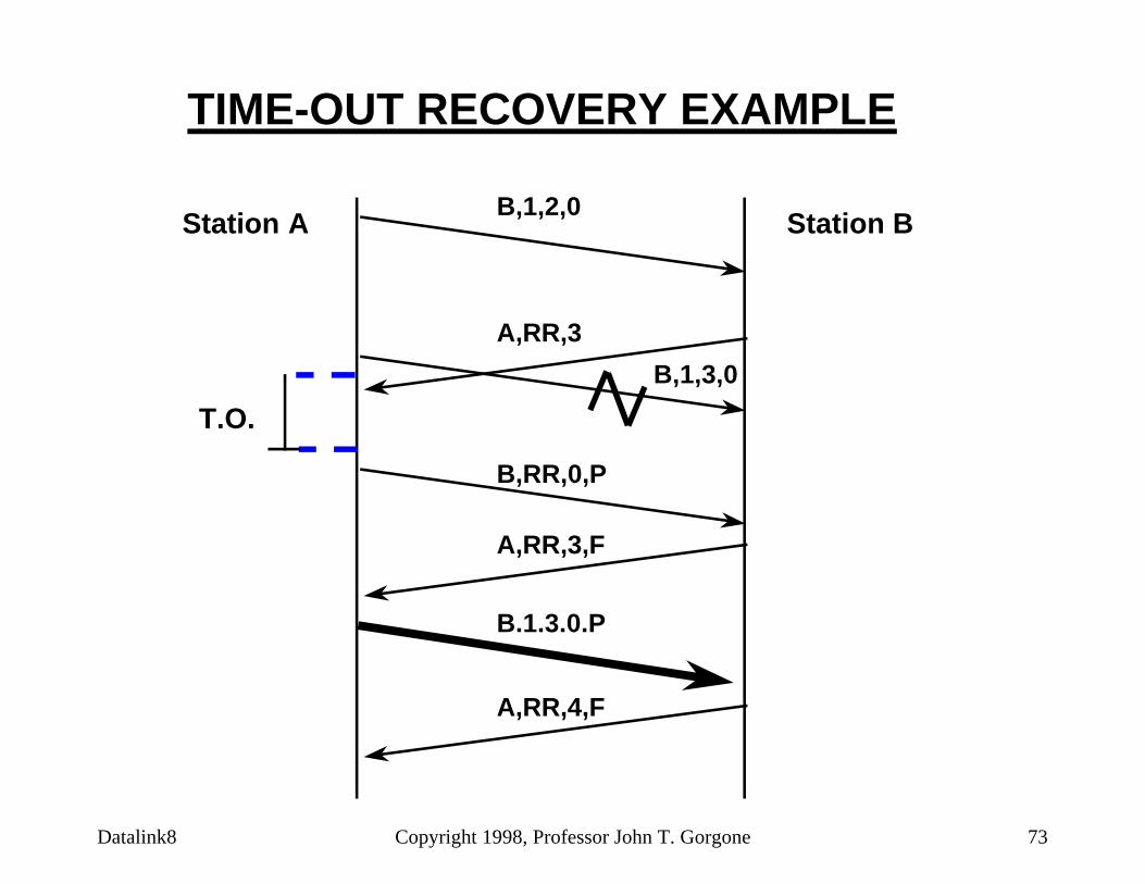
TIME-OUT RECOVERY EXAMPLE
Station A Station BB,1,2,0
A,RR,3
B,1,3,0
B,RR,0,P
A,RR,3,F
B.1.3.0.P
T.O.
A,RR,4,F

Datalink8 Copyright 1998, Professor John T. Gorgone 74
KEY
SABM = Set Asynchronous Balanced Mode
UA = Unnumbered Acknowledge
DISC = DISConnect

Datalink8 Copyright 1998, Professor John T. Gorgone 75
HDLC MODES (DATA TRANSFER MODES)
n Normal Response Mode (NRM)– Unbalanced configuration– Primary initiates all exchanges (Polling and Selecting)– Used on Multipoint lines and Point-to-Point links (host to terminal)
n Asynchronous Balanced Mode (ABM)– Combined stations– Balanced configurations– Full-Duplex Point-to-Point links
n Asynchronous Response Mode (ARM)– Secondary may initiate an exchange (Hub Polling, Other)– Primary responsibility for link maintenance

Datalink8 Copyright 1998, Professor John T. Gorgone 76
LAYER INTERACTIONS PROTOCOL ACTIONS LAYER INTERACTIONS
System A
Network LinkLayer Layer
System B
Link Network Layer Layer
Connect Request
Connect Confirm
Data Request
Data Confirm
Disconnect Request
Disconnect Confirm
SABM
UA
Information Frame (s)
Acknowledge Frame (s)
DISC
UA
Connect Indicate
Data Indicate
Disconnect Indicate
EXAMPLE

Datalink8 Copyright 1998, Professor John T. Gorgone 77
SYSTEM ASYSTEM B
Data Message
EOT
ENQ
ACK0
Wish to Send
Okay
ACK0
Data Message
ACK1
Received OK
AcknowledgeData Message
ACK0
Received OK
AcknowledgeData Message
WACK
Received OK but not ready next msge
Acknowledge wit waitENQ
WACK
Received OK still busy
Acknowledge wit waitENQ
ACK1
Received OK
Okay to send
Received OK
AcknowledgeFinished transmitting
EXAMPLE

Datalink8 Copyright 1998, Professor John T. Gorgone 78
Typical Message Traffic Controlled by Data Link Control Protocol
Computer System 1 Computer System 2
Hello, I wish to connectSTARTUP
ACK
OkayENQI wish to send data
Okay
ACK
Data Message 1Sending first message
ACK
Data Message 2 It is okay
*Sending second message
NAK
Second message had CRC errorData Message 2Sending second message again
ACK
Your message was not correctEOT
I am finished transmittingACK
OkayACK
ACK
Data Message 1 I am here, too
I am here

Datalink8 Copyright 1998, Professor John T. Gorgone 79
Feature Comparison of Data Link Control Procedures
Feature BSC (IBM) DDCMP (DEC) HDLCTransmission Technique
Async/sync Async/sync Sync
Transmission Mode Half duplex Half/full duplex Half/full duplex
FramingStartStop
SYNSYNCharacters
SYNSYNCount
FlagFlag
Frame Formats Numerous 1 (three types) 1 (three types)Control Information Header, control
framesHeader (8 bytes) Header (1-2
bytes)Addressing Contention or polling Header HeaderError Detection LRC, CRC-16, CR-12 CRC-16 CRC-CCITTError Checking Transmission block
onlyHeader and data field
Entire frame
Error Control Stop and wait Go-Back-N Go-Back-N or selective repeat
Flow Control WACK Sliding window Sliding windowWindow Size 1 255 7 or 127Transparency DLE Count Bit stuffing
Character-Oriented Link Control
Top Related