


Languages
Pages
Legal

__________________________________________________________________________
- 1 -
MAXBE
Interoperable monitoring, diagnosis and maintenance
strategies for axle bearings – MAXBE
Integrating and strengthening the European Area
Co-operative Research Projects
Deliverable 2.3: Identification of samples and
available rolling stock for testing
Issue no. 0.2
Start date of project: 2012-11-01 Duration: 36 months
Organisation name of lead contractor for this deliverable: EMEF, SA
__________________________________________________________________________
- 2 -
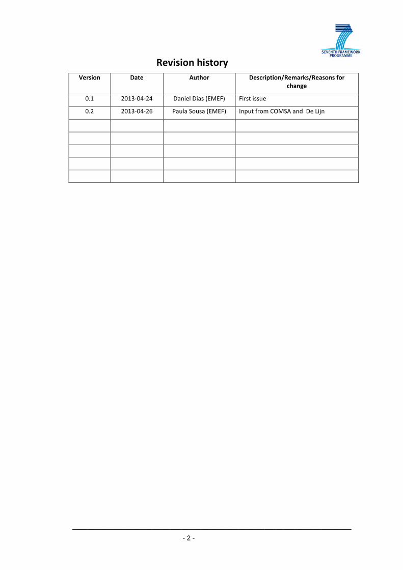
Revision history
Version Date Author Description/Remarks/Reasons for
change
0.1 2013-04-24 Daniel Dias (EMEF) First issue
0.2 2013-04-26 Paula Sousa (EMEF) Input from COMSA and De Lijn

__________________________________________________________________________
- 3 -
1. INTRODUCTION
The current document presents the rolling stock for the trials and validation of the MAXBE
systems. The document provides technical information about the rolling stock. General
description about the vehicle and the kind of commercial service and mechanical and
electrical information is provided.

__________________________________________________________________________
- 4 -
2. AVAILABLE ROLLING STOCK AND SAMPLES
2.1. ELECTRIC MULTIPLE UNIT – EMU 3400
• General Description
The Electric Multiple Unit – EMU 3400 is used for urban transportation in the north of
Portugal. The railway urban service from Oporto to the cities of Braga and Guimarães (to the
north) and from Oporto to Aveiro (to the south), is provided by thirty four railcars of EMU
3400 type. The UME operation is managed by the Portuguese Railways, CP – Porto, and
started its commercial service in 2002.
This electrical railcar is formed by four articulated vehicles as can be seen in Figure 1. The
railcar and its bogies were developed for the standard Iberian track gauge of 1668 mm and a
maximum speed of 140 km/h.
Electric energy is used by railcar traction. The electric energy is obtained from the 25 kV AC
50 Hz infrastructure catenary through pantograph installed in one of the vehicles. The EMU
has six three-phase asynchronous motors delivering a maximum output at the wheel of 1400
kW.
Figure 1 – EMU Train configuration

__________________________________________________________________________
- 5 -
• Mechanical and Electrical Characteristics
The railcar has two different power supplies available: 230 VAC and 110 VDC. The first one,
230 VAC, is directly dependent of the main circuit of the power supply system. This tension
is achieved from the catenary (25 kV). The second one, 110 VDC, is from the auxiliary circuit
of the power supply system. This tension is obtained from the batteries installed in the
railcar which are charged by the charger integrated in the auxiliary converters. The 110 VDC
can vary between +25% and -30%.
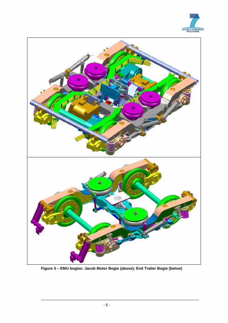
The railcar is composed by five bogies, being the three central ones motor bogies while the
remaining two being trailer bogies. The motor bogies are Jacobs type and each one supports
two carbodies on its four airsprings suspension system. The trailer bogies are conventional
end trailer bogies and together with the Jacobs bogies support each carbody end. In the
Figure 3 two types of bogies are presented.
Figure 2 – Electric Multiple Unit 3400
__________________________________________________________________________
- 6 -
Figure 3 – EMU bogies: Jacob Motor Bogie (above); End Trailer Bogie (below)
__________________________________________________________________________
- 7 -
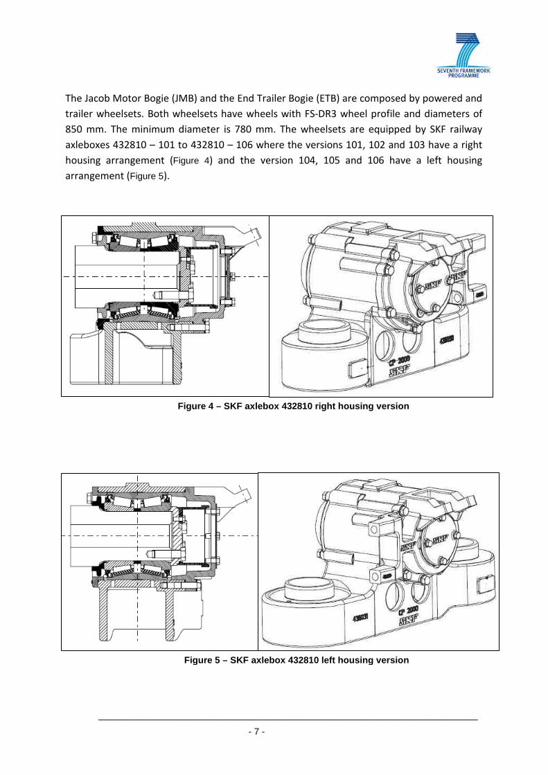
The Jacob Motor Bogie (JMB) and the End Trailer Bogie (ETB) are composed by powered and
trailer wheelsets. Both wheelsets have wheels with FS-DR3 wheel profile and diameters of
850 mm. The minimum diameter is 780 mm. The wheelsets are equipped by SKF railway
axleboxes 432810 – 101 to 432810 – 106 where the versions 101, 102 and 103 have a right
housing arrangement (Figure 4) and the version 104, 105 and 106 have a left housing
arrangement (Figure 5).
Figure 4 – SKF axlebox 432810 right housing version
Figure 5 – SKF axlebox 432810 left housing version
__________________________________________________________________________
- 8 -
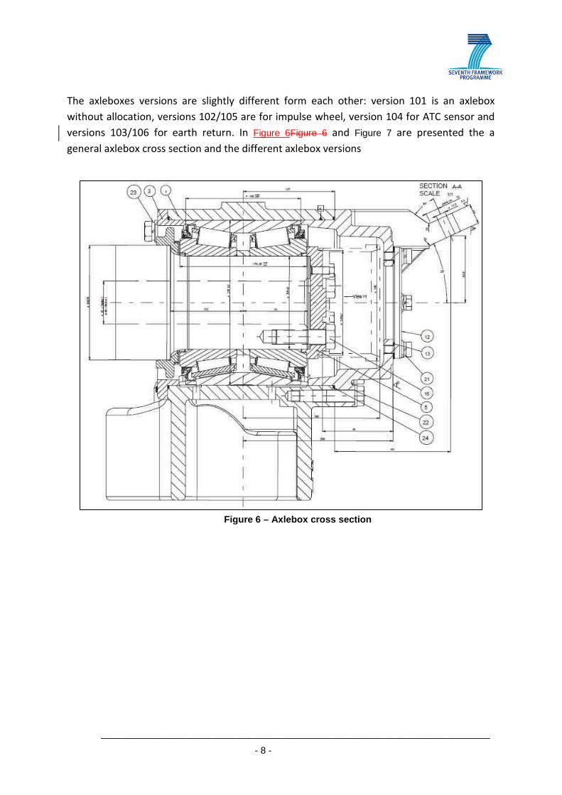
The axleboxes versions are slightly different form each other: version 101 is an axlebox
without allocation, versions 102/105 are for impulse wheel, version 104 for ATC sensor and
versions 103/106 for earth return. In Figure 6Figure 6 and Figure 7 are presented the a
general axlebox cross section and the different axlebox versions
Figure 6 – Axlebox cross section

__________________________________________________________________________
- 9 -
Figure 7 – Different axlebox versions

__________________________________________________________________________
- 10 -
The SKF railway axleboxes include a tapered bearing unit (TBU) 130 x 230 x 160 mounted
direct on the cylindrical axle journal. In Figure 8 is represented the TBU components.
The SKF tapered bearing BT2-7088 is lubricated with Shell GadusRail S3 EUFR (previous
name Shell Alvania Grease 2760B). The main characteristics are indicated in table Table 1.
Table 1 – Shell GadusRail S3 EUFR characteristics
Shell GadusRail Grease S3 EUFR
NLGI Consistency 2.5
Colour Ligth brown
Soap Type Lithium
Base Oil (type) Mineral
Kinematic Viscosity
@ 40ºC cSt
@ 100ºC cSt
(IP 71/ASTM-D445)
100
11
Dropping Point °C
(IP 322/ASTM-D566-76)
180
one Penetration
Unworked @ 25°C 0.1 mm
(IP 50/ASTM-D217)
225
Figure 8 – TBU components: 1 – distance ring; 2 – distance ring; 3 – internal part Z labyrinth; 4 –external part Z labyr inth; 5 – BT2-7088
Bearing; 6 – distance ring
__________________________________________________________________________
- 11 -
2.2. ELECTRIC MULTIPLE UNIT 3150/3250: ELECTRIC TRIPLE UNIT – ETU 3150 AND ELECTRIC
QUADRUPLE UNIT – EQU 3250
• General Description
The Electric Multiple Unit – EMU 3150/3250 is composed by two railcars, the Electric Triple
Unit 3150 and the Electric Quadruple Unit 3250. The 3150/3250 railcar is used for urban
transportation in Lisbon metropolitan area. The commercial service connects the railway
station of Cais-do-Sodré, Lisbon district, to Cascais railway station, Cascais district. The
operation is managed by the Portuguese Railway, CP – Lisbon. The 3150/3250 was
refurbished during the 90’s and re-started the commercial service in 2001.
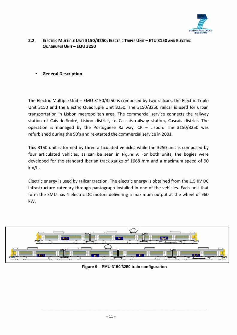
This 3150 unit is formed by three articulated vehicles while the 3250 unit is composed by
four articulated vehicles, as can be seen in Figure 9. For both units, the bogies were
developed for the standard Iberian track gauge of 1668 mm and a maximum speed of 90
km/h.
Electric energy is used by railcar traction. The electric energy is obtained from the 1.5 KV DC
infrastructure catenary through pantograph installed in one of the vehicles. Each unit that
form the EMU has 4 electric DC motors delivering a maximum output at the wheel of 960
kW.
Figure 9 – EMU 3150/3250 train configuration

__________________________________________________________________________
- 12 -
• Mechanical and Electrical Characteristics
The railcar has two different power supplies available: 230 VAC and 96 VDC. The first one,
230 VAC, is converted from the primary source of energy (catenary 1.5 KV DC). The second
one, 96 VDC, is from the auxiliary circuit of the power supply system. This tension is
obtained from the batteries installed in the railcar which are charged by the charger
integrated in the auxiliary converters.
The 3150 railcar is composed by six bogies while the 3250 railcar is composed by eight
bogies. In both cases, there are two powered bogies, located in the motor vehicle - Figure 9,
being the remaining ones trailer bogies. There are five types of bogies which are used in
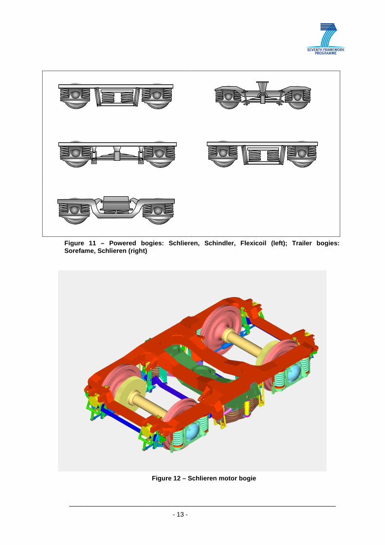
both railcars: powered bogies Schlieren, Schindler, Flexicoil and trailer bogies Sorefame,
Schlieren. The bogie types can be observed in Figure 11 and image of a Schlieren motor bogie
is presented Figure 12.
Figure 10 – Electric Multiple Unit 3150/3250
__________________________________________________________________________
- 13 -
Figure 11 – Powered bogies: Schlieren, Schindler, Flexicoil (left); Trailer bogies: Sorefame, Schlieren (right)
Figure 12 – Schlieren motor bogie
__________________________________________________________________________
- 14 -
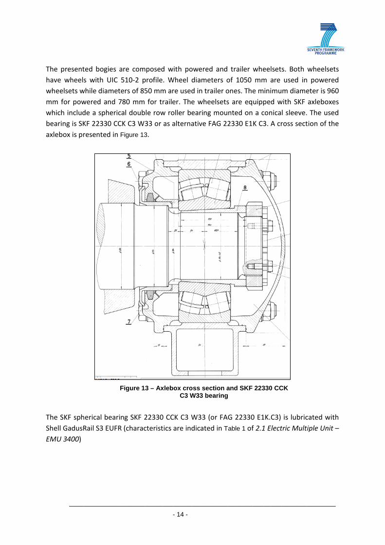
The presented bogies are composed with powered and trailer wheelsets. Both wheelsets
have wheels with UIC 510-2 profile. Wheel diameters of 1050 mm are used in powered
wheelsets while diameters of 850 mm are used in trailer ones. The minimum diameter is 960
mm for powered and 780 mm for trailer. The wheelsets are equipped with SKF axleboxes
which include a spherical double row roller bearing mounted on a conical sleeve. The used
bearing is SKF 22330 CCK C3 W33 or as alternative FAG 22330 E1K C3. A cross section of the
axlebox is presented in Figure 13.
The SKF spherical bearing SKF 22330 CCK C3 W33 (or FAG 22330 E1K.C3) is lubricated with
Shell GadusRail S3 EUFR (characteristics are indicated in Table 1 of 2.1 Electric Multiple Unit –
EMU 3400)
Figure 13 – Axlebox cross section and SKF 22330 CCK C3 W33 bearing

__________________________________________________________________________
- 15 -
2.3. PENDULINO – CPA 4000
• General Description
Pendulino is used for passenger long distance transportation. The railway service is provided
by ten railcars and connects the cities of Braga (north) to Faro (south) passing by the main
cities of Oporto, Aveiro, Coimbra and Lisbon. The pendulino is managed by the Portuguese
Railways, CP – Regional / Long Distance, and started its commercial service in 1999.
This electrical railcar is a tilting train and is formed by six vehicles as can be seen in Figure 14.
The railcar and its bogies were developed for the standard Iberian track gauge of 1668 mm
and a maximum speed of 220 km/h.
Electric energy is used by railcar traction. The electric energy is obtained from the 25 kV AC
50 Hz infrastructure catenary through pantograph installed in one of the vehicles. The
electric traction is carried out by eight electric motors which can deliver a 4000 kW as a
maximum output on the wheels.
Figure 14 – Pendulino Train configuration
__________________________________________________________________________
- 16 -
• Mechanical and Electrical Characteristics
The railcar has two different power supplies available: 230 VAC and 110 VDC. The first one,
230 VAC, is directly dependent of the main circuit of the power supply system. This tension
is achieved from the catenary (25 kV). The second one, 110 VDC, is from the auxiliary circuit
of the power supply system. This tension is obtained from the batteries installed in the
railcar which are charged by the charger integrated in the auxiliary converters.
The pendulino is formed by twelve bogies being eight of them motor ones. The four trailer
bogies are located in the two middle vehicles of the railcar. All bogies have two levels of
vertical and transversal suspension. In addition, all bogies also have a lateral active
suspension and hydraulic actuators to perform tilting. In Figure 16 and Figure 17 motor and
trailer bogies are presented.
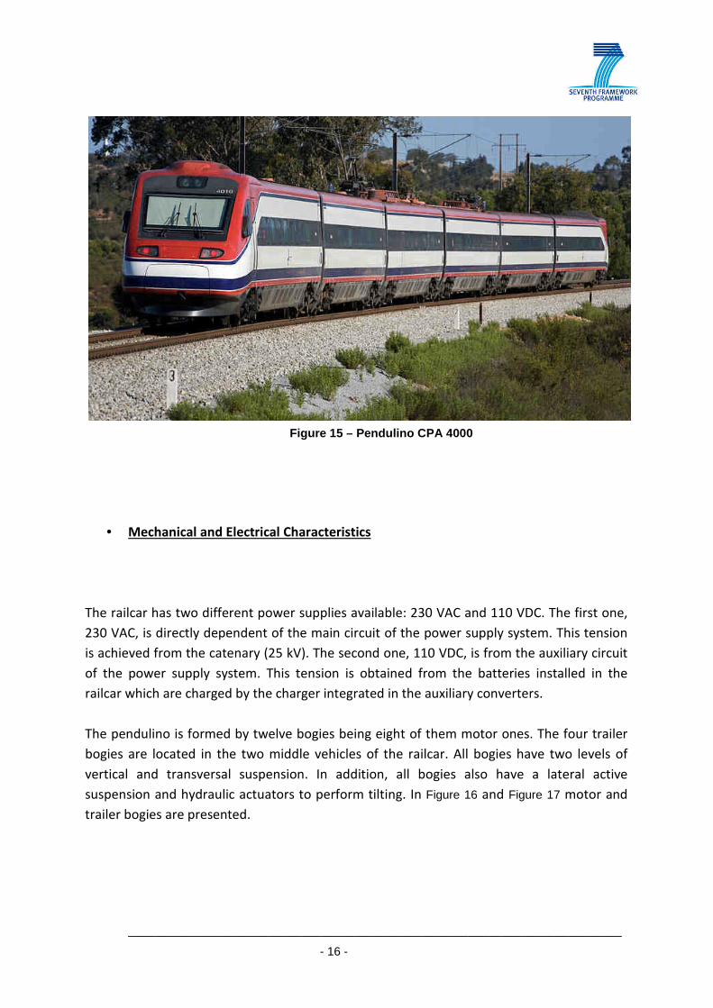
Figure 15 – Pendulino CPA 4000

__________________________________________________________________________
- 17 -
Figure 16 – Pendulino motor bogie

__________________________________________________________________________
- 18 -
Figure 17 – Pendulino trailer bogie
__________________________________________________________________________
- 19 -
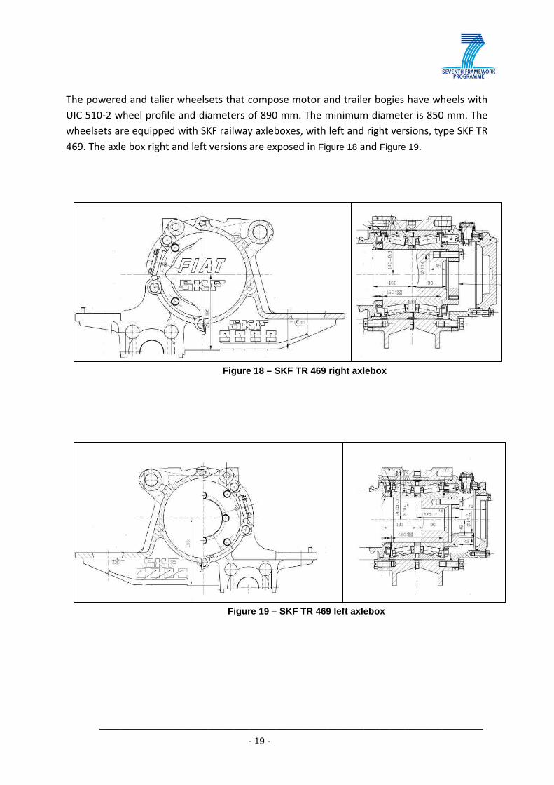
The powered and talier wheelsets that compose motor and trailer bogies have wheels with
UIC 510-2 wheel profile and diameters of 890 mm. The minimum diameter is 850 mm. The
wheelsets are equipped with SKF railway axleboxes, with left and right versions, type SKF TR
469. The axle box right and left versions are exposed in Figure 18 and Figure 19.
Figure 18 – SKF TR 469 right axlebox
Figure 19 – SKF TR 469 left axlebox
__________________________________________________________________________
- 20 -
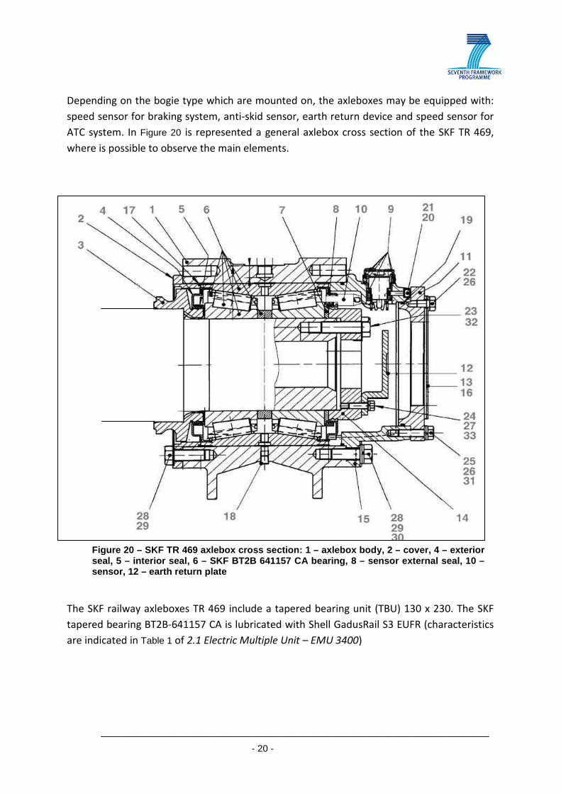
Depending on the bogie type which are mounted on, the axleboxes may be equipped with:
speed sensor for braking system, anti-skid sensor, earth return device and speed sensor for
ATC system. In Figure 20 is represented a general axlebox cross section of the SKF TR 469,
where is possible to observe the main elements.
The SKF railway axleboxes TR 469 include a tapered bearing unit (TBU) 130 x 230. The SKF
tapered bearing BT2B-641157 CA is lubricated with Shell GadusRail S3 EUFR (characteristics
are indicated in Table 1 of 2.1 Electric Multiple Unit – EMU 3400)
Figure 20 – SKF TR 469 axlebox cross section: 1 – axlebox body, 2 – cover, 4 – exterior seal, 5 – interior seal, 6 – SKF BT2B 641157 CA bea ring, 8 – sensor external seal, 10 –sensor, 12 – earth return plate

__________________________________________________________________________
- 21 -
2.4. EURO4000 LOCOMOTIVE
• General Description
The freight trains of COMSA Rail Transport that are used to transport goods between Spain
and Portugal are pulled by Euro4000 diesel locomotives, manufactured by Vossloh and EMD
(Electro-Motive Diesel Inc). The Euro4000 locomotives owned by COMSA Rail Transport
comply with the Spanish and Portuguese requirements, and hence, they can operate in both
Spain and Portugal indistinctively. The main type of goods transported by these trains are
wood and components for the iron and steel industry, with a total hauled weight up to
1.100-1.200 tones per train.
With a total of 5 Euro4000 locomotives, COMSA Rail Transports undertakes the following
services between Spain and Portugal:
Lugo (Spain) -Louriçal (Portugal): [5 trains per week RT/ 10 journeys]
A Coruña (Spain) -Louriçal (Portugal): [5 trains per week RT/ 10 journeys]
Lalin (Spain) -Louriçal (Portugal): [2 trains per week RT/ 4 journeys]
Pontevedra (Spain)- via Entroncamento – Sevilla (Spain): [1 train per week RT/ 2 journeys]
Pontevedra (Spain) –via Pampilhosa - Sagunto (Spain) [2 train per week RT/ 4 journeys]
Vigo (Spain) - Entroncamento (Portugal): [1 train per week RT/ 2 journeys]
Figure 21 – Euro4000 locomotive in operation. S ource: COMSA Rail Transport

__________________________________________________________________________
- 22 -
The Euro4000 locomotive has a total weight of around 120 t, a maximum
commercial speed of 120 km/h and a maximum axle load of 20,5 t. The outline of the
locomotive is shown below:
• Mechanical and Electrical Characteristics
The Euro4000 locomotive is one of the most powerful diesel-electric locomotive available on
the European market. The EURO 4000 features Co’-Co’ axle configuration and two-cabin
design. EMD's most fuel-efficient turbocharged V-16 two-stroke diesel engine (16-710) with
electronic fuel injection serves to power the locomotive with an 4,250 HP DIN. In
conjunction with the optimum performance of the driveline, the unit is capable of hauling
heavier and longer freight trains, thus increasing operator competitiveness and efficiency.
The diesel engine is manufactured by EMD (Electro-Motive Diesel, Inc) and has the following
properties:
Figure 22 – Dimensions of Euro4000 locomotive. Source: Vossloh
Figure 23 – Characteristics of the diesel engines. Source: Voss loh

__________________________________________________________________________
- 23 -
The bogies are adapted for the 1.668 mm track-gauge, and their main features
are shown in the following table:
In what regards to the electrical transmission and brake equipment, the main information is
shown in the tables presented below:
Figure 24 – Characteristics of the Euro4000 bogies. Source: Vos sloh
Figure 25 – Characteristics of the electrical transmiss ion and brake equipment. Source: Vossloh

__________________________________________________________________________
- 24 -
The axle bearing used in Euro4000 locomotives is manufactured by TIMKEN, namely, HM
133436 – 90952 model. The housing of the axle bearing is made from cast iron. The grease
used in the axle bearing is Timken Premium. The main dimensions of the axlebox is shown in
the figures below.
Figure 26 – TIMKEN axlebox HM 133436 – 90952. Source: Timken
Figure 27 – Scheme of axle provided with axle bearings. Source: EMD, Inc.
__________________________________________________________________________
- 25 -
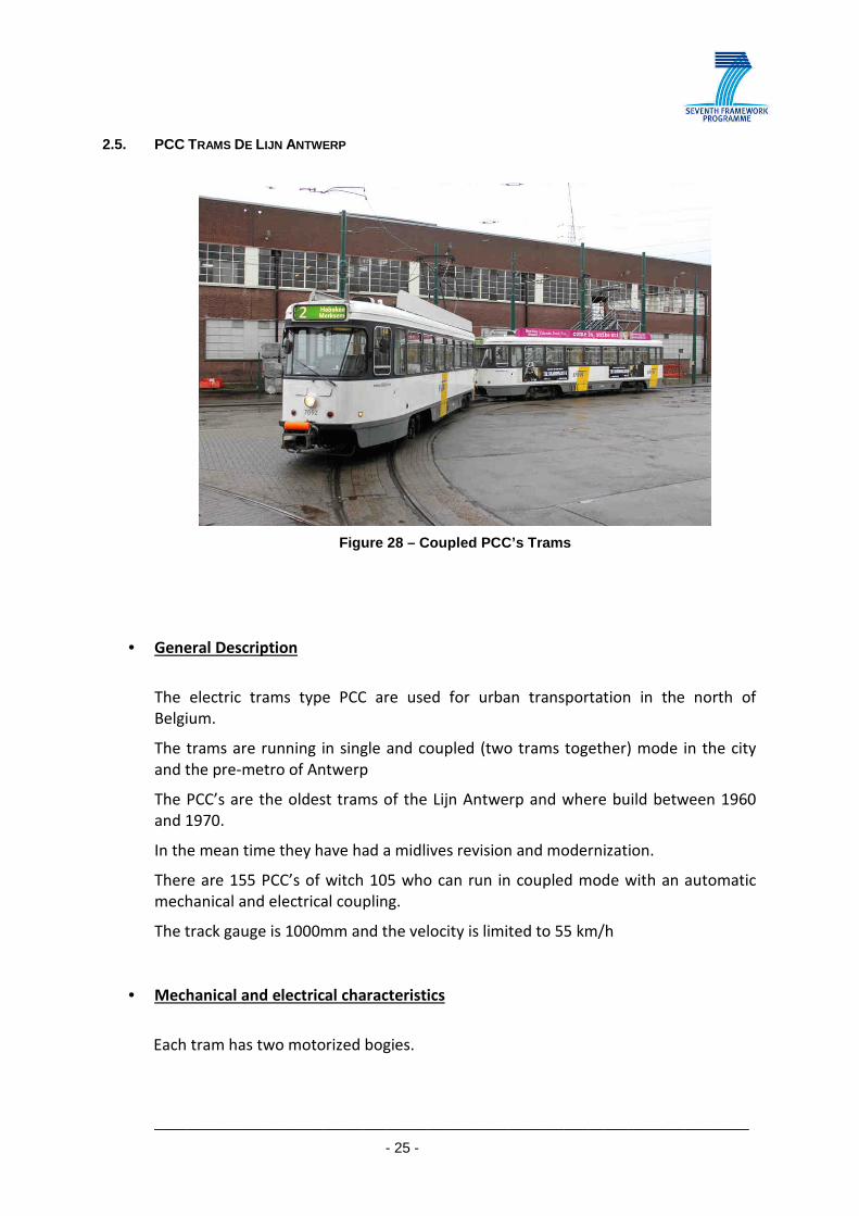
2.5. PCC TRAMS DE LIJN ANTWERP
Figure 28 – Coupled PCC’s Trams
• General Description
The electric trams type PCC are used for urban transportation in the north of
Belgium.
The trams are running in single and coupled (two trams together) mode in the city
and the pre-metro of Antwerp
The PCC’s are the oldest trams of the Lijn Antwerp and where build between 1960
and 1970.
In the mean time they have had a midlives revision and modernization.
There are 155 PCC’s of witch 105 who can run in coupled mode with an automatic
mechanical and electrical coupling.
The track gauge is 1000mm and the velocity is limited to 55 km/h
• Mechanical and electrical characteristics
Each tram has two motorized bogies.

__________________________________________________________________________
- 26 -
The wheel sets have gummy suspended wheels with a maximum
diameter of 660mm and a minimum diameter of 600 mm.
Each axle box has two oil lubricated spherical roller bearings.
The electric energy is obtained from the 600V DC catenaries infrastructure.
The PCC has four DC traction motors of 44KW each.
The traction power supply has been modernized and is generated by GTO or IGBT
power electronic technology.
They can regenerate energy in the catenaries while braking and have anti glide
protection (ABS).
• In the pictures you can see, the drawing of a bogie and the drawing of an axle box
The bearing is 222 19 S MB F2 C3 and lubricated by “Total Carter EP220”

__________________________________________________________________________
- 27 -
3. CONCLUSION
Available samples of new and used bearings together with new and used lubricant will be
provided to the consortium for laboratory tests (Task 2.4 – Laboratory Tests). Also technical
information about the presented rollingstock and bearings will be delivered to the partners
for modelling and analysis (Task 2.5 – Axle bearing modelling and analysis).
The on board systems developed in WP3 – Onboard Systems will be applied in rolling stock
presented in this document. In addition, the wayside systems developed in WP4 – Wayside
Systems will be installed on track sites (both in Portugal and Belgium), defined in Task 2.8 –
Identification of sites for testing, where this specific rollingstock performs commercial
service. The consortium will have access to this rollingstock and track sites in order to
develop, perform test trials and validate MAXBE systems.
Top Related