


Languages
Pages
Legal


7/28/2019 Cumene Design 2520of 2520Equipments
http://slidepdf.com/reader/full/cumene-design-2520of-2520equipments 1/72
6. DESIGN
OF EQUIPMENTS
(A) MAJOR EQUIPMENT
Basis: 1hour of operation
Vapor-pressure data of cumene-Diispropylbenzene:
1/T 103 2.35 2.3 2.25 2.2 2.15 2.10
°C
PA 760 943 1211.9 1480.2 1998.1 2440.6
PB 190.56 257.2 314.1 403.4 518.0 760
LnPA 6.633 6.85 7.1 7.3 7.6 7.8
LnPB
5.25 5.55 5.75 6.0 6.25 6.63
T-xy data for cumene – Diispropylbenzene system :
T °C 152.4 160 170 180 190 202
XA 1 0.733 0.496 0.331 0.163 0
YA 1 0.909 0.791 0.644 0.429 0
Vapour-pressure data from
Perry’s
Chemical Engineers handbook 6th edition pg2-
52
Splitting the feed into two towers of equal capacity as the feed rate of the distillation
tower is too high .The production rate in our case is almost ten times more than thenormal production rate.
Feed: F = 138190.5/2 Kg/hr ;
weight
fraction ;
mole
fractions
= 69095.25 Kg/hrXF = 0.932
XF =
0.948
D = 129051/2 Kg/hr XD = 0.995 XD = 0.996= 64525.5 Kg/hr= 536.8 Kmoles/hr
W = 9139.5/2 Kg/hr XW = 0.01 XW= 0.013
= 4569.5 Kg/hr= 29 Kmoles/hr
[ From material balance equation we find that if XF, XD & XW are kept same , then on
reducing the feed rate to half , both distillate and residue are also reduced to half theiroriginal value .]

7/28/2019 Cumene Design 2520of 2520Equipments
http://slidepdf.com/reader/full/cumene-design-2520of-2520equipments 2/72
Fmolar = (0.932 x 69095.25)/120.19 + (0.068 x 69095.25)/162
= 546.79 Kmols/hr
27

7/28/2019 Cumene Design 2520of 2520Equipments
http://slidepdf.com/reader/full/cumene-design-2520of-2520equipments 3/72
MFeed = 69095/546.8 = 126.5 Kg/kmol
Taking feed as saturated liquid , q=1
Slope of q-line = q/(q-1)= oo
Therefore q-line is vertical.
From the X-Y diagram , XD /(Rm+1) = 0.72Hence Rm =0.38
Assuming a reflux ratio of 1.4 times the Rm value we get
R = 1.4 x 0.38 = 0.532
Now total number of stages including reboiler
= 10
Therefore actual number of stages in the
tower = 9
Number of stages in the enriching section = 3
Number of stages in the stripping section = 6
L = RD =0.532 x 536.8 = 285.6 Kmoles/hr
G = (R+1)D = 1.532 x 536.8 = 822.4
Kmoles/hr
L = L+qF = 285.6 + 1x546.79 = 832.39
Kmoles/hr
G = G+(q-1)F = 822.47+0 = 822.47
Kmoles/hr
Plate Hydraulics :
Enriching Section Stripping Section
Top Bottom Top Bottom
Liquid 285.6 285.6 832.39 832.39
Kgmoles/hr
Vapor 822.47 822.47 822.47 822.47
Kgmoles/hr
X 0.996 0.948 0.948 0.013

7/28/2019 Cumene Design 2520of 2520Equipments
http://slidepdf.com/reader/full/cumene-design-2520of-2520equipments 4/72
Y 0.996 0.97 0.97 0.013
Mavg(Liq) 120.34 122.36 122.36 161.45
Mavg(Gas) 120.34 121.44 121.44 161.45
Liq, Kg/hr 34369.1 34946 101851.2 134389.36
Vap,Kg/hr 98976 99880.75
99880.7
5 132787.7828
Tliquid , oC 152 153 153 202
Tvapour , oC 154 155 155 202
!L , (kg/m3) 746.3 745 745 600
!G ,(kg/m3) 3.436 3.826 3.826 4.072
(L/G)* 0.0235 0.0250 0.0730 0.0830
!G !L)0.5
ENRICHING SECTION
Plate Calculations:
1. Plate spacing ts = 500mm
2. Hole diameter dh =5mm
3. Hole pitch Lp = 3dh = 15mm
4. Tray thickness tT = 0.6dh = 3mm
5. Total hole area
= ( Ah / Ap)Perforated area
= 0.1 for triangular
pitch
6. Plate diameter
From above table , L /G (ρg / ρL) 0.5 = 0.025
From Perry’s handbook 6th edition for ts = 18
inches
Csb flood =0.28
We have,
Unf = Csb(flooding) ( σ /20)0.2 ((ρL -
ρG)/ ρG)0.5
= 0.28(37.3/20)0.2 ((745-3.826) /
3.826)0.5

7/28/2019 Cumene Design 2520of 2520Equipments
http://slidepdf.com/reader/full/cumene-design-2520of-2520equipments 5/72
= 4.41ft/sec
Let us take Un= 0.8 Unf ( %
flooding = 80%)
= 0.8 * 4.41ft/sec
= 1.158 m/sec
te of vapour =99880.75/ (3600*3.826)=7.2
516m3 /
sec
Net area for gas flow, An = volumetric flowrate of vapor/Un
= 7.2516/1.1586
= 6.2589 m2
29
Let
Lw =
0.75
Dc
Lw = Weir Length
Dc = Column Diameter
lumn (Ac ) = π Dc2 = 0.785 Dc
2 4
Sin(θC /2) = (LW /2)/(DC /2) = 0.75
θc= 97.20
Area of down comer (Ad) = πDc
2
θc - Lw DcCos (
θc) 4 360 2 2 2
= (0.212 – 0.1239)
Dc2
= 0.0879 Dc2

7/28/2019 Cumene Design 2520of 2520Equipments
http://slidepdf.com/reader/full/cumene-design-2520of-2520equipments 6/72
Area for gas flow , An = Ac-Ad
= 0.785 Dc2 – 0.0879
Dc2
= 0.6971Dc2
6.2589 = 0.6
911Dc2
Dc =2
.996m
Ac = π /4 DC2
= 0.785 x 2.9962
= 7.046m2
Ad = 0.7889m2
Active area, Aa =Ac –2Ad
= 7.046 – 2(0.7889) =5.468m2
7. Perforated

7/28/2019 Cumene Design 2520of 2520Equipments
http://slidepdf.com/reader/full/cumene-design-2520of-2520equipments 7/72
areaAp:Lw
/ Dc=0.75
where
Lw is
the
wier
length
Lw =
0.75*2.
996 =
2.247m
θc =
97.2 °
α =180 - θc =
180 – 97.2 =
82.8° Peripherywaste = 50mm
= 50*10-3
30
7/28/2019 Cumene Design 2520of 2520Equipments
http://slidepdf.com/reader/full/cumene-design-2520of-2520equipments 8/72
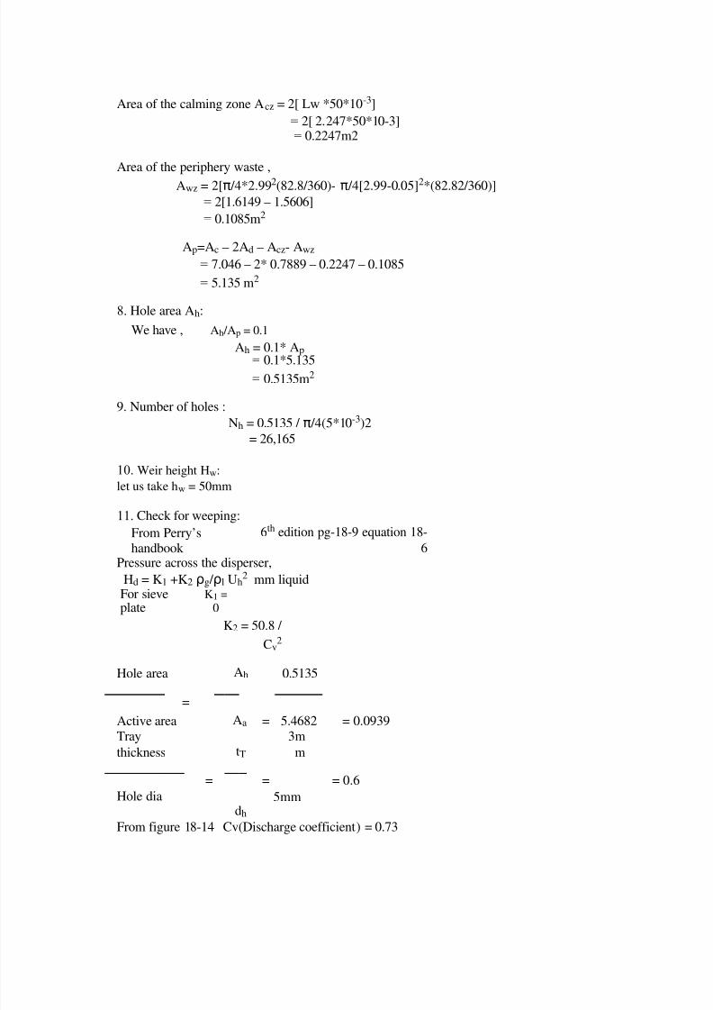
Area of the calming zone Acz = 2[ Lw *50*10-3]
= 2[ 2.247*50*10-3]= 0.2247m2
Area of the periphery waste ,Awz = 2[π /4*2.992(82.8/360)- π /4[2.99-0.05]2*(82.82/360)]
= 2[1.6149 – 1.5606]
= 0.1085m2
Ap=Ac – 2Ad – Acz- Awz
= 7.046 – 2* 0.7889 – 0.2247 – 0.1085
= 5.135 m2
8. Hole area Ah:
We have , Ah /Ap = 0.1
Ah = 0.1* Ap= 0.1*5.135
= 0.5135m2
9. Number of holes :
Nh = 0.5135 / π /4(5*10-3)2
= 26,165
10. Weir height Hw:
let us take hw = 50mm
11. Check for weeping:
From Perry’shandbook
6th edition pg-18-9 equation 18-
6Pressure across the disperser,
Hd = K1 +K2 ρg / ρl Uh2 mm liquid
For sieveplate
K1 =0
K2 = 50.8 /
Cv2
Hole area Ah 0.5135
=
= = 0.0939Active area Aa 5.4682Tray
thickness
=
tT
=
3m
m
= 0.6
Hole diadh
5mm
From figure 18-14 Cv(Discharge coefficient) = 0.73

7/28/2019 Cumene Design 2520of 2520Equipments
http://slidepdf.com/reader/full/cumene-design-2520of-2520equipments 9/72
K2 = 50.8/ (0.73)2 = 95.32
31

7/28/2019 Cumene Design 2520of 2520Equipments
http://slidepdf.com/reader/full/cumene-design-2520of-2520equipments 10/72
Uh = linear velocity of gas through the holes
= volumetric flow rate of vapour / Ah = 7.2516 / 0.5135
= 14.12 m/sec
hd = 0 + 95.32(3.826/745) x14.122
= 97.38 mm liquid
Height of liquid creast over weir ,
how = (664) Fw(q / Lw)2/3
q = vol. flow rate of liquid ,m3 /sec [weeping check is done at the point where
= 34369/(746.3x3600) gas velocity is low]
=0.0127 m3 /sec
q’= volumetric flow rate of liquid in
GPM =0.0127 /(6.309x10-5)
202.76 GPM
Lw = 2.247m = 2.247/0.3048 =7.372 ft
q’/(Lw)2.5 =202.76/(7.372)2.5=1.37
Lw /Dc=2.247/2.996=0.75
Corresponding to this two values Fw=1.02
how = 1.02x664x(0.0127/2.247)2/3
= 21.48 mm liquid
Head loss due to bubble for
mation, hσ = 409(σ / ρLdL)
= 409(37.3/ 746.3x 5)= 4.08mm liq
hd+hσ = 97.38+4.08= 101.47 mm liq
hw + how = 50 +21.48 = 71.48 mm
Ah/Aa = 0.0939, hw+how = 71.48 mm
From fig 18-11, hd K1 PP
Since the value hd K1 LV ZHOO DERYH WKH YDOXH REWDLQHG IURPJUDSK no weeping will occur.
32

7/28/2019 Cumene Design 2520of 2520Equipments
http://slidepdf.com/reader/full/cumene-design-2520of-2520equipments 11/72
12. Check for downcommer flooding:
The downcommer backup is givenby, hdl =ht+hw+how+had+hhg
a. Hydraulic gradient across plate , hhg
For stable operation hd > 2.5hhg For sieve plates hhg is generally small orneiglible Let us take hhg =0 mmliq
b. Total pressure drop across the plate ht:ht = hd + hl’hl’=pressure drop through the aereated liquid = β hds
whereβ =aeration factor to be found from Perry’s fig 18-15
Fga =Ua(ρg)1/2
Ua = 99880/(3600x3.826x5.468)
= 1.326m/sec
ρg = 3.826kg/m3
Fga = Ua !g)1/2
= 1.326 x (3.826)1/2(m/sec) (kg/m3)1/2
= 2.5939/1.2199 (ft/sec)(lb/ft3)1/2
= 2.1263 (ft/sec)(lb/ft3)1/2
From figure, β = 0.6
hds=hw+how+hhg /2
= 50+21.48 + 0
= 71.48mm liq
hl’ = 0.6 * 71.48 = 42.88mm liqht = 97.38 +42.88
= 140.27mm liq
c loss under downcommer area head:
hda = 165.2(q’/Ada)2
let us choose c’ = 1inch=25.4mm hap = hds – c’
= 71.48 – 25.4
= 46.08 mmliq
33

7/28/2019 Cumene Design 2520of 2520Equipments
http://slidepdf.com/reader/full/cumene-design-2520of-2520equipments 12/72
Ada = Lw xhap
=2.247 x46.08x10-
3 =0.1035m2
hda =165.2(0.0127/0.1035)2
=2.4873mmhdc = 140.27 + 50+21.48 +2.4873+0
= 214.23mm
taking ødc= .5
h’dc = hdc /ødc
=214.23/0.5 =
428.46 mm
we have ts= 500 mm
hence ,h’dc < tstherefore no downcommer flooding will occur.
STRIPPING SECTION
Plate Calculations:
5. Plate spacing ts = 500mm
6. Hole diameter dh =5mm
7. Hole pitch Lp = 3dh = 15mm
8. Tray thickness tT = 0.6dh = 3mm
5. Total hole area
= ( Ah / Ap)Perforated area
= 0.1 for triangular pitch
6. Plate diameter
L /G (ρg / ρL) 0.5 = 0.083From above table ,
(maximum at
bottom)
From Perry’s handbook 6th edition for ts = 18 inches
Csb flood = 0.28We have,
Unf = Csb(flooding) ( σ /20)0.2 ((ρL - ρG)/ ρG)0.5
= 0.28(33.41/20)0.2 ((600-4.072) / 4.072)0.5
= 3.75ft/sec
Let us take Un= 0.8 Unf ( % flooding = 80%)
= 0.8 * 3.75ft/sec
= 0.9144 m/sec

7/28/2019 Cumene Design 2520of 2520Equipments
http://slidepdf.com/reader/full/cumene-design-2520of-2520equipments 13/72
34

7/28/2019 Cumene Design 2520of 2520Equipments
http://slidepdf.com/reader/full/cumene-design-2520of-2520equipments 14/72
Volume rate of vapour = 132787.78/(3600*4.072) =
9.058 m3 /sec
Net area for gas flow, An = volumetric flow rate of vapor/Un= 9.058/0.9144
= 9.906 m2
Let
Lw =
0.75
Dc
Lw = Weir Length
Dc = Column Diameter
Area of column (Ac ) = π Dc2 = 0.785
Dc2 4
Sin(θC /2) = (LW /2)/(DC /2) = 0.75
θc= 97.20
Area of down comer (Ad) = π
Dc2
θc - Lw Dc
Cos (
θc) 4 360 2 2 2
= (0.212 – 0.1239) Dc2
= 0.0879 Dc2
Area for gas flow , An = Ac-Ad
= 0.785 Dc2 – 0.0879 Dc2
= 0.6971Dc2
9.906 = 0.6971Dc2 Dc =3.769m
Ac = π /4 DC2
= 0.785 x 3.7692
= 11.15m2
Ad = 0.7889m2
Active area, Aa =Ac –2Ad
= 11.15 – 2(1.248) = 8.654m2

7/28/2019 Cumene Design 2520of 2520Equipments
http://slidepdf.com/reader/full/cumene-design-2520of-2520equipments 15/72
35

7/28/2019 Cumene Design 2520of 2520Equipments
http://slidepdf.com/reader/full/cumene-design-2520of-2520equipments 16/72
7. Perforated areaAp: Lw/Dc = 0.75
where Lw is the wier length
Lw = 0.75*3.769 = 2.827m
θc = 97.2 °
α =180 - θc = 180 – 97.2 = 82.8°
Periphery waste = 50mm = 50*10-3
Area of the calming zone Acz = 2[ Lw *50*10-3]
= 2[ 2.827*50*10-3]= 0.2287m2
Area of the periphery waste ,
Awz = 2[π /4*(3.769)2(82.8/360)- π /4[3.769-
0.05]2*(82.82/360)] = 0.1352m2
Ap=Ac – 2Ad – Acz- Awz
= 11.15 – 2* 1.248 – 0.2287 – 0.1352
= 8.2901 m2
8. Hole area Ah:
We have , Ah /Ap = 0.1
Ah = 0.1* Ap= 0.1*8.2901
= 0.829m2
9. Number of holes :
Nh = 0.829 / π /4(5*10-
3)2 = 42,242
10. Weir height Hw:
let us take hw = 50mm
11. Check for weeping:
From Perry’shandbook
6th edition pg-18-9 equation 18-
6Pressure across the disperser,
Hd = K1 +K2 ρg / ρl Uh2 mm liquid
For sieveplate
K1 =0
K2 = 50.8 /
Cv2
Hole area Ah 0.829
=
Active area Aa 8.654

7/28/2019 Cumene Design 2520of 2520Equipments
http://slidepdf.com/reader/full/cumene-design-2520of-2520equipments 17/72
Tray
thickness
=
tT
=
3m
m
= 0.6
Hole dia dh 5mm
36

7/28/2019 Cumene Design 2520of 2520Equipments
http://slidepdf.com/reader/full/cumene-design-2520of-2520equipments 18/72
From figure 18-14 Cv(Discharge coefficient) = 0.74
K2 = 50.8/ (0.74)2 = 92.74
Uh = linear velocity of gas through the holes= volumetric flow rate of vapour / Ah
= 9.058 / 0.829= 10.92 m/sec
hd = 0 + 92.74(4.072/600) x10.922
= 75.14 mm liquid
Height of liquid creast over weir ,
how = (664) Fw(q / Lw)2/3
q = vol. flow rate of
liquid ,m3 /sec =101851.2/(745x3600)
=0.0379 m3 /sec
[weeping check is done at thepoint where gas velocity islow]
q’= volumetric flow rate of liquid in GPM =0.0379/
(6.309x10⁻⁵)
= 601.93 GPM
Lw = 2.827m = 2.827/0.3048 =9.2749 ft
q’/(Lw)2.5 =601.93/(9.2749)2.5=2.297
Lw /Dc=2.827/3.769=0.75
Corresponding to this two values Fw=1.02
how = 1.02x664x(0.0379/2.827)2/3 = 38.22
mm liquid
Head loss due to bubble formation, hσ =409(σ / ρLdh)
= 409(33.4/ 745x 5)= 3.66mm liq
hd+hσ = 75.14+3.66= 78.81 mm liq hw + how =
50 +38.22 = 88.22 mm
Ah/Aa = 0.1, hw+how = 88.22 mm
From fig 18-11, hd K 1 PP

7/28/2019 Cumene Design 2520of 2520Equipments
http://slidepdf.com/reader/full/cumene-design-2520of-2520equipments 19/72
37

7/28/2019 Cumene Design 2520of 2520Equipments
http://slidepdf.com/reader/full/cumene-design-2520of-2520equipments 20/72
Since the value hd + hσ is well above the value obtained from graph, no weepingwill occur.
12 Check for downcommer flooding:
The downcommer backup is givenby, hdl =ht+hw+how+had+hhg
c. Hydraulic gradient across plate , hhg
For stable operation hd > 2.5hhg
For sieve plates hhg is generally small orneiglible Let us take hhg =0 mmliq
d. Total pressure drop across the plate ht:ht = hd + hl’
hl’=pressure drop through the aereated liquid = β hds
whereβ =aeration factor to be found from Perry’s fig 18-15
Fga =Ua(ρg)1/2
Ua = 132787.78/(3600x4.072x8.654)
= 1.046m/sec
ρg = 4.072kg/m3
Fga = Ua !g)1/2
= 1.046 x (4.072)1/2(m/sec) (kg/m3)1/2
= 1.73 (ft/sec)(lb/ft3)1/2
From figure, β = 0.6
hds=hw+how+hhg /2
= 50+38.22 + 0
= 88.22mm liq
hl’ = 0.6 *88.22 = 52.93mm liq
ht = 75.14 +52.93
= 128.07mm liq
c loss under downcomer area head:
hda = 165.2(q’/Ada)2
let us choose c’ = 1inch=25.4mm hap = hds – c’
= 88.22 – 25.4
= 62.82 mm liquid
38

7/28/2019 Cumene Design 2520of 2520Equipments
http://slidepdf.com/reader/full/cumene-design-2520of-2520equipments 21/72
Ada = Lw xhap
=2.827 x62.82x10-
3 =0.1775m2
hda
=165.2(0.0379/0.1775)2
=7.53mm
hdc = 128.07 + 50+38.22 +7.53+0= 223.82mm
taking ødc= .5
h’dc = hdc /ødc
=223.82/0.5
= 447.64 mm
we have ts= 500 mmhence ,h’dc < ts
therefore no downcommer flooding will occur.
13. Column efficiency:
The efficiency calculations are based on the average conditions prevailing ineach section.
Enriching Section:
Average molar liquid rate = 285.6 Kgmoles/hrAverage mass liquid rate = (34369.1+34969)/2
= 34657.55 Kg/hr
Average molar vapour rate = 822.47 Kgmoles/hr
Average mass vapour rate = (98976+99880.75)/2
= 99428.37 kg/hr
Average density of liquid = (746.3 +745 )/2
= 745.65Kgs/m3 Average density of vapour = (3.436+3.826)/2
= 3.631kgs/hm3
Average temperature of liquid = (152+153)/2 = 152.5°C
Average temperature of vapour = (154+155)/2 = 154.5°C
Viscosity of cumene at 152.5ºC = 0.16cp
Viscosity of DIPB at 152.5ºC = 0.15cpX1=(0.996+0.948)/2 = 0.972
X2 = 1- 0.98 = 0.028
µ av = [x1µ 11/3+x2µ 2
1/3]3
= [0.535+0.0106]3 =0.1626cp

7/28/2019 Cumene Design 2520of 2520Equipments
http://slidepdf.com/reader/full/cumene-design-2520of-2520equipments 22/72
39

7/28/2019 Cumene Design 2520of 2520Equipments
http://slidepdf.com/reader/full/cumene-design-2520of-2520equipments 23/72
Viscosity of cumene vapour at 154.5 C = 0.01cp
Viscosity of DIPB vapour at 154.5 C = 0.011cp
Average vapour composition , y1 = (0.996+0.97)/2 = 0.983 y2= [1-0.983] = 0.017
µ m =∑yiµ iMi1/2 / y∑ iMi1/2
( 0.983x0.01x1201/2 +0.017x0.011x1621/2)
== 0.01cp
(0.983x1201/2 +0.017x1621/2)
Liquid phase diffusivities:
Wilke-chang equation
7.4x10⁻⁸ (ΦMB)0.5 T
DL=
ηBVA0.6
where,
MB= Molecular weight of solvent B = 162Φ=1 for cumene
VA& VB are molar volume of solvent A & B
VA = 16.5x 9 + 1.98x12 = 172.26
VB=16.5x18 + 1.98x22 = 340.56
7.4x10⁻⁸(1x162)0.5x425.5
DL =1.14x 10⁻⁴ cm2 /sec 0.16x(172.26)0.6
Vapour phase diffusivity:
Fuller Etal equation,
10-3xT1.75(1/MA+1/MB)0.5
Dg =
P[∑VA)1/3 ( V∑ B)1/3]2
10-3(273+154.5)1.75(1/120 + 1/162)0.5
Dg =
1x[(172.26)1/3 + (340.56)1/3]2
= 0.0319cm2 /sec
Nscg
= µ g / µ
g Dg
=0.01 x10⁻³ / (3.631 x0.0319 x10-4)
= 0.863

7/28/2019 Cumene Design 2520of 2520Equipments
http://slidepdf.com/reader/full/cumene-design-2520of-2520equipments 24/72
40

7/28/2019 Cumene Design 2520of 2520Equipments
http://slidepdf.com/reader/full/cumene-design-2520of-2520equipments 25/72
Stripping Section:
Average molar liquid rate = 275.34 Kgmoles/hr
Average mass liquid rate = (101851.2+134389.36)/2
= 118120.28 Kg/hr
Average molar vapour rate = 822.47 Kgmoles/hrAverage mass vapour rate = (99880.75+132787.78)/2
= 116334.26 Kgmoles/hr
Average temperature of liquid = (153+202)/2
= 117° C
Average temperature of vapour = (155+202)/2
= 178.5° C
Viscosity of liquid at 177.5 °C= 0.11cp
Viscosity of liquid at 177.5 C = 0.1cp
µ l =[x1µ 11/3 + x2 µ 2
1/3]3
x1=(0.948+0.013)/2 = 0.4805
x2 = 1- 0.4805 = 0.5195
µ l =[0.4805x0.111/3 +0.5195x0.11/3]3
= 0.1071 cp
Viscocity of vapour cumene at 178.5 C= 0.01cpViscosity of vapour DIPB at 178.5 C = 0.0115cp
Y1=(0.97+0.013)/2 = 0.4915Y2 = 1-0.4915 = 0.5085
y∑ iµ iMi1/2
µ v =
y∑ iMi1/2
= (0.0553+0.072)/(5.531+6.261)
= 0.0108 cp
Liquid phase diffusivity:
Using wilky-chang equation
DL= 1.672x10⁻⁴cm2 /sec
Vapour phase diffusivity:
Dg = 0.0351 cm2 /sec
Nscg = µ g /µ gxDg
= 0.779
41

7/28/2019 Cumene Design 2520of 2520Equipments
http://slidepdf.com/reader/full/cumene-design-2520of-2520equipments 26/72
T
a
b
l
e
o
f
a
v
e
r
a
g
e
c
o
n
d
i
t
io
n
s
:
Condition Enriching Section
Liq flow rate Kgmoles/hr 285.6
Liq flow rate 34657.55Kg/hr
!L Kg/m3 745.65
TLÛ & 152.5
µ L cp 0.1626
DL cm2 /sec 1.14x10⁻⁴
Vap flow rate Kgmoles/hr 822.47
Vap flow rate Kg/hr 99428.37
!V Kg/m3 3.631TvÛ & 154.5
Dg cm2 /sec 0.0319 x10⁻⁴
Nscg 0.863

7/28/2019 Cumene Design 2520of 2520Equipments
http://slidepdf.com/reader/full/cumene-design-2520of-2520equipments 27/72
A
.
E
n
r
i
c
h
i
n
g
s
e
c
t
i
o
n
E
f
f
i
ci
e
n
c
y
:
0.776+0.0
045hw -
0.238Uaµg0.5+0.071
2W
Ng =
Nscg0.5
U
a

7/28/2019 Cumene Design 2520of 2520Equipments
http://slidepdf.com/reader/full/cumene-design-2520of-2520equipments 28/72
=
g
a
s
ve
l
o
c
i
t
y
t
h
e
o
r
y
=
9
9
4
2
8.
37 /
(3
6
0
0
x
3.
63
1
x
5.4
6
8
2)
=
1.
39
1
m
/s

7/28/2019 Cumene Design 2520of 2520Equipments
http://slidepdf.com/reader/full/cumene-design-2520of-2520equipments 29/72
ec
q= 3
4657.55 / (3600x745.65) = 0
.0129m3
/ sec
D
f
=
(
D
c
+
L
W
)

7/28/2019 Cumene Design 2520of 2520Equipments
http://slidepdf.com/reader/full/cumene-design-2520of-2520equipments 30/72
/
2
= (2.
996+2.247) / 2
= 2
.
6
2
15
m
W =
q
/
D
f
=
0
.
0
1
29
/
2
.
6
2
1
5
=4.

7/28/2019 Cumene Design 2520of 2520Equipments
http://slidepdf.com/reader/full/cumene-design-2520of-2520equipments 31/72
92x10-3
m2
/sec
h
w
=
5
0
m
m
µ
g
=
3
.
6
3
1
K
g
/ m3
N
s
c
g
=
0
.
8
6
3
42

7/28/2019 Cumene Design 2520of 2520Equipments
http://slidepdf.com/reader/full/cumene-design-2520of-2520equipments 32/72
0.776+.0045x50-0.238x1.391(3.631)0.5+0.0712x4.92x10-3
Ng =
(0.863)0.5
Ng = 0.3988
Nl = KLa θ L
Klxa = (3.875x10⁸DL)0.5(0.4Uaρg0.5+ 0.17)
= (3.875x108x1.14x10-8)0.5[0.40x1.391x(3.631)0.5+0.17]= 2.585/sec
θl = hl Aa / 1000q
[hl=hl’]= 42.88x5.4682)/(1000x0.0129)
=18.17
Nl = 2.585 x 18.17= 46.986
Nog = 1/(1/Ng+λ/Nr)Where, λ=mGm/Lm
Gm/Lm = 822.47/285.6= 2.88
m=slope of the equilibrium curvemtop = 0.2857
mbottom = 0.2857
‘m’ value is same at the top and bottom as slope of equilibrium line is same at boththe points
Λ=0.2857x 2.88
= 0.8228
Nog = 1/ (1/0.3988+0.8228/46.98)
= 0.3960
Eog = 1-e-Nog
=0.3270B.Murphy plate efficiency:
Npl = zl2 /DE θ l
Zl = 2[(De/2)cos(θC /2)]
= 2[(2.996/2) cos (97.18/2)]=1.981
43

7/28/2019 Cumene Design 2520of 2520Equipments
http://slidepdf.com/reader/full/cumene-design-2520of-2520equipments 33/72
DE = 6.675x10⁻³Ua1.44 + 0.922x10⁻⁴hl-0.00562 =6.675x10-3
x(1.3981)1.44 + 0.922x10-4x42.88 – 0.00562 = 9.069x10-
3m2 /sec
Npl = (1.981)2 /(9.069x10-3 x18.17)
= 22.470λEog =0.8238x0.3270
= 0.269
from fig 18.29(a) , Emv/Eog = 1.12
e. Overall efficiency
Eoc = Nt /NA = log[1+Ea(λ-
1)/logλ]
Ea /Emv = 1/ 1+Emv( /(1- )]ѱ ѱ
Taking
L/G(ρg/ρL)0.5
=0.02425(avg.value)
We get, ѱ=0.13
Ea /Emv = 1/(1+0.3597(0.13/1-0.13) )
= 0.94289
Ea = 0.9489x0.3597
= 0.3413
Eoc = log[1+0.3413(0.8228-1)]/log(0.8228)=0.3208
NA = Nt /Eoc
= 3/0.3207= 9.35 § WUD\V
Height of enriching section is = 9x0.5
= 4.5 m
Stripping Section Efficiency:
0.776+0.0045hw-0.238Uaρg0.5+0.0712W
Ng =
Nscg0.5
Ua= 116334.26/(3600x3.95x8.654)
= 0.9453m/sec
44

7/28/2019 Cumene Design 2520of 2520Equipments
http://slidepdf.com/reader/full/cumene-design-2520of-2520equipments 34/72
q = 118120.28/(3600x672.5)= 0.0488
Df = (Dc + Lw)/2
= 3.298 m
w = q/Df =0.0488/3.298
hw=50mm
ρg = 3.95kg/m3
Nscg = 0.779
Ng = [(0.776+0.0045x50-0.238x0.9453x(3.95)0.5+0.0712x0.0148]/(0.779)0.5
= 0.6287
Nl = KLD θ L
Klxa = (3.875x10⁸DL)0.5(0.4Uaρg0.5+ 0.17)
= (3.875x108x1.672x10-4)0.5 (0.4x0.9453x(93.95)0.5+0.17)
=2.345 sec-1
θl = hl Aa / 1000q
[hl=hl’] = (52.93x8.654)/(1000x0.0488)
=9.386
Nl = 2.345 x 9.386
= 22.01
Nog = 1/(1/Ng+λ/Nt)
Where, λ= mGm/LmGm/Lm = 822.47/832.39
= 0.9880
m=slope of the equilibrium curve
mtop = 0.2857
mbottom = 4.37
λtop= 0.2857x0.9880
= 0.2822
λbottom = 4.37x0.9880
=4.3175
45

7/28/2019 Cumene Design 2520of 2520Equipments
http://slidepdf.com/reader/full/cumene-design-2520of-2520equipments 35/72
λ=(λtop+λ bottom)/2
= 2.29
Nog = 1/ (1/0.6287+2.29/22.01)
= 0.5901
Eog = 1-e-Nog
=0.4457
B.Murphy plate efficiency:
Npl = zl2 /DE θ l
Zl = 2[(Dc/2)cos(θC/2)]= 2[(3.769/2) cos (97.2/2)]=2.493
DE = 6.675x10⁻³Ua1.44 + 0.922x10⁻⁴hl-0.00562
=6.675x10-3 x(0.9453)1.44 + 0.922x10-4x52.93 – 0.00562
= 5.41x10⁻³m2 /sec
Npl = (2.493)2 /(5.41x10-3 x9.386)
= 122.39
λEog=2.29x 0.4457= 1.02
from fig 18.29(a) , Emv /Eog = 1.7
f. Overall efficiency
Eoc = Nt /NA = log [1+Ea(λ-1)]/logλ
Ea /Emv = 1/ 1+Emv( /1- )ѱ ѱ
TakingL/G(ρg/ρL)0.5
=0.02425 (avg.value)
We get, = 0.037ѱ
Ea /Emv = 1/(1+0.7577(0.037/1-0.037) )
= 0.6920
Ea = 0.692x0.7577
= 0.5243

7/28/2019 Cumene Design 2520of 2520Equipments
http://slidepdf.com/reader/full/cumene-design-2520of-2520equipments 36/72
46

7/28/2019 Cumene Design 2520of 2520Equipments
http://slidepdf.com/reader/full/cumene-design-2520of-2520equipments 37/72
Eoc = log[1+0.5243(2.29-1)]/log(2.29)=0.6225
NA = Nt /Eoc
= 6/0.6225
= 9.64 10 trays≈Height of stripping section is = 5x0.5
= 4.5 m
total height of tower = 4.5+5=9.5
6(B). MECHANICAL DESIGN
Specifications:-
Inside Dia :- 3.769m = 3769mm
Ht of top disengaging section = 40cm.
Working pressure = 1atm = 1.032 kg/cm2
Design pressure = 1.032 x 1.1 = 1.135 kg/cm2
Shell material = Carbon steel( Sp. gr. = 7.7)
Permissible tensile stress = 950 kg/cm2
Insulation material = asbestos
Density of insulation = 2700 kg/m3
Tray spacing = 500 mm
Insulation thickness = 50 mm
Down comer & plate material = S.S
Sp.gr of SS = 7.8
SKIRT = 2m
Shell thickness:-
ts = P.Di +C
2fj -p
ts = shell thicknessP= design pressure
Di = ID of shellf = allowable stressJ = joint efficiency (0.85)
47

7/28/2019 Cumene Design 2520of 2520Equipments
http://slidepdf.com/reader/full/cumene-design-2520of-2520equipments 38/72
C= corrosion allowance (2 mm)
ts
= 1.135 x 3769 +2
2 x 0.85 x 950 – 1.135
= 5 mm.
Taking min shell thickness of 6mm
∴Shell outside Do = 3769+2x6 = 3781mm
The column is provided with torispherical head on both ends.
For torrispherical head, crown radius
=> Ro = Do = 3781 mm
ro = 6% Ro= 0.06 x 3781
= 226 mm
Calculation of head thickness
t = 0.885 Prc /(fE – 0.1p) + C [eqn.13.12 Brownell & Young]
rc = crown radium
E = joint eff n
f = allowable stressC = corrosion allowance
t
=
0.85
5 x 1.135 x 3781 + 2
950 x 0.85 – 0.1 x 1.135
=
7.00
mm
take head thickness to be 8mm
Approximate blank diameter can be found out as;
Diameter = OD
+ OD + 2 Sf + 2 icr24 3
Sf= 800 mm
Diameter = 3781 + 2412 + 2 x 800 + 2 x
226
24 3
= 5683mm
wt of head =
πd 2 t X ρ4
= π x (5.683)2 x
0.006 x 77004

7/28/2019 Cumene Design 2520of 2520Equipments
http://slidepdf.com/reader/full/cumene-design-2520of-2520equipments 39/72
= 1172kg.
calculation of thickness with Hgt ;-
Carbon steel material
IS 2002 – 1962 Grade I
48

7/28/2019 Cumene Design 2520of 2520Equipments
http://slidepdf.com/reader/full/cumene-design-2520of-2520equipments 40/72
Tensile strength R20 = 37 kgf/cm2
Yield stress = 0.55 R20
= 20.35 kgf/cm2
f ap = pdi4(ts-c)
= 1.135 x 3769
4 x (6 – 2)
= 267 kg/cm2
f ap = tensile stress due to internal pr ( kg/cm2)
stresses due to dead load (compressive) -:
Σ w = (weight of the shell + attachment)
+ (weight of plate)+ (weight of liquid hold up)+ (weight of the head)
w1 = weight of shell = πdi tρs. x
w2 = weight of insulation = π ( do2 ins- do
2 !ins . X4
wh = wt of head = 1172 kg.
Wp = wt of each plate = (An - Ah ) x tp ρp + [hw +( ts – hap)] x tpx Pp + Wa
WL = wt of liquid = ( Aa * HL+ Ad * hdl )ρL
Σw = w1 + w2 + wh + (wp + wL) * X
ts
w1 = weight of shell = π (3.769) x 6 x 10-3 x 7700(X)
= 547 X
w2 = weight of insulation = π (3.8812 – 3.7812) x 2700 4
= 1662.24 X kg.
wh = weight of head = 1172 kg.
wp = weight of each plate.
= (9.902- 0.829) x 0.003 x 7800
+ [0.05 + (0.500 – 0.0628)] x 0.003 x 7800
+ wa [ wa ∼ 50 ]
wp = 250 kg.
WL = weight of liq
= [ 8.654 x 52.93 x 10-3 + 0.1775 x 0.2238] x 673
=335 kg
Σw = 547 X + 1662.24 X+1172+(250 + 335) X
0.5
= 3489 X + 1172
Stress due to dead load (compressive) at distance X:
49

7/28/2019 Cumene Design 2520of 2520Equipments
http://slidepdf.com/reader/full/cumene-design-2520of-2520equipments 41/72
f dw = Σw .
π di (ts –6)
= 3489 X+ 1172
π x376.9x( 6 –2)10-1
= 7.366 X+ 2.474 kg/cm2
Stress due to wind load at a dist X:-
f wx = 1.4 Pw x 2
π do (ts –c)
The design is being due for a wind press of 150 kg/m2
∴ Pw = 150 kg/m2
f wx
=1.4 x 150X2
π x 378.1 x ( 6 –2) x
10-1
= 0.4427 X2 kg/cm2
Resultant longitudinal stress in the upwind
side:
ftmax
= f ax
+ f ap
– f
dw
950 x 0.5 = 0.4427 X2 +267- (7.366 X + 2.474)
=> 0.4427X2 – 7.366 X – 210.4 = 0
X = 7.366 ± (7.3662 + 4 (0.4427) (210.4))0.5
2 x 0.4427
= 31.65 m
Resultant longitudinal stresses:- at down wind sides:-
- fcmax = -f wx + f ap –
f dw
fcmax = 1 (yield stress) =1 x
20.353 3
= 6.783 kg/cm2
-6.783 = - 0.4427X2 + 267 – (7.366X + 2.474)
=> 0.4427X2 + 7.366X – 271.3 = 0
X = - 7.366 ± (7.366 2 + 4 x (0.4427 )(271.3))0.5
2 x 0.4427
= 17.8 m
which suggests that the design is safe. Since the design is being made on the basis of higher diameter, so

7/28/2019 Cumene Design 2520of 2520Equipments
http://slidepdf.com/reader/full/cumene-design-2520of-2520equipments 42/72
the design is assumed to be safe for the entire length of the tower.
50
7/28/2019 Cumene Design 2520of 2520Equipments
http://slidepdf.com/reader/full/cumene-design-2520of-2520equipments 43/72
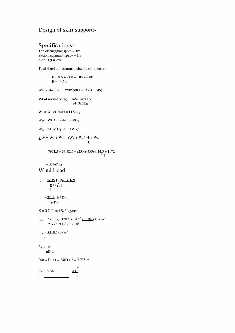
Design of skirt support:-
Specifications:-Top disengaging space = 1m
Bottom separator space = 2mSkirt Hgt = 2m.
Total Height of column including skirt height-
H = 9.5 + 2.00 +1.00 + 2.00
H = 14.5m
Wt. of shell w1 = πdit ρsH = 7931.5kg
Wt of insulation w2 = 1662.24x14.5
= 24102.5kg
Wh = Wt. of Head = 1172 kg.
Wp = Wt. Of plate = 250kg.
WL = wt. of liquid = 335 kg
∑W = W1 + W2 + (WP + WL) H + Wh ts
= 7931.5 + 24102.5 + (250 + 335) x 14.5 + 1172
0.5
= 51767 kg
Wind Load
f wb = (K P1 H DO). (H/2)
π DO2. t
4
=2K P1 H2 DO
π DO2 t.
K = 0.7, P1 = 128.5 kg/m2
f bw = 2 x (0.7) (128.5 x 14.52 x 3.781) kg/cm2
π x (3.781)2 x t x 104
f bw = 0.1592 kg/cm2
t
f ds = w ,
πDmt.
Dm = Di + t = 2400 + 6 = 3.775 m
f ds
=5176
7
=
43.6
5

7/28/2019 Cumene Design 2520of 2520Equipments
http://slidepdf.com/reader/full/cumene-design-2520of-2520equipments 44/72
π x 3.775x t x102 t
51

7/28/2019 Cumene Design 2520of 2520Equipments
http://slidepdf.com/reader/full/cumene-design-2520of-2520equipments 45/72
Seismic load :
f sb = 8 CWH
3 πDo2t
C= 0.08
f sb = 8 x 0.08 x 51767 x 14.5
3π x(3.781)2 x t x104
=0.3565 kg/cm2
tmax possible tensile stress:-
Jf = f db – f sb
807.5 ≥ 43.65 - 0.3565
t t
807.5 ≥ 43.29t
t ≥
0.0536cm.
We can have t = 6mm
max permissible compressive stress:-
Jf ≥ f db + f sb
807.5 ≥ 43.65 + 0.3565
t t
807.5 ≥ 44.00
t
t ≥ 44.00
807.5
t ≥ 0.0545 cm
choose skirt thickness = 6mm
Skirt bearing plate
fc = ∑W + Ms
A Z= 51767 x 4 + Msb
π (4032 - 3772) 2 Msb = 2 CWH.
3
Z = (Dop4 – Dos
4) x π
Dop x 32

7/28/2019 Cumene Design 2520of 2520Equipments
http://slidepdf.com/reader/full/cumene-design-2520of-2520equipments 46/72
= 4034 - 3774 x π
52
32 x
403
fc = 51767 x 4 + 2
0.08 x 51767 x
14.5
π(4032- 3772)
3 3 π (403 4 - 377 4 )32 x 403
=3.2496+0.0266=3.2762
kg/cm2
This is much less than permissible compressive stress
of concrete.
Mmax = fc . b.l2 /2
f = 6 M
max
= 3
fcl2
= 3 x 3.2762 x 152
kg/cm2
b tB2
t
B
2tB
2
f = 9.6 MN/m2 = 9.5 x
102 N/ cm2 = 96
kgf/cm2
tB = √
3x3.2762
x152 96
tB = 4.799cm =48mmbolting hasto be used.
Assume W
min = 45,000 kg.
f c = 45,000 x
4 - 2
x 0.08 x 51767 x
14.5
π (4032 -
3772) 3 π x (4034 – 3774)
32 x 377
= 20.8 – 3.09
= 17.7 kg/cm
j = Mwt =
W min
R
Ms Ms.

7/28/2019 Cumene Design 2520of 2520Equipments
http://slidepdf.com/reader/full/cumene-design-2520of-2520equipments 47/72
Ms =
2 (8.08) x 51767 x 14503
= 4.043 x 10⁶
Mwt = W min x R
= 45,000 x 270
= 12.15 x 10⁶ j =
12.15x10⁶ 4.043x106
= 3.05
j > 1.5 anchor bots are not required.
53

7/28/2019 Cumene Design 2520of 2520Equipments
http://slidepdf.com/reader/full/cumene-design-2520of-2520equipments 48/72
6(C). MINOR EQUIPMENT
CONDENSER (PROCESS DESIGN)
(I) Preliminary Calculations:
(a) Heat Balance:
Vapor flow rate (G) = (R+1)D
= 1.532 x 64525.5 kg/hr
= 98976 kg/hr
= 27.49 kg/s
`
Vapor Feed Inlet Temperature =152.40c.
Let Condensation occur under Isothermal conditions i.e FT=1
Condensate outlet temperature = 152.4 0C
∴Average Temperature = 152.4 0C
Latent heat of vaporisation (λ) :
λ1 = C1 x (1-Tr ) (C2+C3 x Tr +C4 x Tr2
[Perry, 7th edition ; 2nd
chapter]
for cumene, Tc= 631.1K ; Pc = 3.25 x 10
6
Now Tr = T/ Tc = (152.4+273)/ 631 = 0.6735
C1= 5.795 x
107 ; C2 = 0.3956
C3 = 0 ; C4 = 0
λ = 5.795 x 10 7 + (1 - 0.6735)0.3956
= 5.795 x 10⁷ J/Kmole
= 482.153 KJ/ kg
qh = mass flow rate of hot fluid x latent heat of fluid
qh = heat transfer by the hot fluid .
qh = 27.49 x 482.153 = 13254.3 KW
qC= mass flow rate of cold x specific x t
fluid heat
qc = heat transfer by the cold fluid.
Assume : qh = qc.
Inlet temperature of water = 25 0C.

7/28/2019 Cumene Design 2520of 2520Equipments
http://slidepdf.com/reader/full/cumene-design-2520of-2520equipments 49/72
Let the water be untreated water.
54
7/28/2019 Cumene Design 2520of 2520Equipments
http://slidepdf.com/reader/full/cumene-design-2520of-2520equipments 50/72
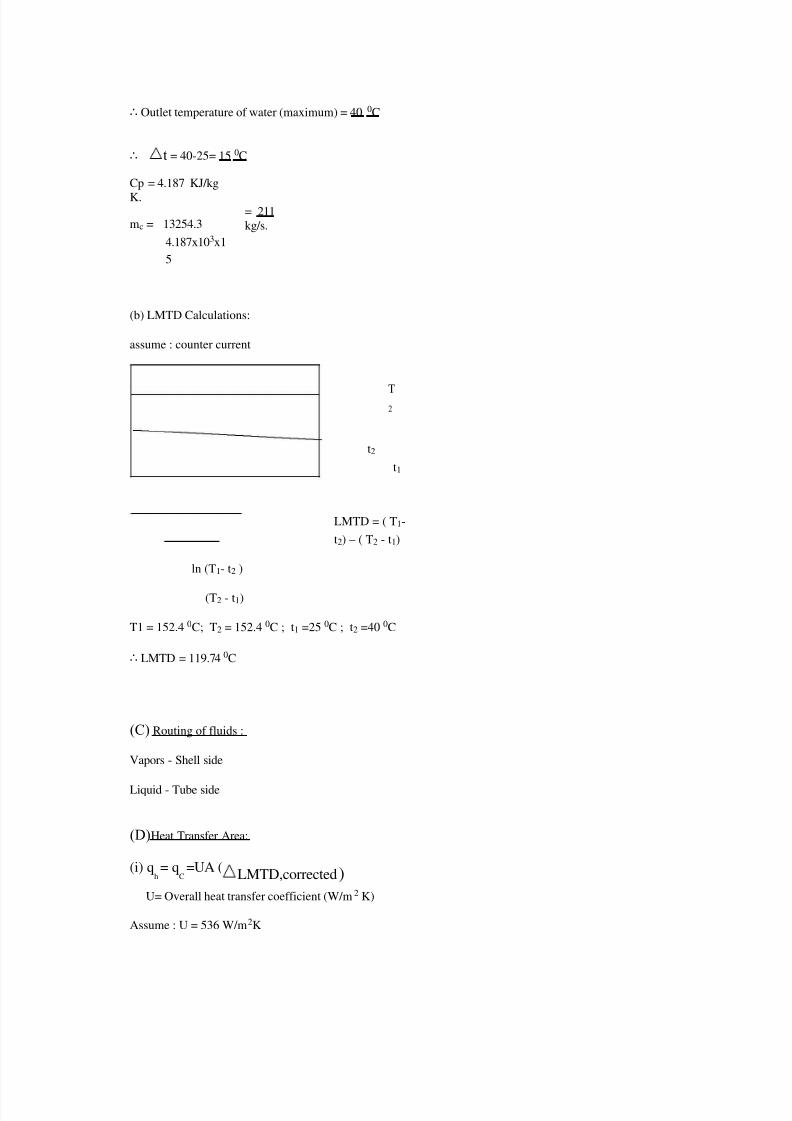
∴ Outlet temperature of water (maximum) = 40 0C
∴ t = 40-25= 15 0C
Cp = 4.187 KJ/kgK.
mc = 13254.3= 211
kg/s.
4.187x103x1
5
(b) LMTD Calculations:
assume : counter current
T1 T
2
t2
t1
LMTD = ( T1-
t2) – ( T2 - t1)
ln (T1- t2 )
(T2 - t1)
T1 = 152.4 0C; T2 = 152.4 0C ; t1 =25 0C ; t2 =40 0C
∴ LMTD = 119.74 0C
(C) Routing of fluids :
Vapors - Shell side
Liquid - Tube side
(D)Heat Transfer Area:
(i) qh= q
C=UA (
LMTD,corrected)
U= Overall heat transfer coefficient (W/m2 K)
Assume : U = 536 W/m2K

7/28/2019 Cumene Design 2520of 2520Equipments
http://slidepdf.com/reader/full/cumene-design-2520of-2520equipments 51/72
∴ A assumed = 13254x103
= 206.5 m2
536 x 119.74
55

7/28/2019 Cumene Design 2520of 2520Equipments
http://slidepdf.com/reader/full/cumene-design-2520of-2520equipments 52/72
(ii) Select pipe size: ( Ref 1: p: 11-10 ; t: 11-2)
Outer diameter of pipe (OD) = 3/4” = 0.01905 m
Inner diameter of pipe (ID) =0.620” = 0.01574 m
Let length of tube =16’ = 4.88m
Let allowance for tubesheet thickness = 0.05m
Heat transfer area of each tube (aheat – transfer) = π x OD x (Length – Allowance)
= π x 0.01905 x (4.88 – 0.05)
= 0.2889
m2
∴ Number of tubes (Ntubes) = A assumed 206.5
=a
heat-
transfer
0.2889
= 715
(iii) Choose Shell diameter: (Ref-1, p: 11-15, t
: 11-3 (F) ) Choose TEMA : P or S. ¾” OD tubes in 1”lar
pitch
1 – 2 Horizontal Condenser
Nearest tube count = 716
∴Ntubes (Corrected
) = 1740
Shell Diameter (Dc) =0.787 m.
∴ Acorrected =206.8 m2
∴ Ucorrected = 536 W/m2K =Uasssumed
(iv) Fluid velocity check :
(a) Vapor side – need not check
(b) Tube side
Flow area (atube) = apipe x Ntubes
Per pass

7/28/2019 Cumene Design 2520of 2520Equipments
http://slidepdf.com/reader/full/cumene-design-2520of-2520equipments 53/72
Ntube passes
a pipe = C.S of pipe = π (ID2)
456
∴ atube = π (0.01574)2
x
716 = 69.71
m2 /pass
4 2
Velocity of fluid (Vpipe) vp =m
pipe
in pipe
ρpipe x
atube
mpipe = mass –flow rate of fluid
in pipe. ρpipe = Density of fluid
in pipe (water)
∴ vp = 211 = 3.04 m/s
995.6 x 69.71
∴ fluid velocity check is
satisfied (II) Film Transfer
Coefficient :
Properties are evaluated at tfilm :
tfilm = tv +1 {tv + (t1+t2) } 152.4 + { 152.4 + (25+40)}] = 1200C2 = 2
2 2
__
a) Shell
side:
Reyonld’s Number (Re) = 4 Γ = 4 W µ µ (Ntubes)
2/3 x L
= 4 27.49
x
=
882
0.000317 (716) € x 4.88
For Horizontal condenser :
Nu = 1.51 { (0D)3 (ρ)2 g}• (Re) -•

7/28/2019 Cumene Design 2520of 2520Equipments
http://slidepdf.com/reader/full/cumene-design-2520of-2520equipments 54/72
µ 2
=1.51 {0.019053(862.3)2 x 9.81 }1/3 (882)-1/3= 321.6
(0.3176 x 10 –3)2
Nu = ho (OD)
K
57

7/28/2019 Cumene Design 2520of 2520Equipments
http://slidepdf.com/reader/full/cumene-design-2520of-2520equipments 55/72
ho = outside heat transfer coefficient (W/m2K)
k = Thermal conductivity of liquid.
ho = Nu x K/(OD) = 839 W/m2K
b) Tube side:
vpipe = 3.04 m/s
Re = v(ID)ρ = 3.04 x 0.01574 x 995.6 = 59,625
µ 0.8 x 10 –3
Pr = µ Cp = 0.8 X 10 –3 x 4.1796 x 10 3= 5.39
K 0.617
hi
(ID)
= 0.023 (Re ) 0.8 (Pr) 0.3K
hi = inside –heat transfer coefficient
hi = 0.023 (59625)0.8
(5.39)0.3 x 0.617
0.01574
hi = 11,751 W/m2K
Fouling factor
(Dirt –coefficient ) = 0.003 [ Ref :1 , p :10-44, t:10-10 ]
1 1 (OD) 1
= + + Fouling factor + x (OD/Davg)
U
0
h
o (ID)h
i Kw
Uo = overall heat –transfer coefficient
1 1
0.019
05 1
= + x
+
0.003/5.678
U
0
839 0.01574 11751
U0 =539 W/m2K
+ {(0.065 x 0.0254)/55} x (0.01905/0.01739)
U0> U
assumed
(III) Pressure Drop Calculations :
a
) Tube Side :

7/28/2019 Cumene Design 2520of 2520Equipments
http://slidepdf.com/reader/full/cumene-design-2520of-2520equipments 56/72
Re =59625
f = 0.079 (Re)-¼ = 0.079 (59625 )-¼
=
0.0021 f = friction factor
58

7/28/2019 Cumene Design 2520of 2520Equipments
http://slidepdf.com/reader/full/cumene-design-2520of-2520equipments 57/72
Pressure Drop along
the pipe length ( P)L = ( H)L x ρ x g
= 4fLVp2 x ρ x g
2g(ID)
= 4 x 0.0021 x 4.88 x 3.04 2 x 995.6 x 9.81
2 x 9.81 x 0.01574
= 11.981
KPa
Pressure Drop in the
end zones (
P
)
e = 2.5 ρ Vp2 = 2.5 x 995.6 x 3.04 2=11.5
KPa2 2
Total pressure drop
in pipe (
to
ta
l
= [11.981 +11.5 ]2
=
46.96 KPa
< 70 KPa
b) Shell side : Kern’s method
Number of baffles =0 ∴Baffle
spacing (B) = 4.88 m
C1 = 2.54 x 10 –2 – 0.01905 = 0.00635
PT = pitch = 25.4 x 10 –2 m
ashell = shell diameter x C1 x B = 0.787 x 0.00635 x 4.88
P
T
25.4x 10–3
= 0.9601
m2
De = 4 { PT x 0.86 PT -
1 π (OD)2} = 4{ (25.4 x 10 –3 )2 x 0.86 - π (0.01905)2}
2 2 4 2 8
(π
do) π ( 0.01905)
2 2
= 22.13mm.
Gs= Superficial velocity in shell =
mshell = 27.49 = 28.63 kg/m2s

7/28/2019 Cumene Design 2520of 2520Equipments
http://slidepdf.com/reader/full/cumene-design-2520of-2520equipments 58/72
ashell 0.9601
(NRe)s =
Gs D c = 28.63 x 22.13 x 10 –3 = 63,363
µ 0.01 x 10⁻³
59
f = 1.87 (63363) –0.2 =
0.1972
∴ Shell side pressure
drop
Gs2
g ]
(
P)s
=4 f
(N
+
1)D x 0.5
2 g De ρ
vapor
Nb = 0
∴Ps
= 4(0.1972) (1) (0.787) (28.63)2 9.81 x
0
.
5
2 x 9.81 (22.13 x 10-3) x
3.48
= 1.049 KPa <14
Kpa
Hence pressure drop on shell side is permissible.
6(D). Mechanical Design
(a) Shell Side:
Material carbon steel (Corrosion allowance = 3mm)
Number of shells =1
Number of passes =2
Working pressure = 1 atm = 0.101 N/mm2
Design pressure = 1.1 x 0.101 = 0.11 N/mm2
Temperature of the inlet = 152.4 0C
Temperature of the outlet = 152.40C
Permissible Strength for
= 95 N/mm2Carbon steel
[IS : 2000-1968
Grade-1,
IS 2825 , Pg : 115 ]

7/28/2019 Cumene Design 2520of 2520Equipments
http://slidepdf.com/reader/full/cumene-design-2520of-2520equipments 59/72
b) Tube side :
Number of tubes =716
Outside diameter =0.01905m
Inside diameter = 0.01574m
Length = 4.88mPitch, lar = 25.4 x 10⁻³ m
Feed =Water.
Working Pressure =1 atm = 0.101 N/ mm2
Design Pressure =0.11 N/mm2
Inlet temperature =25 0C.
Outlet temperature = 40 0C
Shell Side :
60
t = PDi
[ IS 2825, pg:13, eq :
3-1]
2fJ-P
t = Shell thickness
P = design pressure =0.11 N/ mm2 Di = Inner diameter of shell = 787mm f = Allowable stress value = 95 N/mm 2 J=Joint factor = 0.85
ts = 0.11 x 787
=0.536mm
2 x 95 (0.85) –
0.11
Minimum thickness of shell must be 6 mm & corrosion allowance =3 mm ∴ shell thickness, ts =10 mm
Head : (Torrispherical head)
th = PRCW[ Brownell & Young ; pg:
238]2fJ
th = thickness of head
W = ¼{3+ ¥ Rc / Rk }
Rc = Crown radius = outer diameter of shell =787mm
Rk = knuckle radius = 0.06 RC
∴ W =
¼{3 +
√ Rc / 0.06
Rc }=
1.77
∴ th = 0.11 x 787 x 1.77 = 1.05 mm
2x 95x 0.85
Minimum shell thickness should be = 10 mm [IS : 4503-1967]
∴ th = 10mm

7/28/2019 Cumene Design 2520of 2520Equipments
http://slidepdf.com/reader/full/cumene-design-2520of-2520equipments 60/72
Since for the shell, there are no baffles, tie-nods & spacers are not required.
Flanges :
Loose type except lap-joint flange.
Design pressure (p) =0.11 N/mm2
Flange material : IS:2004 –1962 class 2
Bolting steel : 5% Cr Mo steel.
Gasket material = Asbestos composition
Shell side diameter =787mm
Shell side thickness =10mm
Outside diameter of shell =787 + 10x 2 = 807mm
Determination of gasket width :
do = y- pm ½( Brownell & Young ,Pg:227)
di
y-p(m+1)
61

7/28/2019 Cumene Design 2520of 2520Equipments
http://slidepdf.com/reader/full/cumene-design-2520of-2520equipments 61/72
y= Yield stress
m= gasket factor
Gasket material chosen is asbestos with a suitable binder for the operating conditions.
Thickness = 10mm
m= 2.75
y=2.60 x 9.81 = 25.5 N/mm2
do = 25.5 - 0.11 (2.75 )
1 /
2 = 1.004

7/28/2019 Cumene Design 2520of 2520Equipments
http://slidepdf.com/reader/full/cumene-design-2520of-2520equipments 62/72
di
25.5 – 0.11 (2.75+1)
di = inside diameter of gasket = outside diameter of shell= 807 + 5mm
=812 mm
do = outside diameter of the gasket
= 1.004 (812)= 816 mm
Minimum gasket width = 0.816 – 0.812 = 0.002m = 2 mm
2
But minimum gasket width = 6mm ∴
G= 0.812 + 2 (0.006) = 1.256 m
G = diameter at the location of gasket load reaction
Calculation of minimum bolting area :
Minimum bolting area (Am) = Ag= Wg
Sg
Sg = Tensile strength of bolt material (MN/m2)
Consider , 5% Cr-Mo steel, as design material for bolt
At 152.40C.
Sg = 138 x
10 6 N/m2[ B.C.Bhattacharya , pg :
108 ]
Am = 0.3960 x 10
6
= 2.87 x 10⁻³
m2
138 x 10 6
Calculation for optimum bolt size :
g = go = 1.415 go
0.7
07
g = thickness of the hub at the back of the flange
g
=
thickness of the hub at the small end = 10+ 2.5 =12.5mm
62

7/28/2019 Cumene Design 2520of 2520Equipments
http://slidepdf.com/reader/full/cumene-design-2520of-2520equipments 63/72
Selecting bolt size M18x2
R = Radial distance from bolt circle to the connection of hub & back of flange
R= 0.027
C= Bolt circle diameter = ID +2 (1.415 go + R) [B.C.B, pg :122 ]
C= 0.787 +2 (1.415 (0.0125)+0.027)=0.876 m
Estimation of bolt loads :
Load due to design pressure (H) = π G2 P
4H = π (0.824)2 (0.11x10⁶) = 0.0586 x 10⁶N
4
Load to keep the joint tight under operating conditions.
Hp = π g (2b) m p
b= Gasket width = 6mm = 0.006m
Hp = π (0.824 ) ( 2 x 0.006) 2.75 x 0.11 x 106 = 0.00939 x 10⁶ N
Total operating load (Wo) = H+Hp
= ( 0.0586+0.00939 )
= 0.06799 x 10⁶ N
Load to seat gasket under bolt –up condition =Wg.
Wg. = π g b y
= π x 0.824 x 0.006 x 25.5 x 106
Wg = 0.3960 x 10⁶ N
Wg > W0
∴ Wg is the controlling load
∴ Controlling load = 0.3960 x 10⁶ N
Actual flange outside diameter (A) = C+ bolt diameter + 0.02
= 0.876 +0.018+ 0.02= 0.914m
Check for gasket width :
Ab = minimum bolt area = 44 x 1.54 x 10-4 m2
A
b S
g
= (44 x 1.54 x 10-4 )138= 30.10 N/mm2
π GN π x 0.824 x 0.012

7/28/2019 Cumene Design 2520of 2520Equipments
http://slidepdf.com/reader/full/cumene-design-2520of-2520equipments 64/72
2y = 2 x 25.5 = 51 N/mm2
63

7/28/2019 Cumene Design 2520of 2520Equipments
http://slidepdf.com/reader/full/cumene-design-2520of-2520equipments 65/72
AbSg < 2yπ GN
i.e., bolting condition is satisfied.
Flange Moment calculations :
(a) For operating conditions :
WQ = W1 +W2 +W3
W1 = π B2 P = Hydrostatic end force on area inside of flange.
4
W2 = H-W1
W3= gasket load = WQ - H = Hp
B= outside shell diameter = 0.807m
W1 = π (0.807)2 x 0.11 x 106 =
0.05626 x 10⁶ N 4
W2 = H- W1 =(0.0586 – 0.0562) x 106
=0.0026 x 10⁶ N W3 = 0.00939 x 10⁶
N
Wo =( 0.05626 + 0.0026 + 0.00939 ) x
106
= 0.068 x 10⁶ N
Mo = Total flange moment = W1 a1
+ W2 a2 + W3 a3 a1 = C –B ; a2 =
a1 + a3 ; a3 = C -G
2 2 2
C=0.876; B=0.807; G=0.824
a =0.876 –
0.807=0.03
45
2
a= C – G = 0.876 – 0.824 = 0.026
2 2
a
2
= a1 + a3 = 0.0345
+0.026
=
0.0303
2 2
[IS : 2825-1969 ;
pg :53]
[IS 2825-1969,
pg :55]
Mo =[ 0.05626 ( 0.0345) + 0.0026 ( 0.0303) +0.00939 (0.026)

7/28/2019 Cumene Design 2520of 2520Equipments
http://slidepdf.com/reader/full/cumene-design-2520of-2520equipments 66/72
] x 106
=2.264 x 10³ J
(b) For bolting up condition :
Mg = Total bolting Moment =W a3 [IS 2825-
1969, pg :56,
Eqn:4.56]
64

7/28/2019 Cumene Design 2520of 2520Equipments
http://slidepdf.com/reader/full/cumene-design-2520of-2520equipments 67/72
W = (Am +Ab) Sg .
2
Am = 2.87 x 10⁻³
Ab = 44 x 1.5 4x 10-4 = 67.76 x 10⁻⁴ Sg = 138 x 106
W= (2.87 x 10
-3
+ 67.76 x 10
-4
) x 138 x 10
6
= 0.665 x 10
6
2
Mg = 0.665 x 106 x 0.026 = 0.0173 x 10⁶ J
Mg > Mo
∴ Mg is the moment under operating conditions
M= Mg = 0.0173 x 10⁶ J
Calculation of the flange thickness:
t2 = MCFY [B.C.B: , eq:7.6.12]
BSFO
CF= Bolt pitch correction factor = √ Bs / (2d +
t)[IS 2825-1969: 4,
pg:43]
Bs = Bolt spacing = π C = π(0.876) = 0.0625m
n 44
n= number of bolts.
Let CF = 1
SFO = Nominal design stresses for the flange material at design temperature.
SFO = 100 x 106
N
M = 0.0173 x 10⁶
J
B = 1.239
K = A = Flange diameter
= 0.914 =
1.132
B Inner Shell diameter 0.807
Y = 15
(B.C.Bhattacharya, pg : 115,
fig:7.6).t =
√ 0.0173 x 106 x 1 x 15 = 0.0567 m
0.807 x 100 x 106
d = 18 mm
CF
=√ 0.0625 = 0.675
2(18 x 10-3) +
0.0622

7/28/2019 Cumene Design 2520of 2520Equipments
http://slidepdf.com/reader/full/cumene-design-2520of-2520equipments 68/72
CF = (0.675)2
t = 0.0567 x
0.821
= 0.049
m
65

7/28/2019 Cumene Design 2520of 2520Equipments
http://slidepdf.com/reader/full/cumene-design-2520of-2520equipments 69/72
Let t = 50mm = 0.05m
Tube sheet thickness : (Cylindrical Shell) .
T1s = Gc √ KP / f (M.V.Joshi, pg : 249, e.g. : 9.9)
Gc = mean gasket diameter for cover.
P = design pressure.K = factor = 0.25 (when cover is bolted with full faced gasket)
F = permissible stress at design temperature.
t1s = 0.824 √ (0.25 x 0.11 x 106) / ( 95 x 106) = 0.014 m
Channel and channel Cover
th=Gc√ (KP/f) ( K = 0.3 for ring type gasket)= 0.824 √(0.3 x 0.11/ 95)
= 0.015 m =15 mm
Consider corrosion allowance = 4 mm.
th=0.004 + 0.015 = 0.019 m.
Saddle support
Material: Low carbon steel
Total length of shell: 4.88 m
Diameter of shell: 807 mm
Knuckle radius = 0.06 x 0.807 = 0.048 m = ro
Total depth of head (H)= √(Doro /2)
= √
=
Weight of the shell and its contents = 12681.25 kg = W
R=D/2=807/2 mm
Distance of saddle center line from shell end = A =0.5R=0.202 m.
Weight of the vessel and condensate :Density of steel = 7600 kg/m3
Weight of steel vessel = (πdi2 / 4) x ρwater x L x Nt + πds x t x ρsteel x L
+ πdit xLxρsteel x Nt
=π(0.0157)2 /4 x 994 x 4.88 + π x 0.787 x 0.01 x 4.88 x7600
+ π x 0.0157 x 0.0016 x 7600 x 716 x 4.88
W = 3685 kg

7/28/2019 Cumene Design 2520of 2520Equipments
http://slidepdf.com/reader/full/cumene-design-2520of-2520equipments 70/72
66

7/28/2019 Cumene Design 2520of 2520Equipments
http://slidepdf.com/reader/full/cumene-design-2520of-2520equipments 71/72
Longitudinal Bending Moment
M1 = QA[1-(1-A/L+(R2-H2)/(2AL))/(1+4H/(3L))]
Q = W/2(L+4H/3)
= 3685 (4.88 + 4 x 0.139/3)/2
= 9333 kg m
M1=9333x0.202[1-(1.202/4.88+(0.40352-0.1392)/(2x4.88x0.31))/(1+4x0.139/(3x4.88))]
= 11.97 kg-m
Bending moment at center of the span
M2 = QL/4[(1+2(R2-H2)/L)/(1+4H/(3L))-4A/L]
M2 = 9804 kg-m
Stresses in shell at the saddle
(a) At the topmost fibre of the cross section
f 1 =M1 /(k 1π R2 t) k 1=k 2=1
=11.97/(3.14 x 0.40352 x 0.01)
= 0.2340 kg/cm2
Stress in the shell at mid point
f 2 =M2 /(k 2π R2
t)= 191.685 kg/cm2
f 1 and f 2 are well within permissible limits
Axial stress in the shell due to internal pressure
f p= PD/4t
= 0.11 x 106 x 0.807 /4 x 0.01
= 221.9 kg/cm2
f 2 + f p = (191.685 + 221.9) kg/cm2
= 413.585 kg/cm2
The sum f 2 and f p is well within the permissible values.
67

7/28/2019 Cumene Design 2520of 2520Equipments
http://slidepdf.com/reader/full/cumene-design-2520of-2520equipments 72/72
Top Related