


Languages
Pages
Legal


CS485/540 Software EngineeringDesign Concepts (Ch. 8)
Cengiz Günay
Dept. Math & CS, Emory University
Fall 2013Some slides courtesy of Joan Smith, Roger Pressman, and the Internets
Günay (Emory) Design Concepts Fall 2013 1 / 15
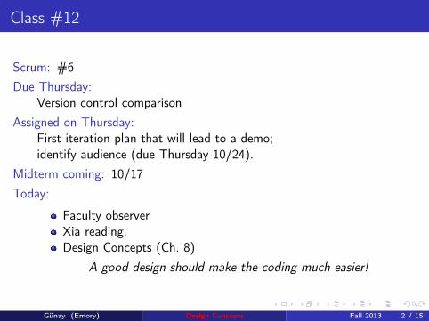
Class #12
Scrum: #6Due Thursday:
Version control comparisonAssigned on Thursday:
First iteration plan that will lead to a demo;identify audience (due Thursday 10/24).
Midterm coming: 10/17Today:
Faculty observerXia reading.Design Concepts (Ch. 8)
A good design should make the coding much easier!
Günay (Emory) Design Concepts Fall 2013 2 / 15

SEPA 7/e: © 2009, Roger Pressman. 9
The Waterfall Model
Communication Planning
ModelingConstruction
Deployment analysis design code
test
project initiation requirement gathering estimating
scheduling tracking
delivery support feedback
These slides are designed to accompany Software Engineering: A Practitionerʼs Approach, 7/e (McGraw-Hill, 2009) Slides copyright 2009 by Roger Pressman. ! 11!
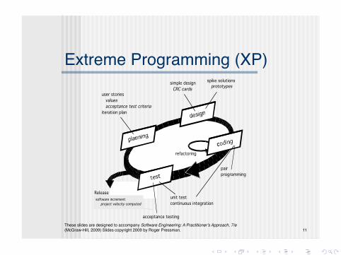
Extreme Programming (XP)!
unit testcontinuous integration
acceptance testing
pairprogramming
Release
user stories values acceptance test criteriaiteration plan
simple design CRC cards
spike solutions prototypes
refactoring
software incrementproject velocity computed

(c) dapperdownapp.com
These slides are designed to accompany Software Engineering: A Practitioner’s Approach, 7/e
(McGraw-Hill, 2009) Slides copyright 2009 by Roger Pressman. 2
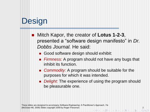
Design
Mitch Kapor, the creator of Lotus 1-2-3,
presented a “software design manifesto” in Dr.
Dobbs Journal. He said:
Good software design should exhibit:
Firmness: A program should not have any bugs that
inhibit its function.
Commodity: A program should be suitable for the
purposes for which it was intended.
Delight: The experience of using the program should
be pleasurable one.

(c) clipartof.com

These slides are designed to accompany Software Engineering: A Practitioner’s Approach, 7/e
(McGraw-Hill, 2009) Slides copyright 2009 by Roger Pressman. 3
Analysis Model -> Design Model
Analysis Model
use-cases - text
use-case diagrams activity diagrams
swim lane diagrams
data flow diagrams
control-flow diagrams processing narratives
f l ow- or i e nt e d
e l e me nt s
be ha v i or a le l e me nt s
c l a ss- ba se d
e l e me nt s
sc e na r i o- ba se d
e l e me nt s
class diagrams analysis packages
CRC models collaboration diagrams
state diagrams
sequence diagramsD a t a / Cla ss D e sign
A rc h it e c t u ra l D e sign
In t e rf a c e D e sig n
Com po ne n t -
Le v e l D e sign
Design Model
These slides are designed to accompany Software Engineering: A Practitioner’s Approach, 7/e
(McGraw-Hill, 2009) Slides copyright 2009 by Roger Pressman. 4
Design and Quality
the design must implement all of the explicit requirements contained in the analysis model, and it must accommodate all of the implicit requirements desired by the customer.
the design must be a readable, understandable guide for those who generate code and for those who test and subsequently support the software.
the design should provide a complete picture of the software, addressing the data, functional, and behavioral domains from an implementation perspective.
These slides are designed to accompany Software Engineering: A Practitioner’s Approach, 7/e
(McGraw-Hill, 2009) Slides copyright 2009 by Roger Pressman. 5
Quality Guidelines A design should exhibit an architecture that (1) has been created using
recognizable architectural styles or patterns, (2) is composed of components that exhibit good design characteristics and (3) can be implemented in an evolutionary fashion
For smaller systems, design can sometimes be developed linearly.
A design should be modular; that is, the software should be logically partitioned into elements or subsystems
A design should contain distinct representations of data, architecture, interfaces, and components.
A design should lead to data structures that are appropriate for the classes to be implemented and are drawn from recognizable data patterns.
A design should lead to components that exhibit independent functional characteristics.
A design should lead to interfaces that reduce the complexity of connections between components and with the external environment.
A design should be derived using a repeatable method that is driven by information obtained during software requirements analysis.
A design should be represented using a notation that effectively communicates its meaning.
These slides are designed to accompany Software Engineering: A Practitioner’s Approach, 7/e
(McGraw-Hill, 2009) Slides copyright 2009 by Roger Pressman. 6
Design Principles
The design process should not suffer from ‘tunnel vision.’
The design should be traceable to the analysis model.
The design should not reinvent the wheel.
The design should “minimize the intellectual distance” [DAV95] between the software and the problem as it exists in the real world.
The design should exhibit uniformity and integration.
The design should be structured to accommodate change.
The design should be structured to degrade gently, even when aberrant data, events, or operating conditions are encountered.
Design is not coding, coding is not design.
The design should be assessed for quality as it is being created, not after the fact.
The design should be reviewed to minimize conceptual (semantic) errors.
From Davis [DAV95]

(c) shopify.com
These slides are designed to accompany Software Engineering: A Practitioner’s Approach, 7/e
(McGraw-Hill, 2009) Slides copyright 2009 by Roger Pressman. 7
Fundamental Concepts Abstraction—data, procedure, control
Architecture—the overall structure of the software
Patterns—”conveys the essence” of a proven design solution
Separation of concerns—any complex problem can be more easily handled if it is subdivided into pieces
Modularity—compartmentalization of data and function
Hiding—controlled interfaces
Functional independence—single-minded function and low coupling
Refinement—elaboration of detail for all abstractions
Aspects—a mechanism for understanding how global requirements affect design
Refactoring—a reorganization technique that simplifies the design
OO design concepts—Appendix II
Design Classes—provide design detail that will enable analysis classes to be implemented

(c) dictionary.com
These slides are designed to accompany Software Engineering: A Practitioner’s Approach, 7/e
(McGraw-Hill, 2009) Slides copyright 2009 by Roger Pressman. 8
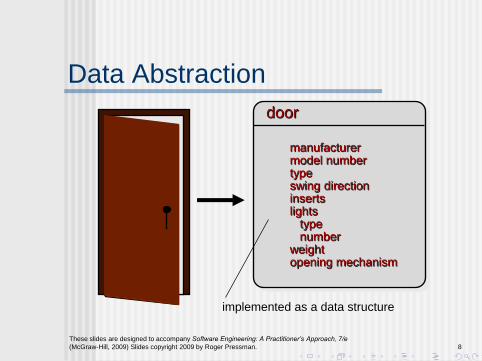
Data Abstraction
door
implemented as a data structure
manufacturer model number type swing direction inserts lights type number weight opening mechanism
These slides are designed to accompany Software Engineering: A Practitioner’s Approach, 7/e
(McGraw-Hill, 2009) Slides copyright 2009 by Roger Pressman. 9
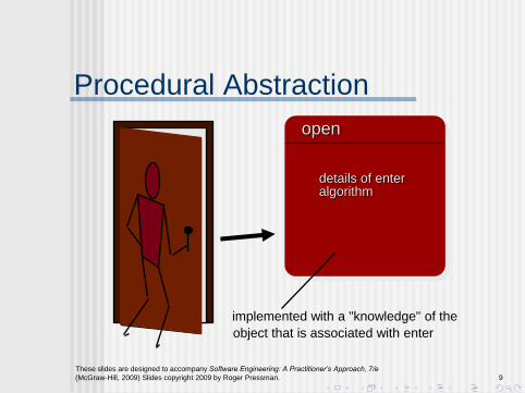
Procedural Abstraction
open
implemented with a "knowledge" of the
object that is associated with enter
details of enter algorithm

(c) dictionary.com

These slides are designed to accompany Software Engineering: A Practitioner’s Approach, 7/e
(McGraw-Hill, 2009) Slides copyright 2009 by Roger Pressman. 10
Architecture “The overall structure of the software and the ways in which that structure provides conceptual integrity for a system.” [SHA95a]
Structural properties. This aspect of the architectural design
representation defines the components of a system (e.g., modules,
objects, filters) and the manner in which those components are
packaged and interact with one another. For example, objects are
packaged to encapsulate both data and the processing that manipulates
the data and interact via the invocation of methods
Extra-functional properties. The architectural design description
should address how the design architecture achieves requirements for
performance, capacity, reliability, security, adaptability, and other system
characteristics.
Families of related systems. The architectural design should draw
upon repeatable patterns that are commonly encountered in the design
of families of similar systems. In essence, the design should have the
ability to reuse architectural building blocks.
(c) dictionary.com
These slides are designed to accompany Software Engineering: A Practitioner’s Approach, 7/e
(McGraw-Hill, 2009) Slides copyright 2009 by Roger Pressman. 11
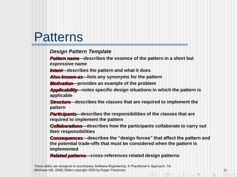
Patterns Design Pattern Template
Pattern name—describes the essence of the pattern in a short but
expressive name
Intent—describes the pattern and what it does
Also-known-as—lists any synonyms for the pattern
Motivation—provides an example of the problem
Applicability—notes specific design situations in which the pattern is
applicable
Structure—describes the classes that are required to implement the
pattern
Participants—describes the responsibilities of the classes that are
required to implement the pattern
Collaborations—describes how the participants collaborate to carry out
their responsibilities
Consequences—describes the “design forces” that affect the pattern and
the potential trade-offs that must be considered when the pattern is
implemented
Related patterns—cross-references related design patterns

An Observer Programming Pattern
(c) 2011 Sommerville, Soft. Eng. 9ed

(c) bp.blogspot.com
These slides are designed to accompany Software Engineering: A Practitioner’s Approach, 7/e
(McGraw-Hill, 2009) Slides copyright 2009 by Roger Pressman. 12
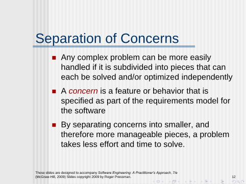
Separation of Concerns
Any complex problem can be more easily
handled if it is subdivided into pieces that can
each be solved and/or optimized independently
A concern is a feature or behavior that is
specified as part of the requirements model for
the software
By separating concerns into smaller, and
therefore more manageable pieces, a problem
takes less effort and time to solve.
These slides are designed to accompany Software Engineering: A Practitioner’s Approach, 7/e
(McGraw-Hill, 2009) Slides copyright 2009 by Roger Pressman. 13
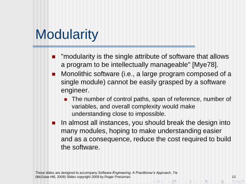
Modularity
"modularity is the single attribute of software that allows
a program to be intellectually manageable" [Mye78].
Monolithic software (i.e., a large program composed of a
single module) cannot be easily grasped by a software
engineer.
The number of control paths, span of reference, number of
variables, and overall complexity would make
understanding close to impossible.
In almost all instances, you should break the design into
many modules, hoping to make understanding easier
and as a consequence, reduce the cost required to build
the software.

These slides are designed to accompany Software Engineering: A Practitioner’s Approach, 7/e
(McGraw-Hill, 2009) Slides copyright 2009 by Roger Pressman. 14
Modularity: Trade-offs What is the "right" number of modules
for a specific software design?
optimal number
of modules
cost of
software
number of modules
module integration
cost
module development cost

(c) bp.blogspot.com

These slides are designed to accompany Software Engineering: A Practitioner’s Approach, 7/e
(McGraw-Hill, 2009) Slides copyright 2009 by Roger Pressman. 15
Information Hiding
module
controlled
interface
"secret"
• algorithm
• data structure
• details of external interface
• resource allocation policy
clients
a specific design decision

These slides are designed to accompany Software Engineering: A Practitioner’s Approach, 7/e
(McGraw-Hill, 2009) Slides copyright 2009 by Roger Pressman. 16
Why Information Hiding?
reduces the likelihood of “side effects”
limits the global impact of local design
decisions
emphasizes communication through
controlled interfaces
discourages the use of global data
leads to encapsulation—an attribute of
high quality design
results in higher quality software
These slides are designed to accompany Software Engineering: A Practitioner’s Approach, 7/e
(McGraw-Hill, 2009) Slides copyright 2009 by Roger Pressman. 17
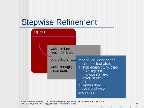
Stepwise Refinement open
walk to door; reach for knob; open door; walk through; close door.
repeat until door opens turn knob clockwise; if knob doesn't turn, then take key out; find correct key; insert in lock; endif pull/push door move out of way; end repeat
These slides are designed to accompany Software Engineering: A Practitioner’s Approach, 7/e
(McGraw-Hill, 2009) Slides copyright 2009 by Roger Pressman. 18
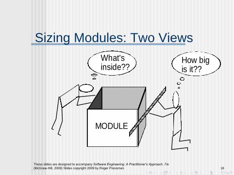
Sizing Modules: Two Views
MODULE
What's inside??
How big is it??
These slides are designed to accompany Software Engineering: A Practitioner’s Approach, 7/e
(McGraw-Hill, 2009) Slides copyright 2009 by Roger Pressman. 19
Functional Independence Functional independence is achieved by developing
modules with "single-minded" function and an "aversion" to excessive interaction with other modules.
Cohesion is an indication of the relative functional strength of a module. A cohesive module performs a single task, requiring little
interaction with other components in other parts of a program. Stated simply, a cohesive module should (ideally) do just one thing.
Coupling is an indication of the relative interdependence among modules. Coupling depends on the interface complexity between
modules, the point at which entry or reference is made to a module, and what data pass across the interface.
These slides are designed to accompany Software Engineering: A Practitioner’s Approach, 7/e
(McGraw-Hill, 2009) Slides copyright 2009 by Roger Pressman. 20
Aspects
Consider two requirements, A and B.
Requirement A crosscuts requirement B “if a
software decomposition [refinement] has been
chosen in which B cannot be satisfied without
taking A into account. [Ros04]
An aspect is a representation of a cross-cutting
concern.
These slides are designed to accompany Software Engineering: A Practitioner’s Approach, 7/e
(McGraw-Hill, 2009) Slides copyright 2009 by Roger Pressman. 21
Aspects—An Example
Consider two requirements for the SafeHomeAssured.com WebApp. Requirement A is described via the use-case Access camera surveillance via the Internet. A design refinement would focus on those modules that would enable a registered user to access video from cameras placed throughout a space. Requirement B is a generic security requirement that states that a registered user must be validated prior to using SafeHomeAssured.com. This requirement is applicable for all functions that are available to registered SafeHome users. As design refinement occurs, A* is a design representation for requirement A and B* is a design representation for requirement B. Therefore, A* and B* are representations of concerns, and B* cross-cuts A*.
An aspect is a representation of a cross-cutting concern. Therefore, the design representation, B*, of the requirement, a registered user must be validated prior to using SafeHomeAssured.com, is an aspect of the SafeHome WebApp.

These slides are designed to accompany Software Engineering: A Practitioner’s Approach, 7/e
(McGraw-Hill, 2009) Slides copyright 2009 by Roger Pressman. 22
Refactoring
Fowler [FOW99] defines refactoring in the following manner: "Refactoring is the process of changing a software system in
such a way that it does not alter the external behavior of the code [design] yet improves its internal structure.”
When software is refactored, the existing design is examined for redundancy unused design elements inefficient or unnecessary algorithms poorly constructed or inappropriate data structures or any other design failure that can be corrected to yield a better
design.

OO!
(c) jacarandafm.com

These slides are designed to accompany Software Engineering: A Practitioner’s Approach, 7/e
(McGraw-Hill, 2009) Slides copyright 2009 by Roger Pressman. 23
OO Design Concepts
Design classes
Entity classes
Boundary classes
Controller classes
Inheritance—all responsibilities of a superclass is
immediately inherited by all subclasses
Messages—stimulate some behavior to occur in the
receiving object
Polymorphism—a characteristic that greatly reduces the
effort required to extend the design

These slides are designed to accompany Software Engineering: A Practitioner’s Approach, 7/e
(McGraw-Hill, 2009) Slides copyright 2009 by Roger Pressman. 24
Design Classes Analysis classes are refined during design to become entity
classes
Boundary classes are developed during design to create the interface (e.g., interactive screen or printed reports) that the user sees and interacts with as the software is used.
Boundary classes are designed with the responsibility of managing the way entity objects are represented to users.
Controller classes are designed to manage
the creation or update of entity objects;
the instantiation of boundary objects as they obtain information from entity objects;
complex communication between sets of objects;
validation of data communicated between objects or between the user and the application.
These slides are designed to accompany Software Engineering: A Practitioner’s Approach, 7/e
(McGraw-Hill, 2009) Slides copyright 2009 by Roger Pressman. 25
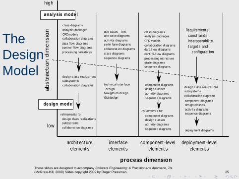
The
Design
Model
process dimension
archit ect ure
element s
int erface
element s
component -level
element s
deployment -level
element s
low
high
class diagrams
analysis packages
CRC models
collaborat ion diagrams
use-cases - t ext
use-case diagrams
act ivit y diagrams
sw im lane diagrams
collaborat ion diagrams dat a f low diagrams
cont rol- f low diagrams
processing narrat ives
dat a f low diagrams
cont rol- f low diagrams
processing narrat ives
st at e diagrams
sequence diagrams
st at e diagrams
sequence diagrams
design class realizat ions
subsyst ems
collaborat ion diagrams
design class realizat ions
subsyst ems
collaborat ion diagrams
ref inement s t o:
deployment diagrams
class diagrams
analysis packages
CRC models
collaborat ion diagrams
component diagrams
design classes
act ivit y diagrams
sequence diagrams
ref inement s t o:
component diagrams
design classes
act ivit y diagrams
sequence diagrams
design class realizat ions
subsyst ems
collaborat ion diagrams
component diagrams
design classes
act ivit y diagrams
sequence diagrams
a na ly sis mode l
de sign mode l
Requirement s:
const raint s
int eroperabilit y
t arget s and
conf igurat ion
t echnical int erf ace
design
Navigat ion design
GUI design

These slides are designed to accompany Software Engineering: A Practitioner’s Approach, 7/e
(McGraw-Hill, 2009) Slides copyright 2009 by Roger Pressman. 26
Design Model Elements Data elements
Data model --> data structures
Data model --> database architecture
Architectural elements
Application domain
Analysis classes, their relationships, collaborations and behaviors are transformed into design realizations
Patterns and “styles” (Chapters 9 and 12)
Interface elements
the user interface (UI)
external interfaces to other systems, devices, networks or other producers or consumers of information
internal interfaces between various design components.
Component elements
Deployment elements
These slides are designed to accompany Software Engineering: A Practitioner’s Approach, 7/e
(McGraw-Hill, 2009) Slides copyright 2009 by Roger Pressman. 27
Architectural Elements
The architectural model [Sha96] is derived from
three sources:
information about the application domain for the
software to be built;
specific requirements model elements such as data
flow diagrams or analysis classes, their relationships
and collaborations for the problem at hand, and
the availability of architectural patterns (Chapter 12)
and styles (Chapter 9).
These slides are designed to accompany Software Engineering: A Practitioner’s Approach, 7/e
(McGraw-Hill, 2009) Slides copyright 2009 by Roger Pressman. 28
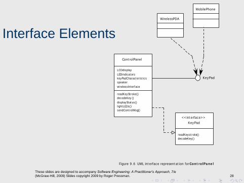
Interface Elements
Cont rolPanel
LCDdisplay
LEDindicat ors
keyPadCharact er ist ics
speaker
wirelessInt erf ace
readKeySt roke()
decodeKey ()
displaySt at us()
light LEDs()
sendCont rolMsg()
Figure 9 .6 UML int erface represent at ion for Co n t ro lPa n e l
KeyPad
readKeyst roke()
decodeKey()
< < int erface> >
WirelessPDA
KeyPad
MobilePhone

These slides are designed to accompany Software Engineering: A Practitioner’s Approach, 7/e
(McGraw-Hill, 2009) Slides copyright 2009 by Roger Pressman. 29
Component Elements
SensorManagementSensor

(c) military.com

These slides are designed to accompany Software Engineering: A Practitioner’s Approach, 7/e
(McGraw-Hill, 2009) Slides copyright 2009 by Roger Pressman. 30
Deployment
Elements
Figure 9 .8 UML deploym ent diagram for SafeHom e
Personal comput er
Security
homeManagement
Surveillance
communication
Cont rol Panel CPI server
Security homeownerAccess
externalAccess

Sustainability(Maintenance)
• StaffingchangesoverQme– Originaldesignermayleave– Originalprogrammermaymoveontootherprojects– Maintenancemaygoonformanyyearsbeyondfirstdeployment
• Design,Architecture,Components– OFenmaintenanceisnotconsidered– Focusis“ideal”designorarchitecture– ConsequencesofcompleximplementaQonreverberateformanyyears
• Example:VoyagesProject– Hibernate,AJAX– SimplechangesrequireprogrammerintervenQon– EvensimplemaplabelmodificaQonsareacomplex,Qme‐consuming
event
CS‐584/Fall2009/EmoryU 3
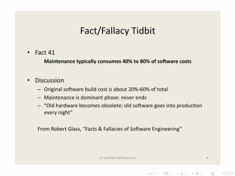
Fact/FallacyTidbit
• Fact41Maintenancetypicallyconsumes40%to80%ofso9warecosts
• Discussion– OriginalsoFwarebuildcostisabout20%‐60%oftotal– Maintenanceisdominantphase:neverends– “Oldhardwarebecomesobsolete;oldsoFwaregoesintoproducQon
everynight”
FromRobertGlass,“Facts&FallaciesofSoFwareEngineering”
CS‐584/Fall2009/EmoryU 4
Top Related